E6607C 配置向导指南
网络分析仪E6607C操作指导 PPT
网络分析仪基础知识
➢ 网络分析仪能精确测量入射能量、反射能量和传输能量
➢ 第一步你必须知道incident ,reflect ,transmitted, 和 insertion loss , return loss之间的关系。
➢从上述图中可以看出,负载在open和short状态下,回路中电磁波都 是全反射的,此时return loss为0db。 这是一个需要matching的前级与后级,前级的输出阻抗和后级的输入 阻抗都必须等于传输线的特性阻抗50Ω,这样才会达到匹配状态。
➢ S12 = reverse transmission coefficient
(isolation)
相关概念
➢ 反射系数 ➢ 回波损耗 ➢ 驻波比 ➢ 传输系数 ➢ 增益/插入损耗 ➢ 群延时 ➢ 史密斯圆图
反射系数Γ
反射系数是反射信号功率与入射信号功率之比。
➢ 当ZL=Z0时, ρ=0; ➢ 当ZL≠ Z0时,0<ρ≤1 ➢ ZL为负载阻抗,Z0为传输线特性阻抗
史密斯圆图
使用网络分析仪测试线损
网络分析仪校准
➢ 将微波连接线接至网分仪,双端口测量使用1、2两端口, 单端口测量二者选一,连接线长度根据需要选择一根或 两根。
➢ 点击菜单栏【sweep】—【sweep type】进行扫频设置, 【start】起始频率,【stop】终止频率,扫频点数 【count】根据需要设置,一般为201或401点。
反射系数分析
传输线三种状态
➢ 1. 匹配工作状态(行波工作状态)、 负载阻抗等于传输线的特性阻抗,即ZL=Z0时,
Γ=0,RL →∞ ,SWR=1。传输线就处于匹配工作状态。
➢ 特征: 沿线只有入射的行波而没有反射波;入射的能量全为
联想 ThinkCentre 超级Q22Gen3用户指南

目录安全事项 . . . . . . . . . . . . . . . . . . . . . . . . . . . . . . . . . . . . . . . . . . . . . . . . . . . . . . . . . . . . . . . . . . . . iii 一般安全原则 . . . . . . . . . . . . . . . . . . . . . . . . . . . . . . . . . . . . . . . . . . . . . . . . . . . . . . . . . . . . . . . . . . . . . . . . . . . . . . . . . . . . . . . . . . . . iii第1章开始使用. . . . . . . . . . . . . . . . . . . . . . . . . . . . . . . . . . . . . . . . . . . . . . . . . . . . . . . . . . . . . . . 1-1物品清单 . . . . . . . . . . . . . . . . . . . . . . . . . . . . . . . . . . . . . . . . . . . . . . . . . . . . . . . . . . . . . . . . . . . . . . . . . . . . . . . . . . . . . . . . . . . . . . . 1-1显示器上接口和控制的位置 . . . . . . . . . . . . . . . . . . . . . . . . . . . . . . . . . . . . . . . . . . . . . . . . . . . . . . . . . . . . . . . . . . . . . . . . . . . . . . . 1-3前视图 . . . . . . . . . . . . . . . . . . . . . . . . . . . . . . . . . . . . . . . . . . . . . . . . . . . . . . . . . . . . . . . . . . . . . . . . . . . . . . . . . . . . . . . . . . . . . . 1-3后视图 . . . . . . . . . . . . . . . . . . . . . . . . . . . . . . . . . . . . . . . . . . . . . . . . . . . . . . . . . . . . . . . . . . . . . . . . . . . . . . . . . . . . . . . . . . . . . . 1-3设置监视器 . . . . . . . . . . . . . . . . . . . . . . . . . . . . . . . . . . . . . . . . . . . . . . . . . . . . . . . . . . . . . . . . . . . . . . . . . . . . . . . . . . . . . . . . . . . . . 1-4安装显示器 . . . . . . . . . . . . . . . . . . . . . . . . . . . . . . . . . . . . . . . . . . . . . . . . . . . . . . . . . . . . . . . . . . . . . . . . . . . . . . . . . . . . . . . . . . 1-4连接线缆 . . . . . . . . . . . . . . . . . . . . . . . . . . . . . . . . . . . . . . . . . . . . . . . . . . . . . . . . . . . . . . . . . . . . . . . . . . . . . . . . . . . . . . . . . . . . 1-8打开显示器和计算机 . . . . . . . . . . . . . . . . . . . . . . . . . . . . . . . . . . . . . . . . . . . . . . . . . . . . . . . . . . . . . . . . . . . . . . . . . . . . . . . . . . . . 1-10第2章调整和使用显示器 . . . . . . . . . . . . . . . . . . . . . . . . . . . . . . . . . . . . . . . . . . . . . . . . . . . . . . . 2-1调整全功能显示器支架 . . . . . . . . . . . . . . . . . . . . . . . . . . . . . . . . . . . . . . . . . . . . . . . . . . . . . . . . . . . . . . . . . . . . . . . . . . . . . . . . . . . 2-1相机旋转 . . . . . . . . . . . . . . . . . . . . . . . . . . . . . . . . . . . . . . . . . . . . . . . . . . . . . . . . . . . . . . . . . . . . . . . . . . . . . . . . . . . . . . . . . . . . . . . 2-3扬声器 . . . . . . . . . . . . . . . . . . . . . . . . . . . . . . . . . . . . . . . . . . . . . . . . . . . . . . . . . . . . . . . . . . . . . . . . . . . . . . . . . . . . . . . . . . . . . . . . . 2-4壁挂(可选) . . . . . . . . . . . . . . . . . . . . . . . . . . . . . . . . . . . . . . . . . . . . . . . . . . . . . . . . . . . . . . . . . . . . . . . . . . . . . . . . . . . . . . . . . . . 2-5安装显示器驱动程序 . . . . . . . . . . . . . . . . . . . . . . . . . . . . . . . . . . . . . . . . . . . . . . . . . . . . . . . . . . . . . . . . . . . . . . . . . . . . . . . . . . . . . 2-5舒适和辅助功能 . . . . . . . . . . . . . . . . . . . . . . . . . . . . . . . . . . . . . . . . . . . . . . . . . . . . . . . . . . . . . . . . . . . . . . . . . . . . . . . . . . . . . . . . . 2-6安排您的工作区域 . . . . . . . . . . . . . . . . . . . . . . . . . . . . . . . . . . . . . . . . . . . . . . . . . . . . . . . . . . . . . . . . . . . . . . . . . . . . . . . . . . . . 2-6放置和观看显示器: . . . . . . . . . . . . . . . . . . . . . . . . . . . . . . . . . . . . . . . . . . . . . . . . . . . . . . . . . . . . . . . . . . . . . . . . . . . . . . . . . . . 2-6关于健康工作习惯的小技巧 . . . . . . . . . . . . . . . . . . . . . . . . . . . . . . . . . . . . . . . . . . . . . . . . . . . . . . . . . . . . . . . . . . . . . . . . . . . . 2-6辅助功能信息 . . . . . . . . . . . . . . . . . . . . . . . . . . . . . . . . . . . . . . . . . . . . . . . . . . . . . . . . . . . . . . . . . . . . . . . . . . . . . . . . . . . . . . . . . . . 2-7调整显示器图像 . . . . . . . . . . . . . . . . . . . . . . . . . . . . . . . . . . . . . . . . . . . . . . . . . . . . . . . . . . . . . . . . . . . . . . . . . . . . . . . . . . . . . . . . . 2-8使用用户控件 . . . . . . . . . . . . . . . . . . . . . . . . . . . . . . . . . . . . . . . . . . . . . . . . . . . . . . . . . . . . . . . . . . . . . . . . . . . . . . . . . . . . . . . . 2-8使用OSD控制 . . . . . . . . . . . . . . . . . . . . . . . . . . . . . . . . . . . . . . . . . . . . . . . . . . . . . . . . . . . . . . . . . . . . . . . . . . . . . . . . . . . . . . . 2-8使用USB接口. . . . . . . . . . . . . . . . . . . . . . . . . . . . . . . . . . . . . . . . . . . . . . . . . . . . . . . . . . . . . . . . . . . . . . . . . . . . . . . . . . . . . . . . 2-9唤醒显示器和系统 . . . . . . . . . . . . . . . . . . . . . . . . . . . . . . . . . . . . . . . . . . . . . . . . . . . . . . . . . . . . . . . . . . . . . . . . . . . . . . . . . . . 2-12选择受支持的显示模式 . . . . . . . . . . . . . . . . . . . . . . . . . . . . . . . . . . . . . . . . . . . . . . . . . . . . . . . . . . . . . . . . . . . . . . . . . . . . . . . . . . 2-13了解电源管理. . . . . . . . . . . . . . . . . . . . . . . . . . . . . . . . . . . . . . . . . . . . . . . . . . . . . . . . . . . . . . . . . . . . . . . . . . . . . . . 2-14保养显示器. . . . . . . . . . . . . . . . . . . . . . . . . . . . . . . . . . . . . . . . . . . . . . . . . . . . . . . . . . . . . . . . . . . . . . . . . . . . . . . . . 2-15第3章参考信息. . . . . . . . . . . . . . . . . . . . . . . . . . . . . . . . . . . . . . . . . . . . . . . . . . . . . . . . . . . . . . . 3-1拆卸显示器 . . . . . . . . . . . . . . . . . . . . . . . . . . . . . . . . . . . . . . . . . . . . . . . . . . . . . . . . . . . . . . . . . . . . . . . . . . . . . . . . . . . . . . . . . . . . . 3-1显示器规格 . . . . . . . . . . . . . . . . . . . . . . . . . . . . . . . . . . . . . . . . . . . . . . . . . . . . . . . . . . . . . . . . . . . . . . . . . . . . . . . . . . . . . . . . . . . . . 3-4故障排除 . . . . . . . . . . . . . . . . . . . . . . . . . . . . . . . . . . . . . . . . . . . . . . . . . . . . . . . . . . . . . . . . . . . . . . . . . . . . . . . . . . . . . . . . . . . . . . . 3-6手动图像设置 . . . . . . . . . . . . . . . . . . . . . . . . . . . . . . . . . . . . . . . . . . . . . . . . . . . . . . . . . . . . . . . . . . . . . . . . . . . . . . . . . . . . . . . . . . . 3-7手动安装显示器驱动程序 . . . . . . . . . . . . . . . . . . . . . . . . . . . . . . . . . . . . . . . . . . . . . . . . . . . . . . . . . . . . . . . . . . . . . . . . . . . . . . 3-8在Windows 7系统中安装显示器驱动程序 . . . . . . . . . . . . . . . . . . . . . . . . . . . . . . . 3-8在Windows 10系统中安装显示器驱动程序. . . . . . . . . . . . . . . . . . . . . . . . . . . . . . . 3-9获得进一步帮助 . . . . . . . . . . . . . . . . . . . . . . . . . . . . . . . . . . . . . . . . . . 3-9附录A. 服务和支持 . . . . . . . . . . . . . . . . . . . . . . . . . . . . . . . . . . . . . . . . . . . . . . . . . . . . . . . . . . . A-1电话技术支持 . . . . . . . . . . . . . . . . . . . . . . . . . . . . . . . . . . . . . . . . . . . . . . . . . . . . . . . . . . . . . . . . . . . . . . . . . . . . . . . . . . . . . . . . . . . A-1附录B. 声明. . . . . . . . . . . . . . . . . . . . . . . . . . . . . . . . . . . . . . . . . . . . . . . . . . . . . . . . . . . . . . . . . B-1商标 . . . . . . . . . . . . . . . . . . . . . . . . . . . . . . . . . . . . . . . . . . . . . . . . . . . . . . . . . . . . . . . . . . . . . . . . . . . . . . . . . . . . . . . . . . . . . . . . . . . B-2电源线和电源适配器 . . . . . . . . . . . . . . . . . . . . . . . . . . . . . . . . . . . . . . . . . . . . . . . . . . . . . . . . . . . . . . . . . . . . . . . . . . . . . . . . . . . . . B-2能效等级 . . . . . . . . . . . . . . . . . . . . . . . . . . . . . . . . . . . . . . . . . . . . . . . . . . . . . . . . . . . . . . . . . . . . . . . . . . . . . . . . . . . . . . . . . . . . . . . B-3《废弃电器电子产品回收处理管理条例》提示性说明 . . . . . . . . . . . . . . . . . . . . . . . . . . . . . . . . . . . . . . . . . . . . . . . . . . . . . . . . . B-3中国环境标志产品认证提示性说明 . . . . . . . . . . . . . . . . . . . . . . . . . . . . . . . . . . . . . . . . . . . . . . . . . . . . . . . . . . . . . . . . . . . . . . . . . B-3有害物质 . . . . . . . . . . . . . . . . . . . . . . . . . . . . . . . . . . . . . . . . . . . . . . . . . . . . . . . . . . . . . . . . . . . . . . . . . . . . . . . . . . . . . . . . . . . . . . . B-4安全事项一般安全原则有关安全使用计算机方面的提示,请访问:/safetyBefore installing this product, read the Safety Information.第1章开始使用本用户指南为用户提供详细的操作说明。
HPc安装指南

CL双模之eNodeB 6.0配置指导书V1.0

(V100R006C00SPC00)eNodeB 6.0版本配置指导书Huawei Technologies Co., Ltd.华为技术有限公司All rights reserved版权所有侵权必究(仅供内部使用)Revision record 修订记录Table of Contents目录1环境描述 (5)1.1组网图 (5)1.1.1实验室整体组网图 (5)1.1.2各个端口连接方式 (5)1.1.3各个网元信息 (6)2激活最小配置 (7)3增加操作维护链路 (8)3.1配置近端维护IP (8)3.2配置远端维护IP (9)4LTE eNodeB配置 (10)4.1配置步骤 (10)4.2具体操作 (10)4.2.1配置eNodeB基本信息 (10)1.增加应用 (10)2.增加基站的标识 (11)3.增加运营商 (11)4.跟踪区域配置 (12)4.2.2配置RRU相关 (13)1.查询RRU 、RRUCHAIN、单板 (14)2.增加机柜 (14)3.增加机框 (14)4.查看单板状态DSP BRD (14)5.增加单板 (15)6.增加RRU链环 (16)7.增加RRU (16)4.2.3配置S1接口 (17)1.增加设备IP (17)2.增加信令链路(即与MME连接的链路) (17)3.增加业务链路(即与SGW连接的链路) (19)4.增加信令链路路由 (20)5.增加业务链路路由 (21)6.增加控制端口承载 (21)7.创建S1接口 (22)8.添加EnodeB Path (23)4.2.4配置站点小区 (23)1.增加扇区 (24)2.增加小区 (24)3.创建小区扇区设备 (26)4.创建小区运营商信息 (26)5.激活小区 (26)5eNodeB配置及升级过程中常见错误 (28)1.RRU无法开工 (28)2.版本升级失败 (28)3.S1链路不通 (28)1环境描述1.1 组网图1.1.1实验室整体组网图SAE 1.1.2各个端口连接方式1.1.3各个网元信息表1网元信息表【注意】1、实验室组网下,为了防止LTE大流量对大网的影响,把eNB的业务IP与维护IP分开。
CC Vector 快速设置向导说明书

To Configure with an Ethernet Cable:Although the CC Vector can be set up from a tablet or a smartphone, it may be easier to use a computer using the included 18” Ethernet cable.Connect the Ethernet cable to your computer’s Ethernet port and to either of the CC Vector’s Ethernet ports on the back of the device. Configure Wirelessly (most popular way):(Internet browser required).1. From your computer, tablet, smartphone or WiFi device, go to the WiFi Settings/Connections and connect to the WiFi Network Name listed on the sticker underneath theCC Vector.2. Enter the WiFi Password when prompted.1WiFi Network Name ORNOTE:Please do not skip any steps. Steps “B1” or “B2” must be done before proceeding.121After plugging in the AC Power cord into the CC Vector Repeater, wait 1 - 2 minutes.Leave this unplugged Attach the small antenna to the CC Vector ™53Connect the 1.5 ft. USB Amplifier cable 4Plug into the CC Vector ™ Connect the CC DX Mile ™to the 30 ft.cable. Make sure to insert cable tip completely inside connector.Connect the AC power plug into a wall outlet 6Attach the large antenna:Please follow the included Antenna Assembly /Mounting guide.See Page 5 for weatherproofing.™Please assemble all items as pictured before proceeding.V15-20222After confirming you have completed Step “B”, open the Internet Browser screen on your device and enter 192.168.18.1 into the Address Bar. Press “Enter” on your keyboard.NOTE: At this point you are connected to the CC Vector but your browser will likely tell you that you are not connected to the internet.This is normal because the CC Vector is not yet setup. Continue with the setup.NOTE: For best performance, your signal should be higher than 50%. For a better signal, try adjusting the orientation and placement of the USB antenna - then click “Rescan” to see if the signal is higher.NOTE: If network in Step “D” does not require a password, then you will not get thisscreen. Proceed to Step “F”.Click onthe WiFinetwork thatyou wantto repeat..3The system will reboot. Please make sure your computer, phone or tablet stays connected to “CCrane” and does not automatically connect to another WiFi network. If no response after 1 minute then close and re-open your web browser screen.If “Status” is “Connected” and “Internet Access” is “Yes”, then you are finished with the setup.Bookmark this page with your web browser in case you need to return to it to check the connection or change networks. You can now close this screen and continue using the internet normally.You should now see a screen similar to this: (Screens may vary on some devices).If “Status” is “Connected” and “Internet Access”is “No”, please wait for 5 to 10 minutes. If no change, please see “Troubleshooting and Tips” #2.Troubleshooting and Tips1. No “Network Names” are showing under the titles for Step “D” under “Pick network to extend” or it continues to show “Scanning”.a. No WiFi networks in range of the USB WiFi Receiver and antenna. Try moving or re-adjust the USB WiFi Receiver (CC DX Mile) and antenna.b. Check to make sure that the small USB end of the cable is properly inserted fully into the USB WiFi receiver’s (CC DX Mile) connector.c. Make sure to use the main USB connector of the USB cable and that it is inserted into the USB Port of the USB Amplifier Cable. After above is checked, click Rescan. Call C. Craneat (800) 522-8863 if you are still not able to see any “Network Names” in Step “D”.4Troubleshooting and Tips - Continued2. The “Status” shows “Connected” and “Internet Access” shows “No”In some cases, if you are at a public WiFi such as an RV Park, Hotel, Hospital, coffee shop, etc. that requires a Username & password, or to accept the User’s Terms and Agreement, open your internet browser and follow their instructions.3. If your CC Vector WiFi Repeater is not working as it should, dropping connections or not being responsive, you should first do a reset of the repeater to see if the problems persist. Other scenarios where you might want to reset your repeater is if you've forgotten the password or mis-configured it and can't get access anymore.To reset your CC Vector WiFi Repeater please follow these steps:- Power up your CC Vector. - Press and hold the reset button on the bottom of the unit for 15 seconds (Use a paper clip or a non-sharp object). - Repeat Steps A1 through G.This process usually works for resetting the CC Vector WiFi Repeater to its factory setting.4. Error Messages “WiFi Connection Failed” - Most likely the password entered for the selected Network to repeat is incorrect. Re-enter correct password.“Connection lost – The Device connection lost” - Your device has lost connection with the CCRANE Network. Most likely your computer, laptop or smartphone re-connected to another nearby network instead of the CCRANE network. Please check your connection to the CCRANE network.Additional Tips• For best performance we recommend 5 to 15 feet of separation between the CC Vector and the USB Antenna.• In some cases you may receive faster WiFi by rotating the USB Antenna horizontally, making sure to aim the broad side towards the distant WiFi network.• It is normal to receive some speed reduction when repeating a WiFi network (because it has to deliver the signal twice).• Some devices such as smartphones, tablets, printers, etc. offerWPS as an alternate form of WiFi connection which does not require a password.To connect devices to the CC Vector without entering a password, press the “WPS ” button when prompted by your device to connect. or WiFi device. •Check the WPS instructions for your computer“WPS” buttonPlease visit our website at for additional information or call 800-522-8863.5WeatherproofingOnce the antenna is securely screwed onto the CC DXMile, use the supplied coaxial seal to completely coverthe connection.We also recommend coating the USB connection withsilicone grease and wrapping with the supplied coaxial seal for added protection.2Before connecting the CC DX Mile to the antenna, coatthe threads of the antenna with the supplied siliconegrease.This will help protect the threads from rust and water incursion.1Cold Weather Protection – Below 32⁰ for the CC DX MileThe CC DX Mile can become intermittent at about 32 degrees F. Hereis a simple suggestion to give it another 10 degrees of protection downto about 22 degrees. The CC DX Mile creates a small amount of heatthat can be retained by using a 10” long piece of pipe insulation madefor 1-1/2” outside diameter pipe. The insulation shown has an “outsidediameter” of about 3”. Three layers of electric tape can be used tocompress and seal the top. It is best to leave the bottom open fordrainage.We suggest removing the insulation when the weather has warmed forthe season or when it approaches 75⁰ F. The unit can be damaged orits lifetime reduced if operated at high temperatures. For temperaturesbelow 22 degrees F you could add another layer of pipe insulationmade for 3 inch pipe. One may be able to find on Amazon by carefullysearching: “Pipe Insulation Tubing 3 inch Water Resistant” andselecting the “.75 inch thickness“ size. These suggestions are forexperimentation at your own risk.21For More Speed connect a WiFi Router - (Not Required)WiFi speed is variable and depends on distance and other conditions. The CC Vector provides enough speed for browsing the Internet with several devices or streaming video on one device.To improve the WiFi speed on all your devices connect a WiFi router (not included) to the #2LAN port of the CC Vector.1) Setup the CC Vector normally using the included directions.2) Confirm that the CC Vector is working by browsing the Internet while wirelessly connected to it.3) Connect the included 18” network cable (or use your own longer network cable) to the #2 LAN port of the CC Vector.4) Connect the other end of the network cable to the “Internet” or “WAN” port on the back of your WiFi router.5) Test the setup by wirelessly connecting your computer or other device to the router’s WiFi signal and browse the Internet.6Back of CC VectorWireless RouterSpecificationsCC DX Mile Long Range General SpecificationsWireless Standard: Frequency Band: Chipset Gain:****************: ****************: ****************: *****************: Certifications: Operating Temperature: Storage Temperature:802.11 B, G, N, AC2.4 & 5 GHz23 dBm11 Mbps54 Mbps150 Mbps433 MbpsFCC, ROHS32° F - 122° F (see weatherproofing on page 5) 14° F - 149° FCC Vector WiFi Repeater General SpecificationsStandards Interface Security Power Frequency Warranty:Wired: IEEE 802.3/802.3uWireless: 802.11b, 802.11g, 802.11nWAN: 10/100BASE-TX Port * 1LAN: 10/100BASE-TX Port * 1USB 2.0 Port * 1WEP EncryptionWPA/WPA2-PSK (Pre-Shared Key)WPA/WPA2 AESWiFi Protected Setup (WPS)Input:100-240V~50/**********Output: 12V, 1A2412~2462MHz (FCC)2412~2472MHz (ETSI)2412~2484MHz (Japan)1-Year Limited7Before UsePlease read these IMPORTANT SAFETY WARNINGS before use. It is important to read and understand all instructions.Lightning You may need to ground your antenna if you live in an area prone to lightning.Power Lines Never mount an antenna near power lines. If a power line falls and comes into contact with your antenna, DO NOT TRY TO REMOVE IT. Call your local power company.Wind Installing an antenna on windy days can be dangerous. Slight winds can create strong forces against the antenna equipment. If you have any doubts about your ability to install the antenna safely, please hire a licensed, bonded professional to do the work. C. Crane is not responsible or liable for damage or injury resulting from antenna installations.1. Read and understand all safety and operating instructions prior to installing the antenna. Retain Instructions: The safety and operating instructions should be retained for future reference.2. Water and Moisture: Coaxial sealant around openings and connections of device and antenna will prevent damage when used outdoors. Use device in a vertical position.3. Never use a utility pole to mount the device and antenna or to use as a support. Never climb a utility pole.4. Antenna installations can be dangerous because many times it involves the use of a ladder and a possible fall. Do Not install antenna on a wet, snowy or windy day or if a thunderstorm is approaching especially when on top of a building or ladder.5. The antenna can be struck by lightning, which can be fatal. We recommend a licensed and insured installation by a qualified person.6. In the event of storms, disconnect the antenna from your device. This will prevent damage caused by lightning.7. The installation or dismantling of any antenna near power lines is dangerous. Each year hundreds of people are killed or injured while attempting to install or dismantle an antenna.Tips to protect your house and contents from lightning: /nlsi_lhm/lEEE_Guide.pdfCopyright ©2022 by C. Crane172 Main Street, Fortuna, CA 95540 • Phone: 1-800-522-8863 • Web: All rights reserved. No part of this booklet may be reproduced, in any form or means whatsoeverwithout permission in writing from C.Crane.。
Studio XPS 7100 设置指南说明书

设置指南设置指南型号: Studio XPS™ 7100管制型号:D03M 系列管制类型: D03M002注、小心和警告注:“注”表示可以帮助您更好地使用计算机的重要信息。
小心:“小心”表示可能会损坏硬件或导致数据丢失,并告诉您如何避免此类问题。
如果您购买的是 Dell™ n 系列计算机,则本文中关于 Microsoft® Windows®操作系统的任何参考内容均不适用。
__________________本说明文件中的信息如有更改,恕不另行通知。
© 2010 Dell Inc. 版权所有,翻印必究。
未经 Dell Inc. 书面许可,严禁以任何形式对这些材料进行复制。
此文本中所使用的商标:Dell、DELL徽标、YOURS IS HERE、Solution Station、Studio XPS 和DellConnect 是 Dell Inc. 的商标;AMD、AMD Athlon和AMD Phenom是 Advanced Micro Devices, Inc. 的商标;Microsoft、Windows和 Windows 开始徽标是 Microsoft Corporation 在美国和/或其他国家或地区的商标或注册商标;Blu-ray Disc是 Blu-ray Disc Association 的商标;Bluetooth是由 Bluetooth SIG, Inc. 所拥有的注册商标,Dell 在其许可下使用。
本说明文件中述及的其他商标和商品名称是指拥有相应标记和名称的公司或其制造的产品。
Dell I nc. 对不属于自己的商标和商品名称不拥有任何所有权。
2010 年 5 月P/N N58TH Rev. A01设置 Studio XPS 台式计算机 . . . . . . . 5提起计算机 . . . . . . . . . . . . . . . . . . . . . .6设定计算机之前 . . . . . . . . . . . . . . . . . . .7连接显示器 . . . . . . . . . . . . . . . . . . . . . .8连接键盘和鼠标. . . . . . . . . . . . . . . . . .10连接网络电缆(可选) . . . . . . . . . . . . .11连接电源电缆. . . . . . . . . . . . . . . . . . . .12按下电源按钮. . . . . . . . . . . . . . . . . . . .12设置操作系统. . . . . . . . . . . . . . . . . . . .13创建系统恢复介质(建议). . . . . . . . . .14连接至 Internet(可选). . . . . . . . . . . .15使用 Studio XPS 台式计算机 . . . . . . 18正面视图功能. . . . . . . . . . . . . . . . . . . .18背面视图功能. . . . . . . . . . . . . . . . . . . .20背面板连接器. . . . . . . . . . . . . . . . . . . .22顶面视图功能. . . . . . . . . . . . . . . . . . . .24软件功能组件. . . . . . . . . . . . . . . . . . . .26 Dell 对接. . . . . . . . . . . . . . . . . . . . . . .27 Dell DataSafe Online Backup. . . . . . . . .28解决问题. . . . . . . . . . . . . . . . . . . . 29哔声代码. . . . . . . . . . . . . . . . . . . . . . .29网络问题. . . . . . . . . . . . . . . . . . . . . . .30电源问题. . . . . . . . . . . . . . . . . . . . . . .31内存问题 . . . . . . . . . . . . . . . . . . . . . . .32锁定和软件问题 . . . . . . . . . . . . . . . . . .33使用支持工具. . . . . . . . . . . . . . . . . 36 Dell 支持中心. . . . . . . . . . . . . . . . . . . .36我的 Dell 下载 . . . . . . . . . . . . . . . . . . .37系统信息. . . . . . . . . . . . . . . . . . . . . . .37硬件故障排除. . . . . . . . . . . . . . . . . . . .39 Dell Diagnostics . . . . . . . . . . . . . . . . . .40目录3目录还原操作系统. . . . . . . . . . . . . . . . . 44系统还原. . . . . . . . . . . . . . . . . . . . . . .45 Dell DataSafe Local Backup . . . . . . . . .46系统恢复介质. . . . . . . . . . . . . . . . . . . .48 Dell Factory Image Restore . . . . . . . . . .49获得帮助. . . . . . . . . . . . . . . . . . . . 51技术支持和客户服务. . . . . . . . . . . . . . .52 DellConnect . . . . . . . . . . . . . . . . . . . . .52在线服务. . . . . . . . . . . . . . . . . . . . . . .52订单状态自动查询服务 . . . . . . . . . . . . .53产品信息. . . . . . . . . . . . . . . . . . . . . . .54根据质保返回商品维修或退款. . . . . . . .54致电之前. . . . . . . . . . . . . . . . . . . . . . .56与 Dell 联络. . . . . . . . . . . . . . . . . . . . .57找到更多信息和资源. . . . . . . . . . . . 58规格. . . . . . . . . . . . . . . . . . . . . . . 60附录. . . . . . . . . . . . . . . . . . . . . . . 66 Macrovision 产品注意事项 . . . . . . . . . .66 NOM 信息,或官方墨西哥标准(仅适用于墨西哥). . . . . . . . . . . . . . .67索引. . . . . . . . . . . . . . . . . . . . . . . 684设置 Studio XPS 台式计算机本节提供了设置 Dell™ Studio XPS™台式计算机的信息。
TForce 550 SE 主板 说明书

TForce 550 SE
第一章: 主板介绍 1.1 前言
感谢您选购我们的产品,在开始安装主板前,请仔细阅读以下安全指导说明: 准备一个清洁稳定的工作环境. 始终从电源出口断开连接. 从抗静电袋取出主板之前,先轻触安全触地器或使用触地手腕 带去除静电,保证自己的安全. 避免触摸主板上的构件.手持电路板的边缘,不要折曲或按压电 路板. 安装之后,确认没有任何小零件置于机箱中,一些小的零件可 能引起电流短路并可能损坏设备. 尽量使电脑远离比如高温、潮湿及有水等危险区.
6.2
Award BIOS 铃声代码......................................................................44
6.3
附加信息 ...........................................................................................44
1.6
主板布局图(Ver 5.x)......................................................................5
1.7
主板布局图(Ver 6.x)......................................................................6
目录
TForce 550 SE
第一章:主板介绍 ..........................................................................1
1.1
前言 .....................................................................................................1
联想V470c笔记本电脑使用说明书 繁体

第一版(2011 年 5 月) © 版權所有 Lenovo 2011。
目錄
第 1 章:了解您的電腦 ...................................1
頂視圖.............................................................. 1 左側視圖.......................................................... 4 右側視圖.......................................................... 6 前視圖.............................................................. 7 底視圖.............................................................. 8
支援網站以查找所有預裝的軟體下載。 根據預設值,您可以在 D 硬碟下的 APP 資料夾中找到用於某些重新安裝的應用程式軟體的 安裝備份。
• 請登入產品 Lenovo Idea 支援網站 尋求服務,例如下載最新的
驅動程式和補丁、保固註冊、技術支援與技術呼叫中心電話清單。
V470c
ba V570c
cd
ab
d
c
a 系統狀態指示燈
如需詳細資訊,請參閱第 21 頁的 “系統狀態指示燈”。
b GPU (圖形處理裝置) 在 Windows 作業系統中滑動此開關,然後放開,以切換本系統使用的 開關 (只有特定機型提 GPU (圖形處理裝置)模式。 供)
c 記憶卡插槽
七彩虹 C.NC19型主板 说明书

简介简介C.NC19 Ver2.0ATX电源接口先将AC交流电(220V)拔除,再将ATX电源接口插入主板的ATX接口,并连接好其他外设连接后,才可将机箱电源的插头插入交流电源插座。
电源插头只能按某一特定方向插入。
S_ATA 1-4接口4个SATA2接口可连接符合串行ATA规格的串行ATA设备。
串行ATA支持所有的ATA和ATAPI设备。
可以通过此接口连接高速Serial AT A硬盘。
前面板插针接口前置面板有电源灯(POWER LED)、扩音器(SPEAKER)、重开机(R S T S W)、硬盘指示灯(H D D L E D)、电源开关(P W R S W)等连接器。
请参考接下来进一步的信息。
步骤2.安装内存主板上有提供2条240-pin 1.8V 插槽,支持2根PC 3200/4300/5400 DDR SDRAM ,最大内存容量可支持至2GB 。
内存速度可以经由B I O S 来控制,您可以在“A d v a n c e dChipset Features Setup ”页找到若干个关于SDRAM 速度的项目。
详细细节请参考BIOS 章节。
安装内存步骤如下:a.将内存条插槽两端的白色固定卡扳开;c.将内存条插入插槽中,插槽两端的白色卡子会因为内存条置入而自动扣到内存条两侧的凹孔中。
b.安装CPU 。
将插座拐角标记对准锁杆顶部最近的插座拐角,确定针角1的方向正确。
不要用力插CPU ,确信CPU 完全插入插槽中。
确认CPU 插座和CPU 的第一脚,将CPU 放入CPU 插座上将锁定杆从未锁定状态拔到锁定状态。
驱动程式安装说明C.NC19 Ver2.0BIOS设定C.NC19 Ver2.0Swap Floppy Drive(交换软驱代号)缺省为Disabled 。
Boot up Floppy Seek (启动时是否检查软驱)BOIS 决定软盘驱动器是40或80轨的。
D i s a b l e d 关闭(缺省设置)。
panasonic CF-19E 系列 便携式计算机 说明书

便携式计算机
型号
CF-19E 系列
目录
准备工作
部件说明 ..................................................................... 3 初次操作 ..................................................................... 6 准备工作 附录 故障排除 实用信息 简介 ............................................................................ 2
3
准备工作
部件说明
左侧
后侧
底部
准备工作
L: 麦克风接口 可使用电容式麦克风。使用其他类型的麦克风时,可能 无法输入声频,也可能导致故障。 用立体声麦克风录制立体声时: 双击通知区域内的 ,单击 [Options] - [Properties], 然后对 [Recording] 添加一个复选标记,单击 [OK] D: 调制解调器端口 [Options] - [Advanced Controls] - [Advanced],去掉 [Mono Microphone] 的复选标记,然后单击 [Close]。 Reference Manual “Modem” 使用带双端子插头的单声道麦克风时: E: LAN 端口 通过上述设定,只能录制左声轨上的声频。 Reference Manual “LAN” 用耳机监听麦克风声频时,不论如何进行上述设定,均 F: SD 内存卡指示灯 无法听到左声轨上的声音。这是计算机规格决定的,并 (闪烁:存取期间) 非故障。 M: 安全锁 Reference Manual “SD Memory Card” 可连接 Kensington 电缆。 G: SD 内存卡插槽 有关详情,请参阅电缆附带的说明书。 Reference Manual “SD Memory Card” N: 外接显示器端口 H: 无线开关 Reference Manual “External Display” Reference Manual “Wireless Switch Utility” O: 串行端口 I: PC 卡插槽 P: 内存模块插槽 Reference Manual “PC Card / ExpressCard” Reference Manual “RAM Module” J: ExpressCard 插槽 Q: 外接天线连接器 R: 扩展总线连接器 Reference Manual “PC Card / ExpressCard” Reference Manual “Port Replicator / Car K: 耳机接口 可以连接耳机或放大扬声器。 连接耳机或放大扬声器时, Mounter” 听不到内置扬声器的声音。 A: DC-IN(直流输入)插孔 B: USB 端口 Reference Manual “USB Devices” C: IEEE 1394 接口连接器 Reference Manual “IEEE 1394 Devices”
网络分析仪E6607C操作指导

2020/3/28
11
2.纯驻波状态
➢ 短路:负载阻抗ZL=0时,Γ=-1, RL=0,SWR →∞ 。 开路:负载阻抗ZL=∞, Γ=1, RL=0 ,SWR →∞
➢3.行驻波状态
“当部Z分L≠反Z射0时”,状Γ态<,1,传此输时线负上载为失“配部,分导行致波传”输状线态上,出现 部分驻波
2020/3/28
➢ 双端口校准需要在每个单端口校准完成后直通两端口末 端,点击直通校准。
➢ 通过【trace】—【format】选择所测格式,可选择S参 数、VSWR驻波比、Smith圆图等,通过【meanings】 设置S参数的具体形式:S11、S22等。
➢ 适当调整【scale】进行所测精度和高度设置,便于精 确分析测量结果。
2020/3/28
7
回波损耗
➢ 反射信号低于入射信号的dB数,是用对数表示反射系数 的幅度特性的一种方法
2020/3/28
8
驻波比
反射除了会使系统中各部件之间传输的最佳功率减少 之外,还会在传输线上产生驻波(两个相反方向的行 波叠加形成)。 在传输线上,信号的最大幅度与最小幅度之比,称为 驻波比。描述负载匹配特性
12
传输系数
传输电压与入射电平之比
2020/3/28
13
插入损耗与增益
➢ 增益:传输电压的绝对值大于入射电压的绝对值 ➢ 插入损耗:传输电压的绝对值小于入射电压的绝对值
➢ 传输系数的相位部分称为插入相位
2020/3/28
14
群延时
➢ 是相位失真的一个有用的度量。是信号通过被测器件的 传输时间随频率变化的量度。群时延可以由对被测器件 的相位响应随时间的变化取微分进行计算
2020/3/28
EXPC-1319系列计算机配件兼容性指南说明书
EXPC-1319 SeriesComponent Compatibility GuideA list of peripheral components suitable for use with the EXPC-1319 series of computers2016/07/05 Version 2.0© 2016 Moxa Inc. All rights reserved.Copyright Notice©2016 Moxa Inc.All rights reserved.TrademarksThe MOXA logo is a registered trademark of Moxa Inc.All other trademarks or registered marks in this manual belong to their respective manufacturers.DisclaimerInformation in this document is subject to change without notice and does not represent a commitment on the part of Moxa.Moxa provides this document as is, without warranty of any kind, either expressed or implied, including, but not limited to, its particular purpose. Moxa reserves the right to make improvements and/or changes to this manual, or to the products and/or the programs described in this manual, at any time.Information provided in this manual is intended to be accurate and reliable. However, Moxa assumes no responsibility for its use, or for any infringements on the rights of third parties that may result from its use.This document might contain unintentional technical or typographical errors. Changes are periodically made to the information herein to correct such errors, and these changes are incorporated into new editions of the publication.Technical Support Contact Information/supportMoxa AmericasToll-free: 1-888-669-2872 Tel: +1-714-528-6777 Fax: +1-714-528-6778 Moxa China (Shanghai office) Toll-free: 800-820-5036Tel: +86-21-5258-9955Fax: +86-21-5258-5505Moxa EuropeTel: +49-89-3 70 03 99-0 Fax: +49-89-3 70 03 99-99 Moxa Asia-Pacific Tel: +886-2-8919-1230 Fax: +886-2-8919-1231Moxa IndiaTel: +91-80-4172-9088 Fax: +91-80-4132-10451. IntroductionThis document lists hardware components that are proven to provide the performance listed in the specification when used with the Moxa EXPC-1319 series of embedded computers, or computers that share basic design features with the EXPC-1319 series. Moxa computers come with multiple peripheral options and are engineered to work with components having different hardware specifications. This flexibility could sometimes lead to compatibility issues. When used with the EXPC-1319 series of embedded computers, peripherals from one manufacturer may not work as well as the ones made by another manufacturer. Moxa provides this list of EXPC-1319 series-compatible components, so that users can be certain of a reliable performance from the EXPC-1319 series, when used with the components listed in this document.2. Testing MethodsTo validate that a component meets the Moxa standards for quality and performance, the following five key compatibility tests are run:•Ambient temperature burn-in•Low temperature hard start•Heat/humidity burn-in•Cyclic high-low temperature burn-in•Vibration testAmbient Temperature Burn-InThe component is mounted on to an EXPC-1319 computer and put through a series of stress tests at an ambient temperature of around 25˚C, for a specified period of time. The duration of the test is determined based on the class of peripherals being tested.Low Temperature Hard StartThe component is mounted on to an unpowered EXPC-1319 computer and then the system is booted up at an extremely low temperature. The designated low temperature value depends on the computer model being tested.Heat/Humidity Burn-InThe component is mounted on to an EXPC-1319 computer, placed in a temperature- and humidity-controlled enclosure, and then put through the burn-in test for a specified period of time. The temperature, humidity, and time targets vary depending on the specification of the computer model used in the test.Cyclic High-Low Temperature Burn-InThe component is mounted on to an EXPC-1319 computer, placed in a temperature controlled enclosure, and then put through the burn-in test wherein the temperature is cyclically varied from very high to very low and back again, over a specified period of time. The target temperature range and the duration of the test can vary depending on the specification of the computer model used in the test.Vibration TestThe component is mounted on to an EXPC-1319 computer that is bound inside an electromagnetic vibrator, and then put through random vibration tests along three orthogonal axes: longitudinal, transverse, and vertical. The vibration tests are compliant with the EN50155/IEC61373 vibration standards.3. Storage EnduranceStorage media, such as SSDs, CF cards, SD cards, Disk on Module, and Cfast, are composed of different electrical components. The main electrical components in these storage media, the NAND-flash memory and NAND-flash controller, impact the storage endurance and lifespan of the storage media.NAND-Flash Memory EnduranceNAND-flash memories have a limit on the number of times they can be programmed and erased (P/E). The P/E cycle as well as the erase count of a NAND-flash memory can be used to determine this limit. For example, an SLC (single-level cell) flash memory has a 60,000 P/E cycle, an MLC (multi-level cell) flash memory has a 3,000 P/E cycle, and TLC NAND flash memories have P/E cycle values up to 1,000. Each flash memory type has a different endurance level, which is why the storage lifespan is based on the flash memory type. Storage that uses SLC type flash memory could have the best endurance level compared with the MLC type storage. SLC storage usually comes with a 5-year OEM warranty (the actual warranty period depends on the original manufacturer). MLC storage only comes with a 1- to 3-year warranty. The major differences between SLC and MLC are: (a) The SLC NAND flash has a lifespan that is around 20 times that of an MLC, and (b) The price can differ by a factor of 4 to 5. The SLC type of storage is recommended for systems that are expected to have high reliability, and for applications that need to frequently write data to a storage medium.Terabytes Written (TBW)TBW is the unit used to evaluate SSD endurance. In actual applications, storage is used for routine operations and data access. Therefore the physical P/E cycle is not appropriate for describing the total rewritable data capacity. The management efficiency of the storage controller also affects thetotal rewritable data capacity result. For these reasons, Joint Electron Device Engineering Council (JEDEC) has defined a standard for SSD endurance evaluation called JESD218, which uses TBW to measure the endurance of the storage memory. By referring to this TBW value, users can easily estimate the storage specification and select a suitable storage for real-life use cases. For example, when routine operations need a maximum of 20 GB and the expected storage lifespan is 3 years, the total rewritable data demand would be 21.9 TBW (20 GB x 365 x 3). In this case, a storage that has more than 21.9 TBW will meet the requirement. We recommend selecting a storage media with a TBW that is greater than the calculated value.4. Declaration for Liability ExclusionThe specifications, warranty terms, and liability of items listed in this guide are the sole responsibility of the original manufacturers. Moxa does not take any responsibility in this regard. Please visit the manufacturers’ official websites for up-to-date product information before purchasing the components.5. Compatible ComponentsPeripheral components that have been tested and found suitable for use with the EXPC-1319 series of computers are listed in this section. The following table lists the Test Codes and their descriptions:Test Code DescriptionA The component has passed the ambient temperature verification testB The component has passed the low temperature verification testC The component has passed the heat/humidity verification testD The component has passed the cyclic high-low temperature verification testE The component has not been tested, but is similar to another component that has been tested in terms of its material and design.F The component has passed the vibration verification testDRAMVendor MemorySize Moxa’s PN Vendor’s PN Interface Chip Brand Speed Test Codes DSL 2 GB 135********A1 D3SP56081XH15BBI DDR3 ProMOS 1333 MHz B, C, DDSL 4 GB 1352110042100 D3SP56082XH12BAI DDR3 ProMOS 1600 MHz B, C, DSSDVendor StorageSize Moxa’sPN Vendor’s PNFlashMemoryBrandFlashMemorySpecController Firmware Warranty WarrantyExclusionTestCodesInnoDisk 32 GB N/A DES25-32GD06SW1QC Toshiba MLC N/A N/A 2 years Endurance >3,000 B, C, DInnoDisk 128 GB N/A DES25-A28D06SW1QC-A31 Toshiba MLC N/A N/A 2 years Endurance >3,000 B, C, DHDDVendor Size Moxa’s PN Vendor’s PN Controller Firmware Test Code HGST 500 GB N/A HTS725050A7E630 / 0J38075 N/A N/A A HGST 1 TB N/A HCC541010A9E680 N/A N/A A HGST 1 TB N/A HTS541010A9E680 N/A N/A A HGST 1 TB N/A HTS721010A9E630 / 0J22423 N/A N/A A HGST 1 TB N/A HTS541010A9E650 N/A N/A A Samsung 2 TB N/A ST2000LM003 N/A N/A A WD 750 GB N/A WD7500BPKT N/A N/A A WD 1 TB N/A WD10JUCT N/A N/A A WD 1 TB N/A WD10JPVT N/A N/A A WD 1 TB N/A WD10SPCX N/A N/A A。
CHI660C电化学工作站操作手册
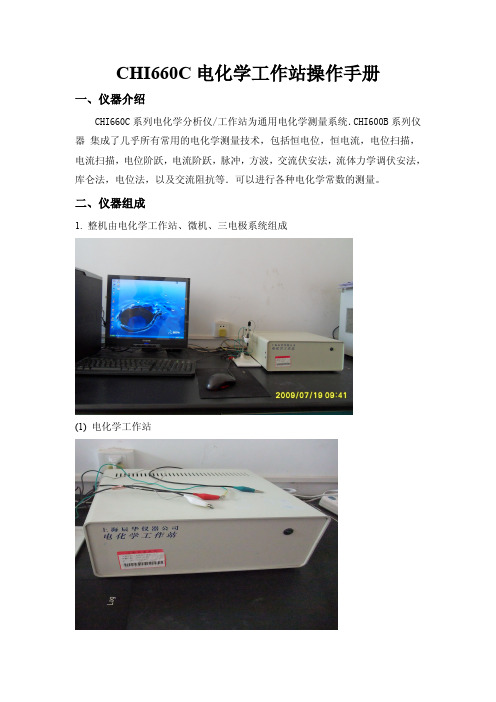
2. 电源线和电极连接好后,将三电极系统插入电解池 3. 打开工作站开关
4. 双击桌面 CHI 快捷方式图标
,打开 CHI 工作站控制界面
双击
4.1 快捷菜单常用符号及意义 :新建; :打开文件; :选择实验技术; :参数设置; :运行; :暂停; :停止; :反向扫描; :放大; :手动设置结果; :
用此命令可终止程序并出口。出口时程序的许多状态可被保存。
4.2.2 Setup设置
Technique 实验技术 CHI电化学分析仪是多功能仪器.用此命令可选择某一电化学实验技术.将
鼠标器指向所选择的技术,然后双击该技术名就行.也可单击技术名,然后按 OK键.如果某伏安法技术有相对应的极谱法(Polarography),亦可选择极谱法. 差别在于极谱法每次采样周期结束后都会送出一个敲击汞滴的TTL信号.如果你 的汞电极可用TTL信号控制的话,你可做极谱实验.如果某伏安法技术有相对应 的溶出法(Stripping),你可在Control(控制)菜单下用StrippingMode(溶出方式) 命令设置溶出法的控制参数并进行溶出伏安法的实验. Parameters 实验参数
设定),SWV可显示正反向或差值电流,IMP可显示波德图或奈奎斯特图,等等. X和Y轴可以拉大缩小。将鼠标移至X或Y轴上,鼠标的显示会变成上下箭头(Y轴) 或左右箭头(X轴),这时按下鼠标的左键,然后移动鼠标,当左键松开时,轴的 范围就改变了。如果双击X或Y轴,会出现一个轴的设定的对话框,可用于改变 轴有关的一些设定。例如轴的标记的表达除了用科学(Scientific)表达(例如一微安 表达为1e-6A)外也可用工程(Engineering)的表达(例如一微安表达为1uA).轴上的 标记线数(Ticks)也可人工设定了。数据图中可允许插入文字。用鼠标在数据区域 中双击,会出现插入文字的对话框。鼠标双击的位置也就是文字显示的第一个字 母的左上角位置。文字的位置,字体,颜色,大小和旋转角度都可调节。如果要 修改或删除现有文字,可将鼠标移至第一个字母的左上角,然后双击,这时会选 中现有文字。这时可作修改或删除。如果将数据存盘的话,输入的文字会和数据 一起被储存。
联想 ThinkPad E570、E570c 和E575安全、保修和设置指南

下载出版物
可从 Lenovo 支持网站获得计算机出版物的电子版本。要下载适用于您所持计算机的出版 物,请访问: https:///support
访问《用户指南》
《用户指南》中包含有关计算机的详细信息。要访问《用户指南》,请执行以下操作: Windows 10: 如果计算机预装了 Lenovo Vantage: 1. 打开“开始”菜单,然后单击 Lenovo Vantage。 2. 展开运行状况和支持,然后单击用户指南。
如果计算机预装了 Lenovo Companion: 1. 打开“开始”菜单,然后单击 Lenovo Companion。 2. 单击支持 → 用户指南。 Windows 7: 1. 从 Windows 桌面上,单击开始,然后单击帮助和支持。随后将打开“Windows 帮助和
服务、支持和保修信息
以下信息描述了您在产品保修期内以及产 品使用期间可以使用的技术支持,同时在 使用过程中,您可以点击以下链接获得在 线技术支持:
/ 如果您需要在中国大陆司法管辖区境内购 买联想增值服务,请访问 ,通过“联 想增值服务”了解详细信息。
下载驱动程序
可从 Lenovo 支持网站获得计算机的最新驱动程序。要下载适用于您所持计算机的最新驱动 程序,请访问: https:///support
使用计算机之前,请阅读此文 档
本文档提供 Lenovo 计算机的关键性安全 和法律法规信息。
安全信息
塑料袋声明
危险 塑料袋具有危险性。请将塑料袋放在婴儿 和儿童接触不到的位置,以避免窒息危 险。
万讯EC660中控设置手册
版权信息本文档中的信息如有变动,恕不另行通知。
此处所涉及的公司名、产品名、人名、人物或数据若非特殊声明,均属虚构,决不代表任何真正的个人、公司、产品或事件。
遵守所有已生效的著作权法是用户的义务。
未经 Wisetek 公司明确的书面许可, 不得为任何目的、以任何手段(电子或机械)复制或传播本文档的任何部分。
本文档可能涉及 WISE 的专利、专有产品、商标、版权或其他知识产权,除非得到 WISE公司的明确书面许可协议, 本文档不授予使用这些专利、专有产品、商标、版权或其他知识产权的任何许可协议。
2003-2007 Beijing Wise Technology & Science Development Co.,ltd. 版权所有。
保留所有权利。
本文档所涉及的其他产品和公司名可能是各自相应所有者的商标。
版权信息 (1)第一部分系统介绍 (4)一、装箱清单 (4)二、外观图 (4)三、尺寸图 (5)四、技术参数 (6)五、系统简述 (7)1、简述 (7)2、独特功能 (7)3、设备连接能力 (8)第二部分系统布线及安装所需工具 (8)一、如何布线与施工 (8)1、系统集成综合布线基础知识 (8)2、多媒体教室如何布线 (9)3、工程实施方法 (9)二、安装调试所需工具 (10)1、工具硬件 (10)2、工具软件 (10)3、编程线缆线序 (10)4、其他工具 (10)第三部分 投影机如何控制 (11)一、投影机控制相关线连接方法 (11)1、投影机电源线连接方法 (11)2、投影机RS232控制线连接方法 (12)1)控制线投影机端连接方法: (12)2)控制线中控端连接方法: (13)3)控制线连接注意事项: (14)3、投影机与计算机串口相连(如何传输中控设置数据) (14)4、投影机红外控制线的连接方法 (15)5、红外学习器连线方法 (17)二、中控机设置软件使用方法(RS232方式控制投影机) (17)1、如何安装设置软件 (17)2、如何使用设置软件 (18)1) 选择中控机型号 (18)2) 选择设置方式 (18)3) 确定投影机控制方式 (19)4) 确定投影机厂商及型号 (20)5) 传输设置数据 (21)三、如何手动添加RS232指令控制投影机 (21)1、为何要手动添加RS232控制指令 (21)2、投影机说明书RS232控制指令事例: (21)3、手动添加控制指令操作步骤: (22)4、组合控制指令(创建新的驱动模版) (24)四、如何用红外控制投影机 (29)1、为什么要用红外来控制投影机呢 (29)2、投影机连线方法 (29)3、红外学习注意事项 (29)4、如何红外学习 (30)5、红外学习高级技巧说明 (32)第四部分 投影屏幕如何控制 (33)一、屏幕连线方法 (33)1、连线规则: (33)2、连接图1: (33)3、连接图2: (34)第五部分 “开门即用,关门即走”功能 (34)一、如何实现“开门即用,关门即走”功能 (34)1、实现此功能的前提 (34)2、什么是“开门即用,关门即走” (34)3、此功能的连线方法 (35)二、如何取消“开门即用,关门即走”功能 (35)1、为何取消此功能 (35)2、连线方法 (35)3、软件设置修改 (36)三、如何实现“一键开机,一键关机”功能 (37)1、什么是“一键开机,一键关机” (37)2、为何要实现“一键开机,一键关机”功能 (37)3、如何实现“一键开机,一键关机”功能 (37)第六部分 其它设备连接方法及软件设置方法 (40)一、台式机 (40)二、笔记本 (41)1、VGA线连接方法 (41)2、音频线连接方法 (41)3、如何邦定卡座音频通道 (42)三、音响设备 (44)1、卡座 (44)2、音箱 (45)第七部分 常见故障排除及技术支持 (45)一、常见故障排除 (45)二、技术支持 (46)1、技术支持网站 (46)2、技术支持邮箱 (46)3、客户服务电话 (46)第一部分系统介绍一、装箱清单序号部件名称型号规格单位数量备注1 控制主机 EC660 台 12 编程电缆 DSUB9pin 根 1emitter 根 13 红外发射线 IR4 音频线 3.5mm立体声根 1根 15 音频线 3.5mm-RCASample 个 1 选配6 红外学习器 IR7 系统光盘张 18 主机电源线 1.5M 根 19 操作手册光盘电子版本 110 屏幕接口电源线根 1二、外观图三、尺寸图钢制操作台固定开孔结构尺寸(单位:mm)四、技术参数指标名称端口类型数量指标复合视频输入RCA 3 0.5V-1Vp-p/75Ω/100MHz(-3db)复合视频输出RCA 2 0.7V-1Vp-p/75Ω/100MHz(-3db) 音频输入 3.5mm立体声 4 -10db/1kΩ/20Hz-20kHz音频输出 3.5mm立体声 2 -10db/1kΩ/20Hz-20kHz模拟RGB输入15pinHD female 3 0.5V-1Vp-p/75Ω/300MHz(-3db)/分离同步模拟RGB输出15pinHD female 2 0.7V-1Vp-p/75Ω/300MHz(-3db)/分离同步单向RS232控制输出工业标准接线端子 1 RS232:波特率(600-115200)、检验方式(无校验、奇校验、偶校验)、数据位(5、6、7、8位)IR控制输出工业标准接线端子 1 IR:中心频率自适应投影机供电标准插座 1 AC220V/5A 屏幕控制端口屏幕专用插座 1 AC220V/5A(内供电)外部设备供电标准插座 1 AC220V/5A AC220V电源输入国标LNG插头 1 AC220V(±15% 50Hz)RS232通讯口DSUB9pin 1 Txd/RxD/GND 数字I/O 工业标准接线端子 1 TTL电平标准总音量控制 1 无级音量调节USB接口 1 前后直通网络接口RJ45 1 以太网(前后直通)存放温湿度-25~50℃/5%~85%(无结露)工作温湿度0~40℃/10%~80%(无结露)五、系统简述1、简述EC660是专为简易多媒体教室设计的一套控制系统。
摩克斯 V2201 系列超级紧凑型 x86 嵌入式计算机安装指南说明书

P/N: 1802022010014 *1802022010014*V2201 SeriesQuick Installation GuideVersion 3.2, April 2022Technical Support Contact Information/support2022 Moxa Inc. All rights reserved.OverviewThe Moxa V2201 Series ultra-compact x86 embedded computer is based on the Intel® Atom™ E3800 Series processor, features the most reliable I/O design to maximize connectivity, and supports dual wireless modules, making it suitable for a diverse range of communication applications. The computer’s thermal design ensures reliable system operation in temperatures ranging from -40 to 85°C, and wireless operation in temperatures ranging from -40 to 70°C with a special purpose Moxa wireless module installed. The V2201 Series supports Proactive Monitoring function for device I/O status monitoring and alerts, system temperature monitoring and alerts, and system power management. Closely monitoring the system status makes it easier to recover from errors and provides the most reliable platform for your applications.Package ChecklistBefore installing the V2201, verify that the package contains the following items:•V2201 embedded computer•Terminal block to power jack converter•Wall mounting kit•Quick installation guide (printed)•Warranty cardNOTE: Please notify your sales representative if any of the above items are missing or damaged.V2201 Panel LayoutThe following figures show the panel layouts of the V2201-W models; for “non-W” models, the five antenna connectors will not be installed during production.Front PanelRight PanelLeft PanelLED IndicatorsThe following table describes the LED indicators located on the front panel of the V2201.LED Name Status Function Power Green Power is on and computer is functioning normally.Off Power is offUser Defined Red Event has occurred Off No alert mSATA Yellow Blinking: Data is being transmittedOff Not connected / No data transmissionSD Card Yellow Blinking: Data is being transmittedOff Not connected / No data transmissionWireless 1 Green Steady On: Link is OnBlinking: Data is being transmittedOff Not connectedWireless 2 Green Steady On: Link is OnBlinking: Data is being transmittedOff Not connectedLED Name Status Function LAN 1Yellow Steady On: 1000 Mbps Ethernet linkBlinking: Data is being transmittedGreen Steady On: 100 Mbps Ethernet linkBlinking: Data is being transmittedOff 10 Mbps Ethernet link or LAN is not connectedLAN 2 Yellow Steady On: 1000 Mbps Ethernet linkBlinking: Data is being transmittedGreen Steady On: 100 Mbps Ethernet linkBlinking: Data is being transmittedOff 10 Mbps Ethernet link or LAN is not connectedTx 1 Green Blinking: Data is being transmittedOff Not connectedTx 2 Green Blinking: Data is being transmittedOff Not connectedRx 1 Yellow Blinking: Data is being transmittedOff Not connectedRx 2 Yellow Blinking: Data is being transmittedOff Not connectedInstalling the Wireless ModulesThe V2201 has two Mini PCIe sockets on the rear panel. One socket only supports USB signals using the MC9090, MC7354, or MC7354 Mini PCIe cards. The other socket supports standard USB and PCIe signals.STEP1: Loosen the four screws located at the middle of the rear panel and open the cover.STEP 2: Insert the wireless module card at an angle.STEP 3: Push the wireless module card down and fasten it with the two screws included with the product.The V2201 has the following two Mini PCIe sockets.Socket 1: USB signal, for 3G/LTE Mini PCIe card (Sierra Wireless MC9090, MC7304, or MC7354). NOTE: The cellular card heat sink is installed in socket 1. Socket 2: Standard USB + PCIe signals, for Wi-Fi Mini PCIe card (SparkLAN WPEA-252NI).STEP 4: Connect the corresponding wireless module cards to connectors of the Mini PCIe sockets.The following five connectors are available:No. 1 & No. 3:For the Wi-Fi Mini PCIe card No. 2 & No. 4:For the 3G/LTE Mini PCIe card No. 5:For the GPS moduleSTEP 5: Replace the rear cover.You can also purchase and install external 3G, 4G, and Wi-Fi antennas from Moxa. Contact a Moxa sales representative for information. After installing the wireless modules and wireless external antennas, the computer should appear as follows:Installing the V2201DIN-rail MountingThe DK-DC50131 die-cast metal kit (shipped only with V2201-E4-W-T-LX; purchase separately for all other models), enables easy and robust installation of the V2201. Use the six M4*6L FMS screws included toattach the DIN-rail mounting kit to the side panel of the V2201.Installation:STEP 1:Insert the upper lip of the DIN rail intothe DIN-rail mounting kit.STEP 2:Press the V2201 towards the DIN railuntil it snaps into place.Removal:STEP 1:Pull down the latch on themounting kit with a screwdriver.STEP 2 & 3:Use the screwdriver to pry theV2201 slightly forward away fromthe DIN rail, and then lift theV2201 upwards to remove it fromthe DIN rail.STEP 4:Press the recessed button on the spring-loaded bracket to lock it into position untilthe next time you need to install theV2201 on to a DIN rail.Wall or Cabinet MountingThe V2201 computers (with the exclusion of the V2201-E4-W-T-LX model) come with two metal brackets for attaching to a wall or the inside of a cabinet. Four screws (Phillips truss-headed M3*6L nickel plated with Nylok®) are included in the kit.Step 1:Use two screws for eachbracket and attach the bracketto the rear of the V2201.Step 2:Use two screws on each side toattach the V2201 to a wall orcabinet.The product package does notinclude the four screws requiredfor attaching the wall-mountingkit to the wall or cabinet; theyneed to be purchasedseparately. We recommendusing standard M3*5L screws.Connector DescriptionPower ConnectorConnect the 9 to 36 VDC LPS or Class 2 power line to the V2201’s terminal block. If the power is supplied properly, the Power LED will light up. The OS is ready when the Ready LED glows a solid green.Grounding the V2201Grounding and wire routing help limit the effects of noise due to electromagnetic interference (EMI). Run the ground connection from the grounding screw (M4) to the grounding surface prior to connecting the power.SG:The Shielded Ground (sometimes calledProtected Ground) contact is the right most oneon the 3-pin power terminal block connector when viewed from the angle shown here.Connect the SG wire to an appropriate grounded metal surface.HDMI OutputsThe V2201 comes with a type A HDMI female connector on the front panel to connect an HDMI monitor.The screw hole above the HDMI connector is used to attach a custom lock to the HDMI connector; a custom lock is needed since the shape of different HDMI connectors are not the same. Please contact a Moxa sales representative for details. Before Attaching the LockAfter Attaching the LockEthernet PortsThe 10/100/1000 Mbps Ethernet ports use RJ45 connectors.Pin 10/100 Mbps 1000 Mbps1 ETx+ TRD(0)+2 ETx- TRD(0)-3 ERx+ TRD(1)+4 – TRD(2)+5 – TRD(2)-6 ERx- TRD(1)-7 – TRD(3)+8 – TRD(3)-Serial PortsThe serial ports use DB9 connectors. Each port can be configured by software for RS-232, RS-422, or RS-485. The pin assignments for the ports are shown in the following table:Pin RS-232 RS-422 RS-485(4-wire) RS-485(2-wire)1 DCD TxDA(-) TxDA(-) –2 RxD TxDB(+) TxDB(+) –3 TxD RxDB(+) RxDB(+) DataB(+)4 DTR RxDA(-) RxDA(-) DataA(-)5 GND GND GND GND6 DSR – – –7 RTS – – –8 CTS – – –SD SlotThe V2201 has an SD slot for storage expansion. The SD slot allows users to plug in an SD 3.0 standard SD card. To install an SD card, gently remove the outer cover from the left, and then insert the SD card into the slot.USIM SlotThe V2201 has a USIM slot for 3G/LTE wireless Internet connections. To install a USIM card, gently remove the outer cover from the left, and then insert the USIM card into the slot.USB HostsThe V2201 has 1 USB 3.0 and 2 USB 2.0 Type-A connectors. 2 USB 2.0 ports are located on the front panel, and 1 USB 3.0 port is on the right panel. The port supports keyboard and mouse and can also be used to connect a Flash drive for storing additional data.Audio InterfaceThe audio output of the V2201 is combined with the HDMI connector.DI/DOThe V2201 comes with four digital inputs and four digital outputs on a 2 x 5 terminal block.Reset ButtonPress the “Reset Button” on the left side panel of the V2201 to reboot the system automatically. Real-time ClockThe V2201’s real-time clock is powered by a lithium battery. Westrongly recommend that you do not replace the lithium battery without help from a qualified Moxa support engineer. If you need to change the battery, contact the Moxa RMA service team.Powering on the V2201To power on the V2201, connect the “terminal block to power jack converter” to the V2201’s DC terminal block (located on the sidepanel), and then connect the 9 to 36 VDC power adapter. The computer is automatically switched on once the power adapter is plugged in. If it does not, press the Power Button to turn on the computer. Note that the Shielded Ground wire should be connected to the top pin of the terminal block. It takes about 30 seconds for the system to boot up. Once the system is ready, the Power LED will light up.Connecting the V2201 to a PCPower on the V2201 computer after connecting a monitor, keyboard, and mouse, and verifying that the power source is ready. Once the operating system boots up, the first step is to configure the Ethernet interface. The factory default settings for the V2201’s LANs are show below (W7E uses DHCP).Default IP AddressNetmaskLAN 1 192.168.3.127 255.255.255.0 LAN 2 192.168.4.127255.255.255.0- 11 - Configuring the Ethernet Interface Linux OSIf you use the console cable to configure network settings for the first time, use the following commands to edit the interfaces file:#ifdown –a //Disable LAN1~LAN2 interface first, before you reconfigure the LAN settings. LAN1 = eth0, LAN2 = eth1// #vi /etc/network/interfaces //check the LAN interface first//After the boot setting of the LAN interface has been modified, use the following commands to immediately activate the LAN settings: #sync; ifup –a W7E OSSTEP 1: Go to Start → Control Panel → Network and Internet → Viewnetwork status and tasks → Change adapter setting.STEP 2: In the Local Area Connection Properties screen, click InternetProtocol (TCP/IP) and then select Properties. Select InternetProtocol Version 4, and then click Properties.STEP 3: Click OK after inputting the proper IP address and netmask.。
MDO4000C 系列 混合域示波器 用户手册说明书
077-1174-02
Copyright © Tektronix.保留所有权利。许可软件产品由 Tektronix、其子公司或提供商所有,受国家版权法及国际条约规定 的保护。Tektronix 产品受美国和外国专利权(包括已取得的和正在申请的专利权)的保护。本文中的信息将取代所有 以前出版的资料中的信息。保留更改技术规格和价格的权利。
控制面板 CP600 2代 CP6407、CP6410、CP6415 操作指南说明书
—OPERATING INSTR UCTIONControl panels CP600 2nd generation CP6407, CP6410, CP6415Contents1Introduction (3)2Safety guide (4)2.1Safety guide (4)2.2Safety notices (4)2.3Markups (5)3Product overview (6)4Standards and approvals (7)4.1Product identification (7)5Technical specifications (9)6Technical data (11)6.1Dimensions (12)6.2Installation environment (13)6.3Safety instruction (14)6.4Installation procedure (14)7Connections (15)7.1CP600 2nd generation (15)7.2Serial port (16)7.3Ethernet port (16)8Power supply, grounding and shielding (17)9Battery (19)9.1Dispose of batteries (19)10Special instruction for use (20)11Cleaning faceplates (20)12Getting started (20)13System settings (21)14Unpacking and packing instructions (23)2 3ADR010470, 3, en_USCONTROL PANELS CP600 2ND GENERAT IONCP600 2nd generation, 3, en_US 31 IntroductionThe operational guidelines described below are information on device technical data, installation, transportation, storage, assembly, use and maintenance. The Manual refers to the following models: PictureType DescriptionCP6407Operator interface with 7” color widescreen display and resistive touchscreenCP6410Operator interface with 10”4 color display and resistive touchscreeCP6415Operator interface with 15” color display and resistive touchscreen2Safety guide2.1Safety guideThe manual contains safety standards that must be respected for the personal safetyand to avoid damage.Indications of attention are divided into three levels of severity.2.2Safety notices4 3ADR010470, 3, en_USCONTROL PANELS CP600 2ND GENERAT ION2.3MarkupsEnumeration.Precondition for an operation instruction or a description.Operation instruction with one step.1. Operation instruction with several steps.Result of an operation.CP600 2nd generation, 3, en_US 53Product overviewCP600 2nd generation HMI products combine state-of-the-art features and great perfor-mance in a compact and robust design.They have been designed to offer competitive price/performance ratio for challenging indus-trial applications where robust devices are a requirement.These products feature a full die-cast aluminum housing. Compatibility with CP600 seriescut-out offers an easy upgrade path for the old series.CP600 2nd generation products have been designed to run PB610 software with outstandingcommunication and graphical options.•Efficient and secure Linux operating system•Gateway function with Server and Client OPC UA•aFull PB610 vector graphic support•Efficient unified programming strategy for web HMI applications6 3ADR010470, 3, en_USCONTROL PANELS CP600 2ND GENERAT ION4Standards and approvalsThe products have been designed for use in an industrial environment in compliance with the2014/30/EU EMC Directive.The products have been designed in compliance with:EN 61000-6-4EN 61000-6-2 EN 61000-4-2EN 61000-4-3EN 61000-4-4EN 61000-4-5EN 61000-4-6EN 61000-4-8EN 61000-4-29EN60945The installation of these devices into the residential, commercial and light-industrial environ-ments is allowed only in the case that special in measures are taken in order to ensure con-formity to EN 61000-6-3.The products are in compliance with the Restrictions on Certain Hazardous Substances(RoHS) Directive 2011/65/EUIn compliance with the above regulations the products are CE marked.4.1Product identificationThe product may be identified through a plate attached to the rear cover. You will have toknow the type of unit you are using for correct usage of the information contained in theguide.An example of this plate is shown in the figure below:Note: the CP6407 label is used as an example for CP600 2nd generation Series.CP600 2nd generation, 3, en_US 783ADR010470, 3, en_USInformation on type plate (example) Description Product model name CP6407Product part number 1SAP540710R0001Serial number S.N.: AAxxxxxxxxxxxxxxxxAA Product version ID V.: xxxxxxxxxxxxxxx Manufacturer addressABB AGEppelheimer Straße 82, 69123 HeidelbergGermanyCONTROL PANELS CP600 2ND GENERAT IONCP600 2nd generation, 3, en_US 95 Technical specificationsTouchscreen technology ResistiveBack-up battery3 V 50 mAh Lithium, rechargeable, not user-replaceable, model VL2330.Fuse AutomaticSerial port RS-232, RS-485, RS-422 software configurable Flash 4 GB RAM512 MBHardware clock Clock/Calendar with back-up battery Accuracy RTC (at 25°C) < 100 ppmEnvironmental conditions Operating temperature -20 … +60 °C (vertical installation) EN 60068-2-14 Storage temperature-20 … +70 °CEN 60068-2-1 EN 60068-2-2 EN 60068-2-14 Operating and storage humidity 5 … 85 % RH not-condensing EN 60068-2-30Vibrations 5 … 9 Hz, 7 mm; 9 … 150 Hz, 1 g p-p EN 60068-2-6 Shock± 50 g, 11 ms, 3 pulses per axis EN 60068-2-27 Protection classFront panel IP66, Rear IP20EN 60529Electromagnetic Compatibility (EMC) Electrostatic discharge immunity test8 kV (air electrostatic discharge)4 kV (contact electrostatic discharge)EN 61000-4-2Radiated, radio-frequency, electromagnetic field immunity test 80 MHz … 1 GHz, 10 V/m 1.4 GHz … 2 GHz, 3 V/m 2 GHz … 2.7 GHz, 1 V/m EN 61000-4-3Burst immunity test±2 kV DC power port±1 kV signal lineEN 61000-4-4Surge immunity test ±0,5 kV DC power port (line to earth) ± 1 KV dc power port (line to line) ±1 kV signal line (line to earth) EN 61000-4-5Immunity to conducted disturbances inducted by radiofrequency field0.15…80 MHz, 10 VEN 61000-4-6Power frequency magnetic field immunity testEnclosure, 50 Hz, 30 A/m EN 61000-4-8Voltage dips, short interruptions and voltage variations immunity test Port: DC mains; Level:0% duration: 10 ms 20 spaces by 1 sTest executed on the 24 VDC of the EUTEN 61000-4-29Durability informationBacklight service life (LED type) 40000 hr. or more(Time of continues operation until the brightness of the backlight reaches 50 % of the rated value when the ambient temperature is 25 °C) - see Note 1Note 1: Extended use in environments where the ambient temperature is 40 °C or higher may degrade backlight quality/reliability/durability.10 3ADR010470, 3, en_US6Technical dataModel CP6407 CP6410 CP6415Display TFT Color / LED TFT Color / LED TFT Color / LEDColors 64K 64K 64KResolution 800X480 800X600 1024X768Diagonal 7” widescreen 10.4” 15”Dimming yes yes yesFlash 4GB 4GB 4GBSD card slot yes yes yesRAM 512MB 512MB 512MBSerial port RS-232,RS-485, RS-422software configurable RS-232,RS-485, RS-422software configurableRS-232,RS-485, RS-422software configurableEthernet port 2 10/100Mb 2 10/100Mb 2 10/100MbUSB port 2 Host interface ver-sion 2.01 max. 100mA, 1 max.500mA 2 Host interface ver-sion 2.01 max. 100mA, 1 max.500mA2 Host interface ver-sion 2.01 max. 100mA, 1 max.500mABattery rechargeable rechargeable rechargeableRTC yes yes yesVoltage 24Vdc (*) 24Vdc (*) 24Vdc (*)Current ratingat 24Vdc0.35A 0.40A0.70AWeight 1.0 Kg 2.0 Kg 3.5 Kg* 10-32VdcFor applications requiring compliance with EN 61131-2 and specifically in reference to 10 ms voltage dips, the power supply range voltage is 18-32Vdc.6.1DimensionsA B C H LCP6407 176 mm6.92”136 mm5.35”40 mm1.57”147,5 mm5.80”187,5 mm7.38”CP6410 276 mm10.86” 221 mm8.70”40 mm1.57”232,5 mm9.15”287,5 mm11.31”CP6415 381 mm15” 296 mm11.65”45 mm1.77”307,5 mm12.10”392,5 mm15.45”6.2Installation environmentAvoid prolonged exposition to direct sunlight to avoid the risk of overheating the device.The equipment is not intended for installation in contact with corrosive chemical compounds. Check the resistance of the front panel to a specific compound before installation.Do not use tools of any kind (screwdrivers, etc.) to operate the touch screen of the panel.In order to meet the front panel protection classifications, proper installation procedure must be followed:•The borders of the cutout must be flat•Screw up each fixing screw until the bezel corner get in contact with the panel.•The cutout for the panel must be of the dimensions indicated in this manual.The IP66 is guaranteed only if:•Max deviation from the plane surface to the cut-out: ≤ 0.5 mm•Thickness of the case where is mounted the equipment: from 1.5 mm to 6 mm•Max surface roughness where the gasket is applied: ≤ 120 μmA.CP64xxB.Installation cut-out6.3 Safety instruction6.4 Installation procedurePlace the fixing brackets contained in the fixing kit as shown in figure.7Connections7.1CP600 2nd generation1.Serial port2.Ethernet Port 03.Ethernet Port 1B Port V2.0, max. 500 mAB Port V2.0, max. 100 mA6.Power Supply7.SD Card Slot7.2 Serial portThe serial port is used to communicate with the PLC or with another type of controller. Different electrical standards are available for the signals in the PLC port connector: RS-232, RS-422, and RS-485.The serial port is software programmable. Make sure you select the appropriate interface in the programming software.Pin RS-232RS-422, RS-4851 GNDGND23 TX CHA-4 RXCHB-56 +5V output +5V output7 CTS CHB+8 RTS CHA+ 9To operate in RS-485 pins 7-8 and 3-4 must be connected externally.The communication cable must be chosen for the type of device being connected.7.3 Ethernet portThe Ethernet port has two status indicators. Please see description in figure.YellowOFF: Valid link has NOT been detected ON: Valid link has been detectedGreenON: No activity BLINKING: Activity8Power supply, grounding and shielding The power supply terminal block is shown in the figure below.Pin Description1 +24 V DC (L+)2 Common (M)3 Ground3 conductors 1,5 mm2 wire size minimum, minimum temperature conductor rating 105 °C.The unit must always be grounded to earth with 1,5 mm2 wire size minimum. Grounding helpslimit the effects of noise due to electromagnetic interference on the control system.Earth connection will have to be done using either the screw or the faston terminal locatednear the power supply terminal block. A label helps identify the ground connection. Also con-nect to ground the terminal 3 on the power supply terminal block.The power supply circuit may be floating or grounded. In the latter case, connect to groundthe power source common as shown in figure (see below) with a dashed line. When using thefloating power scheme, note that the panes internally connects the power common toground with a 1 MΩ resistor in parallel with a 4,7 nF capacitor. The power supply must havedouble or reinforced insulation. The suggested wiring for the power supply is shown below.All the electronic devices in the control system must be properly grounded. Grounding must be performed according to applicable regulations.9 BatteryCP600 2nd generation panels are equipped with rechargeable Lithium battery, not user-re-placeable.The hardware real-time clock (date and time) is maintained by the battery.When the battery is fully charged, it ensures a period of 3 months of data backup at 25 °C.Location of the battery: See “broken circle” in the picture below.9.1Dispose of batteries10Special instruction for use•Install the HMI device according to the accompanying installation instructions.•Ground the HMI device according to the accompanying installation instructions.•Only qualified personnel may install the HMI device or repair it.•Ensure that the aeration holes are not covered.•Care shall be taken not to allow layers of dust to form on the faceplate of the HMI device in a way that might cause the accumulation of static charges.Keep the faceplate of the HMI device clean: the equipment must be cleaned only with asoft cloth and neutral soap product. Do not use solvents.•This device should not be used for purposes and methods other than indicated in this document and in the documentation accompanying the product.11Cleaning faceplates12Getting startedCP600 2nd generation control panels must be programmed with the software PB610.PB610 Panel Builder is a software tool that must be properly installed on a computerrunning Microsoft Windows.There are two options to transfer a PB610 application project to a CP600 2nd generation de-vice:Ethernet Connect the CP600 2nd generation device to the computer with an Ethernetnetwork connection. From PB610 choose the command Run/Download to tar-get. You may have to ensure that the proper firewall policy has been config-ured in the computer to allow PB610 Panel Builder to access the network.USB Create an Update Package using PB610 Panel Builder and copy it to a USBFlash drive.CONTROL PANELS CP600 2ND GENERAT ION CP600 2nd generation, 3, en_US 2113 System settingsCP600 2nd generation control panels have a system settings interface to allow configurationof system options.The user interface of System Settings is based on HTML pages accessible locally on CP600or in remote using a Web browser Chrome v44 or higher on port 443(https://IP /machine_config). Default username is “admin”, default password is “admin”.Use navigation menu on the left side of the screen to browse through the available options.The active item of menu is highlighted on the left side. The right side shows relatedinformation and settings. Based on the size of the CP600 2nd generation screen, both menuand content of selected item may be shown on screen or not.Two modes of operation can be selected in the System Settings:User ModePB610 runtime is running or the CP600 2nd generation device is in “factory default” status. System Mode PB610 runtime is not running or the CP600 2nd generation devicehas a software failure. System Mode includes all options available inUser Mode and offers in additions commands dedicated to systemupgrade and recovery not available when running in User Mode.Activation of System Settings in User Mode:PB610 runtime not runningPress “System Setting” button on the CP600 2nd generation screen. PB610 runtime running Recall context menu and select “System Settings”. To recallthe context menu click and hold any unused area of thetouchscreen for a few seconds.Default hold time is 2 seconds.Activation of System Settings in System Mode:Normal operation If PB610 runtime is not running: Press “System Setting” button onthe CP600 2nd generation screen to enter in System Settings inUser Mode.Select “Restart” → “Config OS” to reboot in System Mode.If PB610 runtime is running: recall context menu and select “SystemSettings”. To recall the context menu click and hold any unused areaof the touchscreen for a few seconds.Default hold time is 2 seconds to enter in System Settings in UserMode.Select “Restart” → “Config OS” to reboot in System Mode. Recovery operation If panel is not responsive, use the so-called “tap-tap” procedure.This procedure consists in tapping the surface of the touchscreenduring the device power-up phase. Tapping frequency must be high.You have to start tapping the touchscreen as soon as power hasbeen applied to the device. When the sequence has beenrecognized, the system shows the message: “TAP-TAP DETECTED”.At this point release touch to boot in User Mode without runningPB610 runtime or press and hold few seconds (selecting so“RESTART: CONFIG OS”) to boot in System Mode.System Settings includes options for basic settings of the device.Language Configure language used for System Settings menu only.System Show information about platform, status and timers (e.g. Systemon time, backlight on time).Logs Enable persistent log for BSP and allows to export it.Date & Time Change the device date and time, including time zone andNTP ServerNetwork Configure IP Address of Ethernet interface and the other networksettings like DNS, Gateway, DHCP, Hostname, routing and bridging. Services Enable/disable services. Example of services are: Open SSH server,Cloud services, SNMP and logging.Management Update of BSP components (Main OS, Config OS, Boot loader,XLoader), check for partitions consistence, update of splash screen,information about usage and size of partitions. The update of MainOS is available only in System Mode, the update of Config OS is onlyin User Mode.Display Adjust brightness, configure automatic backlight turnoff and selectCP600 2nd generation orientation (90°, 180°, 270° and 360°). Restart Restart the device. “Main OS” option restarts as per default in UserMode, “Config OS” option restart panel directly into System Set-tings in System Mode.Authentication Configure password for administrator (“admin”) and for the stand-ard user (“user”). Administrator has full access to System Settings(updates of BSP and other system components).Standard user has some limitations.22 3ADR010470, 3, en_USCONTROL PANELS CP600 2ND GENERAT ION CP600 2nd generation, 3, en_US 2314 Unpacking and packing instructions3A D R 010470, 3, e n _U S © Copyright 2020 - 2021 ABB.All rights reserved.—ABB AGEppelheimer Straße 8269123 HeidelbergGermanyPhone: +49 6221 701 1444Fax: +49 6221 701 1382E-Mail:****************.com /plc/automationbuilder Note:We reserve the right to make technical changes or modify the contents of this document without prior notice. With regard to purchase orders, the agreed particulars shall prevail.ABB AG does not accept any responsibility whatsoever for potential errors or possible lack of information in this document.We reserve all rights in this document and in the subject matter and illustrations contained therein.Any reproduction, disclosure to third parties or utilization of its contents – in whole or in parts – is forbidden without prior written consent of ABB AG.。
- 1、下载文档前请自行甄别文档内容的完整性,平台不提供额外的编辑、内容补充、找答案等附加服务。
- 2、"仅部分预览"的文档,不可在线预览部分如存在完整性等问题,可反馈申请退款(可完整预览的文档不适用该条件!)。
- 3、如文档侵犯您的权益,请联系客服反馈,我们会尽快为您处理(人工客服工作时间:9:00-18:30)。
Agilent E6607C EXT Multiport Wireless Communications T est Set Configuration GuideThe Agilent E6607C EXT multiport wireless communications test set integrates into one box an innova-tive test sequencer, vector signal analyzer (VSA), vector signal generator (VSG), and multiport RF input/output hardware to help you accelerate non-signaling test in cellular and wireless device manufacturing.The integrated multiport adapter is a seamless connectivity solution that enables parallel testing of multiple devices and allows you to achieve significant manufacturing test throughput improvement.Consistent, reliable, and accurate, the U90xxA X-Series measurement applications are specifically optimized for manufacturing test to improve production yield.Standards-based waveform files are provided by N76xxB Signal Studio software to control and test your wireless devices.With U90xxA measurement applicationsand N76xxB Signal Studio software2• Getting Started Guide (E6607-90036) in hardcopy • U9060A-2FP test set measurement application, fixed perpetual license • U9065A-2FP sequence analyzer application, fixed perpetual license • Waveform 5-pack (quantity 2) – E6607C-221 and 222• Country-specific power cord •E6607C-PFR precision frequency referenceapplications and license types (required) U9079A TD-SCDMA measurement applicationU9079A-1FP U9079A-1TPU9079A HSPA measurement applicationU9079A-2FP U9079A-2TPU9080A LTE FDD measurement applicationU9080A-1FP U9080A-1TPU9081A Bluetooth ® measurement applicationU9081A-2FP U9081A-2TPU9082A LTE TDD measurement applicationU9082A-1FP U9082A-1TPN7606B-QFP N7606B-QTP Advanced Bluetooth V 1.1N7606B-RFP N7606B-RTP Advanced Bluetooth V 2.1+EDRN7606B-SFP N7606B-STP Advanced Bluetooth low energy3N7625B-EFP N7625B-ETP Basic LTE TDD R9N7625B-QFP N7625B-QTP Advanced LTE TDD R94Standard 3 year return-to-Agilent warranty R-51B-001-5C 3 year return-to Agilent warranty extended to 5 years E6607C-223-229Waveform license 5-pack 3 to 9E6607C-250-259Waveform license 50-pack 1 to 10Waveform 5 and 50-packs are a cost-effective solution that lets you configure Agilent Signal Studio waveforms for your applications. All instruments are shipped with the E6607C-221 (Waveform 5-pack1) and E6607C-222 (Waveform 5-pack2) as standard.(optional)PS-S20-01Recommended startup assistance PS-S10Remote scheduled productivity assistance. Select 1 to 999 hours. PS-X10Custom services to be qualified by an Agilent technical consultant The following start-up assistance options are available for the E6607C EXT wireless communications test set.E6607CK-250-259Waveform license 50-pack 1 to 10 upgrades E6607CK-KYB Keyboard, USB E6607CK-1CR Rack slide kit E6607CK-1CMRackmount kit E6607CK-1CNFront handle kit E6607CK-1CPRackmount and handle kit E6607CK-HTCHard transit case E6607CK-MSE Mouse, USB The following upgrade kits are available for the E6607C EXT wireless communications test set.R-50C-011-3Agilent upfront calibration support plan: 3 years R-50C-011-5Agilent upfront calibration support plan: 5 years If Option UK6 is required it must be ordered at time of E6607C purchase.(optional)E6607C-KYB Keyboard, USB E6607C-1CR Rack slide kitE6607C-1CMRackmount kit E6607C-1CNFront handle kit E6607C-HTC Hard transit case E6607C-MSE Mouse, USBE6607C 10 MHz to 3.8 GHz Integrated multiport adapter X-Series measurement applications Sequence Studio software Signal Studio softwareChipset software /find/E6607C /find/EXT-C /find/E6607C /find/EXT-C Bluetooth and the Bluetooth logos are trademarks owned by Bluetooth SIG, Inc., U.S.A. and licensed to Agilent Technologies, Inc.cdma2000 is a registered certification mark of the Telecommunications Industry Association.WiMAX, Mobile WiMAX, WiMAX Forum, the WiMAX Forum logo, WiMAX Forum Certified, and the WiMAX Forum Certified logo are US trademarks of the WiMAX Forum.For more information on Agilent Technologies’ products, applications or services, please contact your local Agilent office. The complete list is available at: /find/contactus Americas Canada (877) 894 4414 Brazil (11) 4197 3600Mexico 01800 5064 800 United States (800) 829 4444 Asia Pacific Australia 1 800 629 485China 800 810 0189Hong Kong 800 938 693India 1 800 112 929Japan 0120 (421) 345Korea 080 769 0800Malaysia 1 800 888 848Singapore 1 800 375 8100Taiwan 0800 047 866Other AP Countries (65) 375 8100Europe & Middle East Belgium 32 (0) 2 404 93 40 Denmark 45 45 80 12 15Finland 358 (0) 10 855 2100France 0825 010 700* *0.125 €/minute Germany 49 (0) 7031 464 6333 Ireland 1890 924 204Israel 972-3-9288-504/544Italy 39 02 92 60 8484Netherlands 31 (0) 20 547 2111Spain 34 (91) 631 3300Sweden 0200-88 22 55United Kingdom 44 (0) 118 927 6201For other unlisted countries:/find/contactus (BP-3-1-13)Product specifications and descriptions in this document subject to change without notice. © Agilent Technologies, Inc. 2013 Published in USA, April 29, 2013 5991-2213EN LiteratureEXT wireless communications test set E6607C, Flyer, Literature number (5991-2213EN)EXT wireless communications test set E6607C, Datasheet, Literature number (5991-2215EN)/find/myagilent A personalized view into the information most relevant to you.my /quality Quality Management System Quality Management Sys ISO 9001:2008DEKRA Certified /find/AdvantageServices Accurate measurements throughout the life of your instruments.Agilent Advantage ServicesThree-Year Warranty/find/ThreeYearWarranty Agilent’s combination of product reliability and three-year warranty coverage is another way we help you achieve your business goals: increased confidence in uptime, reduced cost of ownership and greater LAN eXtensions for Instruments puts the power of Ethernet and the Web inside your test systems. Agilent is a founding member of the LXI consortium.myAgilent。