基于FPGA的动态目标跟踪系统设计
《基于FPGA的运动目标检测系统设计》范文
《基于FPGA的运动目标检测系统设计》篇一一、引言随着计算机视觉技术的快速发展,运动目标检测在众多领域中扮演着越来越重要的角色。
为了满足实时性和准确性的需求,基于FPGA(Field Programmable Gate Array)的运动目标检测系统设计成为了研究的热点。
本文将详细介绍基于FPGA的运动目标检测系统的设计思路、实现方法和实验结果。
二、系统设计需求分析运动目标检测系统的设计需求主要包括实时性、准确性和可扩展性。
实时性要求系统能够在短时间内完成图像处理,以便于实时监控和反应;准确性要求系统能够准确地检测出运动目标,减少误检和漏检;可扩展性则要求系统具有良好的硬件架构,以便于后续的升级和维护。
三、系统设计架构基于FPGA的运动目标检测系统设计采用模块化设计思想,主要包括图像采集模块、预处理模块、特征提取模块、目标检测模块和输出模块。
其中,FPGA作为核心处理器,负责各模块之间的协调和数据处理。
1. 图像采集模块:负责从摄像头等设备中获取原始图像数据。
2. 预处理模块:对原始图像数据进行去噪、灰度化等处理,以便于后续的特征提取和目标检测。
3. 特征提取模块:提取图像中的特征,如边缘、纹理、颜色等,以便于目标检测。
4. 目标检测模块:采用适当的算法(如背景减除、光流法等)对图像中的运动目标进行检测。
5. 输出模块:将检测结果以图像或视频的形式输出。
四、关键技术及实现方法1. 图像预处理:采用滤波算法对原始图像进行去噪处理,以提高后续处理的准确性。
同时,将彩色图像转换为灰度图像,以减少数据量和处理复杂度。
2. 特征提取:采用Sobel算子、Canny算子等边缘检测算法提取图像中的特征。
此外,还可以采用深度学习等技术进行特征学习,提高特征提取的准确性和鲁棒性。
3. 运动目标检测:采用背景减除法、光流法等算法对图像中的运动目标进行检测。
其中,背景减除法适用于静态背景下的运动目标检测,而光流法则适用于动态场景下的运动目标检测。
《基于FPGA的运动目标检测系统设计》范文

《基于FPGA的运动目标检测系统设计》篇一一、引言随着科技的发展,运动目标检测在许多领域如安防监控、自动驾驶、人机交互等中发挥着越来越重要的作用。
为了满足实时性和准确性等需求,本文提出了一种基于FPGA(现场可编程门阵列)的运动目标检测系统设计。
该系统通过优化硬件结构和算法设计,实现高效的目标检测,并提供了强大的扩展性和灵活性。
二、系统设计概述本系统设计主要包含以下几个部分:图像采集、预处理、特征提取、目标检测和结果输出。
其中,FPGA作为核心处理单元,负责整个系统的控制和数据处理。
三、图像采集与预处理图像采集部分主要通过摄像头或其他图像传感器获取视频流。
预处理阶段则主要包括去噪、二值化、边缘检测等操作,以增强图像中运动目标的特征,为后续的特征提取和目标检测提供基础。
四、特征提取与目标检测特征提取是运动目标检测的关键步骤,本系统采用基于机器学习和深度学习的算法进行特征提取。
通过训练模型,提取出运动目标的特征信息。
目标检测部分则通过比较特征信息与预设的阈值或模型,判断是否存在运动目标,并给出其位置和大小等信息。
五、FPGA实现与优化FPGA作为本系统的核心处理单元,其性能和效率直接影响到整个系统的性能。
因此,本系统在FPGA上实现了图像处理和目标检测的算法,并进行了优化。
优化措施包括:并行化处理、流水线设计、查找表优化等,以提高数据处理的速度和效率。
此外,FPGA的可编程性使得系统具有很好的扩展性和灵活性,可以根据需求进行定制和升级。
六、系统实现与测试本系统在硬件和软件层面进行了详细的设计和实现。
在硬件方面,选择了合适的FPGA芯片和其他外设,设计了合理的电路和布局。
在软件方面,编写了相应的驱动程序和算法程序,并在实际环境中进行了测试。
测试结果表明,本系统具有较高的实时性和准确性,可以满足实际需求。
七、结论本文设计了一种基于FPGA的运动目标检测系统,通过优化硬件结构和算法设计,实现了高效的目标检测。
基于FPGA+DSP架构的目标跟踪系统设计与实现

基于FPGA+DSP架构的目标跟踪系统设计与实现摘要:本文提出了一种基于FPGA+DSP架构的目标跟踪系统设计与实现方法。
该系统主要通过FPGA实现特征提取和目标检测,通过DSP实现目标跟踪与位置估算。
本文首先介绍了系统设计的基本框架、硬件实现和软件算法,然后详细说明了系统设计过程中遇到的问题及其解决方案,最后对系统的性能进行了评估。
结果表明,该系统可以完成快速、准确的目标跟踪,实现了较高的跟踪精度和实时性。
关键词:FPGA+DSP,目标跟踪,特征提取,目标检测,位置估算,跟踪精度一、引言目标跟踪技术是计算机视觉领域中的重要研究方向之一,其应用范围广泛,例如智能监控、自动驾驶、无人机导航等。
当前,基于计算机的目标跟踪系统大多采用 CPU 或 GPU 为核心架构,但由于计算量大和速度慢等问题,使得其在实际应用中存在诸多限制。
为此,本文提出了一种基于 FPG A+DSP 架构的目标跟踪系统,旨在提高跟踪系统的速度和精度。
二、系统设计该系统主要由图像采集模块、图像处理模块、位置估算模块和跟踪控制模块组成,其中图像采集模块采用 USB 摄像头获取场景图像,图像处理模块主要通过FPGA实现图像特征提取和目标检测,位置估算模块通过 DSP实现目标位置的计算,跟踪控制模块主要实现目标跟踪和控制。
三、硬件实现图像采集模块采用 AVT-BasleracA2040 摄像头,通过USB3.0接口连接到PC机上。
图像处理模块采用Xilinx 的 Kintex-7 FPGA,使用Verilog HDL 实现图像处理算法。
位置估算模块采用TI 的TMS320C6678 DSP,使用C语言实现目标位置的计算。
四、软件算法该系统主要采用了基于HOG+SVM 的目标检测算法和 KCF (Kernelized Correlation Filters) 跟踪算法。
其中 HOG算法可以有效地提取图像中的目标特征,在 SVM分类器的支持下,实现了目标的检测;而 KCF算法可以通过卷积操作实现图像中目标的跟踪。
《基于FPGA的运动目标检测系统设计》范文

《基于FPGA的运动目标检测系统设计》篇一一、引言随着科技的不断进步,计算机视觉在众多领域的应用越来越广泛。
其中,运动目标检测是计算机视觉中的一个重要研究方向。
为了提高运动目标检测的实时性和准确性,本文提出了一种基于FPGA的运动目标检测系统设计。
该系统设计能够快速准确地检测出运动目标,并具有较高的实时性,为相关领域的应用提供了有力的技术支持。
二、系统设计概述本系统设计基于FPGA(现场可编程门阵列)实现运动目标检测。
FPGA具有并行计算、可定制和可扩展等优点,非常适合于实现复杂的图像处理算法。
系统设计主要包括图像采集、预处理、特征提取、目标检测和输出等模块。
三、图像采集与预处理图像采集模块负责获取视频流或图像序列。
预处理模块对采集到的图像进行去噪、灰度化、二值化等操作,以便后续的特征提取和目标检测。
去噪操作可以消除图像中的无关信息,提高图像的信噪比;灰度化和二值化操作可以将彩色图像转换为灰度图像或二值图像,简化后续处理。
四、特征提取与目标检测特征提取模块从预处理后的图像中提取出运动目标的特征。
这些特征包括形状、大小、纹理等,可以有效地描述运动目标的特性。
目标检测模块根据提取的特征,采用合适的算法(如背景减除法、光流法、帧间差分法等)检测出运动目标。
在FPGA上实现特征提取和目标检测时,需要采用并行化和流水线等技术,以提高处理速度。
此外,针对不同的应用场景和需求,可以定制不同的特征提取和目标检测算法,以提高系统的灵活性和适应性。
五、系统实现与优化系统实现过程中,需要选用合适的FPGA芯片和开发工具,如Xilinx或Altera的FPGA芯片和HDL语言(如Verilog或VHDL)进行开发。
在实现过程中,需要考虑到系统的实时性、功耗、面积等因素,进行优化设计。
为了进一步提高系统的性能,可以采取以下优化措施:1. 优化算法:针对特定的应用场景和需求,可以优化特征提取和目标检测算法,提高其处理速度和准确性。
《基于FPGA与机器视觉的运动跟踪系统设计》范文

《基于FPGA与机器视觉的运动跟踪系统设计》篇一一、引言随着科技的不断进步,运动跟踪系统在众多领域中发挥着越来越重要的作用,如安防监控、无人驾驶、智能机器人等。
为了提高运动跟踪的实时性和准确性,本文提出了一种基于FPGA (现场可编程门阵列)与机器视觉的运动跟踪系统设计。
该系统结合了FPGA的高性能计算能力和机器视觉的图像处理技术,能够实现对运动目标的快速、准确跟踪。
二、系统设计概述本运动跟踪系统设计主要包括硬件和软件两部分。
硬件部分以FPGA为核心,配合摄像头、存储器等设备;软件部分则包括图像处理算法、跟踪算法等。
通过软硬件的结合,实现运动目标的实时跟踪。
三、硬件设计1. FPGA选择:FPGA具有高性能、可编程、低功耗等优点,是本系统的核心部件。
选择合适的FPGA芯片,根据系统需求进行配置和优化。
2. 摄像头:选用高分辨率、低噪声的摄像头,以保证图像质量。
摄像头与FPGA通过接口进行连接,实现图像数据的实时传输。
3. 存储器:选用高速、大容量的存储器,用于存储图像数据和处理结果。
四、软件设计1. 图像处理算法:本系统采用机器视觉技术,通过图像处理算法实现对运动目标的检测和跟踪。
包括背景提取、目标检测、特征提取等步骤。
2. 跟踪算法:本系统采用基于FPGA的并行处理技术,实现多目标跟踪。
通过卡尔曼滤波、均值漂移等算法,实现对运动目标的准确跟踪。
3. 系统软件架构:系统软件架构采用模块化设计,包括图像采集模块、图像处理模块、跟踪算法模块等。
各模块之间通过接口进行数据传输和交互。
五、系统实现1. 图像采集:通过摄像头实时采集图像数据,传输至FPGA。
2. 图像处理:FPGA对图像数据进行处理,包括背景提取、目标检测、特征提取等步骤。
3. 跟踪算法实现:FPGA并行处理技术实现多目标跟踪,通过卡尔曼滤波、均值漂移等算法,实现对运动目标的准确跟踪。
4. 数据存储与传输:处理结果存储至存储器,并通过接口传输至其他设备或系统。
《基于FPGA的运动目标检测系统设计》范文

《基于FPGA的运动目标检测系统设计》篇一一、引言随着计算机视觉技术的快速发展,运动目标检测在许多领域中扮演着越来越重要的角色。
从智能交通监控到安全防护系统,运动目标检测技术都发挥着关键作用。
传统的运动目标检测方法通常依赖于中央处理器(CPU)进行计算,但面对复杂的实时视频流处理任务,其处理速度和效率显得捉襟见肘。
因此,本文提出了一种基于FPGA的运动目标检测系统设计,以实现更快速、更准确的运动目标检测。
二、系统设计概述本系统设计采用FPGA作为核心处理器,通过硬件加速的方式实现运动目标检测。
系统主要由图像采集模块、预处理模块、运动检测模块和输出模块四个部分组成。
其中,图像采集模块负责捕获视频流;预处理模块对图像进行去噪、增强等处理;运动检测模块是本系统的核心,通过算法实现运动目标的检测;输出模块将检测结果以可视化形式呈现。
三、硬件平台设计FPGA作为一种可编程的逻辑器件,具有并行处理、高速运算等优势,是运动目标检测系统的理想选择。
在硬件平台设计方面,我们选择了适合视频处理的FPGA芯片,并设计了相应的接口电路,以保证图像数据的快速传输和处理。
此外,还设计了电源管理模块、时钟管理模块等,以保证系统的稳定性和可靠性。
四、软件算法设计运动目标检测算法是本系统的核心,我们采用了基于背景差分法和光流法的运动检测算法。
首先,通过背景差分法提取出运动区域;然后,利用光流法对运动区域进行进一步的分析和识别。
在FPGA上实现该算法时,我们采用了硬件加速的方式,通过优化算法流程和数据处理方式,实现了高效率的运动目标检测。
五、系统实现与测试在系统实现过程中,我们首先在FPGA上实现了预处理模块和运动检测模块。
然后,通过与图像采集模块和输出模块的连接,完成了整个系统的搭建。
在测试阶段,我们使用了多个实际场景的视频数据进行测试,验证了本系统的有效性和准确性。
测试结果表明,本系统能够在实时视频流中快速、准确地检测出运动目标。
基于FPGA的智能实时跟踪系统设计与实现

基于FPGA的智能实时跟踪系统设计与实现智能实时跟踪系统是一种可以实时跟踪并识别目标的系统,广泛应用于监控、安防、自动驾驶等领域。
基于可编程逻辑芯片FPGA(Field Programmable Gate Array)的智能实时跟踪系统具有灵活性高、性能强、功耗低等优点,本文将针对该系统进行设计与实现。
首先,我们需要设计一个可编程逻辑模块,用于实时接收视频流并进行处理。
这个模块需要包含图像采集、图像处理、目标跟踪和目标识别等功能。
图像采集功能可以通过外部的视频输入接口实现,常见的接口有HDMI、USB等。
图像处理功能可以包括图像增强、滤波、边缘检测等。
目标跟踪功能可以使用常见的跟踪算法,如卡尔曼滤波、CAMShift等。
目标识别功能可以使用神经网络等机器学习算法进行实现。
其次,我们需要设计一个控制模块,用于对系统进行配置和控制。
该模块可以包括一个MicroBlaze处理器和相应的外设接口,用于接收来自用户的指令并发送给可编程逻辑模块。
用户可以通过该控制模块配置系统参数、选择跟踪算法、调整图像处理算法等。
另外,为了提高系统的性能和可扩展性,我们可以采用多核架构。
通过在FPGA中集成多个可编程逻辑模块和多个控制模块,可以实现多个目标的同时跟踪和识别。
这样的设计可以提高系统的实时性和并行处理能力。
最后,我们需要基于FPGA进行系统的实现和验证。
在选择FPGA芯片时,需要考虑芯片的容量、性能以及功耗等因素。
根据系统的需求,可以选择合适的FPGA芯片,并将设计的逻辑模块和控制模块进行综合与实现。
在实现过程中,需要采用适当的验证方法,如仿真、逻辑综合和实验室验证等。
综上所述,基于FPGA的智能实时跟踪系统设计与实现需要考虑到图像采集、图像处理、目标跟踪和目标识别等功能模块的设计,同时,还需要设计控制模块用于配置和控制系统。
此外,为了提高系统的性能和可扩展性,可以采用多核架构。
最后,需要将系统进行实现和验证,选择合适的FPGA芯片,并通过逻辑综合和实验室验证等方法进行验证。
基于FPGA的目标追踪系统
FPGA BASED OBJECT TRACKINGSYSTEMPROJECT REPORTDesign of Embedded System Advanced Course-EDA385Department of Computer Science, Lund UniversitySubmitted ByHARSHAVARDHAN KITTUR –aso10hki@student.lu.seCHUANHAI BAI-aso10cba@student.lu.seAbstractIn this project we implement Object Tracking System which uses various video processing algorithms, after investigation we have chosen Object Tracking based on delta-framing and COG(Centre of gravity calculation) which have to be implemented on Digilent Nexys2 development board using Xilinx EDK. A hardware/software design approach will be used to partition this system blocks into hardware and software domains based on their criticality.Contents1.INTRODUCTION (4)2.ALGORITHIMIC BLOCK DIAGRAM (4)1.P RE-PROCESSING OF THE VIDEO (4)2.D ELTA F RAME G ENERATION (5)3.T HRESHOLDING (5)4.F ILTERING AND COG C ALCULATION (5)5.T RACE I DENTIFICATION AND D ISPLAY (5)3.MATLAB BEHAVIOURAL MODEL (6)4.DESIGN COMPONENTS : HW AND SW PARTITIONING (7)5.CONSTRAINTS (8)6.EDK SYSTEM BLOCK DIAGRAM (8)7.SOFTWARE IMPLEMENTATION (9)8.HARDWARE IMPLEMENTATION (9)9.CONCLUSION (11)10.REFERENCES (12)11.APPENDIX (12)1.INTRODUCTIONObject Tracking is a process of locating the object to associate the target in successive video frame over time and it finds wide scale applications in the field of security and surveillance, video communication, augmented reality, traffic control, medical imaging etc. Object Tracking is a complex process to be implemented in hardware mainly because of the amount of data associated with the video, and hence FPGAs provide a good medium of implementation because of parallelism, low cost and low power.In this project we investigated the best algorithm which can be implemented on FPGA and choose a optimum algorithm which is used to calculate the centre of gravity (COG) of the object to track it across the frame.2.ALGORITHIMIC BLOCK DIAGRAMThe following modules construct the Object Tracking System:1. Pre-processing of the video2. Delta Frame Generation3. Thresholding4. Filtering and COG Calculation and5.Trace Identification and display.Figure 1: Object Tracking Algorithm Flow1.Pre-processing of the videoEach frame of the 4sec demo video is extracted at the rate of 25 frames/sec in MATLAB. The 100 frames are initially generated as bmp files (640x480 pixels) and then the image RGB values in the bmp files are encoded as 8 bit RGB with 3 bits for R, 3 bits for G and 2 bits for B and written into binary files which can be directly dumped into the RAM. We differentiate between background and object frame before writing into the memory which is helpful for the delta frame generation and also reduces the coherent effect of the environment and allows us to easily separate the object from the background.2.Delta Frame GenerationOnce the pre-processing of the video has been completed, the respective frames are subtracted from one another. The resulting frame is called the Delta Frame. This method of image subtraction eliminates the background and brings the object into focus, giving us information about its shape and size. The Delta frame also reduces the number of pixels that the system will have to process.3.ThresholdingIn order to further enhance the resolution of the delta frame Thresholding is done. Example – Figure 2. The individual pixels in the grayscale image are marked as object pixels if their value is greater than some threshold value (initially set as 40) and as background pixels otherwise. In this case the object pixel is given a value of “1” while a background pixel is given a value of “0.”Figure 2: Gray Level Thresholding4.Filtering and COG CalculationNext step is that we run a median averaging filter over the images to remove the noise in the background. And then center of gravity (COG) is used for tracking the target. COG is a geometric property of any object which is the average location of the weight of an object. The COG (ro,co) of a 480x640 image I (x,y) is given byIn general, determining the centre of gravity is a complicated procedure because the mass may not be uniformly distributed throughout the object. In order to simplify the problem we assume the object is composed of uniform material. An operator scans the entire length of the image frame for the first white pixel. This is a clear indication of the 2D position of the object within that time frame. This is iterative process and it repeated over all the frames.5.Trace Identification and DisplayWe can get the center of gravity of the project from each iterative scanning. The updated locations of the pixel points are collected to provide the approximate path taken by the object. The iterative program acquires the frames and plots the individual points to display the object path.3.MATLAB BEHAVIOURAL MODELA matlab behavioural model was written in order to check the system output at every processing block to verify the system functionality. The following screen dumps show the matlab output at various stages.Figure 3: Bitmap of frame captured Figure 4: Gray scale of the BitmapFigure 5: Delta frame to isolate the object Figure 6: Result after thresholdingFigure 7: Plot of the centre of gravity of the objects for different framesFigure 8: Plot of the difference in object trace for 8 bit and 24 bit RGB frames4.DESIGN COMPONENTS : HW AND SW PARTITIONINGFigure 8: Components for implementation of Object TrackingFigure 3 shows different components for our implementation of Object Tracking Algorithm. We use SD card formatted in FAT12 format to store the preprocessed images in a 8bit RGB encoded machine format which can be directly dumped into SDRAM. The pre-processed image of each frame of demo video utilize Micro-Blaze as processor to implement the image processing algorithms such as delta frame generation, thresholding and filtering and also for calculation of center of gravity (COG). Finally, the trace of the object is be displayed on VGA monitor. We partition VGA controller to be implemented into hardware since producing VGA output RGB values for a 480 x 640 image at a refresh rate of 60 Hz is exhaustive process and is not optimal to be developed in software.5.CONSTRAINTSFrame buffering requires large amounts of memory. After pre-processing of each frame of demo video in MATLAB, each image is around 300 KB. We need about 50 frames, which includes effective image elements, to do the subsequent processing. That means we need at least 15 MB memory to store these images. We put the images in SD card formatted in FAT12 then the program transfers the images from SD card to SDRAM from where the program can access the image data for subsequent processing. Since the BRAM of FPGA is very small we use off-chip memory SDRAM (16 MB) to store the images temporarily [1].The Stack and the heap memories are configured to be present in BRAM along with program code, this would negate the problem of SRDAM holding the images being overwritten by the stack and heap contents.Also the SD card is formatted in FAT12 system, and 3rd party FAT12 drivers are used to access the files from the SD card.6.EDK SYSTEM BLOCK DIAGRAMFigure 9: EDK System Block DiagramAs shown in Figure 9 EDK System block diagram contains a MicroBlaze processor core along with external micron SDRAM memory, GPIO interface for SD Card (SD-PMOD), RS 232 interface for display on the HyperTerminal, XPS timer for performance measurements all connected via processor local memory bus, it also contains a hardware accelerator for VGA display connected to MicroBlaze core via Fast Serial Link (FSL) bus.7.SOFTWARE IMPLEMENTATIONThe software running on MicroBlaze core mainly consists of FAT12 file system drivers and a main function which does the following.1. Reads the image files from SD card and stores it into SDRAM accessible to main program.2. Scan through the image row by column and perform algorithms for delta frame generation, thresholding, filtering and COG calculation.3. Encode the COG (ro,co) values and send to the VGA hardware interface in a loop with delay so that we can get a animated trace of the object on the VGA monitor.The SD card interface (SD-PMOD) is configured as a General Purpose IO in the EDK System from which the main function reads image data byte by byte and dumps it into SDRAM which reduces the latency and setup times of reading from SD card every time we want to access the image data. While writing the files from SD card to SDRAM we take care to ensure that the first frame called the background image is written first which is used as a common factor while calculating the delta frame. After the subsequent processing algorithms we get COG value (x,y) which are encoded in following format- (512*x+y). Because both maximum value of x and y are less than 500, 9 bits are enough for storing each value in hardware. Also each time hardware will get y and x from FSL in FIFO order at same time, which means the first 9 bits stand for y and the another 9 bits indicate x Then we send this encoded value to the VGA custom IP hardware accelerator via FSL bus so that we get a trace on the VGA monitor.8.HARDWARE IMPLEMENTATIONThe hardware part, which mainly used for VGA part, was developed on Digilent Nexys-2 board with Xilinx Spartan-3E FPGA (XC3S1200E, FG320). The system frequency is 50MHz. Our Vga controller communicates with the Microblaze through the Fast Simple Link (FSL) bus. In our design, only a word of data needs to be sent to VGA controller if data is ready in FSL and memory access is not necessary. So BRAM is only used for the storage of the data and instructions of the software.The VGA port of Digilent Nexys-2 board uses 10 FPGA signals to create a VGA port with 8-bit colour and two standard sync signals (HS-Horizontal Sync, VS-Vertical Sync). There are eight signal levels on the red and green VGA signals and four levels on blue, so it can display 256 different colours in total, one for each unique 8-bit input data. The image on the screen is obtained bycontinuous refreshing of the pixel from top-left to bottom-right. Both the synchronization signals and the pixel colour signals should be generated so that we can plot what we want correctly on the screen. In our design, we use VGA controller to generate synchronization signals and VGA display to generate colour signals for each pixel. The block diagram of VGA part is shown in Figure 10.VGA controller must retrieve and apply video data to the display at precisely the time the electron beam is moving across a given pixel. Thus, it must generate the HS and VS timing signals and coordinate the pixel data output based on the pixel clock. For a 640x480 display with 60 Hz refresh, the signal timings can be found in the user manual of the board. The horizontal-sync counter (hcount) and vertical counter (vcount) can be used to locate the column and row of a pixel respectively. The pixel data is defined only if the counters correspond to a pixel in the visible area when the blank signal is invalid.In the VGA part, after the initialization, we draw the background (X and Y axis) and the width of each axis is 5. When …exist‟ changes to …1‟, the first COG value is ready on the FSL bus. Then we store x-coordinate and y-coordinate value and drive …Rd_ack‟ high. If hcount and vcount equal to the value of x and y, then we plot this pixel on the screen. One pixel is really small and cannot be seen clearly, so we enlarge the area of each selected pixel by 25 times. As the system frequency is 50 MHz while the refresh frequency of display is only 60 Hz, if we plot one pixel each clock cycle without any latency, we almost see nothing on the screen. Therefore, in software, we use 100 clock cycles to draw the same pixel. Then we can obviously see the trace on the screen. Figure 11 shows the flow chart of VGA trace display.Figure 10 VGA Block diagramFigure 11 VGA Trace display flow chart (red block is implemented in software)9.CONCLUSIONThe work for this Advanced Embedded project started with the extensive research of papers and articles about some useful algorithm which finds wide application in embedded systems and which can be rapidly prototyped on FPGA. We choose Object tracking which has wide applications in the field of robotics and surveillance, and our work began with need to optimally partition the software and hardware so that we can maximise the performance. In the process of solving deadends and problems we could comprehend how the system and its interfaces work, like for instance FAT12 file system. Also we gained immense experience in developing custom IP hardware. Apart from the familiarity with the EDK tool chain, we could also understand how to configure and use various memories/peripherals on the Digilent Nexys2 board. On the whole we had a good learning experience right from researching about an embedded project and its proposal right down to improve its performance using optimizations at various levels of its development.10. REFERENCES[1] MicroBlaze Processor Reference Guide, Embedded Development Kit EDK 12.2 /support/documentation/sw_manuals/xilinx12_2/mb/ref_guide.pdf [2] Digital photohttp://fileadmin.cs.lth.se/cs/Education/EDA385/HT09/student_doc/FinalReports/PhotoFrame.pdf [3] OBJECT TRACKING ALGORITHM/~ksubrama/files/FPGA_Report.pdf[4] Digilent Nexys Board Reference Manual./Data/Products/NEXYS2/Nexys2_rm.pdf11.APPENDIX。
基于FPGA的动态目标检测与跟踪系统的研究
基于FPGA的动态目标检测与跟踪系统的研究基于FPGA的动态目标检测与跟踪系统的研究摘要:近年来,随着人工智能和计算机视觉技术的快速发展,动态目标检测与跟踪系统在众多应用领域中展现出了巨大的潜力。
然而,传统的计算平台往往无法满足实时性和功耗方面的要求。
本文基于FPGA(Field Programmable Gate Array)技术,研究了一种高效的动态目标检测与跟踪系统。
该系统在采用了深度学习模型的基础上,通过优化算法和并行计算架构,实现了对实时视频流的快速处理和准确目标识别。
实验表明,该系统能够满足高性能和低功耗的要求,具有广泛的应用前景。
1. 引言动态目标检测与跟踪系统是计算机视觉和人工智能领域的重要研究方向之一。
它可以在实时视频流中识别和跟踪感兴趣的目标,具有广泛的应用场景,如视频监控、智能交通、无人驾驶等。
然而,传统的计算平台如CPU(Central Processing Unit)和GPU(Graphics Processing Unit)在实时性和功耗方面存在挑战,因此需要一种高效的计算平台来实现动态目标检测与跟踪系统。
2. FPGA的优势FPGA是一种可编程逻辑器件,具有并行计算和灵活性强的特点,因此在计算密集型应用中有着巨大的优势。
相比于CPU和GPU,FPGA在功耗和性能方面更具优势,能够满足动态目标检测与跟踪系统的实时处理需求。
同时,FPGA还具备可编程性强的特点,可以根据具体需求进行定制化设计和优化。
3. 系统设计本文基于FPGA技术设计了一种高效的动态目标检测与跟踪系统。
系统主要包括输入模块、预处理模块、目标检测模块、目标跟踪模块和输出模块等组成。
其中,输入模块负责接收实时视频流,预处理模块对视频进行预处理,包括去噪、图像增强等。
目标检测模块采用深度学习模型,通过并行计算架构实现快速目标识别。
目标跟踪模块采用基于相关滤波器的算法,实现目标的连续追踪。
输出模块将识别和跟踪结果输出到显示设备或存储设备。
基于FPGA的动态目标跟踪系统设计
基于FPGA的动态目标跟踪系统设计
吴长江;赵不贿;郑博;于小燕
【期刊名称】《电子技术应用》
【年(卷),期】2010(036)003
【摘要】为了解决基于PC机的视频动态目标跟踪实时性瓶颈问题,设计出一种基于FPGA的动态目标跟踪系统.设计遵循图像处理金字塔模型,针对低层和中层算法简单、数据量大且存在一定并行性等特点采用FPGA硬件实现,而高层较复杂算法使用Nios Ⅱ软核进行C语言编程.整个设计采用Verilog-HDL对算法完成建模与实现,并在QUARTUS Ⅱ上进行了综合、布线等工作,最后以Altera公司的DE2开发板为硬件平台实现了整个系统.
【总页数】4页(P45-47,50)
【作者】吴长江;赵不贿;郑博;于小燕
【作者单位】江苏大学电气信息工程学院,江苏,镇江,212013;江苏大学电气信息工程学院,江苏,镇江,212013;江苏大学电气信息工程学院,江苏,镇江,212013;江苏大学电气信息工程学院,江苏,镇江,212013
【正文语种】中文
【中图分类】TN911.72
【相关文献】
1.基于FPGA的实时空中目标跟踪系统设计与实现 [J], 宁成军;史忠科
2.基于FPGA的目标跟踪系统设计与实现 [J], 朱建武;李榕;凌云
3.基于FPGA的视频目标跟踪系统设计与实现 [J], 袁梦霞;
4.基于 FPGA 的视频目标跟踪系统设计与实现 [J], 袁梦霞
5.基于DSP+FPGA框架的实时目标跟踪系统设计 [J], 高文;朱明;刘剑;汤洋
因版权原因,仅展示原文概要,查看原文内容请购买。
基于FPGA的电视跟踪系统目标模拟器设计

基于FPGA的电视跟踪系统目标模拟器设计刘杰,等基于FPGA的电视跟踪系统目标模拟器设计DesignofTargetSimulatorBasedonFPGAforTVTrackingSystem纠左1牛蒸铭1,2量伟1纠佳榜1(解放军军械工程学院1,河北石家庄050003;清华大学精密仪器测试技术与仪器国家重点实验室2,北京100084)摘要:电子目标模拟器已广泛应用在电视跟踪系统的性能检测中。
介绍了一种新型的电视跟踪系统目标模拟器,该模拟器的硬件平台由UsB模块、FPGA模块和视频D/A模块搭建而成。
在此硬件平台基础上,通过编写verilog硬件描述语言仿真并模拟出满足被测电视跟踪系统测试需求的模拟目标图像。
重点讨论了静、动态模拟目标的生成及其在性能指标测试中的应用。
该目标模拟器集成度高、扩展功能强。
关键词:目标模拟器电视跟踪系统FPGA视频信号隔行扫描模拟目标跟踪性能中图分类号:’I玛34.2文献标志码:AAbs嘣:Elec“ctarget8i咖llatorh鹊been试dely印pliedinpe面rm舳cete8tofT ̄r协lckiIlgsyste脚.A鹏wtargetsimuhtori8in咄ced.1tshardw眦pl幽皿co商s协ofusB,FPGA鲫dvideomodule8.0Il缸basi8of山ishafdw呲ph如皿,nleeml岫ed吨etim啦枷8fy她tlIe耻ed80fTVn批kiIlgsystem岫dert髑tiBB血uhtedtll】舢gIlpm盯咖jIlgVeriloghardwa"de∞riPtionlaIlgIlage.111ege鹏mti∞ofs洒caIlddy咖icsimlIlatedtarget肌d山eapplic“onoftlIetargetintestingperfb珊衄ceindexa陀diBc哪demphticauy.Thetargetsim山torfeatu瑚higllintegTation如dexp阻dabil崎.Ke”mrds:1kgetsim山t∞’rv昀ckiIIgsystemFPGAVideoBignalIIItedaced8c柚SiⅡl山tedtⅢgetTrackiIlgpe而m∞ce0引言为了测试和评价电视跟踪系统的静态和动态性能,需要测试者提供一套目标模拟系统。
基于 FPGA 的视频目标跟踪系统设计与实现
基于 FPGA 的视频目标跟踪系统设计与实现袁梦霞【摘要】为了实时跟踪视频图像中的运动目标,设计了一套基于FPGA的视频目标跟踪系统。
该系统选用PAL制式模拟摄像头作为图像数据源,Altera公司CycloneII 系列的EP2C70F896C6N芯片作为核心处理器。
在 QuartusII 9.0软件开发平台上,根据系统模块划分,编写 VerilogHDL 程序,在搭建的目标跟踪系统上实现视频图像的采集、缓存、运动目标的实时检测跟踪及显示功能。
实验结果表明,设计的目标跟踪系统可对监控场景中的单目标进行实时检测和跟踪,并具有良好的性能。
%In order to track the moving object in video image ,a set of video target tracking system based on FPGA is designed.Choosing PAL analog camera as image data source,EP2C70F896C6N chip series of Altera company CycloneII as the core processor,according to the division system module,VerilogHDL program is wriiten on QuartusII9.0 software development platform.Real-time video image collection,caching,detection of moving targets tracking and display function are realized on the target tracking system .The experimental re-sults show that the designed target tracking system has good performance in real -time detection and tracking of single objective .【期刊名称】《湖北理工学院学报》【年(卷),期】2015(000)005【总页数】6页(P40-45)【关键词】目标跟踪;背景差分;模板匹配;FPGA【作者】袁梦霞【作者单位】湖北理工学院电气与电子信息工程学院,湖北黄石435003【正文语种】中文【中图分类】TP391.4Key words:target tracking;background subtraction;template matching;FPGA运动目标检测与跟踪技术是计算机视觉和智能监控领域研究的基础,该技术被广泛应用在军事和民用等各个领域[1]。
基于FPGA的运动目标远程监视系统设计
基于FPGA的运动目标远程监视系统设计基于FPGA的运动目标远程监视系统设计摘要随着科技的不断进步,远程监视系统在各个领域中得到越来越广泛的应用。
然而,传统的远程监视系统往往存在成本高、带宽瓶颈以及延迟大等问题。
为了解决这些问题,本文提出了一种基于FPGA的运动目标远程监视系统设计。
通过将图像采集、处理和传输等功能集成在一个FPGA芯片中,实现了高性能和低延迟的远程监视系统。
实验结果表明,该系统具有较高的图像处理性能和较低的延迟。
1. 引言近年来,随着人工智能、云计算和物联网等技术的发展,远程监视系统在安防、交通管理、医疗等领域中得到越来越广泛的应用。
远程监视系统可以实现对目标的实时监控,为人们提供了更安全、便捷的生活环境。
然而,传统的远程监视系统往往存在一些问题。
首先,传输带宽不足。
由于图像和视频数据量较大,传输到远程服务器时往往需要较高的带宽。
其次,传统系统的处理能力较弱。
远程监视系统需要对图像进行实时处理,包括目标检测、跟踪和识别等功能。
这些功能需要较高的计算性能,然而传统的计算平台往往无法满足需求。
最后,传统系统延迟较大。
由于图像和视频数据需要在网络上传输,这会引入一定的延迟,影响实时性。
为了解决以上问题,本文提出了一种基于FPGA的运动目标远程监视系统设计。
FPGA(Field-Programmable Gate Array)是一种可编程逻辑器件,具有高度并行和低延迟等特点。
将图像采集、处理和传输等功能集成在一个FPGA芯片中,可以实现高性能和低延迟的远程监视系统。
2. 系统设计2.1 硬件设计系统硬件设计主要包括图像采集模块、图像处理模块和图像传输模块。
图像采集模块使用高清摄像头采集场景中的图像。
为了提高系统的性能,可以采用全局快门和高帧率的摄像头。
图像处理模块采用了基于硬件的图像处理算法,包括目标检测、目标跟踪和目标识别等功能。
这些算法利用了FPGA的并行处理能力,能够同时处理多个像素点,从而实现高效率的图像处理。
《基于FPGA与机器视觉的运动跟踪系统设计》范文
《基于FPGA与机器视觉的运动跟踪系统设计》篇一一、引言随着科技的飞速发展,机器视觉技术已成为许多领域中的关键技术之一。
在众多应用场景中,运动跟踪系统以其高精度、高速度的特性得到了广泛的应用。
本文将探讨基于FPGA(现场可编程门阵列)与机器视觉的运动跟踪系统设计,通过详细的设计流程和实验结果,展示该系统的优越性能。
二、系统设计概述本运动跟踪系统设计以FPGA作为核心处理器,结合机器视觉技术实现运动目标的检测、跟踪与定位。
系统主要由图像采集模块、预处理模块、特征提取模块、跟踪模块和输出模块等部分组成。
通过各模块的协同工作,实现对运动目标的实时跟踪。
三、硬件设计1. 图像采集模块:采用高分辨率、高帧率的摄像头,将实时图像数据传输至预处理模块。
2. FPGA处理器:选用高性能FPGA芯片,负责图像数据的预处理、特征提取和跟踪等任务。
3. 存储模块:用于存储预处理后的图像数据、特征信息以及跟踪结果。
四、软件设计1. 预处理模块:对采集到的图像数据进行灰度化、降噪、二值化等处理,以便后续的特征提取和跟踪。
2. 特征提取模块:采用机器视觉技术,对预处理后的图像进行特征提取,如边缘检测、角点检测、光流法等。
3. 跟踪模块:根据提取的特征信息,采用卡尔曼滤波、均值漂移、光流法等方法实现运动目标的跟踪。
同时,通过FPGA的并行处理能力,提高跟踪速度和精度。
4. 输出模块:将跟踪结果以图像或数据的形式输出,便于后续处理和分析。
五、算法实现1. 特征提取算法:采用Sobel算子进行边缘检测,提取图像中的边缘特征;利用Harris角点检测算法提取图像中的角点特征;采用光流法计算像素级别的运动信息。
2. 跟踪算法:结合卡尔曼滤波和均值漂移算法,实现运动目标的稳定跟踪。
卡尔曼滤波用于估计目标位置,均值漂移算法则用于优化目标位置的搜索。
3. FPGA编程:利用HDL(硬件描述语言)对FPGA进行编程,实现各模块的协同工作。
通过优化FPGA的逻辑设计,提高系统的处理速度和效率。
《基于FPGA的运动目标检测系统设计》范文

《基于FPGA的运动目标检测系统设计》篇一一、引言随着科技的发展,运动目标检测在许多领域如安防监控、自动驾驶、人机交互等应用中显得尤为重要。
传统的运动目标检测方法主要依赖于计算机软件进行图像处理,但在实时性和处理速度上仍存在诸多挑战。
因此,本文提出了一种基于FPGA的运动目标检测系统设计,旨在提高系统的实时性和处理速度。
二、系统设计概述本系统设计主要基于FPGA(现场可编程门阵列)技术,通过硬件加速的方式实现运动目标的快速检测。
系统主要由图像采集模块、预处理模块、运动检测模块和输出模块等部分组成。
三、图像采集与预处理模块设计图像采集模块负责从摄像头等设备获取原始图像数据。
预处理模块则对原始图像数据进行去噪、灰度化等处理,以便后续的运动检测。
此外,预处理模块还可以通过调整图像分辨率、亮度、对比度等参数,以适应不同场景下的运动目标检测需求。
四、运动检测模块设计运动检测模块是本系统的核心部分,主要通过背景减除法、光流法等方法实现运动目标的检测。
其中,背景减除法通过比较当前帧与背景帧的差异来检测运动目标;光流法则是通过分析图像中像素点的运动轨迹来检测运动目标。
在FPGA上实现这些算法,可以通过并行处理的方式提高处理速度。
五、FPGA实现策略在FPGA上实现运动目标检测系统,需要充分利用FPGA的并行计算能力和硬件加速优势。
首先,根据算法的特点和需求,将算法划分为多个子模块,并分配到FPGA的不同逻辑单元上。
其次,通过优化算法的数据流和逻辑结构,提高系统的运行效率和实时性。
此外,还需要考虑FPGA的资源利用率和功耗等问题,以实现系统的优化设计。
六、系统测试与性能分析本系统设计完成后,需要进行严格的测试和性能分析。
首先,通过模拟不同场景下的运动目标检测任务,验证系统的准确性和实时性。
其次,对系统的处理速度、功耗等性能指标进行评估,并与传统的软件处理方法进行对比。
最后,根据测试结果对系统进行优化和改进,以提高系统的性能和稳定性。
基于FPGA的移动目标实时定位跟踪系统
基于FPGA的移动目标实时定位跟踪系统
1 背景知识
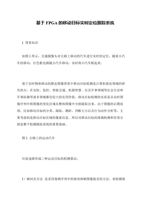
如图1所示,交通摄像头对公路上移动的汽车进行实时的定位,随着小汽车的移动,红色框也跟随小汽车移动,实时将小汽车框起来。
基于实时物体移动的静态图像背景中移动目标检测是计算机视觉领域的研究热点,在安防、监控、智能交通、机器智慧、以及军事领域等社会生活和军事防御等诸多领域都有较大的实用价值。
移动目标检测的实质是从实时图像序列中将图像的变化区域从整体图像中分割提取出来。
由于图像的后期处理,比如移动目标的分类、跟踪、测距、判断大小以及行为动作分析等,主要考虑的是移动目标区域的像素信息,所以对移动目标的准确检测和有效分割是整个检测跟踪系统的重要基础。
图1 公路上的运动汽车
目前逐渐形成三种运动目标的检测算法:
1)帧间差分法是采用视频序列中的相邻两帧图像做差的方法,来检测视。
- 1、下载文档前请自行甄别文档内容的完整性,平台不提供额外的编辑、内容补充、找答案等附加服务。
- 2、"仅部分预览"的文档,不可在线预览部分如存在完整性等问题,可反馈申请退款(可完整预览的文档不适用该条件!)。
- 3、如文档侵犯您的权益,请联系客服反馈,我们会尽快为您处理(人工客服工作时间:9:00-18:30)。
e l o t ms a e smp e h mo n s o a a a e lr e a d p r a l a a ll P a d r mp e n a in i d p e l g r h r i l ,te a u t f d t r a g n at l p r l ,F GA h r wa e i lme tt s a o td.T e r a i i y e o h n mo e
中 图 分 类 号 :T 1 .2 N9 17 文 献 标 识 码 :A
M o i g t r e r c i g s s e d sg a e n F v n a g t ta k n y t m e i n b s d o PGA
W U Ch n in Z a g Ja g, HAO u Hu , HENG B YU Xio Ya B iZ o, a n (colo lc clad Ifr ai nier g ] n s nvr t,Z ej n 10 3, hn ) Sh o fEet a n nom t n E gne n , i gu U i sy h ni g2 2 1 C ia i r o i a ei a
a mo ig tr e r c i g s se b s d o P vn a g t ta kn y t m a e n F GA.T i d sg s s t e p r mi mo e f i g r c s ig.As lw n mi de e — hs ein u e h ya d d l o ma e p o e sn o ad d l -lv
利 用 计 算 机 实 现 人 类 的 视 觉 功 能 是 目 前 计 算 机 领 域 中 最 热 门 的 课 题 之 一 [。基 于 视 频 的 目标 检 测 与 跟 踪 】 I
列 , 算 出 运 动 目标 的 运 动 参 数 , 时 也 为 后 继 的 目标 计 同 行 为 理 解 做 准 备 。该 系 统 以 获 取 视 频 序 列 中 的 运 动 目标
c mpe ih-lv l l o t ms u e o lx h g e e ag r h s Nis I o — o e fr C a g a e p o r mmi g t e r s le i o I f c r o l n u g r g a s t n o b e ov d.T e mo e ig n e iain r h d l a d r a z t a e n l o
摘 要 :为 了 解 决 基 于 P C机 的 视 频 动 态 目标 跟 踪 实 时 性 瓶 颈 问 题 ,设 计 出 一 种 基 于 F G 的 动 PA
态 目标 跟 踪 系统 。 设 计 遵 循 图 像 处 理 金 字 塔 模 型 , 对 低 层 和 中层 算 法 简 单 、 据 量 大 且 存 在 一 定 并 针 数 行 性 等 特 点 采 用 F G 硬 件 实现 , 而 高 层 较 复 杂 算 法 使 用 No I软 核 进 行 C语 言 编 程 。 整 个 设 计 采 PA isI
用 V ro — D ei g H L对 算 法 完成 建模 与 实现 , 在 Q A T S I 上 进 行 了综 合 、 线 等 工作 , l 并 U R U I 布 最后 以 A t a lr e
公 司 的 D 2开 发 板 为 硬 件 平 台 实 现 了 整 个 系 统 。 E
关 键 词 :F G 视 觉 跟 踪 ; ei g HD 动 态 目标 ; o I P A; V ro — L; l NisI
Ap ia i f It gr t Ci ut pl t c on o n e aed r i c s
基于 F G 的动 态 目标跟踪系统设计 PA
吴长 江 , 不 贿 , 博 , 小 燕 赵 郑 于
( 苏 大 学 电气 信 息 工 程 学 院 , 苏 镇 江 221) 江 江 10 3
ahee y V ro — D ,ad snhs n lc& o t ae cmp td i u r s1 sf ae pa o .Fnl ,ti ds n i c i d ue r o l e n Q a u I o w r lfr s e t t tm ia y hs ei m— l g
Ab ta t I r e o o e c me t e b t e e k o e l i n s r c : n o d r t v r o h o t n c f r a -t l me i mo i g tr e t c i g s se b s d o C,ti a e e in vn ag t r kn ytm a e n P a h s p p r d sg s
技 术 是计 算 机 视 觉 领 域 中最 主要 的 研 究 方 向之 一 , 在 科 学 研 究 和 工 程 应 用 中 都 有 十 分 诱 人 的 前 景 [ 4, 要 2 ]主 - 有 :1 智 能 视 频 监 控 系 统 ;2 图 像 压 缩 ;3 工 业 机 器 人 () () ()
