压力机说明书
北方工具+设备5速小型钻嘴压力机说明书

5-SpeedMINI DRILL PRESS OWNER'S MANUALItem # 155300WARNING:Read carefully and understand all INSTRUCTIONS before operating. Failure to follow the safety rules and other basicsafety precautions may result in serious personal injury.Thank you very much for choosing a NORTHERN TOOL+ EQUIPMENT CO., INC. Product! For future reference, please complete the owner's record below:Model: _______________ Purchase Date: _______________Save the receipt, warranty and these instructions. It is important that you read the entire manual to become familiar with this product before you begin using it.This machine is designed for certain applications only. Northern Tool + Equipment cannot be responsible for issues arising from modification. We strongly recommend this machine is not modified and/or used for any application other than that for which it was designed. If you have any questions relative to a particular application, DO NOT use the machine until you have first contacted Northern Tool + Equipment to determine if it can or should be performed on the product.For technical questions please call 1-800-222-5381.INTENDED USEThis mini drill press is designed for drilling in metal or wooden pieces.TECHNICAL SPECIFICATIONSDescription SpecificationsMotor:1/3 HPVolts:120VSpeed:620 - 3100 RPMChuck Size:1/2”Swing:8"Stroke:2"Drilling Capacity:1/2”Work tabel:65/8" x 69/16"Work base:115/8" x 71/3"Ship Weight:42 lbsFailure to follow all instructions listed below may resultWARNING!Read and understand all instructions.that common sense and caution are factors which cannot be built into this product, but must be supplied by the operator.SAVE THESE INSTRUCTIONSWORK AREA• Keep work area clean, free of clutter and well lit. Cluttered and dark work areas can cause accidents.• Do not use your tool where there is a risk of causing a fire or an explosion; e.g. in the presence of flammable liquids, gasses, or dust. Power tools create sparks, which may ignite the dust or fumes.• Keep children and bystanders away while operating a power tool. Distractions can cause you to lose control, so visitors should remain at a safe distance from the work area.12• Be aware of all power lines, electrical circuits, water pipes and other mechanical hazards in your work area, particularly those hazards below the work surface hidden from the operator's view that may be unintentionally contacted and may cause personal harm or property damage.• Be alert of your surroundings. Using power tools in confined work areas may put you dangerously close to cutting tools and rotating parts.SAFETYWARNING!Always check to ensure the power supply corresponds to the voltage on the rating plate.• Do not abuse the cord. Never carry a portable tool by its power cord, or yank tool or extension cords from the receptacle. Keep power and extension cords away from heat, oil, sharp edges or moving parts. Replace damaged cords immediately. Damaged cords may cause a fire and increase the risk of electric shock.• Grounded tools must be plugged into an outlet properly installed and grounded in accordance with all codes and ordinances. Never remove the grounding prong or modify the plug in any way. Do not use any adapter plugs. Check with a qualified electrician if you are in doubt as to whether the outlet is properly grounded. • Double insulated tools are equipped with a polarized plug (one blade is wider than the other). This plug will fit in a polarized outlet only one way. If the plug does not fit fully in the outlet, reverse the plug. If it still doesn't fit, contact a qualified electrician to install a polarized outlet. Do not change the plug in any way.• Avoid body contact with grounded surfaces such as pipes, radiators, ranges, and refrigerators. There is an increase risk of electric shock if your body is grounded.• When operating a power tool outside, use an outdoor extension cord marked “W-A” or “W.” These cords are rated for outdoor use and reduce the risk of electric shock.• Extension Cord Use: A. Use only 'Listed' extension cords. If used outdoors, they must be marked “For Outdoor Use.” Those cords having 3-prong grounding type plugs and mating receptacles are to be used with grounded tools. B. Replace damaged or worn cords immediately.C. Check the name plate rating of your tool. Use of improper size or gauge of extension cord may cause unsafe or inefficient operation of your tool. Be sure your extension cord is rated to allow sufficient current flow to the motor. For the proper wire gauge for your tool, see chart.If in doubt, use larger cord. Be sure to check voltage requirements of the tool to your incoming power source.• Do not expose power tools to rain or wet conditions. Water entering a power tool will increase the risk of electric shock.• Do not let your fingers touch the terminals of plug when installing to or removing from the outlet.• Ground fault circuit interrupters. If work area is not equipped with a permanently installed Ground Fault Circuit Interrupter outlet (GFCI), use a plug-in GFCI between power tool or extension cord and power receptacle.PERSONAL SAFETY • Stay alert, watch what you are doing and use common sense when operating a power tool. Do not use a power tool while you are tired or under the influence of drugs, alcohol or medication. A moment of inattention while operating power tools may result in serious personal injury.• Dress properly. Do not wear loose clothing, dangling objects, or jewelry. Keep your hair, clothing and gloves away from moving parts. Loose clothes, jewelry or long hair can be caught in moving parts. Air vents often cover moving parts and should be avoided.• Use safety apparel and equipment. Use safety goggles or safety glasses with side shields which comply with current national standards, or when needed, a face shield. Use as dust mask in dusty work conditions.This applies to all persons in the work area. Also use non-skid safety shoes, hardhat, gloves, dust collection systems, and hearing protection when appropriate.• Avoid accidental starting. Do not carry the power tool with your finger on the switch. Ensure the switch is in the off position before plugging tool into power outlet. In the event of a power failure, while a tool is being used, turn the switch off to prevent surprise starting when power is restored.• Do not overreach. Keep proper footing and balance at all times.• Remove adjusting keys or wrenches before connecting to the power supply or turning on the tool. A wrench or key that is left attached to a rotating part of the tool may result in personal injury.• Never place your fingers in a position where they could contact the drill or other cutting tool if the workpiece should unexpectedly shift or your hand should slip.• Whenever possible, position the WORKPIECE to contact the left side of the column if it is too short or the table is tilted, clamp solidly to the table. Use table slots or clamping ledge around the outside edge of the table.• When using a drill press VISE, always fasten it to a table.• Never climb on or allow others to climb on the drill press table; it could break or pull the entire drill press down.• Turn the motor Switch OFF and put away the Switch Key when leaving the drill press.• To avoid injury from thrown work or tool contact, do NOT perform layout, assembly, or setup work on the table while the cutting tool is rotating.TOOL USE AND CARE• Do not force the tool. Tools do a better and safer job when used in the manner for which they are designed. Plan your work, and use the correct tool for the job.• Never use a tool with a malfunctioning switch. Any power tool that cannot be controlled with the switch is dangerous and must be repaired by an authorized service representative before using.• Disconnect power from tool and place the switch in the locked or off position before servicing, adjusting, installing accessories or attachments, or storing. Such preventive safety measures reduce the risk of starting the power tool accidentally.• Secure work with clamps or a vise instead of your hand to hold work when practical. This safety precaution allows for proper tool operation using both hands.• Store idle tools. When tools are not is use, store them in a dry, secure place out of the reach of children. Inspect tools for good working condition prior to storage and before re-use.• Use only accessories that are recommended by the manufacturer for your model. Accessories that may be suitable for one tool may create a risk of injury when used on another tool.• Keep guards in place and in working order.For your own safety, do not try to use your drill press or plug it in until it is completely assembled and installed according to the instructions, read and understood this Instruction manual:• Your drill press must be bolted securely to a workbench. In addition, if there is any tendency for your drill press to move during certain operations, bolt the workbench to the floor.• This drill press is intended for use in dry conditions, indoor use only.• Always keep hands out of the path of a drill bit. Avoid awkward hand positions where a sudden slip could cause your hand to move into the drill bit.• Do not install or use any drill bit that exceeds 175 mm (7") in length or extends 150 mm (6") below the chuck jaws. They can suddenly bend outward or break.• Do not use wire wheels, router bits, shaper cutters, circle (fly) cutters, or rotary planers on this drill press. • When cutting a large piece of material make sure it is fully supported at the table height.• Do not perform any operation freehand. Always hold the workpiece firmIy against the table so it will not rock or twist. Use clamps or a vice for unstable workpieces.• Make sure there are no nails or foreign objects in the part of the workpiece to be drilled.• Do not touch the bit or chips. Drill bits and cuttings are hot immediately offer drilling.• Never reach around or under the working head, or grab the chuck key to stop the drill press.• Make sure the drill press speed is appropriate for both the type of material and bit size you are using.34• Clamp workpiece or brace against the left side of the column to prevent rotation. If it is too short or the table is tilted, clamp solidIy to the table and use the fence provided. • If the workpiece overhangs the table such that it will fall or tip if not held, clamp it to the table. Provide auxiliary support. • Make sure all clamps and locks are firmly tightened before drilling. • Securely lock the head and table support to the column, and the table to the table support before operating the drill press. • Never turn your drill press on before clearing the table of all objects. (tools, scraps of wood, etc.) • Before starting the operation, jog the motor switch to make sure the drill bit does not wobble or vibrate. • Let the spindle reach full speed before starting to drill. If your drill press makes an unfamiliar noise or if it vibrates excessively, stop immediately, turn the drill press off and unplug. Do not restart until the problem is corrected. • Do not perform layout assembly or set up work on the table while the drill press is in operation. • Make sure the spindle has come to a complete stop before touching the workpiece. • To avoid injury from accidental starting, always turn the switch "OFF" and unplug the drill press before installing or removing any accessory or attachment or making any adjustment. • Keep guards in place and in working order. • Use onIy self-ejecting type chuck key as provided with the drill press. • Do not try to drill material too small to be securely held.• Use the drill press in a well-lit area and on a level surface clean and smooth enough to reduce the risk of trips, slips, or falls. Use it where neither the operator nor a casual observer is forced to stand in line with a potential kickback.WARNING! For your own safety, do not attemp to operate your drill press until it is completely assembled and installed according to the instructions and until your have read and understand the following:1. General Safety Instructions for Power Tools2. Getting to Know Your Drill Press3. Basic Drill Press Operation4. Adjustments5. MaintenanceUNPACKINGOn receipt, carefully unpack the components ensuring that no damage was suffered in transit, and that all following parts are accounted for.1. Table Support2. Support Lock Handle3. Column4. Base5. Support column6. Screw Hex HD M8 x 207. Table Bevel Lock Screw8. Table9. Head Arm Check the parts againts the above list and refer to the diagrams. Should there be any deficiencies or damage, you should contact Northern Tool + Equipment.5GETTING TO KNOW YOUR DRILL PRESSASSEMBLY1.Install (3) M8 x 20 bolts in each hole through Column Support and base and tighten with wrench.2.Slide table/support into column.3.Install support lock handle from left side into table support and tighten by hand.4.Lift head above column and slide it onto the column as possible. Align head with table and base. Using a 4mm Hex “L” wrench, tighten the head lock set screws on the head.5.Screw the feed handles into the threaded holes in the hub and tighten.6.Clean out the tapered hole in the chuck. Clean the spindle nose with a clean cloth. Push the chuck up on the spindle nose as far as possible. Lightly tap the nose of the chuck with a piece of wood to ensure proper fitting of the chuck on the spindle.7.Install M5 x 12 pan HD screw in hole located in guard and attach knob, turning until tighten.8.Choose speed for drilling operation, and install belt to correct position for desired speed. Loose belt tension lock handle and turn the motor counterclockwisely to apply tension to the belt. Tighten belt tension lock handle.OPERATION1.Before using this machine, the operator should carefully read over this operation manual to acquaint himself with the construction, controls and driving system of the machine.2.All of the Ball Bearing are packed with grease at the factory. They require no further lubrication. Periodically lubricate the grooves in the spindle and the rack (teeth of the quill).3.Install drill into chuck far enough to obtain maximum gripping of the chuck jaws. Make sure that the drill is centered in the chuck. Tighten the drill sufficiently, so that it does not slip while drilling. Turn the chuck key clockwise to tighten, counter-clockwise to loosen the drill bit.4.The drilling depth may be controlled by pointer and depth scale or by the two stop nuts, on the feed stop rod.1. Pulley-Guard2. Belt Tension Lock Handle3. Head Lock Set Screws4. Support-Table5. Column-support6. Support-Lock7. Base8. Spring-Cap9. Depth-Scale Indicator 10. Depth-Scale 11. Column 12. Bevel Scale 13. Table Lock Set Screw 14. Table 15. Feed Handles 16. Chuck 17. Feed Stoop Rod 18. Stop Nuts 19. Switch 20. Stop-Motor Spring Motor Stop65.To position the table, loosen support lock handle, move the table to the desired position and retighten support lock.To tilt table, loosen the bevel lock, tilt the table to desired position on the bevel scale and retighten bevel lock.6.After drilling a hole, release the feed handle to have the spindle sleeve return to its original position.7.In case of any trouble or abnormal noise arising during operation, stop the motor at once and find out the cause.8.After operation, remove chips and dirt on the machine and cover all the unpainted surfaces with oil to prevent them from rusting. Turn off the power supply for safety.WARNING!For your own safety, turn switch “off” and remove plug from power source outlet before maintaining or lubricating your drill press.WARNING! To avoid shock or fire hazard, if the power cord is worn or cut, or damaged in any way, haveit replaced.WARNING! Make sure this tool is disconnected from its power source before attempting any maintenance,cleaning, or inspection.• Maintain your tools.It is recommended that the general condition of any tool be examined before it is used.Keep your tools in good repair by adopting a program of conscientious repair and maintenance in accordance with the recommended procedures found in this manual. If any abnormal vibrations or noise occurs, turn the tool off immediately and have the problem corrected before further use. Have necessary repairs made by qualified service personnel.• Keep cutting tools sharp and clean.Properly maintained cutting tools with sharp cutting edges are less likely to bind and are easier to control. Keep handles dry, clean, and free from oil and grease. • e only soap and a damp cloth to clean your tools. Many household cleaners are harmful to plastics and other insulation. Never let liquid get inside a tool.WARRANTY One-Year Limited Warranty For warranty questions, call 1-800-222-53817FIGURE 1DIAGRAM & PARTS LIST8FIGURE 29Northern Tool + Equipment Co.,2800 Southcross Drive West P .O. Box 1499 Burnsville, MN 55337-0499Made in China。
电脑全自动水泥恒应力压力机使用说明书

电脑全自动水泥恒应力压力机使用说明书一、产品简介电脑全自动水泥恒应力压力机是一种专业用于测定水泥材料的抗压强度的仪器。
该压力机采用先进的电脑控制系统,能够实现全自动操作,具备高精度、高效率和稳定性好的特点。
本说明书将详细介绍该压力机的结构、工作原理以及正确的操作方法。
二、产品结构电脑全自动水泥恒应力压力机由以下几个主要部分组成:1. 主机:包括机架、液压系统、电控系统等。
2. 受力装置:用于夹持水泥试样并施加压力。
3. 电控系统:用于控制压力机的运行和数据处理。
三、工作原理电脑全自动水泥恒应力压力机的工作原理是通过液压系统将压力传递给受力装置,使其施加于水泥试样上,从而测定水泥的抗压强度。
电控系统能够实时监测压力的变化,并将数据传输至电脑进行处理和分析。
四、操作步骤1. 准备工作a. 检查压力机的电源和液压系统是否正常工作。
b. 确保试样制备完好并符合相应标准。
c. 清洁试样夹持装置,并确保试样夹持装置处于正常工作状态。
2. 开机操作a. 按下电源按钮,启动电脑和压力机。
b. 进入电控系统界面,选择合适的实验模式。
3. 设置参数a. 根据试验标准和试样要求,在电控系统上设置相应的参数,如加载速率、加载范围等。
b. 确保设置的参数符合试验要求,并进行确认。
4. 试样安装a. 将试样放入试样夹持装置中,并调整好夹持装置的位置。
b. 确保试样夹持牢固,并不会移动或翻倒。
5. 开始实验a. 点击电控系统界面上的“开始”按钮,启动实验过程。
b. 电控系统将自动施加压力,并持续记录压力和变形数据。
6. 实验完成a. 当试样断裂或压力机达到设定的最大压力时,实验结束。
b. 结束实验后,关闭电源按钮,停止电控系统和压力机的工作。
五、注意事项1. 操作人员应熟悉该压力机的结构、工作原理及操作步骤,并严格按照说明书进行操作。
2. 在操作过程中,应保持试验台面整洁,避免杂物或灰尘进入压力机系统。
3. 试样的制备应符合相应的标准,以确保实验结果的准确性。
说明书 - 50T液压压力机

本科毕业论文(设计)题 目 50T 液压压力机机械设计 学生姓名 王豪专业名称 机械设计制造及其自动化 指导教师 王伟年 月 日教学单位宝鸡文理学院学生学号 201294014251编 号 JX2016JZ425150T液压压力机机械设计摘要在现今社会,液压传动已经是一门相对比较成熟的技术,已经广泛的应用于机械制造、工程机械、农业机械、汽车制造以及锻压等行业。
而其在实现高速、高压、高效率、大功率、经久耐用、噪声低,高度集成化等各项要求的显著优势使得这门技术有着更加广阔的发展前景。
本次在对液压传动发展和液压传动的工作原理作了一个简要说明,与此同时,更是对液压技术在锻压机械中的一个典型应用——4柱液压机的液压系统进行了全面的设计计算。
其内容主要包括:1 液压传动系统方案的分析、比较和确定;2 确定并绘制系统原理图,液压机结构的设计;3 完成液压缸的设计;4 液压系统中各主要参数的计算;5 各种液压元件的选择;6 设计并绘制成系统装配图;在500KN液压机液压系统执行元件液压缸的设计中,利用在前文系统设计中所校核过的如活塞直径D(ΦAL)、活塞杆直径d(ΦMM)等参数,我们对液压油缸的各主要零部件进行了详细的结构设计,并绘制了它们的零件图及液压油缸装配图。
在本设计中,所有图纸均使用绘图软件CAXA(电子图板V2版)绘制而成,使得图纸更加清晰,一目了然。
关键字:液压机;液压系统设计;液压油缸;CAXAABSTRACTAbstract:Nowadays, hydraulic drive is a technique becoming mature, what has been applied in Manufacture, Engineering Machinery, Farm Machinery, Car Manufacturing, and Forging Presses etc. Moreover, it has a so salient advantage in actualize high pressure, high speed, hight-power, hight efficiency, low yawp, longevity and hight integration that it could develope much faster then others.After the phylogeny of the hydraulic drive and the working theory have been introduced in this paper, we have do a fully design for the system of the single column hydraulic presses which is a type application in Forging Presses.It includes:1 Analysing, comparing and confirming the project of hydraulic drive;2 Confirming and drawing the system blueprint;3 Drawing a blueprint of the cell loop of the integration block;4 Accounting, checking and normalizing the mainly parameter in the hydraulic system5 Choosing the different kinds of hydraulic component6 Designing how to rig out all the parts of the system and then draw a blueprint to reflect it.In the design of the working part of the 50KN system, cylinder, we have do a particular frame design in using the parameter as the diameter of the piston D(ΦAL) and the diameter of the pole d(ΦMM).In this project, to make blueprint more clearly and even be clear at a glance, we draw the entire blueprint in software CAXA.Keywords: Single Column HydraulPresses; The Design of Hydraulic System;Hydraulic cylinder; CAXA目录1压力机概述-------------------------------------------------------------- 11.1压力机发展的概况 -------------------------------------------------- 11.2压力机工作原理 ---------------------------------------------------- 21.2.1压力机功能简介 ---------------------------------------------------------------------------------------- 21.2.2压力机的工作原理简介 ----------------------------------------------------------------------------- 4 2液压机总体结构设计 ----------------------------------------------------------------------------------------------------- 42.1压力机总体设计结构及要求-------------------------------------------------------------------------------- 42.2 立柱的强度计算 ------------------------------------------------------------------------------------------------- 42.3 横梁的强度计算 ------------------------------------------------------------------------------------------------- 52.4油箱的设计---------------------------------------------------------------------------------------------------------- 53.压力机的液压系统设计 ------------------------------------------------------------------------------------------------ 63.1液压传动的优缺点----------------------------------------------------------------------------------------------- 63.2设计参数和应满足的条件------------------------------------------------------------------------------------ 73.2.1负载分析初步确定各工况的负载和速度 --------------------------------------------------- 83.2.2液压介质的选择 ---------------------------------------------------------------------------------------- 83.3液压系统的设计 -------------------------------------------------------------------------------------------------- 93.3.1确定液压系统方案 ------------------------------------------------------------------------------------ 93.3.2 液压原理图的拟定---------------------------------------------------------------------------------- 114 液压系统的计算和液压元件的选择---------------------------------------------------------------------------- 124.1 液压缸的选择 --------------------------------------------------------------------------------------------------- 124.1.1主缸的选择---------------------------------------------------------------------------------------------- 124.1.2顶出缸的选择 ------------------------------------------------------------------------------------------ 134.2液压泵站 ------------------------------------------------------------------------------------------------------------174.2.2液压泵的选择 ------------------------------------------------------------------------------------------ 184.2.3液压泵的压力 -------------------------------------------------------------------------------------------204.3活塞 --------------------------------------------------------------------------------------------------------------------204.3.1活塞杆的计算 -------------------------------------------------------------------------------------------204.3.2活塞的材料及要求 ---------------------------------------------------------------------------------- 224.3.3活塞杆的设计与计算------------------------------------------------------------------------------- 224.3.4活塞杆材料及技术要求 --------------------------------------------------------------------------- 234.4电动机的选择 ---------------------------------------------------------------------------------------------------- 244.5液压阀的选择 ---------------------------------------------------------------------------------------------------- 244.5.1 方向控制阀的选择---------------------------------------------------------------------------------- 244.5.2压力控制阀的选择 ---------------------------------------------------------------------------------- 244.5.3流量控制阀的选择 ---------------------------------------------------------------------------------- 244.6辅助元件的设计 -------------------------------------------------------------------------------------------------254.6.1 滤油器的选择 ------------------------------------------------------------------------------------------254.6.2油管尺寸的确定 ---------------------------------------------------------------------------------------254.6.3油箱容量的选择 ---------------------------------------------------------------------------------------265 液压系统性能验算------------------------------------------------------------------------------------------------------ 296 总结 -----------------------------------------------------------------------------------------------------------------------------31参考文献 -------------------------------------------------------------------------------------------------------------------------321压力机概述1.1压力机发展的概况相对于机械传动来说,液压传动是一门比较新的技术,如果从17世纪中叶巴斯卡提出静压传递原理、18世纪末英国制成世界上第一台水压机算起的话,液压传动技术也已有二三百年历史了。
液压压力机使用说明书
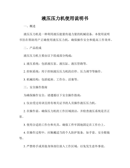
液压压力机使用说明书一、概述液压压力机是一种利用液压能量传递力量的机械设备。
本使用说明书旨在帮助用户正确使用液压压力机,确保操作安全和提高工作效率。
二、产品组成液压压力机主要由以下组成部分构成:1. 液压系统:包括液压泵、液压缸、液压管路等。
2. 控制系统:用于控制液压压力机的启停、压力调节等操作。
3. 机械结构:包括底座、工作台、活塞等。
三、安全操作指南为确保操作安全,请遵循以下安全操作指南:1. 仅由受过培训且持有相关证书的人员操作液压压力机。
2. 在操作前,确保压力机的工作区域清洁,并检查液压系统是否正常。
3. 使用合适的工作台和夹具,确保工件牢固地固定在工作台上。
4. 在操作过程中,应佩戴适当的个人防护装备,如手套、安全眼镜等。
5. 严禁将手或其他身体部位放入工作区域,以免发生意外事故。
6. 在操作过程中,应随时关注液压压力机的运行状态,如有异常情况应立即停机检修。
7. 操作结束后,应及时关闭液压系统的电源,并进行必要的维护保养。
四、操作步骤1. 打开液压系统电源,确保液压泵正常运行。
2. 使用液压调压阀或压力控制器设置所需的工作压力。
3. 将待加工的工件放置在工作台上,并用合适的夹具固定。
4. 操作控制系统中的启动按钮,使液压压力机开始工作。
5. 在工作过程中,根据需要调整工作压力和工作时间。
6. 完成加工后,停止液压压力机的工作,关闭液压系统电源。
五、维护保养1. 每天使用前,检查液压系统的油位,并确保油液清洁。
2. 定期检查液压系统的密封件,如有磨损或老化应及时更换。
3. 液压压力机使用一段时间后,应进行清洗和润滑,确保机械结构的正常工作。
4. 定期检查液压泵、液压缸等关键部件的工作状态,如有异常应及时修理或更换。
六、故障排除在使用过程中,如果遇到以下故障,请立即停机并采取相应措施:1. 压力不稳定:检查液压系统中是否有漏油或气泡,排除故障后再次启动。
2. 压力过高或过低:调节液压调压阀或压力控制器,使压力处于正常范围。
yA32一200A四柱压力机使用说明书

yA32一200A四柱压力机使用说明书
yA32一200A四柱压力机适用于各种可塑性材料的压制工艺,如弯曲、翻边等、也能从事校正、压装、塑料制品压制成型工艺。
本机器具有独立的动力机构及电气系统,并采用按钮集中控制,可实现调整和工作两种操作方式。
本机器的工作压力、压制速度、行程范围均可根据工艺需要进行调整。
并完成定压成型和定程成型两种工艺方式,在压制后具有保压延时和自动回程动作。
不了解机器结构性能或操作程序者不能擅自开机器:机器在工作过程中,不应进行检修和调整模具:检修调整模具应停机并用垫块支
撑滑块。
当机器发现严重漏油或其他异常(如动作不可靠、燥声大、振动等)应停车分析原因,设法排除,不得带病生产:不得超载或超过最大偏心距使用:严禁超过滑块最大行程,模具闭合高度最小不得小于480毫米:电气设备接地必须牢固可靠。
严防充液阀固定螺栓带松工作。
要求初使用半个月检查次有无松动,若发现松动要及时紧固车实,正常使用两个月检查一次。
Arcan CP500 50吨手动车间压力机说明书

SHOP PRESSASSEMBLY INSTRUCTIONSCP500 - 50 TON MANUAL SHOP PRESS WITH WINCHPRESS SPECIFICATIONSArcan Model No. A B C D E F G H I CP50074"35"29.75"13" 6.75" 1.25"Y Y Y(2)A - Total HeightB - Inside WidthC - Press Feet LengthD - Bed WidthE - Stroke (ram travel distance from fully retracted position to fully extended position)F - Pin DiameterG - PB WinchH - Sliding HeadI - Press Plates IncludedP.O. Box 58 Travelers Rest, SC 29690 Phone: (800) 879-7316 Fax: (864) 834-0073© Copyright 2007, Arcan Professional ToolsSAFETY INFORMATIONThis symbol alerts you to the possibilityof serious injury or death if instructionsare not followed.This symbol alerts you to the possibilityof damage to or destruction of equipmentif instructions are not followed.Failure to heed these warnings may result in lossof load, damage to the press and/or failureresulting in property damage, personal or fatal injury. This operating manual contains important details concerning the safe operation of this tool. The user must read and understand these details before any use of the tool. This manual must be retained for future reference.• Read, study, and understand all instruction manuals packed with this press before operating.• Always wear safety goggles.• Parts being pressed may splinter, shatter, or be ejected from the press at a dangerous rate of speed. Because of the variety of pressapplications, it is your responsibility to always use adequate guardsand wear eye protection and heavy protective clothing when operatingthepress.• Visual inspection should be made before each use of the press, checking for signs of cracked welds, bent bed pins, loose or missing bolts, leaks, or any other structural damage.• Do not go near leaks. High pressure oil can puncture skin and cause serious injury, gangrene, or death. If injured, seek emergency medical help. Immediate surgery is required to remove oil.• Keep hands and fingers out of the press and away from parts that may shift and pinch. Do not stand in front of work area when load is applied. • Always use an accurate pressure gauge to measure pressing force.• Do not exceed the rated capacity of this press.• Never tamper with hydraulic system pressure settings.• Do not substitute bolts, pins or any part of the components. Use only genuine factory replacement parts.• Always center load on ram plunger. Offset loads can damage ram and may cause load to eject at a dangerous rate of speed.• Remove all loads from press bed before attempting to adjust bed height.Beware of possibility of falling bed.• Press only on loads supported by press bed and included press plates.Do not support loads on floor or press frame.• When using any accessories such as arbor plates, be certain they are centered on press bed and are in full contact with press bed.• Before applying load, be certain all press bed supporting pins are fullyengaged.• Always use a bearing shield when pressing bearings. Use caution when positioning work to be pressed to ensure that the item that is to bepressed cannot be dislodged or broken during press work. This mayresult in the item being ejected from the press at a dangerous rate ofspeed.• Release hydraulic pressure before loosening any fittings.• Maintain proper hydraulic fluid levels.• Do not make any alterations to the press.OWNER/USER RESPONSIBILITYThe owner and/or user must have an understanding of the manufacturer's operating instructions and warnings before using this press. Personnel involved in the use and operation of equipment must be careful, competent, trained, and qualified in the safe operation of the equipment and its proper use when servicing motor vehicles and their components.Warning information should be emphasized and understood.If the operator is not fluent in English, the manufacturer's instructions and warnings must be read to and discussed with the operator in the operator's native language by the purchaser/owner, making sure thatthe operator comprehends its contents.Owner and/or user must study and maintain for future reference the manufacturer’s instructions. Owner and/or user is responsible for keeping all warning labels and instruction manuals legible and intact. Replacement labels and literature are available from the manufacturers.INSPECTIONVisual inspection of the shop press should be made before each use of the press, checking for damaged, loose or missing parts. Each press must be inspected by a manufacturer’s repair facility immediately if subjected to an abnormal load or shock. Any press which appears to be damaged in any way, is found to be badly worn, or operates abnormally must be removed from service until necessary repairs are made by a manufacturers's authorized repair facility. It is recommended that an annual inspection of the press be made by a manufacturer’s authorized repair facility and that any defective parts, decals or warning labels be replaced with manufacturer’s specified parts. A list of authorized repair facilities is available from the manufacturer. SAFETY INSTRUCTIONS• CHECK YOUR LOCAL, STATE AND FEDERAL REGULATIONS REGARDING THE SAFE USE OF THIS EQUIPMENT.• Your safety is a top priority. Please handle equipment with care.• Fully retract unit and remove all items from the press bed frame.• Support the press bed and remove the pins.• Raise or lower bed to desired height and reinstall press pins. Be certain pins are fully engaged in the parallel flanges of the upright columns.• Position press on a flat, level, hard surface, preferably concrete.Make sure all nuts and bolts are tight.• Clear the area of bystanders, especially small children, before using.• Set the press bed to the required height. The press is most effective when the work piece is located 1 inch below the ram’s retracted position.The compression stroke can include the entire 5 inch working range.• The press is designed to exert a force on anything which is positioned beneath its ram. The work piece can be ejected from under the ram ata high rate of speed and can injure someone.• Pressing Bearings: It is essential that you use the bearing shield when pressing bearings are on or off.OPERATION1. Press beds are adjustable up and down to fully take advantageof available ram travel and numerous work pieces.2. Slowly open release valve on power unit. With the power unitin its stored position, remove all items from the press bed.3. Be sure press bed is supported properly and remove press bed pins.4. Raise or lower press bed to desired height, and reinstall pressbed pins. Be certain pins are completely through both sidesof frame, as these pins are the major support mechanism for the bed.We want to know if you have any problems with our products.If you are missing any parts or find any damage, call Arcan directly,and we will remedy the situation. Please do not call the store whereyou purchased this product.Phone: (800) 879-7316Email:**********************。
原位压力机使用说明书
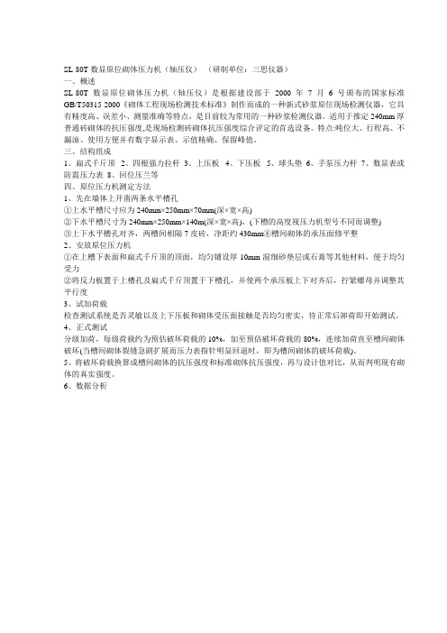
SL-80T数显原位砌体压力机(轴压仪)(研制单位:三思仪器)一、概述SL-80T数显原位砌体压力机(轴压仪)是根据建设部于2000年7月6号颁布的国家标准GB/T50315-2000《砌体工程现场检测技术标准》制作而成的一种新式砂浆原位现场检测仪器,它具有精度高、误差小、测量准确等特点,是目前较为常用的一种砂浆检测仪器。
适用于推定240mm厚普通砖砌体的抗压强度,是现场检测砖砌体抗压强度综合评定的首选设备。
特点:吨位大、行程高、不漏油、使用方便并有数字显示表、示值精确、保留峰值。
三、结构组成1、扁式千斤顶2、四根强力拉杆3、上压板4、下压板5、球头垫6、手泵压力杆7、数显表或防震压力表8、回位压兰等四、原位压力机测定方法1、先在墙体上开凿两条水平槽孔①上水平槽尺寸应为240mm×250mm×70mm(深×宽×高)②下水平槽尺寸为240mm×250mm×140m(深×宽×高),(下槽的高度视压力机型号不同而调整)③上下水平槽孔对齐,两槽间相隔7皮砖,净距约430mm④槽间砌体的承压面修平整2、安放原位压力机①在上槽下表面和扁式千斤顶的顶面,均匀铺设厚10mm湿细砂垫层或石膏等其他材料,便于均匀受力②将反力板置于上槽孔及扁式千斤顶置于下槽孔,并使两个承压板上下对齐后,拧紧螺母并调整其平行度3、试加荷载检查测试系统是否灵敏以及上下压板和砌体受压面接触是否均匀密实,待正常后卸荷即开始测试。
4、正式测试分级加荷,每级荷载约为预估破坏荷载的10%,加至预估破坏荷载的80%,连续加荷直至槽间砌体破坏(当槽间砌体裂缝急剧扩展而压力表指针明显回退时,即为槽间砌体的破坏荷载)。
5、将破坏荷载换算成槽间砌体的抗压强度和标准砌体抗压强度,再与设计值对比,从而判明现有砌体的真实强度。
6、数据分析。
压力机设计说明书
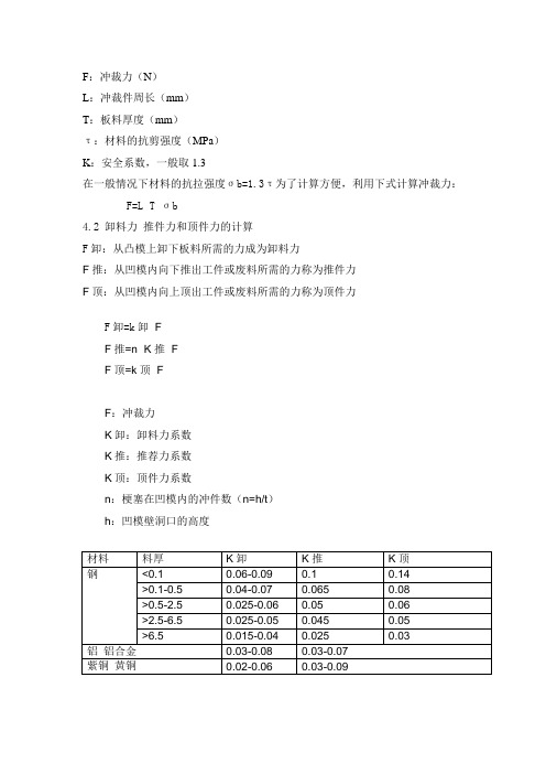
F:冲裁力(N)L:冲裁件周长(mm)T:板料厚度(mm)τ:材料的抗剪强度(MPa)K:安全系数,一般取1.3在一般情况下材料的抗拉强度σb=1.3τ为了计算方便,利用下式计算冲裁力: F=L×T×σb4.2 卸料力推件力和顶件力的计算F卸:从凸模上卸下板料所需的力成为卸料力F推:从凹模内向下推出工件或废料所需的力称为推件力F顶:从凹模内向上顶出工件或废料所需的力称为顶件力F卸=k卸×FF推=n×K推×FF顶=k顶×FF:冲裁力K卸:卸料力系数K推:推荐力系数K顶:顶件力系数n:梗塞在凹模内的冲件数(n=h/t)h:凹模壁洞口的高度材料料厚K卸K推K顶钢<0.1 0.06-0.09 0.1 0.14>0.1-0.5 0.04-0.07 0.065 0.08>0.5-2.5 0.025-0.06 0.05 0.06>2.5-6.5 0.025-0.05 0.045 0.05>6.5 0.015-0.04 0.025 0.03铝铝合金0.03-0.08 0.03-0.07紫铜黄铜0.02-0.06 0.03-0.094.3 压力机所需总冲压力的计算计算冲裁所需的总冲压力时,应先根据模具结构的具体情况,分析总冲压力究竟包含上述冲裁力和卸料力,推件力和顶件力中的哪几项。
采用弹压卸料装置和下初件模具时,上模在冲裁的同时还需克服卸料弹簧阻力和推动梗塞在凹模的材料的推力,于是FQ=F+F卸+F推采用弹压卸料装置和上初件模具时:FQ=F+F卸+F顶采用刚性卸料装置和下出模具时:FQ=F+F推。
100压力机说明书

YN32-100 四柱式液压机使用说明书公称力1000kN出厂编号:中华人民共和国敬告用户1.操作机器前,请详细阅读使用说明书。
不了解机器结构性能及操作程序者不得擅自开动机器及拆卸维修。
2.如需进入机器行程空间内检修或调整模具,必须在滑块下加安全支撑。
3.严禁超载、超行程及超过最大偏心距使用。
4.拆卸管路时,必须将滑块放至下死点。
5.非专业人员不得对电气线路进行拆卸、改动。
6.电气设备接地必须牢固、可靠。
目录一.外形总图二.用途和特点三.主要技术规格四.结构概述五.液压系统概述六.电气系统概述七.安装和试车八.故障和消除方法九.维修保养和安全操作规程十.易损件表及附图1.工作台俯视图2.滑块仰视图3.主缸结构图4.顶出缸结构图5.液压原理图6.电气原理图7.地基图二.用途和特点:本机器适用于可塑性材料的压制工艺,如冲裁、弯曲、翻边、薄板拉伸等。
也可从事于校正、压装、砂轮成型、冷挤金属零件成型、塑料制品及粉末制品的压制成型工艺。
本机器具有独立的动力机构和电气系统。
并采用按钮集中控制,可实现调整、手动和半自动三种操作方式。
本机器的工作压力、压制速度、行程范围均可根据工艺需要进行调整。
并能完成定压及定程成型两种工艺方式。
定压成型工艺方式在压制后具有保压、延时和自动回程动作。
三.主要技术规格:四.结构概述:本机器由主机及控制机构两大部分组成,通过管路及电气系统装臵联系起来构成完整的一体。
主机部分为机身、主缸、顶出缸三部分组成。
控制机构包括动力机构、限程装臵、管路、电气箱、操纵箱等几部分组成。
现将各部分结构和作用分述如下:(一)机身:(见外形总图)机身由上横梁、滑块、工作台、立柱、锁紧螺母及调节螺母等组成。
固定于机座上面依靠四个立柱为骨架,上横梁及工作台由锁紧螺母固定于两端。
机器精度靠调节螺母及紧固于上横梁上端的锁紧螺母来调整。
滑块与主缸活塞联接,依靠四柱作导向上下运行,内装有导向套。
滑块及工作台工作表面均有T形槽,以便安装模具,T形槽尺寸见附图1及附图2。
压力机使用说明书

压力机使用说明书使用说明书一、前言感谢您选择我们的压力机产品。
为了确保您能正确使用该产品,本使用说明书将为您详细介绍压力机的使用方法和注意事项。
在使用之前,请您认真阅读本说明书并按照要求进行操作。
二、产品概述压力机是一种用于加工金属材料的机械设备,广泛应用于工业领域。
本款压力机具有稳定的性能和高效的工作能力,经过多次优化设计,能够满足您的不同加工需求。
三、安全注意事项1. 在使用压力机之前,请务必佩戴适当的防护装备,包括防护眼镜、防护手套等。
2. 请确保压力机周围没有任何障碍物,以确保操作的安全性。
3. 使用压力机时,请保持机器平稳,并确保其底座固定牢固。
四、操作步骤及注意事项1. 打开电源开关,确保电源正常并连接稳定。
检查压力机各个部件是否完好无损。
2. 调整加工面板的高度,以适应不同加工需求。
选择合适的模具,并进行安装。
3. 将待加工的工件放置在加工面板上,并通过调整刀具位置和角度来确保加工的准确性。
4. 打开压力机控制面板上的启动按钮,启动压力机。
根据需要调节压力的大小,以达到预期的加工效果。
5. 请注意安全距离,不要将手指或其他物体靠近刀具和工件,以免发生意外伤害。
6. 加工完成后,关闭电源开关,清理加工面板和模具残留物,并及时对压力机进行保养和维护。
五、故障排除1. 压力机无法运转:检查电源连接是否正常,是否有过载保护等,必要时请联系售后服务人员进行维修。
2. 压力机运转异常声音:检查机器底座是否稳固,是否需要进行润滑保养等。
3. 压力机加工效果不理想:检查模具是否合适,是否需要进行更换或调整。
六、保养与维护1. 每次使用结束后,请进行清洁和保养,包括清除加工面板上的残留物、检查电源线路等。
2. 定期对压力机进行润滑,以确保各个部件的灵活性和正常工作。
3. 对于长时间不使用的压力机,请断开电源,并妥善存放。
七、服务支持如您在使用过程中遇到任何问题或需要进一步协助,请随时联系我们的售后服务部门。
Ageo压力机DP-R系列操作说明书
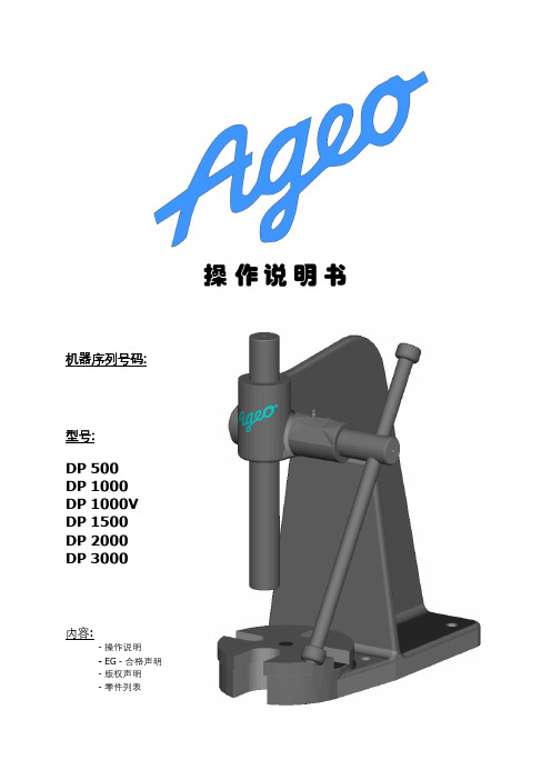
操作说明书机器序列号码:型号:DP 500DP 1000DP 1000VDP 1500DP 2000DP 3000内容:- 操作说明- EG - 合格声明- 版权声明- 零件列表目录1.简介 (2)2.安装固定压力机 (2)3.使用操作 (4)4.安全警示 (5)5.技术规格与保养维护 (6)6.配件 (8)6.1.开槽盘 (8)6.2.刀具安装孔 (符合标准 DIN 810) (9)6.3.矩形工作台 (10)6.4.压力杆扭转止动 (11)1.1.深度限制 (11)6.5.支撑架 (13)7.版权及技术文档 (14)8. EG –合格声明 (15)附件: 零件列表芯轴压力机操作说明书AGEO – DP 系列1.简介AGEO芯轴压力机是经过几十年实际应用操作所验证并被广大客户所认可的机械传动压力设备,主要适用于对转轴,插槽,套管,滚动轴承,螺栓和销钉等工件的装配和拆卸。
DP 系列压力机也可搭配其他有关刀具对工件进行弯曲,铆接和注模等加工作业,还可以针对小键槽或类似的轮廓的拉削加工。
压力机机械传动手柄的长度经过科学的衡量设计,确保一般的手劲能驱动并达到所需的工作压力。
2.安装固定压力机首先,把压力机放置在平整且足够坚固的工业地面,并用合适大小的钉销把压力机机体固定于其上。
凹凸不平或松软的安装平面会削弱压力机站立稳定性。
严重者会有挤压或剪伤人体的危险 !在吊装和运输压力机时,应严格参照有关安全操作条例和通用技术规范操作。
安全操作条例《通用操作规范》 BGV A1《起重机操作规范》 BGV D6 (VBG 9)《工具刀具操作规范》 BGR 500 , Kap. 2.8德国工业标准《起重设备和载重设备标准》 DIN 15003《环钩,质量等级5“》DIN 7540《卸扣》 DIN 821013.使用操作在首次使用压力机之前请清除机体上所有机械加工表面上的缓蚀剂。
请保留活动部件上预涂抹的薄层润滑油脂。
操纵压力机作业可以通过操作压力机机头边上的手柄或手轮完成。
250吨三梁四柱压力机说明书
250吨三梁四柱压力机说明书一、产品简介250吨三梁四柱压力机是一种用于金属材料加工的机械设备。
它采用了三梁四柱结构,具有较高的压力承载能力和稳定性,可广泛应用于冲压、模具成型、压制等工艺领域。
二、产品特点1. 高压力承载能力:250吨的压力能满足大部分金属材料加工的需求,确保产品成型的质量和精度。
2. 稳定性强:采用三梁四柱结构,保证了机器在工作过程中的稳定性和精度,有效避免了振动和变形现象。
3. 操作简便:该压力机采用先进的电气控制系统,具有直观的操作界面和易于操作的功能,操作人员能够快速上手。
4. 安全可靠:设备配置了多重安全保护装置,如过载保护、急停按钮等,确保操作人员的人身安全和设备的正常运行。
5. 精度高:该设备配备了精密的液压系统和控制系统,能够实现高精度的压力控制和产品成型。
三、产品应用领域250吨三梁四柱压力机广泛适用于以下领域:1. 冲压加工:可用于冲压成型各种金属材料的零部件,如汽车零件、家电配件等。
2. 模具成型:可用于模具的压制和成型,如塑料模具、橡胶模具等。
3. 金属加工:可用于金属板材的压制、切割、折弯等工艺。
四、使用说明1. 设备安装:在使用前需将设备固定在坚固的基础上,并进行稳定调整,确保设备平稳运行。
2. 电气接线:根据设备的电气原理图进行接线,确保电气系统的正常运行。
3. 液压系统:检查液压系统的油位,保证液压系统充足,并按要求进行液压油的更换和维护。
4. 操作流程:按照设备操作手册的要求,进行正确的操作流程,确保设备的正常运行和产品的质量。
5. 安全操作:操作人员应熟悉设备的安全操作规程,佩戴好相关的防护装置,并按照要求进行操作,确保人身安全。
五、维护保养1. 定期检查设备的润滑油和液压油,并按要求进行更换和添加。
2. 清洁设备的表面和内部零部件,防止灰尘和杂物对设备的影响。
3. 定期检查设备的电气系统,确保电气设备的正常运行,防止电气故障。
4. 定期检查设备的机械结构,确保设备的稳定性和精度。
压力机说明书

NYL—300型压力试验机说明书一.用途NYL—300型压力试验机供测定水泥、砖及石块等建筑材料抗压强度之用。
最大载荷300kN。
本机示值分度小、活塞行程大、工作适应性强,而且结构紧凑、造型新颖、操作简便。
配上合适的抗折夹具后也可作混凝土等材料的抗折强度实验二.技术参数1.最大试验力300kN2.测量范围0~60kN0~150kN0~300kN3.度盘分度值0~60kN时0.2kN/格0~150kN时0.5kN/格0~300kN时1kN/格4.承压板间净距280mm5.承压板直径ф150mm6.活塞直径×最大行程(φ125×120)mm7.油液最高压力25MPa8.示值相对误差±1%9.电机功率0.8kW10.外形尺寸(长×宽×高)(1050×640×1500) mm11.活塞的最大上升速度62 mm / min12.净重800kg13.毛重880kg (木箱)三、构造本机由机架、测力、示值、油泵、送油及回油阀等部件组成,各部件均安装于一个座箱上构成一个整体。
1.机架部分如图(一)所示,底座(9)与横梁(1)借两根立柱(3)连成一个固定整体,横梁腹部装有上压力板(2),它不能调节上下。
而固定在底座上的工作油缸(7)其活塞(8)可上升(120~130)mm,当活塞上升时,为防止粉尘进入油缸而备有防护罩(6)。
当试件通过抗压夹具放在下压力板(4)上时,下压力板的底部具有球面与凹球座(5)接触,因此,可以自动调整上下压力板的平行,使试件受力均匀。
工作油缸与工作活塞是精密偶件,在油缸的内壁上部嵌有复合密封圈(微量溢油是允许的,油缸壁上专门设有溢油通道),这种结构可以使工作油缸与活塞之间的摩擦减少到极小限度,从而保证了试验机的精度。
上、下压力板均经热处理后磨平,下压力板的圆刻线直径ф101是帮助操作者放置试件及抗压夹具时对准中心。
2.测力机构(图三)本机采用的液压摆锤测力机构,它与示值机构一起组成测力系统。
100T压力机说明书

100T压力试验机说明书一、100T压力机主要用途该试验机用于测定砼、砖、石等建筑材料的抗压强度。
100T压力试验机为电动液压加荷、传感器测力、数字显示力值、打印力值数据、并换算抗压强度。
本试验机符合国家标准《普通混凝土力学性能实验方法标准》,试验机用手动控制加载速度,并具有加荷速度指示装置、峰值保持、过载保护功能,是公路桥梁、建筑、建材等工程单位必备的试验检测设备。
二、100T压力机主要技术参数1、最大载荷: 1000KN2、示值准确度:一级3、最小分辨值: 0.1KN4、承压板间最大距离: 320mm5、上下压力板规格:200×220mm6、活塞直径*最大行程:直径220×40㎜7、电机功率: 0.75KW8、输入电压: 380V9、外型尺寸:880×480×1400㎜10、净重: 850kg三、100T压力机结构压力试验机主要有机体、液压操纵箱、测力仪表等三部分组成。
1、机体部分试验机机体由四根立柱将缸体与上梁连接在一起在试验机的上横梁上装有调节丝杠,大手轮及螺母丝杠可调整试验机的空载高度,丝杠下端装有球座与上压板。
下压板置与油缸的活塞上,当试件与上压板接触时,上压板球座能自调正平衡、使试件与上下压板保持水平。
下压班上刻有试件定位用的刻线,做试验时试件要对准刻线,下压板下面设有防尘罩壳,防止或减少活塞升降时粉尘进入油缸,损坏缸体或油封。
活塞与油缸间设有密封装置,可以防油外泄,但使用时活塞仍有微量油外泄时,在缸体顶端有环型油槽,并有泄油通道排出,流回大油箱。
2、液压操纵部分本试验机的操纵箱主要有油箱、油泵、滤油器、电动机、速度阀、回油阀等组成,油泵为直转式轴向五柱泵,试验机在加荷时,应手动控制加载速度阀使活塞上升速度得到恢复控制(该速度与安全阀为一体式),卸荷时,可转动回油阀,油缸会慢慢下降。
试验机在出厂时已将安全阀调至适当位置,在正常使用时用户不可对安全阀进行调整。
凌欧手动压力机说明书

凌欧手动压力机说明书一、产品概述凌欧手动压力机是一种用于加工材料的机械设备,通过手动操作实现对材料的压力加工。
本产品适用于金属加工、塑料加工、木材加工等领域,是一种常用的工业设备。
二、产品特点1. 结构简单:凌欧手动压力机采用简约的设计,结构紧凑,占地面积小。
2. 操作便捷:本产品通过手动操作实现材料的压力加工,非常方便快捷。
3. 稳定可靠:凌欧手动压力机采用高品质的材料制造,具有良好的稳定性和可靠性。
4. 功能多样:本产品可根据不同的加工需求,配置不同的压力板和模具,实现多种加工功能。
三、产品结构凌欧手动压力机主要由以下几个部分组成:1. 底座:为整个设备提供稳定的支撑,保证加工过程的安全性。
2. 操作台:提供操作者进行手动操作的空间,便于操作者对加工过程进行控制。
3. 压力机架:承载压力板和模具的部分,通过压力机架将压力传递至压力板上。
4. 压力板:用于对材料进行压力加工的部分,通过压力板施加压力,改变材料的形状。
5. 模具:根据加工需求,可更换不同种类的模具,实现多种加工功能。
四、使用方法1. 将凌欧手动压力机放置在平稳的工作台上,并确保设备牢固稳定。
2. 根据需要更换合适的模具,将模具安装在压力板上。
3. 将待加工的材料放置在模具上,确保材料的位置正确。
4. 操作者站在操作台前,用手动操作杆控制压力机架的运动,使压力板施加合适的压力在材料上。
5. 观察加工过程,确保加工质量符合要求。
6. 加工完成后,停止手动操作,将压力释放,取出加工好的材料。
五、注意事项1. 操作者在使用凌欧手动压力机时,应穿戴好安全防护装备,确保人身安全。
2. 在操作过程中,应注意操作台周围的清洁,防止杂物影响操作。
3. 在更换模具时,应确保设备处于停止状态,并按照正确的方法进行操作,避免损坏设备或受伤。
4. 使用过程中如发现设备故障或异常情况,应及时停止使用,并联系专业维修人员进行维修。
5. 每次使用凌欧手动压力机后,应进行清洁和保养,以延长设备的使用寿命。
YES-2000压力机使用说明书

YES-2000压力机使用(shǐyòng)说明书YES-2000压力机使用(shǐyòng)说明书一、外形(wài xínɡ)样式二、主要用途本机主要用于混凝土、砖、石等建筑材料的抗压试验,是公路、建筑、铁路、桥梁等施工单位及监理公司(ɡōnɡ sī)、质检部门必备是试验装置。
三、技术指标1、最大试验(shìyàn)力:2000kN2、试验(shìyàn)力量程:0~2000kN3、安全(ānquán)保护:超过2000kN 的3%自动停机4、试验精度:Ι级5、出厂标定值: 2000kN6、压盘间距:≤350mm7、立柱间距: 340mm8、压盘尺寸:Φ300mm9、活塞行程:≤50mm10、额定电压: 380V11、电机功率: 0.75kW12、外形尺寸:800x400x1200mm13、重量: 650Kg四、工作条件1、在室温10~35°范围内。
2、在无震动环境中。
3、周围无腐蚀性介质、无磁场干扰的环境中。
4、电源电压波动范围小于额定电压的±10%。
5、地基应平整、牢固。
五、结构简介本机由门式加力架、手动丝杠、油缸活塞、测力系统组成。
油缸活塞落在加力的下横梁上,活塞依次放有防尘罩、下压盘,加力架的上横梁上安装有手动丝杠、丝母、丝杠上端是大手轮,下端依次是球面、球座、上压盘、加力架右侧上挂有自下往上油源、送回油阀、测力仪表。
六、测力仪表简介仪表面板示意图:LM-02型数字式测力仪力值(KN)1 2 3 时钟检测4 5 6 查询清零7 8 9 退出状态标定 0 检定确认 P加荷速度(KN/S)(一)、主要技术参数:额定工作电压: ~380V±10%,50HZ 功耗:≤10VA非线性重复性误差:≤±1%工作温度: 0℃~40℃仪表保险丝: 0.5A(二)、功能1. 时间:年、月、日、时、分2. 组号设定: 0001~99993. 截面设定:(1)---用于100x100mm的立方体抗压试块(2)---用于150x150mm的立方体抗压试块(3)---用于200x200mm的立方体抗压试块(4)---适用于任意截面的抗压试块(5)---用于150x150x550mm的抗折试块(6)---用于100x100x400mm的抗折试块(7)---用于40x40x160mm的抗压试块(8)---用于70.7X70.7的立方体抗压试件 4. 储存:本仪表内储存的资料断电不丢失,恢复通电后能调取原存资料打印和传输。
民祥气动压力机说明书

民祥气动压力机说明书1. 引言本说明书旨在介绍民祥气动压力机的基本原理、结构和操作方法,以帮助用户正确使用和维护该设备。
请在使用前仔细阅读本说明书,并按照指导进行操作。
2. 设备概述民祥气动压力机是一种用于加工金属材料的机械设备,通过气动系统提供压力,并利用其它辅助部件完成加工过程。
本设备具有以下特点: - 结构紧凑、占地面积小; - 操作简单、安全可靠; - 可调节的加工压力范围; - 适用于多种金属材料的加工。
3. 结构与工作原理3.1 结构民祥气动压力机主要由以下部分组成: - 气缸:负责产生加工所需的压力; - 滑块:连接到气缸活塞上,通过滑块与模具进行接触并施加压力; - 模具:根据加工需求设计,用于对金属材料进行变形或切割等操作; - 控制系统:包括控制按钮、传感器等,用于控制压力机的运行。
3.2 工作原理1.气动系统工作原理:当用户对控制按钮进行操作时,气动系统将通过控制阀控制气缸内的压缩空气流入或排出,从而产生所需的压力。
2.加工过程:用户根据加工需求安装相应模具,并将待加工的金属材料放置在模具上。
通过操作按钮,启动气缸活塞运动,滑块施加压力到模具上,完成加工过程。
4. 操作方法4.1 准备工作1.确保设备连接稳固、电源接通,并检查相关安全装置是否正常。
2.根据加工要求选择合适的模具,并进行安装和调整。
4.2 操作步骤1.将待加工的金属材料放置在模具上,并确保其位置正确。
2.按下启动按钮,启动气缸活塞运动。
此时滑块会施加压力到模具上。
3.观察加工过程中金属材料的变形情况,根据需要调整压力大小。
4.加工完成后,松开按钮停止气缸活塞的运动。
5. 注意事项1.在操作过程中,严禁将手指或其他部位放置在滑块和模具之间,以防止意外伤害。
2.加工过程中,应密切观察金属材料的变形情况,避免超过其承受范围。
3.定期对设备进行维护保养,确保其正常运行。
6. 故障排除故障现象可能原因解决方法设备无法启动1. 电源故障;2. 气缸压力不足;3. 控制系统故障1. 检查电源连接;2. 检查气缸压力设置;3. 检查控制系统加工效果不理想1. 模具安装不稳定;2. 压力调节不准确1. 确保模具安装正确牢固;2. 调整压力控制阀7. 维护与保养1.定期清洁设备表面,并检查各部件是否有损坏或松动现象。
jf21-110压力机说明

jf21-110压力机说明
1、开机之前,请详细阅读本使用说明书。
2、为保证操作者人身安全,敬请优先选用双手操作功能。
本公司产品已经预留了光电保护的接口,当要使用脚踏功能时,必须选配光电安全保护装置。
光电保护装置需根据模具及操作方式进行调整,并确保操作人员的正常操作动作处于保护区域。
如用户自行安装光电保护必须要咨询本公司的技术部门或者由本公司专业人员现场指导,否则安装光电带来的一切后果本公司概不负责。
3、为确保操作者人身安全,本机床双手操作按钮至工作危险区域的安全距离为600mm,此安全距离不得人为的缩短,否则会有出现事故的可能性。
注:工作危险区是指压力机滑块安装冲模(或冲头)后,冲模(或冲头)的垂直投影的范围。
4、机床工作时,禁止手或手指及身体的任何部位伸入滑块工作区域。
严禁用手取、放工件。
在冲模内取、放工件必须使用符合标准的手用工具。
伺服压力机(曲柄)说明书

1.SCP 伺服压力机(曲柄型)主要用途与适用范围
SCP 系列伺服曲柄压力机由数字化闭环控制的开关磁阻伺服电机通过齿轮直 接驱动曲柄机构组成,属于机电一体化数控压力机设备,其机械结构简单、高效 节能、智能数控,是传统曲柄压力机的换代产品。 该机主驱动系统采用开关磁阻数控伺服系统,具有高效节能、起动转矩大、 起动电流小、频繁正反转不发热、闭环伺服数控性能好、可靠性高的特点。上位 机系统采用可编程控制器(PLC)作为主控器件。操作显示部分采用触摸屏作为人 机界面(HMI) ,实现了操作人员与机器的信息交换,方便用户进行压制速度、运 行曲线等工艺参数的设定。 SCP 系列伺服曲柄压力机,克服了传统曲柄压力机靠离合器传递动力、摩擦 损失大、效率低、不能数控、易闷车的缺陷,克服了交流和直流电机驱动的曲柄 压力机起动转矩小、起动电流大、行程次数低、生产效率低、不能短行程连击的 缺陷, SCP 是一种结构简单、高效节能、智能数控、使用成本低、可靠性高、可 短行程连击、运动曲线可柔性数控、精准控制的曲柄压力机。 SCP 设备特别适用于金属材料冲压与锻造成形,如冲裁、拉深、弯曲、模锻、 精锻、挤压、精压、校正、压印等工序,也适应于非金属材料的压制成形。 SCP 设备在用于整机产品的同时,特别适合现有的曲柄压力机的节能数控改 造。
SCP 400
公称力
3.SCP 伺服压力机(曲柄型)产品的特点
与现有压力机比较,开关磁阻伺服曲柄压力机的突出优势为: (1) 高效节能 SCP 伺服压力机具有最简机械结构,摩擦能耗小,整体刚度高,
开关磁阻伺服电机具有与永磁相同的电机效率,高效节能。在额定点以下工作,开 关磁阻电机比其他电机耗能低;在低速阶段,节能更加明显。SCP 伺服压力机没有 离合器结合能耗,滑块停止后,电机停转,也没有了电机、皮带轮空转,能耗显著 降低。同时,开关磁阻电机在制动时可变为发电机,能量回馈,重新利用。
- 1、下载文档前请自行甄别文档内容的完整性,平台不提供额外的编辑、内容补充、找答案等附加服务。
- 2、"仅部分预览"的文档,不可在线预览部分如存在完整性等问题,可反馈申请退款(可完整预览的文档不适用该条件!)。
- 3、如文档侵犯您的权益,请联系客服反馈,我们会尽快为您处理(人工客服工作时间:9:00-18:30)。
一、用途
本机用于测定混凝土试块的抗压强度试验;加载形式为液压,本机使用于各大专院校、工矿企业建筑施工单位,测力装置采用数字显示配有微打,测力部分结构紧凑、造型美观,操作维修方便,是建材行业必备的理想测试设备。
二、技术参数
1、最大载荷 2000kN
2、测量范围 0—2000kN
5、压力板间净距 320mm
6、油压最高压力 40Mpa
7、示值相对误差±1%
9、电动机功率 0.75kW
10、电源三相 50Hz
11、外型尺寸(长×宽×高) 900×450×1300 mm
12、整机重量 750kg
三、使用与操作
3.1.通电(接电源必须认定所接电源电压与铭牌上所标额定电压相符),接通电源闪显一次满量程值。
3.2.年、月、日、时、分设定
在复位状态下,输入“·”“·”“时钟”“1”后,依次输入“年份”“·”“月日”“·”“时分”“·”结束,其中“年份”“月日”和“时分”都为四位数。
例如:需要输入2004年03月01日15时15分,输入“·”“·”“时钟”“1”后,依次输入“2004”“·”“0301”“·”“1515”“·”结束。
出厂时间都已经设置好,如无特殊情况请客户不要自行更改。
查看当前时间只需连续按“时钟”键可查看“年份”“月日”和“时分”。
3.3.试件编号输入
试件编号为6位数,按“1#”键显示数为前一次试件编号,再按“1#”键则编号手动加1,在每次通讯或立即打印后编号自动加1。
编号输入,例如输入123456按“1#”“c”“1234”“·”“56”即可。
如输入12345按“1#”“c”“123”“·”“45”即可。
3.4.工号输入
按“2#”键显示数为前一次两位操作员的共4位工号。
工号修改,例如输入0102,按“2#”“c”“0102”即可。
不作修改长期有效。
3.5.机号输入
按“4#”键显示数为机号。
机号修改,例如输入5号机,按“4#”“c”“05”即可。
不作修改长期有效。
3.6.模式输入
按“模式”一次可查询当前状态,按“模式”二次为自动加1,以此类推,直至需要的模式。
每次试验前需确认模式。
模式1为砼抗压100×100
模式2为砼抗压150×150
模式3为砼抗压200×200
模式4为水泥抗压40×40
模式5为砂浆抗压70.7×70.7
模式6为砼抗折100×400
模式7为砼抗压150×600
模式8为砼抗折150×550
模式9为可修改尺寸:如120×120按“c”“120”“·”“120”即可。
3.7.清零
检测前将下压板升至一定位置但未触及上压板时,如随机力值不为“0”应“清零”以确保数据采集的正确性。
(以去除活塞自重及试件重量)
3.8.开始
在完成清零工作后,按“开始”键,然后加荷,数码管显示数值随加荷力值同步变化。
并显示加荷速率。
卸荷后显示值将停留在最大值,即峰值保持。
如一组试验有多个试件,只要在每次加荷前再按一下“开始”即可。
3.9.打印
可按“打印”键将当前一组试验数据打印出来。
在120组内存范围之内再次
输入该编号,按“·”、“打印”键能重复该组数据打印。
精度检验(计量人员使用)
检验方式
将活塞升起按“清零”键,再按“开始”键,压三次额定载荷后,加压显示力值与标准测力仪对照计算误差。
标定(生产厂家与计量人员专用)
本仪器标定点最少为2点(0点和满量程值),最多可标16点,为了提高计量精度,建议多点标定,多点标定的分段可以任意选取。
例:满量程为2000kN 的试验机可以分为0kN 、200kN、400kN、 8000kN、 1200kN、 1600kN 、2000kN、、共7点。
具体标定方法如下;
4.1.按“复位”此时数码管闪烁显示出厂时的最大标定值,按“·”“·”“校正”力值数码管显示为零,速率数码管显示b00。
4.2.按数字键输入满量程值,例:满量程为2000kN的试验机,按“2”“0”“0”0”此时力值数码管显示为2000,速率数码管显示b00。
按“·”后,力值数码管显示为全零,速率数码管显示b01。
(表示待标第一点)。
4.3.第一零点标定:在试验机上放置相应规格的标准器,启动油泵使主油缸上升但未促及上压板时,按“·”确认零点,此时力值数码管显示为全零,速率数码管显示b02。
(表示待标第二点)。
4.4.输入第二点标定值(如:标定值为200,按数字键“2”“0”“0”)后加荷,待标准器力值上升至输入的标定值时,及时按“·”第二点标定完毕,此时值数码管显示为全零,速率数码管显示b03。
(表示待标第三点)。
4.5.输入第三点标定值(如:标定值为400,按数字键“4”“0”“0”)后加荷,待标准器力值上升至输入的标定值时,及时按“·”第三点标定完毕,此时
值数码管显示为全零,速率数码管显示b04(表示待标第四点)。
4.6.重复“4.4”“4.5”的操作过程直至第7点,速率数码管熄灭。
标定结束。
●注意事项●
1、标定操作严禁试验室人员进入。
(因为进入后会打乱内存的标定值,这样会使数据混乱无法正常工作)
2、本机电源为380V,仪器必须可靠接地,以保安全。
3、标定本仪器必须经通电预热5分钟以上后方可进行。
以下无正文
仅供个人用于学习、研究;不得用于商业用途。
For personal use only in study and research; not for commercial use.
仅供个人用于学习、研究;不得用于商业用途。
Nur für den persönlichen für Studien, Forschung, zu kommerziellen Zwecken verwendet werden.
Pour l 'étude et la recherche uniquement à des fins personnelles; pas à des fins commerciales.
仅供个人用于学习、研究;不得用于商业用途。
толькодля людей, которые используются для обучения, исследований и не должны использоваться в коммерческих целях.。