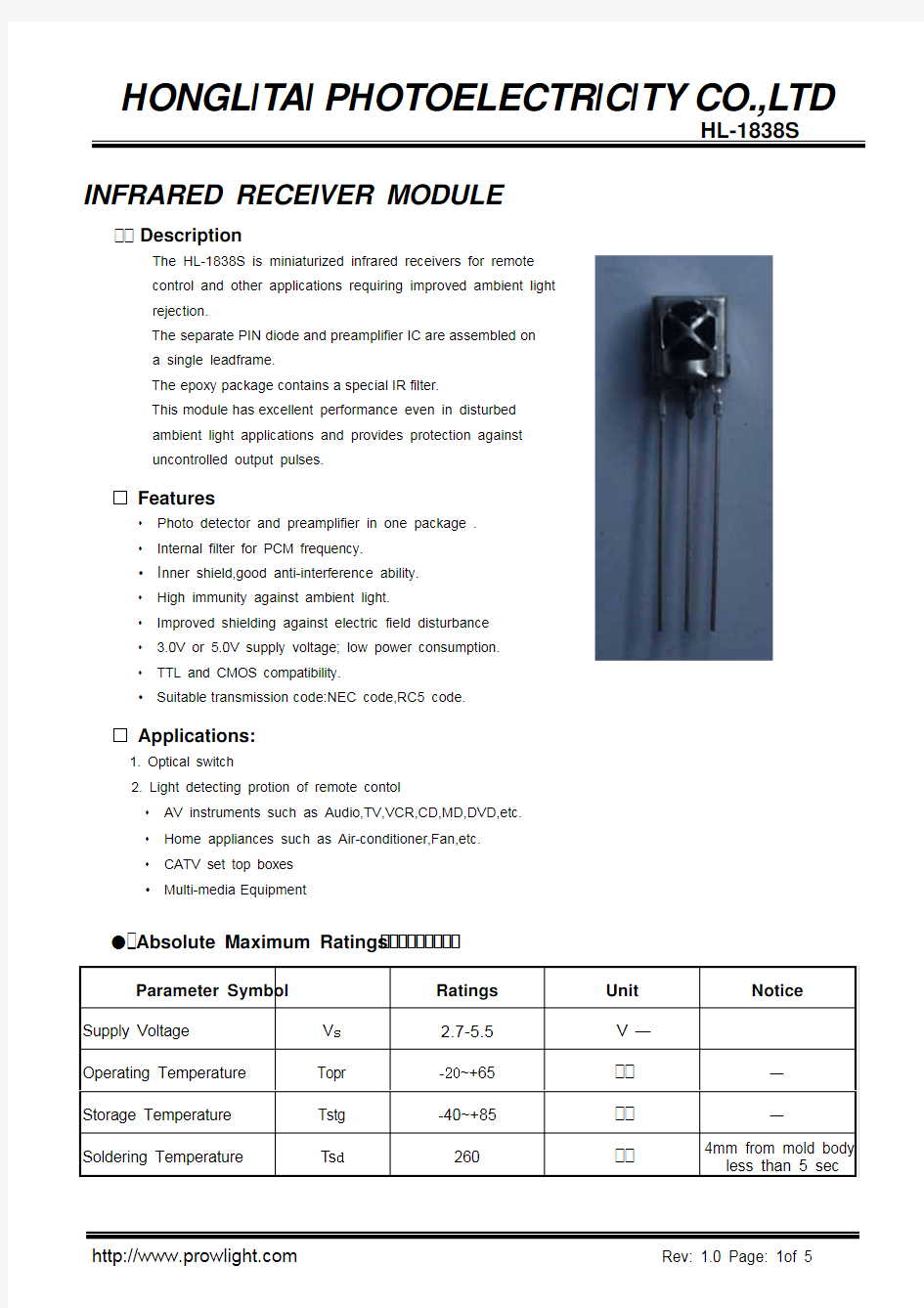
红外接收头

- 1、下载文档前请自行甄别文档内容的完整性,平台不提供额外的编辑、内容补充、找答案等附加服务。
- 2、"仅部分预览"的文档,不可在线预览部分如存在完整性等问题,可反馈申请退款(可完整预览的文档不适用该条件!)。
- 3、如文档侵犯您的权益,请联系客服反馈,我们会尽快为您处理(人工客服工作时间:9:00-18:30)。
INFRARED RECEIVER MODULE Description
The HL-1838S is miniaturized infrared receivers for remote
control and other applications requiring improved ambient light
rejection.
The separate PIN diode and preamplifier IC are assembled on
a single leadframe.
The epoxy package contains a special IR filter.
This module has excellent performance even in disturbed
ambient light applications and provides protection against
uncontrolled output pulses.
Features
• Photo detector and preamplifier in one package .
• Internal filter for PCM frequency.
• I nner shield,good anti-interference ability.
• High immunity against ambient light.
• Improved shielding against electric field disturbance
• 3.0V or 5.0V supply voltage; low power consumption.
• TTL and CMOS compatibility.
• Suitable transmission code:NEC code,RC5 code.
Applications:
1. Optical switch
2. Light detecting protion of remote contol
• AV instruments such as Audio,TV,VCR,CD,MD,DVD,etc.
• Home appliances such as Air-conditioner,Fan,etc.
• CATV set top boxes
• Multi-media Equipment
Absolute Maximum Ratings
Parameter Symbol Ratings
Unit Notice
Supply Voltage V s 2.7-5.5V — Operating Temperature Topr -20~+65 —
Storage Temperature Tstg -40~+85 —
Soldering Temperature Ts d260 4mm from mold body less than 5 sec
Electrical And Optical Characteristics
1:The ray receiving surface at a vertex and relation to the ray axis in the range of θ=0° and
θ=45°
2:A range from 30cm to the arrival distance. Average value of 50 pulses
BLOCK DIAGRAM
Ratings
Parameter Symbol
Min. Typ. Max.
Unit C ondition
Supply Voltage V s 2.7 - 5.5 V Supply Current
Icc
—
—
1.5
mA
No signal input
L 0 15 — —
Reception Distance
L 45 8 — — m
At the ray axis 1
B.P .F Center Frequency fo —
38
—
KHz
Peak Wavelength λp — 940 — nm
Half Angle
θ
— 45 — deg At the ray axis 1
High Level Pulse Width T H 400 — 800 µS
Low Level Pulse Width T L 400 — 800 µS At the ray axis 2
High Level Output Voltage V H 4.5 — — V Low Level Output Voltage
V L — — 0.5 V
Vcc GND
Test Method
B.Detection Length Test
A.Standard Transmitter Array 0V
Application Circuit
+5V Array
Infrared
Emitting
Diode
GND
Package Dimensions:
NOTES:
1.All dimensions are in millimeters (inches).
2.Tolerance is ±0.30mm (0.012’’) unless otherwise specified.
3.Specifications are subject to change without notice.
