西门子开关说明
西门子开关安装使用说明书2版
KYN28A-12(3AH5、3AH3)户内高压真空断路器安装使用说明书广东珠江开关有限公司二OO六年六月目录1概述1.1总则 (2)1.2使用条件 (2)1.3技术参数 (3)1.4机械参数 (3)1.53AH5外形尺寸 (4)1.63AH3外形尺寸 (5)2结构与功能2.1断路器总体结构 (6)2.2断路器内部接线原理图………………………………………….7~8 3调试和操作3.1准备工作 (9)3.2机构储能操作 (9)3.3合闸、分闸操作 (9)3.4与柜体配合过程操作 (9)4储运4.1运输 (9)4.2仓储 (10)5维修 (10)6随机文件 (10)7订货须知 (10).1概述1.1总则3AH5和3AH3户内高压真空断路器是三相交流50Hz,额定电压12kV 户内高压开关设备。
断路器符合IEC56、IEC694、BS531以及DINVDE0670的所有条款,而且还满足中国标准GB1984《交流高压断路器》和DL403(绝缘部分),并具有可靠的联锁功能。
重要说明:——主要零配件由西门子公司提供;——本公司是西门子公司授权制造商;——本公司与西门子公司进行技术合作,生产3AH开关;——产品受到西门子公司的质量监督和控制。
1.2使用条件1.2.1正常条件环境温度环境湿度最高温度+40℃日平均相对湿度95%≤最底温度-15℃月平均相对湿度90%≤日平均值不大于+35℃断路器装置地点的海拔高度最高可达1000m。
1.2.2特殊使用条件顾客若偏离正常使用条件可与制造厂家协商制造。
1.4机械参数——(表2)图1——正视图图3——正视图2结构与功能2.1断路器总体结构(图5)1.航空插座2.分闸按钮3.分合指示4.手柄储能孔5.合闸按钮6.储能指示7. 计数器8. 联锁装置9.绝缘子10.真空灭弧室11.导电触臂12.相间隔板13.绝缘挡板14.推进板15.底盘车16.框架2.2 断路器内部接线原理图(图6、图7)运行位置试验位置1~58 58针孔的航空插座 MO 弹簧机构的储能电机 K1 机构内部防跳继电器 Y1 分闸脱扣器 Y9 合闸脱扣器 S1 辅助开关 S21、S22、S3、S41 储能位置辅助开关 S8 试验位置辅助开关 S9 工作位置辅助开关图6——3AH5断路器内部接线原理图试验位置运行位置A1~D16 64针孔的航空插座 MO 弹簧机构的储能电机 K1 机构内部防跳继电器 Y1 分闸脱扣器 Y9 合闸脱扣器 S1 辅助开关 S21、S22、S3、S41 储能位置辅助开关S8 试验位置辅助开关 S9 工作位置辅助开关 Y0 闭锁电磁铁 S10 柜前合闸辅助开关 S11 柜体间联锁辅助开关图7——3AH3断路器内部接线原理图3调试和操作调试和操作中的各项工作应由受过专门训练、详细了解本装置开关设备性能的人员进行,工作中必须考虑相应的保护和预防措施。
西门子Vector系列集合操作开关说明书

Vector® seriesGroup-operated switches manual and motorized/disconnectswitchesOverviewDesigned for superior reliability and load-breaking performance, the Vector series of group-operated air-break switches includes 15/25 kV and 38 kV versions. Manufactured as a true unitized switch, the Vector series is completely factory assembled and adjusted to eliminate the need for tuning in the field. Utilizing Siemens innovative Saf-T-Gap interrupters for dependable loadinterruption, bolt-on style interrupters are supplied as standard with plug-in styleinterrupters available as an option for rapid change-out using a shotgun stick.VectorOperational reliability is enhanced byenclosing the operating mechanism inside the switch base for superior weather protection. Ease-of-operation is assisted with the use of environmentally sealed, oil impregnated sintered bronze bearings supporting a balanced-force operating mechanism. Galvanized steel, fiberglass, and aluminum tubular bases are available.2OverviewInstallation is made simple with the factory-installed “single-point lift bracket.” Provisions for dead-ending all three conductors is standard (on most models) along with the “pole hugger” design for improved aesthetics.All Vector series switches are available in pipe-operated versions, hookstick-operated gang versions and motorized versions with SCADA control.3Enclosed operating mechanismOperational reliability is assured by enclosing the operating mechanism inside the switch base to shield it from the environment. Two interposing rods balance the forces acting on the rotating insulator shafts to provide dependable push-pull switching.14123455DetailsHookstick-operated gangThe HOG – horizontalThe HOG – vertical* Weight does not include operating pipe.* Weight does not include operating pipe.6Pipe operatedDetailsPipe operated – horizontalPipe operated – vertical (cable riser style)* Weight does not include operating pipe.* Weight does not include operating pipe.7DetailsHookstick-operated gangThe HOG – symmetricalThe HOG – inverted* Weight does not include operating pipe.* Weight does not include operating pipe.* Weight does not include operating pipe.8Pipe operatedDetailsPipe operated – symmetricalPipe operated – inverted* Weight does not include operating pipe.* Weight does not include operating pipe.* Weight does not include operating pipe.9ConfigurationsThe Vector ® series is available in pipe-operated and hookstick-operated versions. For additional options or configurations, please contact yourSiemens representative.1410AutomationVersatility is key when it comes to operating a motorized group-operatedairbreak switch locally or remotely. Combining the field proven reliability of themanually operated Vector series with engineered controls, the Auto-Pak Vector(APV) enables applications such as auto-transfer and auto-sectionalizing.Optional voltage and current sensors can be mounted directly to the switch unitto provide a cost-effective line monitoring and fault detection solution.11Vector numbering systemPosition:12345*A B1C*Consult factory for custom configurations.12DetailsVector ratings:• 900/1,200 A continuous current• 630 A loadbreak• Momentarycurrent loadbreak• 25,000 A three second• 20,000 A one-time symmetricalfault close in• 15,000 A three-time symmetricalfault close in.Standard features:• Silver-to-silver hinge andjaw contacts• Dead-end bracket supplied asstandard (not available for verticalriser model)• E nclosed balanced bearingoperating mechanism• Pole-hugger operating shaft forimproved installation appearance• Four 7’ pipe sections, handle andlocking assembly and necessarycouplings and guides• Single-point lift bracket• All components packaged inone crate• 630 A bolt-on Saf-T-Gapinterrupters. Plug-in style availableas an option.• Copper-bronze live parts• Tinned terminal pads.3EK4 (APS) surge arrester3EK8 (APS) surge arrester131415Siemens Industry, Inc.99 Bolton Sullivan DriveHeber Springs, Arkansas 72543For more information, including service or parts,please contact our Customer Support Center.Phone: 1-800-333-7421/disconnectswitchesOrder No.: E50001-F630-A167-01-76USPrinted in U.S.A.© 2019 Siemens Industry, Inc.The technical data presented in this document is based on an actual case or on as designed parameters, and therefore should not be relied upon for any specific application and does not constitute a performance guarantee for any projects. Actual results are dependent on variable conditions. Accordingly, Siemens does not make representations, warranties, or assurances as to the accuracy, currency or completeness of the content contained herein. If requested, we will provide specific technical data or specifications with respect to any customer‘s particular applications. Our company is constantly involved in engineering and development. For that reason, we reserve the right to modify, at any time, the technology and product specifications contained herein.。
上海西门子开关 产品介绍 说明书

■ 上海西门子开关有限公司2的严格管理不仅贯穿于内部生产的各个流程,同时延伸至对供应商的日年在闵行经年底公司二期厂房扩建工程的竣平方米,体现了西门子根植于中国、长期服务于中国客户的信心和承诺。
2004年研发中心作为西门子输配电全球研发中心的组成部分,可同步共享西门子最新的技术和资源。
通过预测客户的需求,开发质量稳定可靠的创新型产品和为客户度身定制方案,使客户的业务增值。
一支反应迅速、装备精良、经验丰富的售后服务队伍和遍布全国的服务网点构成了公司一套高效的现场服务应对系统,负责指导产品现场安装和操作,并承诺在最短时间内对紧急情况作出应对,将客户的断电年位列上海市年被上海市电器行业协会评为行业名优产品。
公司因其良好的商业信誉被评为“守合同重信而被电气时代以及专3AH3及面向全球同步发售所有产品均在西安高压电器研究所通过型式试验,确保产品的运行安全和操作人员的人身安全。
目 录ContentsSiemens Switchgear Ltd., Shanghai (SSLS) is a joint venture of Siemens Ltd., China (SLC) and Shanghai Power Transmission & Distribution Company, holding the manufacturing license to apply the latest tech-nology of Siemens vacuum circuit-breaker and medium voltage switchgear in P. R. China.Since established in 1993, relying on Siemens powerful resources and internal boundless cooperation, SSLS has provided reliable products, first-class service and innovative solutions for more than two thousand key projects both for domestic and overseas. SSLS has established a good reputation and leading position in China due to its large contribu-tion to the technique innovation and development of local switchgear industry.SSLS is a market oriented company with commitment to customers’satisfaction and to fulfill the demands for the medium voltage switchgear, with high quality and excellent reliability, by means of dynamically intro-ducing and constantly developing the applicable technique and prod-ucts to the local market. Customer’s success is our first priority. We pledge to provide the most value-added product and service, promise on-time delivery, and establish solid business partner relationship with customers, in result to create the maximum value for our customers.SSLS began to implement the customer-oriented quality management early in1996, and established a comprehensive quality management system in 2004 integrated with ISO9001, ISO14001 and OHSAS18001. The company utilizes the highly sophisticated machines and testing fa-cilities in production process. The high qualification of operators along with continuous in process quality control guarantee our well established and high quality standards at all times. The strict quality control is not only carried out throughout entire production processes, but also ex-tended to the daily management of our suppliers. We take environment protection as our social responsibility; meanwhile closely look after employees’ occupational safety and health.To meet the growing marketing demands, a modern factory was built up in Minhang Economic & Technological Development Zone in 2004. With the completion of second phase expansion at the end of 2006, the land plot increased to 50000sqm and shop floor to 23000sqm, which em-bodies Siemens’ commitment to root in China and serve long-term for Chinese customers.According to company’s strategy to create more competence and shorter time-to-market, SSLS R&D center was established in 2004. R&D cen-ter closely integrates into the Siemens PTD global R&D network, could share the latest Siemens technique and resources in-phase. By pre-dicting the market needs, SSLS fosters R&D in developing reliable and innovative products and tailored solutions to add value for customer’s business.Siemens switchgear has an effective system of on-site servicing from a quick-respondent, well-equipped and rich experienced field service team and a network setup all over China. The team is responsible for the guidance of on-site installation and operational safety, commit to re-spond to emergency calls within the shortest possible time and to mini-mize down time.SSLS was ranged as the Top 500 Revenue of Industrial Companies in Shanghai 7 years in row since 2000. The products won the title of Shang-hai Reputed Product 4 years in row since 2003. The company was awarded as “Good Credit Enterprise” due to its high commercial credit, and won the title of “Top 10 Fast-growing Companies in China Electric Industry” in 2006 due to over 30% increase of sales revenue continu-ously over the past three years.PRODUCT INTRODUCTIONSSLS provides air insulated Switchgear rated from 7.2 to 24kV with type 8BK20, 8BK30, 8BK40 and specially designed for Chinese market in 2007 NXAIR S, and vacuum circuit breakers type 3AH3, 3AH5, 3AH2-EP as well as SION, the latest generation of Siemens VCB synchro-nously selling world wide.All products are type tested in XIHARI to ensure the safety of personnel and operation.公司简介Company Introduction■产品介绍3■ 上海西门子开关有限公司4● Draw-out section and access door fully inte-grated interlock system.● Safe and easy draw-out section movementbehind closed cubicle door.● Easy draw-out section transfer or exchange,using central service truck, independent of floor quality.● Earthed metal partitions and shutters.● Connection of HV cables is available from front or rear part of the panel optionally.● Back-to-back or face-to-face designs available for double bus-bar design.●Reinforced insulation which fulfills Chinese system and local climate.●Direct line-up with 8BK30 Vacuum ContactorSwitchgear.● 可移开部分与柜门之间有可靠的联锁● 前门关闭后,能够很安全而且容易地移动可移开部分● 先进的中置式结构,使用专门的小车能够方便地搬运或更换可移开部分,不受现场地面平整度的限制● 金属隔板与活门均接地● 根据用户需要,可由前门或开关柜的后部进行电缆接线● 开关柜可以面对面布置,也可以背靠背布置(双母线回路)●加强了绝缘,更适合中国电力系统和气候● 可直接与8BK30型开关柜(F - C 回路)联接供电典型客户上海供电局北京供电局兰溪电厂秦皇岛港口宁波小港纸业兰州石化TYPICAL CUSTOMER Shanghai PSBBeijing PSBLanxi Power PlantQinghuangdao HarborNingbo Xiaogang Paper MillLanzhou Petro 产品特点SPECIFIC FEATURES 电气技术数据 ELECTRICAL DATA (MAXIMUM VALUES )8BK20 Switchgear with Draw-Out Circuit-Breakers, Air-Insulated, Metal Clad8BK20型金属封闭/铠装可移开式空气绝缘断路器柜■ 产品介绍5● Draw-out section and door integrated in the inter-lock system.● Minimal space requirement.● Vacuum contactor and HVHRC fuses on draw-outsection. Vacuum contactor is able to operate fre-quently due to its long mechanic life-1 millionoperations.● Draw-out section easily to move inside the cubicle.● Cable connection in front of cubicle.● Directly line-up with circuit-breaker panel of type 8BK20.● Special wheels on bottom of draw-out section provide an easy movement during in and out the cubicle.● Reinforced insulation to meet Chinese system andlocal climate.● 可移开部分与室门之间装有可靠的联锁装置● 占用空间少● 可移开部分装有真空接触器和高压限流熔断器。
西门子ET200SP安全限位和安全开关说明书

/cs/ww/en/ps/16403/ae/et200sp /safety-relays /simatic-safetyDownloadhereFor the U.S. published bySiemens Industry Inc.100 Technology DriveAlpharetta, GA 30005,United StatesArticle No. SIEP-Y10286-00-7600© Siemens AG 2022All rights reserved.Subject to changes and errors.Mechanical position and safety switches Safety switches with separate actuator Non-contact safety switchesStandard/compact3SE51/3SE52/3SE543SF1 AS-i variantwithout tumbler3SE51/3SE523SF1 AS-i variantMagnet safety switches3SE66/3SE67Safety hinge3SE51/3SE523SF1 AS-i variantwith tumbler3SE533SF1 AS-i variantRFID safety switches3SE63RFID safety switcheswith tumbler 3SE64 DetectingSIRIUS Position and Safety SwitchesWith 2x switches(enabling individual switch combinations)Maximum safetySafety Integrity Level SIL (IEC 62061/IEC 61508)/Performance Level PL(ISO 13849-1)With 1x switchDesign typeTampering protection(Acc. to DIN EN ISO 14119, TÜV certificate)Positive opening operation asper IEC 60947-5-1, positive drive,necessary in safety applicationsEvaluatingApplication examplesWith the position and safety switches almostall requirements in the industrycan be met.Various application examples e.g. for guarddoor monitoring can be found here:SIL 3/PL e SIL 3/PL e SIL 3/PL e SIL 3/PL e SIL 3/PL e SIL 3/PL e SIL 3/PL e SIL 3/PL eMonitoring of1 NO contactMonitoring of1 NO contactMonitoring of1 NO contactMonitoring of1 NO contactMonitoring of 2 NOcontacts or 1 NOand 1 NC contactMonitoring of 2 NOcontacts or 1 NOand 1 NC contactMonitoring of 2 NOcontacts or 1 NOand 1 NC contactMonitoring of 2 NOcontacts or 1 NOand 1 NC contactMonitoring of 2 NO contactsor 1 NO and 1 NC contactSelf-monitoring with 2 electronic0SSD safety outputsSelf-monitoring with 2 electronic0SSD safety outputs SIL 1/PL c SIL 1/PL c SIL 1/PL c SIL 1/PL c SIL 3/PL e SIL 3/PL e SIL 3/PL eSIL 1/PL c SIL 2/PL d SIL 2/PL d SIL 2/PL d1122444low,actuator head uncodedlow,shaft uncodedlow,3D-coded actuatorlow,3D-coded actuatorlow,coded switching magnetlow or high (to choose),coded RFID security switcheslow or high (to choose),coded RFID security switchesPosition switch with twist lever:Detection of positions and end positionsof moving machine and system parts, suchas e.g. conveyor belts and assembly linesPivoting doors and flaps, with fixedpositive connection between switch anddoor hinge, switching angle 10°Roller door or position monitoringof grilles or doorsAdditional interlocking requirement, e.g.in the working area of a robot system:Shutdown of machines requires closedsafety doors with tumbler guardingMonitoring of maintenance flaps(hoods, doors, grilles), especially suitablefor confined spacesMonitoring of swing doors, flaps, hoods,grilles, vibration-proof and robust IP69,large switching intervalInterlocking requirement for rotating,laterally movable or removable safetyguards IP69, with latching, optimizedhygiene standard with simultaneoushighest personnel andprocess protectionSIMATIC ET 200SP SIRIUS 3SK safety relays SIMATIC controller Application manualSIRIUS Safety Integrated1.) Without tumbler2.) W ith lockingdevicePublished bySiemens AGSmart InfrastructureElectrical ProductsWerner-von-Siemens-Str. 48-5092224 AmbergGermany。
西门子 6300A 系列高压开关柜 运行维护手册说明书

一、 高压开关柜概述1.基本概念a)开关柜(又称成套开关或成套配电装置):它是以断路器为主的电气设备;是指生产厂家根据电气一次主接线图的要求,将有关的高低压电器(包括控制电器、保护电器、测量电器)以及母线、载流导体、绝缘子等装配在封闭的或敞开的金属柜体内,作为电力系统中接受和分配电能的装置。
b)高压开关设备:主要用于发电、输电、配电和电能转换的高压开关以及和控制、测量、保护装置、电气联结(母线)、外壳、支持件等组成的总称。
c)开关柜防护要求中的“五防”:防止误分误合断路器、防止带电分合隔离开关、防止带电合接地开关、防止带接地分合断路器、防止误入带电间隔。
d)母排位置相序对应关系:表1相别颜色母线安装相互位置垂直水平引下线A相黄上远左B相绿中中中C相红下近右e)防护等级:外壳、隔板及其他部分防止人体接近带电部分和触及运动部件以及防止外部物体侵入内部设备的保护程度。
表2防护等级简称定义IP1X防止直径大于50mm的物体1.防止直径大于50mm的固体进入壳内;2.防止人体某一大面积部分(如手)意外触及壳内带电部分或运动部件IP2X防止直径大于12.5mm的物体1.防止直径大于12.5mm的固体进入壳内;2.防止手触及壳内带电部分或运动部件IP3X防止直径大于2.5mm的物体1.防止直径大于2.5mm的固体进入壳内;2.防止厚度(直径)大于2.5mm工具或金属线触及柜内带电部分或运动部件IP4X防止直径大于1mm的物体1.防止直径大于1mm的固体进入壳内;2.防止厚度(直径)大于1mm工具或金属线触及柜内带电部分或运动部件IP5X 防尘1.能防止灰尘进入达到影响产品的程度;2.完全防止触及柜内带电部分或运动部件IP6X 尘密1.完全防止灰尘进入壳内;2.完全防止触及柜内带电部分或运动部件2.开关柜的主要特点:a)有一、二次方案,这是开关柜具体的功能标志,包括电能汇集、分配、计量和保护功能电气线路。
一个开关柜有一个确定的主回路(一次回路)方案和一个辅助回路(二次回路)方案,当一个开关柜的主方案不能实现时可以用几个单元方案来组合而成。
西门子高压电源开关设备产品介绍说明书

Siemens GBS PortfolioMedium Voltage & SystemsRestricted © Siemens AG 2017/generatorswitchgearA Tale of Two Technologies For MV Generator Breaker SwitchgearSF6 VacuumVacuum Technology – Success Story Overview of the global market share of MV Circuit Breakers Market Penetration of vacuum breakers for MV•In 1980 – 20%•Nowadays – around 80%Reasons for success•High number of operation cycles•Preservation of the quality of the vacuumthroughout the entire life time•No monitoring system required •Maintenance-free •Environmentally friendly •Compact construction194656 6165 7075 8071520222220202036282417 1310 50%10%20%30%40%50%60%70%80%90%100%19801985199019952000200520102015 MarketShareforMVCircuitBreakersVacuum SF6Magnetic Min. Oil Bulk OilAdvantages of Vacuum Interruption over GasVacuum Interrupters are sealed for life•Breaking capability not affected by pressure and temperature of gas• No maintenance and monitoring of contact system• No capacitor required for High short circuit applications• No low ambient temperature concernsSpring-Spring Drive Mechanism•Opening time and speed are not affected by pressure andtemperature of hydraulic oil• No blocking of trip on low gas/hydraulic pressureNumber of Operations:• 10,000 operation electrical and mechanical cycles at rated current• 30 interruptions at 100% of short circuit current• 300 interruptions at 10-100% of short circuit currentSiemens TechnologyComparison of Lifecycle CostsLifecycleC o s t sMinimum operational andmaintenance costsG C BVacuumSignificantly lower lifecycle costGCBPurchase priceHigher number of switching operationsBreaking current [kA]O p e r a t i n g c y c l e sInstallation costSF61101001000100001000000.1110100Vacuum GCB -100kA (*)SF6 GCB -100kA (**)(*) SF6 GCB according to manualHECS – 100L document no. 1HC0066312 AC D01 Up to 70% reduction in lifecycle costsGenerator Circuit-Breaker Switchgear PortfolioHB1 - Horizontal BusbarRemovable type up to 170 MW up to 24 kV up to 6,700 A up to 72 kA, 1 sHB3 - Horizontal BusbarRemovable type up to 400 MW up to 24 kV up to 12,500 A up to 100 kA, 3 sVB1 – Vertical busbarRemovable type up to 140 MW up to 24 kV up to 5,500 A up to 72 kA, 1 sVB1-D – Vertical busbar, DrawableWithdrawable type up to 110 MW up to 17.5 kV up to 5,100 A up to 63 kA, 3 sGM-SGWithdrawable type, ANSI up to 80 MW up to 15 kV up to 4,000 A up to 63 kA, 3 sNXAIRWithdrawable type, IECup to 50 MW up to 17.5 kV up to 4,000 A up to 50 kA, 3 sGenerator Circuit-Breaker Switchgear GM-SG – Technical Data Application:Practical range 10 - 80 MW GeneratorsRatings:•U r:15 kV•I r:up to 3,000 A (4,000 A - forced cooling) •I sc (3 s):up to 63 k ABreaker types:•Type tested to IEEE C37.013a•Arc Resistant - Type 2B Dimensions:•914 x 2,507 x 2,419 mm (W x D x H) Installation•Indoor or outdoor application Connection methods •Cable•Bus ductsDegree of protection NEMA1 / NEMA3RRetrofit SolutionsMedium Voltage & SystemsRestricted © Siemens AG 2017/generatorswitchgearContact InformationDanish Mirza BaigBusiness Developer,Energy Management, Medium VoltageCalgary, ABMobile: +1 (403) 607-7617E-mail: ***********************siemens.ca/energymanagementSiemens Canada 2018Seite 50 /generatorswitchgear。
西门子8dh开关说明书
• 100% switchgear interlocking by means of logical mechanical interlocking
• Mechanical switch position indications are integrated in the mimic diagram
Switchgear up to 24 kV, SF6-Insulated, Extendable, Type 8DH10
Typical design
Technical features
• Maintenance-free
• Independent of climate
• Three-pole primary enclosure, metal-enclosed, metal-clad
Economic considerations
Extremely low life-cycle costs and extremely high availability throughout the entire product service life as a result of:
• Maintenance-free concept
• Up to 24 kV
• Feeder currents up to 630 A
• Busbar currents up to 1250 A
Typical uses
8DH10 switchgear is used – even under severe environmental conditions – for power distribution in secondary distribution systems, e.g. in
西门子开关安装使用说明书

KYN28A-12(3AH5、3AH3)户内高压真空断路器安装使用说明书广东珠江开关有限公司二OO六年六月目录1概述1.1总则 (2)1.2使用条件 (2)1.3技术参数 (3)1.4机械参数 (3)1.53AH5外形尺寸 (4)1.63AH3外形尺寸 (5)2结构与功能2.1断路器总体结构 (6)2.2断路器内部接线原理图…………………………….7~8 3调试和操作3.1准备工作 (9)3.2机构储能操作 (9)3.3合闸、分闸 (9)3.4与柜体配合过程操作 (10)4储运4.1运输 (10)4.2仓储 (10)5维修 (10)6随机文件 (10)7订货须知 (11)1概述1.1总则3AH5和3AH3户内高压真空断路器是三相交流50Hz,额定电压12kV户内高压开关设备。
断路器符合IEC56、IEC694、BS531以及DINVDE0670的所有条款,而且还满足中国标准GB1984《交流高压断路器》和DL403(绝缘部分),并具有可靠的联锁功能。
重要说明:——主要零配件由西门子公司提供;——本公司是西门子公司授权制造商;——本公司与西门子公司进行技术合作,生产3AH开关;——产品受到西门子公司的质量监督和控制。
1.2使用条件1.2.1正常条件环境温度环境湿度最高温度+40℃日平均相对湿度95%≤最底温度-15℃月平均相对湿度90%≤日平均值不大于+35℃断路器装置地点的海拔高度最高可达1000m。
1.2.2特殊使用条件顾客若偏离正常使用条件可与制造厂家协商制造1.3技术参数——(表1)1.4机械参数——(表2)正视图——(图1)正视图——(图3)2结构与功能2.1断路器总体结构——(图5)1.航空插座2.分闸按钮3.分合指示4.手柄储能孔5.合闸按钮6.储能指示7. 计数器8. 联锁装置9.绝缘子10.真空灭弧室11.导电触臂12.相间隔板2.2 断路器内部接线原理图运行位置试验位置1~58 58针孔的航空插座 MO 弹簧机构的储能电机 K1 机构内部防跳继电器 Y1 分闸脱扣器 Y9 合闸脱扣器 S1 辅助开关 S21、S22、S3、S41 储能位置辅助开关 S8 试验位置辅助开关 S9 工作位置辅助开关3AH5断路器内部接线原理图——(图6)试验位置运行位置A1~D16 64针孔的航空插座 MO 弹簧机构的储能电机 K1 机构内部防跳继电器 Y1 分闸脱扣器 Y9 合闸脱扣器 S1 辅助开关 S21、S22、S3、S41 储能位置辅助开关S8 试验位置辅助开关 S9 工作位置辅助开关 Y0 闭锁电磁铁 S10 柜前合闸辅助开关 S11 柜体间联锁辅助开关3AH3断路器内部接线原理图——(图7)3调试和操作调试和操作中的各项工作应由受过专门训练、详细了解本装置开关设备性能的人员进行,工作中必须考虑相应的保护和预防措施。
西门子NXAirS 550+ 空气耐用中压电路器开关系统说明书

Scan QRcode to knowmore aboutNXAirS 550+CatalogHA 1797Edition 2019/nxairsBuildingsInfrastructureData centerMarine / Harbor 2Air-insulated Compact Medium-Voltage Switchgear NXAirS 550+ CatalogFeatures and ApplicationsSiemens medium-voltage air-insulated switchgearThe air-insulated switchgear follows the classic de-sign of NXAirS and has the features of NXAirS stand-ard switchgear. Its width is optimized to be 550mm, so as to provide more compact solution for the increasingly scarce space and reduce the construc-tion investment expenses due to the reduced space requirement.Siemens NXAirS air-insulated switchgear comprises busbar, switching device, connection, low-voltage compartment. The switchgear’s frame and compart-ments are metallic enclosed. Shutters and partitions are earthed. Each compartment is metal-clad in pressure resistant design to increase the operator’s safety.FeaturesAir is available as an insulating medium and free from special treatment. It has no leakage risk and monitoring demand.Siemens 3AE vacuum circuit-breakers are mainte-nance-free within 10,000 times and reach mechan-ical operations up to 30,000 times. The mainte-nance-free circuit-breakers and the modular design enable continuous operation without expensive shutdown time. The modular design will also makes the installation easier.All switchgear types of NXAirS 550 + passed with internal arc classification IAC A FLR, loss of service continuity category LSC2B and partition class PM. All these helps to meet the highest requirments, regard-ing personal safety.Typical ApplicationsNXAirS 550 + air-insulated switchgear is widely applied in the fields which have high requirements for low space-consuming installations, such as data center, marine and harbor, buildings, etc. Its flexible combination with Siemens classical NXAirS Series switchgear can better meet your increasing demands of diversified switchgear typicals and expansibility.Classification DescriptionNXAirS 550+switchgear meet the requirements of IEC 62271-200 and GB 390634Air-insulated Compact Medium-Voltage Switchgear NXAirS 550+ CatalogTechnical parameters for NXAirS 550+air-insulated switchgear (up to)Technical parameters of vacuum circuit-breaker (up to)Electrical DataAir-insulated Compact Medium-Voltage Switchgear NXAirS 550+ CatalogCircuit-breaker Panel5Air-insulated Compact Medium-Voltage Switchgear NXAirS 550+ Catalog Circuit-breaker Panel6Air-insulated Compact Medium-Voltage Switchgear NXAirS 550+ Catalog Disconnecting Panel7Air-insulated Compact Medium-Voltage Switchgear NXAirS 550+ Catalog Disconnecting Panel8Air-insulated Compact Medium-Voltage Switchgear NXAirS 550+ CatalogBus Sectionalizer9Air-insulated Compact Medium-Voltage Switchgear NXAirS 550+ Catalog Bus Sectionalizer10Air-insulated Compact Medium-Voltage Switchgear NXAirS 550+ Catalog Voltage Transformer Panel11Air-insulated Compact Medium-Voltage Switchgear NXAirS 550+ Catalog Metering Panel1213Air-insulated Compact Medium-Voltage Switchgear NXAirS 550+CatalogSelf-used Transformer Panel / Symbol Description Self-used Transformer Panel* VPIS: Voltage Presence Indicating System14Air-insulated Compact Medium-Voltage Switchgear NXAirS 550+ CatalogFeatures• Integrated mimic diagram.• Display of the respective switch positions for circuit-breaker CLOSED/OPEN, disconnected po-sition, earthing switch CLOSED/OPEN, on the integrated mimic diagram.• Unambiguous assignment of actuating openings and control elements to the corresponding position indicators.• All switching operations are always with high-voltage door closed.• Ergonomically favorable height for all control and indicator ele-ments.• Options: Verification of safe iso-lation from supply for feeder or busbar by means of the capac-itive voltage detecting system with panel front closed.Interlocks• Interlock conditions specified according to IEC 62271-200/GB3906 are fulfilled.• Earthing switch can only be operated with switching device in disconnected position.• Switching device can only be racked on the movable part with the assocaited switching device OPEN position and with earthing switch OPEN.Option: Electromagnetic interlock, mechanical key interlocking systemBasic Design of SwitchgearSwitchgear Structure (as illustrated)15Air-insulated Compact Medium-Voltage Switchgear NXAirS 550+ CatalogSwitchgear Design IntroductionNXAirS 550+ air-insulated compact switchgearThe frame is made of high-strength corrosion-resist-ant AI-Zn-plated steel plate and we take its design of safety and convenient installation into considera-tion. Each switchgear comprises a switching device, a busbar compartment, a connection compartment and a low-voltage compartment. Each compartment provides a pressure relief channel whose metallic lid can be opened automatically. If internal arcing fault occurs, the channel can release arcing pressure im-mediately, which can guarantee operators’ personalsafety.Switching Device Compartment- Shutter mechanism in the switching device compartment is such arranged to easily open and close the busbar compartment and connection compartment. It can be opened and closed automatically with the moving of switching device.- It is equipped with metal cable wireway on the left, which used for paving control line so as to take effective use of the space in the cabinet. In this way, we make the internal compartment neater and metallic cover the LV wires .- Depending on the typical, it is possible to arrange vacuum circuit-breaker, disconnecting or metering unit.Low-voltage plug connector for connection of control cables between primary part and secondary part. Only when at the test position, can the circuit-breaker be plugged into or out of secondary plug. The interlock is installed between the secondary plug and circuit-breaker. It can ensure the high-voltage door closed only when the plug is well-plugged.Low-voltage Compartment- Low-voltage compartment can be customized according to customers' requirements and is internally equipped with various protection, control, measurement and metering equipment.- Low-voltage compartment is 705mm high. and it can achieve the height of max. 980mm according to the requirements.- Low-voltage compartment is arranged such to be ergonomic, suitable in height and convenient for operation and observation.- Lines are encoded by laser printing. They can be arranged appropriately and the encoded ones are convenient for on-site checking.Low-voltage compartment with built-in equipment (only example)16Air-insulated Compact Medium-Voltage Switchgear NXAirS 550+ CatalogCompartment introductionBusbar compartment- Enclosure made of Al-Zn-plated sheet steel.- Pressure relief upwards.- Busbar adopts conventional "top and twin-side bottom" structure of NXAirS switchgearto save the vertical space. The same structure and position of the busbar enables easycombine with other different NXAirS series panel.- Siemens use flat copper, bolted from panel to panel. The bolt hole is rhombic designand convenient for construction personnel's site installation .Connection Compartments- Enclosure made of Al-Zn-plated sheet steel.- Pressure relief upwards through rear pressure relief duct.- The connection compartment, with large space therein, can connect multiple cables;the cable connection height is high enough to make the installation easier.- We can provide both cable-in options from the bottom and the top as customersrequirement.- According to customer requirements, components like CT, PT and make-proof earthingswitch can be installed.- We recommend LZZBJ9-12/150b/2 as CT, JDZXR-10X (3PTs) as PT or JSZVR2-10C1(2PTs).17Air-insulated Compact Medium-Voltage Switchgear NXAirS 550+ CatalogSwitchgear Components Introduction3AE Vacuum Circuit-breaker- Siemens has more than 30-year-experience of vacuum products design and operating.- It is maintenance-free for more than 10000 times and reaches a mechanical life up to 30,000 times under normal conditions with maintennance.- The contact of vacuum interrupt adopts Cu-Cr alloy and has high dielectric strength, high short-circuit breaking, strong arc erosion resistance capability and very low contact resistance.- Highly flame-retardant insulating materials are used and all organic material parts meet the requirements for Grade V0 self arc extinguishing stipulated according to UL standard.SIPROTEC 4 SeriesSIPROTEC 4 7SJ62 multifunction protection relayIt is a microcomputer integrated protection measuring and control device, which provides a human machine interface. Its parameter can be input via panel keyboard in order to facilitate the practical operation.- Overcurrent and zero sequence overcurrent protection with or without directions - Under frequency and over frequency protection - Under voltage and over voltage protection - Reclosure function- Programmable CFC function- IEC 60870-5-103, Modbus or IEC 61850 communication protocol (GOOSE message) - Two optional ports: RS485 port and Ethernet port- Front USB port: convenient for remote maintenance and fault diagnosis More models will be provided for various demands18Air-insulated Compact Medium-Voltage Switchgear NXAirS 550+Catalog① Cable Position ( Depends on whether cableis used or not)② Control Cable Position③ Fixed Point, 20×60mm rectangular hole ④ Install 5# U-bar in front and rear of theswitchgearA Standard panel1350B Panel with busbar riser in busbar compartment 1480CPanel with standard rear duct 460 mm1810Foundation DimensionABCT: Panel Depth (mm)19Air-insulated Compact Medium-Voltage Switchgear NXAirS 550+ CatalogApplicable Standards and Applicable EnvironmentApplicable StandardsSwitchgears comply with corre-sponding standards and specifi-cations.Applicable Environment1. A mbient air temperature: -15℃ ~ +40℃;2. R elative humidity: daily mean ≤95%; monthly mean ≤90%.3. A ltitude: ≤1,000m;4. S eismic intensity: ≤VIII;5. E nvironment without fire hazard, explosion hazard or severe contamination, chemical corrosion and violent vibration.Where applicable environment exceeds above-mentioned range, users need negotiate with Siemens for permissible range and technical measures.For site altitudes above 1000 m, the altitude correction factor Ka is recommended, depending on the site altitude above sea level.Rated short-duration power-frequency withstand voltage to be selected for site altitudes > 1000 m≥ Rated short-duration power-frequency withstand voltage up to ≤ 1000 m · Ka Rated lightning impulse withstand voltage to be selected for site altitudes > 1000 m ≥ Rated lightning impulse withstand voltage up to ≤ 1000 m · KaExample:2000 m site altitude above sea level, 12 kV switchgear rated voltage,75 kV rated lightning impulse withstand voltage,Rated lightning impulse withstand voltage to be selected =75 kV*1.14=85.5 kV Result:According to the above table, a switchgear for a rated voltage 12kV with a rated lighting impulse withstand voltage of 86kV is to be selected.Altitude correction factor K aStandard OverviewSite altitude in m above sea level10001.001.101.201.301.40Am = 1H A 40-2037b e n e p sa150020002500300035004000A l t i t u d e c o r r e c t i o n f a c t o rPublished bySiemens Ltd., ChinaSiemens AGSmart InfrastructureDistribution SystemsMozartstraße 31 C91052 ErlangenGermanySiemens Ltd., ChinaSmart InfrastructureDistribution Systems299, Tianning Road, Min Hang District200245 SHANGHAI, ChinaSiemens Switchgear Limited Shanghai298, Tianning Road, Min Hang District200245 SHANGHAI, ChinaFor further information please contactOur Customer Support CenterPhone: +49 180 524 7000Fax: +49 180 524 2471Order No.: E MMS-B80049-00-5DCN1797-S906573-0719.5Subject to changes and errors. The information given in this document only contains general descriptions and/or performance features which may not always specifically reflect those described, or which may undergo modification in the course of further development of the products. The requested performance features are binding only when they are expressly agreed upon in the concluded contract.NXAirS and SION are registered trademarks of Siemens AG. Any unauthorized use is prohibited. All other desginations in this document may represent trademarks whose use by third parties for their own purposes may violated theproprietary rights of the owner.。
西门子开关3AP1-FG介绍

断路器控制回路电源采用直流220V,220kV液压机构储能电动机电源采用交流380V(三相),110kV及35kV弹簧储能电动机电源采用交流220V(单相)。
发变线路组使用SF6开关,由一台弹簧操作机构进行三极机械联动,SF6开关内SF6气体额定压力为0.6Mpa(20℃)。
开关具有一个合闸线圈和两个跳闸线圈,当开关处于“合闸”状态时在操作机构中机械合闸闭锁生效,避免操作机构的再次合闸。
当SF6气体压力降至0.52Mpa(20℃)发出“SF6泄漏”信号,随后开关必须分闸,并及时通知检修补充合格的SF6气体恢复至额定气压。
补气时开关必须被隔离,补气结束之后,开关可以重新投入运行。
如果一段时间之后上述信号再次出现,应测出泄漏的位置,采取措施加以密封。
如无法密封,应及时通知厂家。
当SF6气体压力继续下降至0.5Mpa(20℃),SF6总闭锁1(接触器K10常开接点返回)闭锁开关跳合闸(SF6气体年漏气量≤1%),并在DCS开关操作器“合闸条件”中显示不允许;SF6总闭锁2(接触器K55常开接点返回)发“SF6总闭锁”报警信号。
断路器型号含义:3AP1-FG:3A---西门子开关; P---60ms开断; 1---单断口; F---弹簧机构; G---三相操作一、开关的巡视检查项目1.SF6气体压力随温度变化曲线见说明书,20℃正常气体压力6.0bar。
2.开关各部分及管道无异声(漏气声、振动声)及异味,管道夹头正常。
管道无裂痕,无放电声和电晕。
3.引线连接部位无过热,引线驰度适中。
4.开关本体瓷瓶清洁,无裂纹、破损。
5.开关分合位置指示正确,弹簧机构储能正常,并和当时实际运行情况相符。
6.开关防爆膜应完好无损。
7.接地完好。
8.巡视环境条件良好,附近无杂物。
二、弹簧机构巡视检查项目1.开关端子箱储能电源闸刀、熔丝状态正常。
2.机构箱门平整,开启灵活,关闭紧密。
3.储能电动机行程开关接点无卡住和变形,启动正常,无异声、异味。
西门子开关PT柜电压继电器说明书MRU3_2_cn
4 工作原理 4.1 模拟回路 4.2 数字回路 4.3 星形或三角形接线法选择 4.4 电压监视 4.4.1 单相/三相监视 4.4.2 电压不平衡保护原理 4.4.3 测量原理 4.4.4 对称电压系统的负序系统 4.4.5 电压不平衡系统 4.4.6 零序系统 5 操作和整定 5.1 显示 5.2 整定步骤 5.3 系统参数 5.3.1 一次量(Uprim/Usec)显示剩余电压 UE 5.3.2 D/Y – 转换 5.3.3 额定电压的设置 5.3.4 激活储存的显示 5.3.5 参数组转换开关/故障记录仪的外部触 发器 5.4 保护参数 5.4.1 单相或三相 U</U>-跳闸 5.4.2 过压和欠压监视的参数整定 5.4.3 正序系统电压 (U1<, U1>) 5.4.4 负序系统过压 (U2>) 5.4.5 零序系统过压 (U0>) 5.4.6 从属地址的调节 5.4.7 波特率的整定 (仅适用于 Modbus协议) 5.4.8 奇偶校验的整定 (仅适用于 Modbus协议) 5.5 故障记录仪参数 5.5.1 故障记录仪的调节
或
闭锁可通过配置模式自由选择(参阅第5.9节)。 输入端 D8 是闭锁与外部复位的接地(L- 或 N)。闭锁 功能在辅助电压从 D8/E8 端子断开后立即恢复。 以上功能在施加电源电压后闭合 2 秒钟。 3.1.3 外部复位输入 独立于记录时间,整个储存空间可被分成数个干扰 事件,每个带较短的记录时间。此外,故障记录仪 的清除功能也会受影响。 不可覆盖 如选择 2、4 或 8 个记录存储,整个储存空间就会 分成相应数量的储存块。当超过故障事件的最大记 录数量时,故障记录仪会阻止更多的记录,防止已 存数据被覆盖。在读取或删除数据后,记录仪将继 续记录。 的 采样 频 率是 1.25 ms ( 50 Hz) 和 1.041 ms ( 60 Hz),并被储存在循环缓冲器内。 存储分区
西门子开关说明

西门子开关(3AQ1 EE)说明一、技术数据:1、3AQ1 EE型开关是一种采用SF6气体作为绝缘和灭弧介质的压气式高压开关,三相设计户外式。
灭弧所需的灭弧介质压力在分闸过程中通过灭弧单元中的一个压气活塞设备形成。
开关的每个相装有一液压操作机构,以使开关适用于单相的和三相的自动重合闸。
2、本开关适用的环境温度范围为:-25℃至+50℃。
3、符合IEC标准的绝缘水平:额定电压:252kV额定工频耐压在50Hz时对地:460kV 断口间:460kV 相间:460kV最大额定雷电冲击电压(1.2/50μs)对地:1050kVmax 断口间:1050kVmax相间:1050kVmax绝缘距离对地:2×1100mm 断口间:1900mm 相间:3055/2455mm最小爬距:对地大-小-绝缘子裙:6300mm断口间大-小-绝缘子裙:7595mm4、电气数据:额定电压:252kV额定频率:50Hz额定电流:3150/4000A额定短路开断电流:50kA额定关合电流:2.5×额定短路开断电流额定短路持续时间:3s额定操作程序:O-0.3s―CO―3min―CO5、开关动作时间:指令最小持续时间:50ms合闸时间:105±5ms分闸时间:36±3ms燃弧时间:max21ms开断时间:max60ms合-分-时间:58±12ms间隔时间:300ms6、液压压力监视:动作值安全阀:375/37.5bar/MpaN2泄漏:355/35.5 bar/Mpa液压泵“合”:320/32.0 bar/Mpa自动重合闸闭锁:308/30.8 bar/Mpa合闸闭锁:273/27.3 bar/Mpa总闭锁:253/25.3 bar/Mpa7、灭弧介质SF6:额定电压:252kV每台开关的充气量:20kg每台开关的充气体积:335dm320℃时的额定压力:7.0/0.7 bar/MpaSF6监控20℃时“SF6泄漏”信号:6.4/0.64 bar/Mpa20℃时总闭锁:0.2/0.02 bar/Mpa在“SF6泄漏”信号以下机械开断时SF6的最小压力:3.0/0.3 bar/Mpa每个极柱的过滤材料:4.5kg8、液压操作机构:液压储能筒的容量:14dm3油量(整台开关):25 kg20℃时N2的预充压力:200-5/20-0.5 bar/Mpa压力范围:250···375/25.0···37.5 bar/Mpa储存的操作程序:CO-15s-COO-0.3S―CO―3min―CO油泵:300bar时的供油量:0.9 dm3/min直流电源0.7 dm3/min交流电源额定电压:208/120 220/127 230/133 380/220 400/230 415/240 440/254 480/280 操作箱:45W液压操作机构:2×15W11、辅助开关:型号:3SV 92额定电压:250V DC持续电流:10A可自由支配的触头:4NC,4NO,2滑动触头开断容量:电阻性负载常闭触头和常开触头:2.5A滑动触头:2.5A电阻电感性负载:2A时间常数τ:20ms二、开关构造:1)开关基架2)控制箱3)液压储能筒4)液压操作缸5)绝缘子6)灭弧室三个开关相安装在同一个开关基架上,此开关基架作为底架或支架组成底座构造。
西门子智能基础设施集团差压开关QBM81说明书
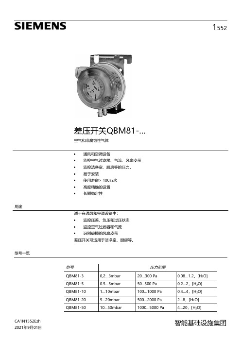
1552差压开关QBM81-…空气和非腐蚀性气体•通风和空调设备•监控空气过滤器、气流、风扇皮带•监控洁净室、厨房等的压力。
•易于安装•使用寿命> 100万次•高度精确的设置•长期稳定性用途适于在通风和空调设备中:•监控压差、负压和过压状态•监控空气过滤器和气流•识别破损的风扇皮带差压开关可适用于洁净室、厨房等。
型号一览2/6 订购信息订购时,请注明数量、名称和产品编号。
示例: 1个差压开关QBM81-5附件风管传感器FK-PZ3包含在交付产品中。
其他附件必须单独订购。
机械设计差压开关QBM81-...包括:• 外壳和盖子 • 膜片• 1 X 钢板安装支架附件-风管传感器连接套件(FK-PZ3):• 2 X 风管接头 • 4 X 固定螺钉• 2 m 管道,直径5/8 mm附件为了精确测量,必须交付两个附加的风管传感器组;另请参见数据表CA1N1589E : FK-PZ1 套件包含两个带橡胶垫圈的不锈钢风管接头 FK-PZ2 套件包含两个带铝制固定插座的风管接头,4个螺钉技术设计两个压力接头之间的压差使弹簧膜片偏转。
这种特殊的膜片可保证开关点的长期稳定性。
每种型号都刻有单独的刻度,可进行非常精确的调节。
调节选项参见下列“功能”部分5个图表中的图示说明。
功能 功能图X D =开关差 △p=压差 W =开关点,顶部开关点 开关状态3/6开关点,顶部[P a ]开关差[Pa]开关差[Pa]开关差[Pa]开关差[Pa]开关差[Pa]1)出厂设置应用示例过滤器监控 流量监控+ 过滤器上游压力 + 风扇下游压力–过滤器下游压力– 进口侧风扇上游压力,或大气压力。
径向风扇,位于入口中心。
安装注意事项开关点,顶部[P a ]开关点,顶部[P a ]开关点,顶部[P a ]开关点,顶部[P a ]开关点,顶部[P a ]差压开关中随附安装说明。
压力开关适合安装在风管或墙壁上。
建议垂直定向安装,但原则上任何定向均可。
西门子断路器说明书

真空断路器 3AH3 7.2KV-36KV(2)真空灭弧室图2/5给出了用于3AH3真空断路器中的真空灭弧室的基本结构的剖视图。
根据型号,真空灭弧室(30.)被固定在上支架(20.)。
电弧室(33.)安装在两个陶瓷绝缘子(32.)之间。
静触片(31.)被直接连接在柜上。
动触片(36.)被安装固定在导轨(35.)中的接线端子螺栓(36.1)上。
金属波纹管形成到灭弧室的真空密封连接。
图2/5真空灭弧室安装在3AH3真空断路器中的真空灭弧室被定型核准符合联邦德国的X 射线规则。
它们符合1987年1月8号(联邦法公报第144页)§8规定的X 射线规则的要求和附件Ⅲ第5部分规定的额定瞬间交流电压符合DIN VDE/IDE 标准。
补充说明基本型号的真空断路器包括:带有机械和电气反转的电气操作机械(储能电动机)(M1)合闸线圈(Y9)脱扣分路(Y1)64头带金属孔眼套筒的低压插塞式连接器(X0)辅助开关,6常开+6常闭(S1)“合闸线圈储能”信号的位置开关(S41,S42)断路器分闸信号,信号复位开关(S6,S7)操作次数计数器防止误合闸的闭锁每个3AH3真空断路器也可以装有下面一些设备:接线板(X0)扩展的辅助开关,12常开+12常闭(S1)脱扣分路3AX1101 (Y2)电流互感器操作脱扣3AX1102 (Y4,Y5)电流互感器操作脱扣3AX1104(0.1WS)(Y6)低电压脱扣3AX1103 (Y7)手动电气合闸机械闭锁除标准的脱扣分路外,3AH3真空断路器也可以最多安装两个3AX11型脱扣分路。
在一览表HG11中声明了容许的辅助设备组合和特定的型号。
安装在配电柜或手车上安装供应的3AH3真空断路器是敞开的,可以看到“和闸弹簧脱扣”指示。
在安装3AH3真空断路器之前,先移走运输设备(制动器和定位器)。
根据提供的图纸,面向松开的相间隔板安装。
在将3AH3真空断路器安装进柜中或手车上之前,检查它的额定铭牌数据(避免混乱),比较交货单指明的额定电压与本地可供的电源电压。
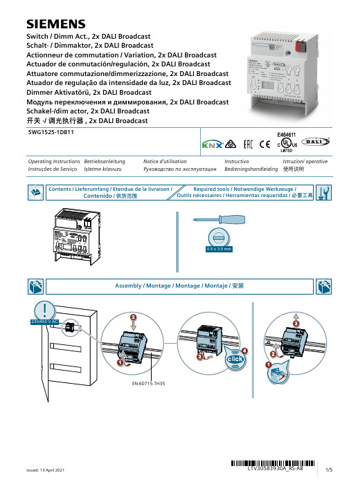
西门子 5WG1525-1DB11 开关 调光执行器说明书
sOperating Instructions Betriebsanleitung Notice d'utilisationInstructivo Istruzioni operative Instruções de Serviço İşletme kılavuzu Руководство по эксплуатацииBedieningshandleiding 使用说明5WG1525-1DB11Switch / Dimm Act., 2x DALI Broadcast Schalt- / Dimmaktor, 2x DALI BroadcastActionneur de commutation / Variation, 2x DALI Broadcast Actuador de conmutación/regulación, 2x DALI BroadcastAttuatore commutazione/dimmerizzazione, 2x DALI Broadcast Atuador de regulação da intensidade da luz, 2x DALI Broadcast Dimmer Aktivatörü, 2x DALI BroadcastМодуль переключения и диммирования, 2x DALI Broadcast Schakel-/dim actor, 2x DALI Broadcast 开关-/ 调光执行器, 2x DALI BroadcastF0F4F5F6EN Illuminant defective DALI incorrect voltage DALI short circuit No ECG foundDE Leuchtmittel defekt Fremdspannung DALI Kurzschluss Kein EVG gefundenFR Lampe défectueuse Tension externe Court-circuit DALI Pas de ballast électronique trouvéES Fuente de luz defectuosa Tensión externa Cortocircuito DALI No se ha encontrado ningún balastoelectrónicoIT Lampada difettosa Tensione parassita Cortocircuito DALI Nessun reattore elettronico trovato PT Lâmpada com defeito Tensão externa Curto-circuito em DALI Nenhum balastro eletrónico encontrado TR Ampul bozuk Harici gerilim DALI kısa devre Elektronik balast bulunamadıРУНеисправен источник светаНапряжение от внешнегоКороткое замыкание DALIНе найден ЭПРАисточникаPL Lampa uszkodzona Napięcie zewnętrzne Zwarcie DALI Nie odnaleziono statecznika elektronicz-nego中灯具损坏外部电压 DALI 短路未找到 EVG© Siemens Schweiz AG 2019Subject to change without prior notice. Store for use at a later date."Technical Documentation:/gamma-tdTechnical Support/supportrequest)$4FAQ:https:///cs/ww/en/ps/faqListing and CertificationscUL listed (E464611)UL 916, Open Energy Management Equipment Electromagnetic compatibilityUSA:This device complies with part 15 of the FCC Rules. Operation is subject to the following two conditions:(1) This device may not cause harmful interference, and(2) this device must accept any interference received, including interference that may cause undesired operation.This equipment has been tested and found to comply with the limits for a Class B digital device, pursuant to part 15 of the FCC Rules. These limits are designed to provide reasonable protection against harmful interference in a residential installation. This equipment generates, uses and can radiate radio frequency energy and, if not installed and used in accordance with the instructions, may cause harmful interference to radio communications. However, there is no guarantee that interference will not occur in a particular installation. If this equipment does cause harmful interference to radio or television reception, which can be determined by turning the equipment off and on, the user is encouraged to try to correct the interference by one or more of the following measures:- Reorient or relocate the receiving antenna.- Increase the separation between the equipment and receiver.- Connect the equipment into an outlet on a circuit different from that to which the receiver is connected.- Consult the dealer or an experienced radio/TV technician for help.This device complies with Part 15 of the FCC rules. Changes or modifications not expressly approved by Siemens Schweiz AG could void the user’s authority to operate the equipment.United States representative:https:///us/en/products/buildingtechnologies/home.html Canada:CAN ICES-3(B)/NMB-3(B)(1) This equipment is intended for field installation within the enclosure of another product.WARNINGHazardous voltage.Can cause death, serious injury or property damage.The Device must not be opened.A faulty device should be returned to the local Siemens sales office or distributor.The device must be mounted and commissioned by a factory trained person.The prevailing safety rules must be observed!Mount in dry location only!。
西门子 ZSE40A ZSE40AF ISE40A 数字压力开关 安装维修手册说明书
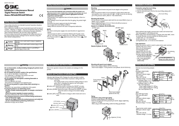
Installation & Maintenance ManualDigital Pressure SwitchSeries ZSE40A/ZSE40AF/ISE40AThese safety instructions are intended to prevent hazardous situations and/or equipment damage.These instructions indicate the level of potential hazard with the labels of "Caution", "Warning" or "Danger". They are all important notes for safety and must be followed in addition to International standards (ISO/IEC), Japan Industrial Standards (JIS) and other safety regulations.To ensure safety of personnel and equipment the safety instructions in this manual and the product catalogue must be observed, along with other relevant safety practices.•Do not touch the terminals and connectors while the power is on. Otherwise electric shock, malfunction or damage to the product can result.•After maintenance is complete, perform appropriate functional inspections and leak tests.Stop operation if the equipment does not function properly or there is a leakage of fluid.When leakage occurs from parts other than the piping, the product might be faulty.Disconnect the power supply and stop the fluid supply.Do not apply fluid under leaking conditions.Safety cannot be assured in the case of unexpected malfunction.NOTE•The direct current power supply to be used should be UL approved as follows:Circuit (of class 2) which is of maximum 30Vrms (42.4V peak) or less, with UL 1310 class 2 power supply unit or UL 1585 class 2 transformer.•The Pressure switch is a approved product only if it has a mark on the body.CautionInternal Circuit and Wiring•Internal circuit and wiring examplePressure SettingMaintenanceSettingDefault settingAt the time of shipment, the following settings are provided.If the setting is acceptable, keep it for use.To change setting, enter function selection mode .Other Functions•Peak/Bottom hold value indication•Zero clear•Key lockTo set each function in detail, refer to the operation manual on thewebsite.How to reset the product after power cut or forcible de-energizingThe setting of the product will be retained as it was before a power cut orde-energizing. The output condition is also basically recovered to thatbefore a power cut or de-energizing, but may change depending on theoperating environment.Therefore, check the safety of the whole facility before operating theproduct. If the facility is using accurate control, wait until the pressureswitch has warmed up. (About 10 to 15 minutes)To set each function in detail, refer to the operation manual on the website.Set ON point and OFF point of the Pressure switch.OperationWhen the pressure exceeds a set value, the Pressure switch will beturned on.When the pressure falls below the set value by the amount of hysteresisor more, the Pressure switch will be turned off.The default setting of the output set value is the central value betweenthe atmospheric pressure and the upper limit of the rated pressurerange. If the operation shown below does not cause any problem, keepthis operation setting.The Pressure switch turns on within a set pressure range (from P1L to P1H)during window comparator mode.Set P1L (switch lower limit) and P1H (switch upper limit) using the settingprocedure above.•[F 2] Setting of OUT2Same setting as [F 1] OUT1.At the output mode, Error detection mode can be selected.Display colour is linked to the setting of OUT1, and can not be selected.Measurement modeThe measurement mode is the condition where the pressure is detected andindicated, and the switch function is operating.This is the basic mode, and other modes should be selected for settingchange and other function setting changes.•Window comparator modeZISE##-TFM112GBSpecificationRefer to the operation manual on the website and catalogue for this product.Outline with Dimensions (in mm)Refer to the operation manual on the website and catalogue for this product.ContactAUSTRIA (43) 2262 62280 NETHERLANDS (31) 20 531 8888 BELGIUM (32) 3 355 1464 NORWAY (47) 67 12 90 20 CZECH REP.(420) 541 424 611 POLAND (48) 22 211 9600 DENMARK (45) 7025 2900 PORTUGAL (351) 21 471 1880FINLAND (358) 207 513513 SLOVAKIA (421) 2 444 56725 FRANCE (33) 1 6476 1000 SLOVENIA (386) 73 885 412GERMANY (49) 6103 4020 SPAIN (34) 945 184 100 GREECE (30) 210 271 7265 SWEDEN(46) 8 603 1200 HUNGARY (36) 23 511 390 SWITZERLAND (41) 52 396 3131 IRELAND (353) 1 403 9000 UNITED KINGDOM(44) 1908 563888ITALY(39) 02 92711URL (Global) (Europe)Specifications are subject to change without prior notice from the manufacturer. © 2009 SMC Corporation All Rights Reserved.Refer to the operation manual on the website for this product.If the error can not be reset after the above measures are taken, then please contact SMC.。
西门子 8BK20型 中压开关装置 说明书

5P10/10P10 5P15/10P15 5P20/10P20 5P25/10P25
10
12
16
20
10
16
20
23
12
20
23
31
16
20
27
35
16
23
31
9
10
13
16
9
13
16
21
11
16
21
27
13
18
23
29
14
21
27
35
10
10
11
14
11
11
16
19
11
14
19
23
11
16
23
27
或FS10 8 10 15
8 10 15
8 10 15
8 10 15
8(8) 8(10) 9(15)
10 10 8(8) 8(8) 9(11) 10 10 8 9 9 10 10 8(8) 8(10) 9(15) 10 10 8(8) 8(8) 8(9) 10 10
0.5FS10
8 8 11
8 8 11
0.5FS10
8 8 11
8 8 11
8 8 11
8 8 11
7(8) 8(8) 8(11)
9 10 7(7) 8(8) 8(9)
9 10 7 8 8 8 9 7(8) 8(8) 8(11) 9 10 8(7) 8(8) 8(8) 10 10
5P10/10P10 5P15/10P15 5P20/10P20 5P25/10P25
11(15) 13(22) 18(33) 19(38)
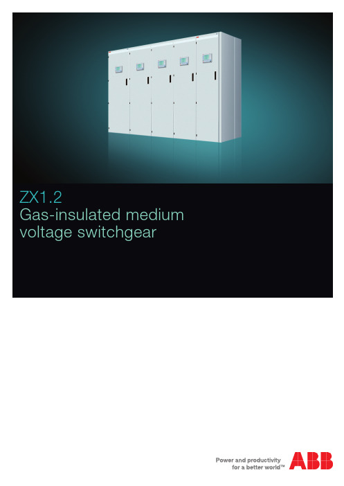
西门子 ZX1.2 气体绝缘中压开关柜使用指南说明书
8Feeder 2000 APlug-in voltage transformer – feederIsolating system for voltage transformerGas density sensor and filling valveMultifunctional protection and control unitVacuum circuit-breakerThree position disconnectorBusbarsPressure relief diskPressure relief ductInner cone cable connectorCable socketMeasuring sockets for capacitive voltage indicator system Test socketCurrent transformer or combined current and voltage sensor Plasma diverterTechnical dataRated voltage kVCable termination compartment with inner cone connectors Plug-in busbar connection Plugged-in voltage transformersAlways the right connectionIn the cable termination compartment with its extremely high termination point (1250 mm), the power cables are connected with inner cone cable connectors. Up to four parallel cables can be installed. A surge arrester can be fitted as an alterna-tive to one cable. A non-return valve on the SF6-filled stainlesssteel enclosure facilitates systematic extraction of the insulat-ing gas at the end of a panel’s service life.Current transformersGenerously dimensioned block-type current transformers with several cores supply the signals required for protec-tion and measurement.Voltage transformersShockproof voltage transformers are plugged into inner cone sockets. These are isolatable for test purposes, especially for cable testing.ContactD E A B B 2448 E N (12.10-1000-A M C )Note:We reserve the right to make technical changes or modify the contents of this document without prior notice. With regard to purchase orders, the agreed particulars shall prevail. ABB AG does not accept any responsibility whatsoever for potential errors or possible lack of informa-tion in this document.We reserve all rights in this document and in the subject matter and illustrations contained therein. Any reproduction, disclosure to third parties or utilization of its contents – in whole or in parts – is forbidden without prior written consent of ABB AG.Copyright© 2010 ABB All rights reservedABB AGCalor Emag Medium Voltage Products Oberhausener Strasse 33 40472 Ratingen, Germany Phone: +49(0)21 02/12-0 Fax: +49(0)21 02/12-17 77 E-mail: powertech@ABB AGCalor Emag Medium Voltage Products Petzower Strasse 814542 Werder (Havel) OT Glindow, Germany Phone: +49(0)21 02/12-0 Fax: +49(0)21 02/12-17 77 E-mail: powertech@ /mediumvoltageYour sales contact: /contactsMore product information: /productguide。
- 1、下载文档前请自行甄别文档内容的完整性,平台不提供额外的编辑、内容补充、找答案等附加服务。
- 2、"仅部分预览"的文档,不可在线预览部分如存在完整性等问题,可反馈申请退款(可完整预览的文档不适用该条件!)。
- 3、如文档侵犯您的权益,请联系客服反馈,我们会尽快为您处理(人工客服工作时间:9:00-18:30)。
西门子开关(3AQ1 EE)说明一、技术数据:1、3AQ1 EE型开关是一种采用SF6气体作为绝缘和灭弧介质的压气式高压开关,三相设计户外式。
灭弧所需的灭弧介质压力在分闸过程中通过灭弧单元中的一个压气活塞设备形成。
开关的每个相装有一液压操作机构,以使开关适用于单相的和三相的自动重合闸。
2、本开关适用的环境温度范围为:-25℃至+50℃。
3、符合IEC标准的绝缘水平:额定电压:252kV额定工频耐压在50Hz时对地:460kV 断口间:460kV 相间:460kV最大额定雷电冲击电压(1.2/50μs)对地:1050kVmax 断口间:1050kVmax相间:1050kVmax绝缘距离对地:2×1100mm 断口间:1900mm 相间:3055/2455mm最小爬距:对地大-小-绝缘子裙:6300mm断口间大-小-绝缘子裙:7595mm4、电气数据:额定电压:252kV额定频率:50Hz额定电流:3150/4000A额定短路开断电流:50kA额定关合电流:2.5×额定短路开断电流额定短路持续时间:3s额定操作程序:O-0.3s―CO―3min―CO5、开关动作时间:指令最小持续时间:50ms合闸时间:105±5ms分闸时间:36±3ms燃弧时间:max21ms开断时间:max60ms合-分-时间:58±12ms间隔时间:300ms6、液压压力监视:动作值安全阀:375/37.5bar/MpaN2泄漏:355/35.5 bar/Mpa液压泵“合”:320/32.0 bar/Mpa自动重合闸闭锁:308/30.8 bar/Mpa合闸闭锁:273/27.3 bar/Mpa总闭锁:253/25.3 bar/Mpa7、灭弧介质SF6:额定电压:252kV每台开关的充气量:20kg每台开关的充气体积:335dm320℃时的额定压力:7.0/0.7 bar/MpaSF6监控20℃时“SF6泄漏”信号:6.4/0.64 bar/Mpa20℃时总闭锁:0.2/0.02 bar/Mpa在“SF6泄漏”信号以下机械开断时SF6的最小压力:3.0/0.3 bar/Mpa每个极柱的过滤材料:4.5kg8、液压操作机构:液压储能筒的容量:14dm3油量(整台开关):25 kg20℃时N2的预充压力:200-5/20-0.5 bar/Mpa压力范围:250···375/25.0···37.5 bar/Mpa储存的操作程序:CO-15s-COO-0.3S―CO―3min―CO油泵:300bar时的供油量:0.9 dm3/min直流电源0.7 dm3/min交流电源额定电压:208/120 220/127 230/133 380/220 400/230 415/240 440/254 480/280 操作箱:45W液压操作机构:2×15W11、辅助开关:型号:3SV 92额定电压:250V DC持续电流:10A可自由支配的触头:4NC,4NO,2滑动触头开断容量:电阻性负载常闭触头和常开触头:2.5A滑动触头:2.5A电阻电感性负载:2A时间常数τ:20ms二、开关构造:1)开关基架2)控制箱3)液压储能筒4)液压操作缸5)绝缘子6)灭弧室三个开关相安装在同一个开关基架上,此开关基架作为底架或支架组成底座构造。
开关相充了SF6气体作为灭弧和绝缘介质。
这三个开关相经由管道与一个气室相连,SF6气体密度由一只密度计监控,压力由一只压力表显示。
液压压力由压力监控器监控并通过一只压力表显示。
此开关具有三个液压操作机构,它们都固定在开关基架上。
操作能量将通过液压储能筒中压缩氮气储存。
固定在开关基架上的控制箱中,装有用于开关控制和监测的设备以及所需的接线端子排。
三、开关的液压操作机构此液压操作机构是专用于这种开关结构系列的,它由下述部件组成:1、液压操作机构2、液压储能筒3、控制单元1)液压操作机构的构造:液压缸、油箱、阀块、视孔玻璃、开关状态显示器。
液压操作机构的作用原理:a)合闸过程:分闸状态:开关处于分闸状态。
液压缸中差动活塞分闸一侧是承压油,合闸一侧是无压油,由此确保开关处于分闸状态。
这也适用于液压系统中压力波动的情况。
合闸指令:为了合闸,通过合闸电磁铁操纵合闸阀,承压油打开逆止阀并作用在主阀的阀活塞上,使···合闸起始运动:···主阀的阀活塞打开。
这样,液压缸差动活塞的合闸一侧也处在承压油下,承压油经阀块上的喷嘴到达主阀的阀活塞;主阀由此保持打开状态,即使合闸指令中断或合闸控制阀关闭也不变(通过直接与液压储能筒相连的液压自闭塞)。
主阀的阀活塞在打开后,封闭与系统无压部分的连接。
因为液压缸中差动活塞的合闸一侧具有比分闸一侧较大的面积,所以开关合闸。
在合闸过程中,承压油从差动活塞的分闸一侧流经主阀达到差动活塞的合闸一侧,承压油的差额油量由液压储能筒弥补。
合闸状态:开关处于合闸状态。
液压缸中的差动活塞的分闸一侧和合闸一侧都处于压力下,因为差动活塞的合闸一侧具有较大的面积,所以此面所受的力大,这样,开关保持合闸状态。
这也适用于液压系统中压力波动的情况。
主阀保持自闭塞。
b)分闸过程:分闸指令:为了分闸,通过分闸电磁铁控制分闸阀,由此打通了原一直封闭的承压油至油箱的油路(分闸阀的阀球与主阀的阀活塞之间)。
分闸起始运动:主阀关闭了承压的一侧并打开无压的一侧,由此打通了液压缸中差动活塞的合闸一侧的承压油至油箱的油路。
此时,承压油只作用在差动活塞的分闸一侧,从此使开关分闸。
2)液压储能筒:每台开关装有一只液压储能筒,操作能量储存在此储能筒内(N2充填)。
液压储能筒由一泵管注入油,一根高压油管连接着操作机构和储能筒。
此液压储能筒是一种活塞储能筒,可自由移动的活塞将氮气(N2)与液压油隔开。
液压储能筒的工作原理:液压储能筒是预充了氮气提供的,活塞在预充压力的作用下处于油的一侧液压缸壁。
在开关投运时,油泵将油打入液压储能筒,直至达到最大运行压力,油将活塞压往氮气一侧,由此提高了氮气一侧的压力。
会造成液压储能筒中压力下降到因素有:操作、内部泄漏(在液压回路中部份存在,即使开关不操作,油泵系统也会时时工作)、环境温度下降、氮气泄漏。
当压力降至压力监控器的动作压力以下时,泵接通,它将油从油箱重新打入液压储能筒。
当压力达到动作压力时,通过压力开关以及一只连着的时间继电器,在约3秒之后泵重新停止。
在达到“N2泄漏”压力时,压力监控器动作并作出:a.在时间继电器生效之前,油泵组合迅速停机;b.“N2泄漏”信号;c.开关闭锁,立即不能合闸,通过一只时间继电器延时3小时之后(标准调节),开关不能分闸。
液压储能筒的工作能力确保还有足够的液压压力,在出现“N2泄漏”信号之后的固定时间内可以分闸。
为了避免任何情况下液压系统中出现过高的压力-例如由气温升高引起,安装了一只安全阀。
此安全阀在压力达到安全阀动作压力时动作,并将油经一条旁路从液压系统的高压一侧导向无压一侧(油箱)。
3)控制箱:控制箱内包含了所有用于开关运行、观察和控制所需的部件。
液压压力由压力监控器控制并由控制元件监测,气体压力只是控制。
用于防止电器部件上形成冷凝水的加热器,对确保控制箱中各部件的完好功能非常重要。
各个功能的元件归列在一起,电气连接通过螺栓压接或插座连接完成。
控制箱的基本装置及主要部件:耐气候、通风及加热的控制箱;SF6压力表;油泵单元;液压监控单元及压力表;密度计;接触器、继电器、时间继电器;用于防止形成冷凝水的加热器;端子接头。
油泵单元:由电动机和油泵组成,电动机由液压监控单元(接触器、继电器、时间继电器)控制。
液压监控单元:是一个紧密组件,单个的组合件集成在一个油监测块内。
在油监测块内包括铅封的安全阀、泄压阀和一只逆止阀,用于液压储能筒承压的情况下油泵的释压。
压力监控器通过电气触头监测和控制液压压力,从压力表上可以读取运行正常的油压。
气体监控单元:密度计安装在控制箱的后壁上,电气接头为了防止冷凝水布置在控制箱内。
从压力表上可以读取运行正常的气压。
接触器、继电器、时间继电器:开关接触器用来控制开关操作机构中具有较大功率消耗的部件(电动机和脱扣器)。
为了开关的监控,使用了带高接触可靠性触头的继电器。
继电器插装在继电器板的插座上并用卡锁夹紧,继电器板通过插头与接线板以及端子排上别的控制连接。
四、运行注意事项:1、开关只能通过控制室内或在就地控制箱内的按钮操作。
2、极柱中SF6气体的压力由一密度计监控并显示在一压力表上。
在SF6压力出现不正常下降时,会显示“SF6泄漏”信号。
开关应立即分闸,SF6气体必须尽快予以补充,直至达到额定的气体压力。
补充结束后,开关可以重新合闸。
3、如果开关中SF6压力下降到不能保障可靠熄弧时,总闭锁生效。
开关所有的操作都将无法执行。
4、SF6压力低于3bar/0.3Mpa时,开关不允许操作。
5、液压操作系统中的油压由控制箱中的密度计监控并显示。
当液压操作系统中油压下降过多时会发出信号并发生闭锁,直至油自动打压至分、合闸操作所需的压力。
6、由于液压系统中高压部分和无压部分之间的泄漏,压力会产生缓慢的下降。
因此,油泵单元起动,液压监控系统执行不间断的检查。
油泵打压的间隔时间大于1小时是正常的,如果打压的间隔时间小于1小时,请通知有关部门。
7、如果油泵在较短的时间间隔后起动,请注意此间隔时间。
当间隔时间小于1小时,存在着外部泄漏或不正常的内部泄漏。
