STM8CAN过滤器理解
小菲教你STM8单片机基础入门

速度达20 MIPS的高性能内核 抗干扰能力强,品质安全可靠 领先的130纳米制造工艺,优异的性价比 程序空间从4K到128K, 芯片选择从20脚到80脚,宽范围产品系列 系统成本低,内嵌EEPROM和高精度RC振荡器 开发容易,拥有本地化工具支持
STM8S主要应用:
STM8L主要特点:
STM8 16 MHz CPU 内置 4-32 KB 闪存,多达 2KB SRAM 三个系列:跨系列的引脚对引脚兼容、软件相互兼容、外设相互兼容 电源电压:1.8 V-3.6 V (断电时,最低 1.65 V) 超低功耗模式:保持 SRAM 内容时,最低功耗 350nA 运行模式动态功耗低至 150μA/MHz 最先进的数字和模拟外设接口 工作温度范围:-40°C 到+85 °C,可高达 125 °C 免费的触感固件库
王志杰 Email: iewangzhijie@ QQ:411238869
1 STM8 微控制器简介
-7-
1.3 STM8A 系列
意法半导体公司推出的 STM8A 是一款专门用于满足汽车应用的特殊需求的 8-位 Flash 微控制器。这些模块化产品提供了真数据 EEPROM 以及软件和引脚兼容性,适用的程序存 储器尺寸范围为 8KB 至 256KB 和 20 至 128-引脚封装。所有器件的工作电压均为 3V 至 5V, 并且其工作温度扩展到了 145°C。
监控、紧急求助
王志杰 Email: iewangzhijie@ QQ:411238869
1 STM8 微控制器简介
-4-
STM8S 产品分为“Access Line(入门级)”和“Peroformance Line(增强型)”,如 下图所示。
王志杰 Email: iewangzhijie@ QQ:411238869
MSCAN通讯验收滤波器设计
MSCAN通讯验收滤波器设计吴成加【摘要】The author introduces the principle of MSCAN controller and the setting method of acceptance filters and shield codes for MSCAN when used in receiving multi-frame CAN information. He also gives out a design example of the acceptance codes and shield codes for receiving single or multi-frame information, so that the user can quickly set up in design.%介绍MSCAN 控制器及CAN滤波器的原理,应用于接收多帧CAN信息时MSCAN 的验收码及屏蔽码的设置方法,并给出一个用于接收单帧或多帧信息时的验收码、屏蔽码设计实例,便于用户在设计时进行快速设置。
【期刊名称】《客车技术与研究》【年(卷),期】2015(000)004【总页数】4页(P41-44)【关键词】汽车电子;MSCAN;验收滤波器;屏蔽码【作者】吴成加【作者单位】安徽安凯汽车股份有限公司,合肥 230051【正文语种】中文【中图分类】U463.61随着汽车电子化的提高和汽车CAN总线的普及,汽车电子控制单元的使用也越来越多。
电子控制单元可以通过CAN总线网络获得更多的信息,来实现更加精确的控制,达到信息与资源的共享。
网络接点的增加,同时也导致通讯信息量的增加。
对于CAN发送节点,其发送的数据可以被网络中的所有节点接收;对于接收节点,它能接收总线上的所有CAN帧信息。
各控制节点需要从众多的信息中,挑选自已所需的信息,对无用的信息进行剔除和信息过滤。
要想只获得某些特定的信息,需要根据所接收的ID信息设置自身CAN控制器的验收和屏蔽码,实现信息过滤。
STM32的CAN总线的标识符过滤器组使用注意事项
STM32的CAN总线的标识符过滤器组使用注意事项CAN 总线的标识符过滤器很重要。
1. 标识符过滤器是用于接收的,发送的时候无需设置过滤器,这点一定要整明白。
根据发送端发送来的帧数据,通过标识符过滤器就可以设置仅接收需要接收的帧数据有效降低CPU 多余的处理时间。
2 什么是标识符?标识符主要包括如下,也可以简单的理解仅包含ID 号,但是在这里下面这些都是要包含的。
比如:数据帧和遥控帧,标识符就包含在其中,所以发送端发帧数据给接收端后,接收端就可以通过硬件标识符过滤器进行筛选,节省了CPU 时间:3. 下面就是最重要的,STM32 的CAN 总线标识符滤波器组包含两种实现方法:屏蔽位模式和标识符列表模式,这两种方式怎么理解呢,重点看下面的截图:书面上解释屏蔽位模式和标识符列表模式的区别屏蔽位模式在屏蔽位模式下,标识符寄存器和屏蔽寄存器一起,指定报文标识符的任何一位,应该按照必须匹配或不用关心处理。
标识符列表模式在标识符列表模式下,屏蔽寄存器也被当作标识符寄存器用。
因此,不是采用一个标识符加一个屏蔽位的方式,而是使用2 个标识符寄存器。
接收报文标识符的每一位都必须跟过滤器标识符相同。
===================================标识符的列表模式比较好理解,就是指的所有的过滤器寄存器位全部用于过滤,简单的说就是发送端发送的标识符所有的位必须跟接收端的滤波器寄存器定义一样。
有一个位定义不一样,拒收此消息。
比STM32F103 有14 个过滤器组,如果采用两个16 位的过滤器形式,那么就可以固定识别出14 * 4 = 56 个不同的标识符,实际使用中也够用了。
为什么是乘以4,注意看上面的截图,4 个16 位过滤器--标识符列表===================================屏蔽位模式要稍麻烦一些,我们以2 个16 位过滤器---标识符屏蔽为例进行。
CAN的工作原理
CAN的工作原理标题:CAN的工作原理引言概述:Controller Area Network(CAN)是一种用于实时控制系统的串行通信协议,广泛应用于汽车、工业控制和航空航天等领域。
CAN的工作原理是通过一种高效的通信方式,实现多个节点之间的数据传输和控制。
一、CAN的物理层1.1 CAN总线结构CAN总线由两根导线组成,分别是CAN-H和CAN-L,采用差分信号传输方式。
1.2 电压水平CAN总线的电压范围为0-5V,CAN-H高电平对应CAN-L低电平,反之亦然。
1.3 抗干扰能力CAN总线具有较强的抗干扰能力,能够在恶劣环境下稳定传输数据。
二、CAN的数据链路层2.1 帧格式CAN数据帧由起始位、标识符、控制位、数据域、CRC校验和结束位组成。
2.2 帧类型CAN数据帧分为数据帧和远程帧两种类型,用于实现数据的传输和请求。
2.3 确认机制CAN数据帧通过确认机制确保数据的可靠传输,发送节点会等待接收节点的确认信号。
三、CAN的网络层3.1 节点通信CAN网络中的节点通过标识符进行通信,标识符的优先级决定了数据传输的顺序。
3.2 数据传输CAN网络中的节点可以同时发送和接收数据,实现实时的数据交换和控制。
3.3 网络拓扑CAN网络支持多种拓扑结构,如总线、星型和树型,适用于不同的应用场景。
四、CAN的协议层4.1 帧过滤CAN协议支持帧过滤功能,可以根据标识符过滤接收的数据帧,提高系统的效率。
4.2 错误处理CAN协议具有强大的错误处理能力,能够检测和纠正数据传输过程中的错误。
4.3 速率控制CAN协议支持不同的数据传输速率,可以根据应用需求调整通信速度。
五、CAN的应用领域5.1 汽车行业CAN总线在汽车电子系统中广泛应用,如引擎控制、制动系统和空调控制等。
5.2 工业控制CAN总线在工业自动化领域中起到关键作用,实现设备之间的实时通信和协作。
5.3 航空航天CAN总线被应用于航空航天领域,用于飞行控制系统和航空电子设备的数据传输。
can总线标识符过滤器难点解析

can总线标识符过滤器难点解析下载提示:该文档是本店铺精心编制而成的,希望大家下载后,能够帮助大家解决实际问题。
文档下载后可定制修改,请根据实际需要进行调整和使用,谢谢!本店铺为大家提供各种类型的实用资料,如教育随笔、日记赏析、句子摘抄、古诗大全、经典美文、话题作文、工作总结、词语解析、文案摘录、其他资料等等,想了解不同资料格式和写法,敬请关注!Download tips: This document is carefully compiled by this editor. I hope that after you download it, it can help you solve practical problems. The document can be customized and modified after downloading, please adjust and use it according to actual needs, thank you! In addition, this shop provides you with various types of practical materials, such as educational essays, diary appreciation, sentence excerpts, ancient poems, classic articles, topic composition, work summary, word parsing, copy excerpts, other materials and so on, want to know different data formats and writing methods, please pay attention!CAN总线标识符过滤器难点解析CAN总线是一种广泛应用于汽车、工业控制等领域的通信总线标准,而CAN总线标识符过滤器是CAN控制器中的关键部分。
STM32之CAN ---CAN ID过滤器分析
前言在CAN协议里,报文的标识符不代表节点的地址,而是跟报文的内容相关的。
因此,发送者以广播的形式把报文发送给所有的接收者。
节点在接收报文时,根据标识符(CAN ID)的值决定软件是否需要该报文;如果需要,就拷贝到SRAM里;如果不需要,报文就被丢弃且无需软件的干预。
为满足这一需求,bxCAN为应用程序提供了14个位宽可变的、可配置的过滤器组(13~0),以便只接收那些软件需要的报文。
硬件过滤的做法节省了CPU开销,否则就必须由软件过滤从而占用一定的CPU开销。
每个过滤器组x 由2个32位寄存器,CAN_FxR0和CAN_FxR1组成。
为了让大家了解STM32的bxCAN的接收过滤机制,首先大家需要了解几个概念。
2 几个重要的概念2.1 过滤器组STM32总共提供14个过滤器组来处理CAN接收过滤问题,每个过滤器组包含两个32位寄存器CAN_FxR0和CAN_FxR1组成,在设置为屏蔽位模式下,其中一个作为标识符寄存器,另一个作为屏蔽码寄存器。
过滤器组中的每个过滤器,编号(叫做过滤器号)从0开始,到某个最大数值(这时最大值并非13,而是取决于14个过滤器组的模式和位宽的设置,当全部配置为位宽为16,且为标识符列表模式时,最大编号为14*4-1=55)。
2.2 过滤器的过滤模式STM32提供两种过滤模式供用户设置:屏蔽位模式和标识符列表模式。
2.2.1 屏蔽位模式为了过滤出一组标识符,应该设置过滤器组工作在屏蔽位模式。
在屏蔽位模式下,标识符寄存器和屏蔽寄存器一起,指定报文标识符的任何一位,应该按照“必须匹配”或“不用关心”处理。
2.2.2 标识符列表模式为了过滤出一个标识符,应该设置过滤器组工作在标识符列表模式。
在标识符列表模式下,屏蔽寄存器也被当作标识符寄存器用。
因此,不是采用一个标识符加一个屏蔽位的方式,而是使用2个标识符寄存器。
接收报文标识符的每一位都必须跟过滤器标识符相同。
2.3 过滤器的位宽每个过滤器组的位宽都可以独立配置,以满足应用程序的不同需求。
STM8学习笔记——初步认识

STM8学习笔记——初步认识最近项目要求找个便宜又够用的单片机,本来是想选STC 的,但其实STC 也并不便宜,且调试比较麻烦,而且AD 不是很好,所以选择了STM8。
昨天买来了ST-LINK III,拿了一块STM8S105S4,此单片机有16K ROM,2K RAM,1K 的EEPROM,带10bitADC,定时器(ICOCPWM)和SPI I2C UART 通讯接口,看门狗等,封装为LQFP44。
这款单片机的供电分得很细,主电源、IO 口、模拟供电都分开,这样就可以非常灵活的配置,比如模拟供电可以选用5V 以扩大量程;IO 口可以配置位3.3 或5V 以适应一些设备。
上图中VDD/VSS 引脚用于给内部主电压调节器(MVR)和内部低功耗电压(LPVR)调节器供电。
这两个调节器的输出连接在一起,向MCU 的核(CPU,FLASH 和RAM)提供1.8V 电源(V18)。
在低功耗模式下,系统会将供电电源从MVR 自动切换到LPVR 以减少电流消耗。
为稳定MVR,在VCAP 引脚必须连接一个电容。
该电容应该拥有较低的等效串联电阻值(ESR),电容最小的推荐容值为470nF。
ST-LINK III 管脚定义及接法:ST-LINK III LED 灯三种状态含义:常亮:目标板与ST-LINK 在SWIM 模式或者JTAG/SWD 模式下已经通讯初始化。
闪烁:目标板与ST-LINK 正在进行数据交换。
熄灭:目标板与ST-LINK 没有通讯初始化。
开发平台:还是比较习惯用IAR,查了下果然有IAR for STM8,于是下了并和谐,然后随便写了个程序,下载调试,发现出错,更新ST-LINK III 的固件,无果。
难道是IAR 的问题?于是下载官方的STVD,安装后发现也无法下载,提示是。
gd32 can过滤器理解

gd32 can过滤器理解
GD32 CAN过滤器是指在GD32微控制器中用于CAN总线通信的
过滤器功能。
CAN总线是一种常用的实时通信协议,用于在微控制
器和外部设备之间进行数据传输。
过滤器的作用是在CAN总线接收
数据时,根据特定的标识符或数据内容来过滤出需要的数据帧,从
而提高系统的效率和稳定性。
首先,GD32 CAN过滤器可以根据标准帧和扩展帧的标识符进行
过滤。
标准帧使用11位标识符,而扩展帧使用29位标识符,过滤
器可以根据这些标识符来过滤出需要的数据帧。
这样可以避免系统
处理大量不必要的数据,提高系统的响应速度和效率。
其次,GD32 CAN过滤器还可以根据数据帧的接收方向进行过滤。
这意味着可以设置过滤器只接收特定方向的数据帧,例如只接收发
送到本地节点的数据或者只接收来自其他节点的数据,从而确保系
统只处理必要的数据。
此外,GD32 CAN过滤器还支持多个过滤器的组合设置,可以根
据实际需求设置多个过滤条件,以满足复杂的通信环境和应用场景。
总的来说,GD32 CAN过滤器提供了灵活、高效的数据帧过滤功能,可以帮助系统精确地接收和处理CAN总线上的数据,提高系统的稳定性和可靠性。
通过合理设置过滤器,可以有效地减少系统的通信负担,提高系统的性能和响应速度。
CAN标识符 过滤器 屏蔽器之间的关系
C A N标识符、过滤器、屏蔽器之间的关系【问】看了好多遍数据,也没搞明白CAN的标识符、CAN接收过滤器和CAN接收屏蔽器之间有什么关系,单独看都明白,一旦联系起来就胡涂了。
在一个主控制器对多点通讯网络中,它们各自如何配置,主机要想发信息给所有的从机,和主机想发信息给某个特定的从机,应该怎么配置这几个寄存器呢?【回答】CAN节点通过标识符来识别CAN帧是不是自己想要的,识别方法就是通过滤波屏蔽寄存器的设置来完成,接收滤波寄存器设置了标识符每位的值,接收屏蔽寄存器一般有相同的数量匹配接收滤波寄存器,规定接收滤波寄存器标识符每一位的值是否需要进行匹配,比如芯片设置有6个接收滤波寄存器和6个接收屏蔽寄存器,从总线上接收CAN帧,然后依次将收到的CAN帧标识符与6对接收滤波和屏蔽寄存器进行匹配,符合某对接收滤波和屏蔽寄存器要求了,就停止匹配,将数据接收到对应的缓冲区中.例如:设置某接收滤波寄存器00000000001(11位),接收屏蔽寄存器11111111101(11位),则该对组合会拒绝接收00000000011和00000000001之外所有的标识符对应的CAN帧,因为屏蔽器规定第二位(为0)以外的所有标识符位要严格匹配(与滤波器值一致),第二位的滤波器值和收到的CAN标识符第二位值是否一致都可以。
不同的芯片滤波屏蔽寄存器的运行方式不太一致,至少我用过的A T90CAN128和MCP2515差别就很大,不过原理都一样。
【问】初学CAN的朋友应该都会遇到我这样的问题,我的理解是,一个节点向网络中发送一条信息,所有的节点都能收到,收到后每个节点将收到的标识符自行与自己的比较,符合的才接收,过滤器和屏蔽器决定标识符中哪些位参与比较,也就是说有些位可以不参与比较就直接接收,这很有用,比如,11位的标识符不可能都用来标识下位机号,你一个网络不可能连接那么多节点,11位的标识符有点浪费,我们可以将最高3位用来表示所发送的数据类型,在接收点设置滤波器和屏蔽器只比较节点号部分,先将数据接收下来,在将最高3位拿来判断是什么数据,我的试验结果是RXB0SIDH会被发送端的TXB0SIDH修改,判断RXB0SIDH的最高三位即可知道接收的数据类型,以上是我这几天的学习结果,希望大家共同讨论。
stm8can标识符过滤器理解【可编辑】
STM8 CAN标识符过滤器理解CAN的两座大山一座是位时间和同步昨天被我们推倒后紧接着今天另一座标识符过滤器再一次被我们打倒,下面是我的理解如有误高手请拍砖!STM8的CAN有6个过滤器组:根据配置,每1组过滤器组可以有1个,2个或4个过滤器.这些过滤器相当于关卡,每当收到一条报文时,CAN要先将收到的报文从这些过滤器上"过滤"一下,能通过的报文是有效报文,收进FIFO中,不能通过的是无效报文(不是发给"我"的报文),直接丢弃.所有的过滤器是并联的,即,一个报文只要通过了一个过滤器,就是算是有效的.每组过滤器组有两种工作模式: 标识符列表模式,标识符屏蔽位模式.在标识符列表模式下,收到报文的标识符必须与过滤器的值完全相等,才能通过.在标识符屏蔽位模式下,可以指定标识符的哪些位为何值时,才能通过.这其实就是限定了处于某一范围的标识符能够通过.在一组过滤器中,整组的过滤器都使用同一种工作模式.另外,每组过滤器中的过滤器宽度是可变的,可以是32、16、8位由工作模式和宽度,一个过滤器组可以变成以下几中形式之一:(1) 1个32位的屏蔽位模式的过滤器。
2个32位的列表模式的过滤器。
(2) 2个16位的屏蔽位模式的过滤器。
4个16位的列表模式的过滤器。
2个16位的列表模式过滤器和1个屏蔽位模式过滤器。
(3)1个16位的屏蔽位模式的过滤器和2个8位屏蔽位模式的过滤器。
2个16位的列表模式的过滤器和2个8位的屏蔽位模式的过滤器。
1个16位的屏蔽位模式的过滤器和4个8位的列表模式的过滤器。
2个16位的列表模式过滤器和4个8位的列表模式的过滤器。
(4) 4个8位的屏蔽位模式的过滤器。
4个8位列表模式的过滤器和2个8位的屏蔽位模式的过滤器。
8个8位的列表模式的过滤器。
所有的过滤器是并联的,即,一个报文只要通过了一个过滤器,就是算是有效的.每组过滤器组有8个8位的寄存器用于存储过滤用的"标准值",分别是CAN_FxRi[i(1...8),x(0...8)]在32位的屏蔽位模式下:有1个过滤器,FxR[5...8]用于指定需要关心哪些位,FxR[1...4]用于指定这些位的标准值在32位的列表模式下:有两个过滤器.FxR[1...4]指定过滤器0的标准值,收到报文的标识符只有跟FxR[1...4]完全相同时,才算通过.FxR[5...8]指定过滤器1的标准值.在16位的屏蔽位模式下:有2个过滤器.FxR[1...4]配置过滤器0,其中,[31-16]位指定要关心的位,[15-0]位指定这些位的标准值.FxR[5...8]配置过滤器1,其中,[31-16]位指定要关心的位,[15-0]位指定这些位的标准值.在16位的列表模式下:有4个过滤器.FxR[1...2]配置过滤器0,FxR[3...4]配置过滤器1FxR[5...6]配置过滤器2,FxR[7...8]配置过滤器3.其他模式类似这里我就不一一举例了。
LPC系列ARM微控制器的CAN接收过滤设置
LPC2000系列32位ARM微控制器的CAN接收过滤设置控制器局域网(CAN)是一种串行通讯协议,它能有效支持高安全等级的分布实时控制。
CAN的应用范围很广,从高速的网络到低价位的多路接线都可以使用CAN。
LPC2119/2129/2290/2194/2292/2294 系列ARM芯片可同时支持对多个CAN总线的操作,使器件可用作网关、开关或工业或汽车应用中多个CAN总线的路由器。
LPC2000系列32位ARM微控制器集成有2个(LPC2119/2129/2290/2292)或4个(LPC2194/2294)CAN 控制器,每一个CAN控制器都与独立CAN控制器SJA1000有着相似的寄存器结构,只是器件的寄存器访问由原来的8bit字节访问转变为了32bit的双字访问,其主要的区别在于标识符接收过滤的编程操作上。
在传统的SJA1000中,接收过滤只能满足一些规律性较高的ID筛选过滤,或个数较少的ID(一般小于10~15个)进行任意筛选过滤,难以实现更复杂的任意ID进行筛选过滤,这无疑增加了系统软件设计及运行时负担。
LPC2000系列32位ARM微控制器中为所有CAN控制器提供了全局的接收标识符查询功能。
它包含一个512×32(2k字节)的RAM,通过软件处理,可在RAM中存放1~5个标识符表格。
整个AF RAM可容纳1024个标准标识符或512个扩展标识符,或两种类型混合的标识符。
由于允许的表格范围有2k字节,所以能容易地满足设计复杂的ID接收过滤要求。
首先概括性描述全局接收过滤的工作流程:当CAN控制器的接收端已接收到一个完整的标识符,它将通知接收过滤器。
接收过滤器响应这个信号,并读出控制器编号、标识符尺寸(11bit或29bit),然后,接收过滤器搜索AF RAM中的表格进行匹配,以决定接收或放弃这一帧信息。
如果FullCAN模式使能,且CAN控制器告知当前信息包含一个标准标识符,则接收过滤器(AF)首先查询FullCAN标准标识符表格,以便接收可在FullCAN模式下处理。
CAN总线系列讲座第六讲 ——SJA1000的滤波器设置
CAN总线系列讲座第六讲——SJA1000的滤波器设置CAN总线的滤波器设置就像给总线上的节点设置了一层过滤网,只有符合要求的CAN信息帧才可以通过,其余的一概滤除。
在验收滤波器的帮助下,只有当接收信息中的识别位和验收滤波器预定义的值相等时,CAN 控制器才允许将已接收信息存入RXFIFO。
验收滤波器由验收代码寄存器(ACRn)和验收屏蔽寄存器AMRn 定义,要接收的信息的位模式在验收代码寄存器中定义,相应的验收屏蔽寄存器允许定义某些位为“不影响”,即可为任意值。
1、BasicCAN模式下SJA1000滤波器在验收滤波器的帮助下CAN 控制器能够允许RXFIFO 只接收同识别码和验收滤波器中预设值相一致的信息,验收滤波器通过验收代码寄存器ACR和验收屏蔽寄存器AMR来定义。
表2-1验收代码寄存器ACR复位请求位被置高,验收代码寄存器ACR可以访问(读/写)。
表2-2验收屏蔽寄存器AMR复位请求位被置高,验收屏蔽寄存器AMR可以访问(读/写)。
验收屏蔽寄存器定义验收代码寄存器的相应位对验收滤波器是“相关的”或“无影响的”。
滤波的规则是:每一位验收屏蔽分别对应每一位验收代码,当该位验收屏蔽位为“1”的时候(即设为无关),接收的相应帧ID位无论是否和相应的验收代码位相同均会表示为接收;当验收屏蔽位为“0”的时候(即设为相关),只有相应的帧ID位和相应的验收代码位值相同的情况才会表示为接收。
只有在所有的位都表示为接收的时候,CAN控制器才会接收该报文。
举例:如何设置滤波器,接收标识符为0000 1010的CAN帧?在SJA1000复位模式下,设置寄存器CDR.7为“0”,即设置CAN控制器SJA1000工作于BasicCAN模式。
设置验收代码寄存器ACR0=0x0A;根据滤波器信息帧与滤波器的位对应关系,将需要参与滤波的信息位对应的验收屏蔽寄存器位设置为0,设置AMR=0x00;如此设置,SJA1000接收标识符ID.10~ID.3为0000 1010的CAN帧。
STM8教程-第四章 熟悉STM8微控制器

第四章熟悉STM8微控制器本章介绍STM8 系列的三个分支,最后结束STM8 的指令系统,相信对读者更深入了解STM8 有一定的帮助。
4.1 为什么选择STM8在嵌入式系统不断追求更高频率,更大容量存储器,更丰富内部资源和更高位数的CPU 时,为什么还需要8 位机的存在?当然8 位处理器已经不能再胜任一些复杂的应用,但是8 位微控制器的数量上的使用依然每年递增。
而STM8 系列最高可以高达24MHz 的主频和128KB 的Flash 与16 位或者低端32 位并没有多大差距,而在8 位微控制器中性能远远领先其它8 位微控制器。
4.2 STM8 微控制器系列ST 公司在STM32 发展到红红火火的时候开发了STM8 系列,补充8 位微控制器中高性能的空白。
ST 的8 位微控制器平台基于高性能8 位内核,配有先进的成套外设。
该平台采用ST 的130 nm 嵌入式非易性存储器专有技术。
STM8 通过增强型堆栈指针运算、先进的寻址模式和新指令实现快速、安全的开发。
STM8平台支持三种主要产品线:4.2.1 STM8SSTM8S 系列8 位闪存微控制器为工业应用和家电市场提供了理想解决方案。
最新版的微处理器内核,结合一个 3 段流水线架构,使STM8S 微控制器具备最优异的性能。
真正的嵌入式EEPROM 和高精度的阻容振荡器,给大多数应用设计带来巨大的成本效益。
直观的开发环境简单易用,使产品上市时间更短。
STM8S 系列研发了多种不同型号的芯片,供使用者更为合适的选择。
其中有STM8S003、STM8S005、STM8S007、STM8S103、STM8S105、STM8S207、STM8S208不同型号。
不同型号中还分为很多存储空间不一样的芯片,可以在ST 官网查阅4.2.2 STM8L意法半导体推出了公司首个基于8 位STM8 内核的超低功耗8 位微控制器系列产品STM8L。
因为采用ST 独有的、与STM32L 产品系列共享的超低泄漏电流工艺和优化架构,STM8L 系列表现出异乎寻常的超低功耗性能,在超低功耗模式下,最低功耗仅为0.35 A。
STM8入门
AN2752Application noteGetting started with the STM8S and STM8AIntroductionThis application note complements the information in the STM8S and STM8A datasheets bydescribing the minimum hardware and software environment required to build an applicationaround an STM8S and STM8A 8-bit microcontroller device. It is divided into the followingsections:■Power supply■Analog-to-digital converter (ADC)■Clock management■Reset control and development■Debugging tool support■STM8 software toolchain■Setting up the STM8 development environmentThis application note also contains detailed reference design schematics with descriptionsof the main components. In addition, some hardware recommendations are given.August 2011Doc ID 14651 Rev 51/40Contents AN2752Contents1Hardware requirements summary . . . . . . . . . . . . . . . . . . . . . . . . . . . . . . 62Power supply . . . . . . . . . . . . . . . . . . . . . . . . . . . . . . . . . . . . . . . . . . . . . . . 72.1Power supply overview . . . . . . . . . . . . . . . . . . . . . . . . . . . . . . . . . . . . . . . . 72.2Main operating voltages . . . . . . . . . . . . . . . . . . . . . . . . . . . . . . . . . . . . . . . 82.3Power-on/power-down reset (POR/PDR) . . . . . . . . . . . . . . . . . . . . . . . . . . 83Analog-to-digital converter (ADC) . . . . . . . . . . . . . . . . . . . . . . . . . . . . . 103.1Analog power . . . . . . . . . . . . . . . . . . . . . . . . . . . . . . . . . . . . . . . . . . . . . . 103.2Analog input . . . . . . . . . . . . . . . . . . . . . . . . . . . . . . . . . . . . . . . . . . . . . . . 104Clock management . . . . . . . . . . . . . . . . . . . . . . . . . . . . . . . . . . . . . . . . . 124.1Clock management overview . . . . . . . . . . . . . . . . . . . . . . . . . . . . . . . . . . 124.2Internal clock . . . . . . . . . . . . . . . . . . . . . . . . . . . . . . . . . . . . . . . . . . . . . . 124.3External clock . . . . . . . . . . . . . . . . . . . . . . . . . . . . . . . . . . . . . . . . . . . . . . 125Reset control . . . . . . . . . . . . . . . . . . . . . . . . . . . . . . . . . . . . . . . . . . . . . . 145.1Reset management overview . . . . . . . . . . . . . . . . . . . . . . . . . . . . . . . . . . 146Recommendations . . . . . . . . . . . . . . . . . . . . . . . . . . . . . . . . . . . . . . . . . 166.1Printed circuit board . . . . . . . . . . . . . . . . . . . . . . . . . . . . . . . . . . . . . . . . . 166.2Component position . . . . . . . . . . . . . . . . . . . . . . . . . . . . . . . . . . . . . . . . . 166.3Ground and power supply (V SS, V DD) . . . . . . . . . . . . . . . . . . . . . . . . . . . 166.4Decoupling . . . . . . . . . . . . . . . . . . . . . . . . . . . . . . . . . . . . . . . . . . . . . . . . 166.5Other signals . . . . . . . . . . . . . . . . . . . . . . . . . . . . . . . . . . . . . . . . . . . . . . 176.6Unused I/Os and features . . . . . . . . . . . . . . . . . . . . . . . . . . . . . . . . . . . . 176.7User options . . . . . . . . . . . . . . . . . . . . . . . . . . . . . . . . . . . . . . . . . . . . . . . 177Reference design . . . . . . . . . . . . . . . . . . . . . . . . . . . . . . . . . . . . . . . . . . 187.1Components reference . . . . . . . . . . . . . . . . . . . . . . . . . . . . . . . . . . . . . . . 187.2Schematics . . . . . . . . . . . . . . . . . . . . . . . . . . . . . . . . . . . . . . . . . . . . . . . . 19 8STM8 development tools . . . . . . . . . . . . . . . . . . . . . . . . . . . . . . . . . . . . 20 2/40Doc ID 14651 Rev 5AN2752Contents8.1Single wire interface module (SWIM) . . . . . . . . . . . . . . . . . . . . . . . . . . . . 208.1.1SWIM overview . . . . . . . . . . . . . . . . . . . . . . . . . . . . . . . . . . . . . . . . . . . 208.1.2SWIM connector pins . . . . . . . . . . . . . . . . . . . . . . . . . . . . . . . . . . . . . . . 208.1.3Hardware connection . . . . . . . . . . . . . . . . . . . . . . . . . . . . . . . . . . . . . . . 218.2Emulator STice . . . . . . . . . . . . . . . . . . . . . . . . . . . . . . . . . . . . . . . . . . . . . 218.2.1STice overview . . . . . . . . . . . . . . . . . . . . . . . . . . . . . . . . . . . . . . . . . . . . 218.2.2STice in emulation configuration . . . . . . . . . . . . . . . . . . . . . . . . . . . . . . 228.2.3In-circuit programming and debugging . . . . . . . . . . . . . . . . . . . . . . . . . 239STM8 software toolchain . . . . . . . . . . . . . . . . . . . . . . . . . . . . . . . . . . . . 259.1Integrated development environment . . . . . . . . . . . . . . . . . . . . . . . . . . . . 269.2Compiler . . . . . . . . . . . . . . . . . . . . . . . . . . . . . . . . . . . . . . . . . . . . . . . . . . 269.3Firmware library . . . . . . . . . . . . . . . . . . . . . . . . . . . . . . . . . . . . . . . . . . . . 2710Setting up the STM8 development environment . . . . . . . . . . . . . . . . . 2810.1Installing the tools . . . . . . . . . . . . . . . . . . . . . . . . . . . . . . . . . . . . . . . . . . . 2810.2Using the tools . . . . . . . . . . . . . . . . . . . . . . . . . . . . . . . . . . . . . . . . . . . . . 2910.2.1Project editing . . . . . . . . . . . . . . . . . . . . . . . . . . . . . . . . . . . . . . . . . . . . 3010.2.2Online help . . . . . . . . . . . . . . . . . . . . . . . . . . . . . . . . . . . . . . . . . . . . . . . 3110.3Running the demonstration software . . . . . . . . . . . . . . . . . . . . . . . . . . . . 3210.3.1Compiling the project . . . . . . . . . . . . . . . . . . . . . . . . . . . . . . . . . . . . . . . 3210.3.2Selecting the correct debug instrument . . . . . . . . . . . . . . . . . . . . . . . . . 3310.3.3Connecting the hardware . . . . . . . . . . . . . . . . . . . . . . . . . . . . . . . . . . . . 3410.3.4Starting the debug session . . . . . . . . . . . . . . . . . . . . . . . . . . . . . . . . . . 3510.3.5Running the software . . . . . . . . . . . . . . . . . . . . . . . . . . . . . . . . . . . . . . . 3610.3.6Follow up . . . . . . . . . . . . . . . . . . . . . . . . . . . . . . . . . . . . . . . . . . . . . . . . 37 11Documentation and online support . . . . . . . . . . . . . . . . . . . . . . . . . . . . 38 12Revision history . . . . . . . . . . . . . . . . . . . . . . . . . . . . . . . . . . . . . . . . . . . 39Doc ID 14651 Rev 53/40List of tables AN2752 List of tablesTable ponent list . . . . . . . . . . . . . . . . . . . . . . . . . . . . . . . . . . . . . . . . . . . . . . . . . . . . . . . . . . 18 Table 2.SWIM connector pins . . . . . . . . . . . . . . . . . . . . . . . . . . . . . . . . . . . . . . . . . . . . . . . . . . . . . 20 Table 3.Document revision history . . . . . . . . . . . . . . . . . . . . . . . . . . . . . . . . . . . . . . . . . . . . . . . . . 39 4/40Doc ID 14651 Rev 5AN2752List of figures List of figuresFigure 1.Power supply . . . . . . . . . . . . . . . . . . . . . . . . . . . . . . . . . . . . . . . . . . . . . . . . . . . . . . . . . . . . 7 Figure 2.External capacitor. . . . . . . . . . . . . . . . . . . . . . . . . . . . . . . . . . . . . . . . . . . . . . . . . . . . . . . . . 8 Figure 3.Typical layout of V DD/V SS pair . . . . . . . . . . . . . . . . . . . . . . . . . . . . . . . . . . . . . . . . . . . . . . . 9 Figure 4.Analog input interface. . . . . . . . . . . . . . . . . . . . . . . . . . . . . . . . . . . . . . . . . . . . . . . . . . . . . 10 Figure 5.System clock distribution internal clock . . . . . . . . . . . . . . . . . . . . . . . . . . . . . . . . . . . . . . . 12 Figure 6.Clock sources . . . . . . . . . . . . . . . . . . . . . . . . . . . . . . . . . . . . . . . . . . . . . . . . . . . . . . . . . . 13 Figure 7.Reset management . . . . . . . . . . . . . . . . . . . . . . . . . . . . . . . . . . . . . . . . . . . . . . . . . . . . . . 14 Figure 8.Output characteristics. . . . . . . . . . . . . . . . . . . . . . . . . . . . . . . . . . . . . . . . . . . . . . . . . . . . . 15 Figure 9.Input characteristics . . . . . . . . . . . . . . . . . . . . . . . . . . . . . . . . . . . . . . . . . . . . . . . . . . . . . . 15 Figure 10.Reference design . . . . . . . . . . . . . . . . . . . . . . . . . . . . . . . . . . . . . . . . . . . . . . . . . . . . . . . . 19 Figure 11.Debug system block diagram. . . . . . . . . . . . . . . . . . . . . . . . . . . . . . . . . . . . . . . . . . . . . . . 20 Figure 12.Hardware connection . . . . . . . . . . . . . . . . . . . . . . . . . . . . . . . . . . . . . . . . . . . . . . . . . . . . . 21 Figure 13.Connection description. . . . . . . . . . . . . . . . . . . . . . . . . . . . . . . . . . . . . . . . . . . . . . . . . . . . 21 Figure 14.STice in emulation configuration . . . . . . . . . . . . . . . . . . . . . . . . . . . . . . . . . . . . . . . . . . . . 23 Figure 15.In-circuit programming and debugging. . . . . . . . . . . . . . . . . . . . . . . . . . . . . . . . . . . . . . . . 24 Figure 16.STM8 software toolchain . . . . . . . . . . . . . . . . . . . . . . . . . . . . . . . . . . . . . . . . . . . . . . . . . . 25 Figure 17.STM8 firmware library examples . . . . . . . . . . . . . . . . . . . . . . . . . . . . . . . . . . . . . . . . . . . . 27 Figure 18.STVD open example workspace . . . . . . . . . . . . . . . . . . . . . . . . . . . . . . . . . . . . . . . . . . . . 29 Figure 19.STVD MCU edit mode . . . . . . . . . . . . . . . . . . . . . . . . . . . . . . . . . . . . . . . . . . . . . . . . . . . . 30 Figure 20.STM8 firmware library online help manual . . . . . . . . . . . . . . . . . . . . . . . . . . . . . . . . . . . . . 31 Figure 21.STVD: Building the project . . . . . . . . . . . . . . . . . . . . . . . . . . . . . . . . . . . . . . . . . . . . . . . . . 32 Figure 22.STVD: Selecting the debug instrument. . . . . . . . . . . . . . . . . . . . . . . . . . . . . . . . . . . . . . . . 33 Figure 23.Connecting the debug instrument to the STM8 evaluation board. . . . . . . . . . . . . . . . . . . . 34 Figure 24.STVD: Starting the debug session . . . . . . . . . . . . . . . . . . . . . . . . . . . . . . . . . . . . . . . . . . . 35 Figure 25.STVD: Run the software. . . . . . . . . . . . . . . . . . . . . . . . . . . . . . . . . . . . . . . . . . . . . . . . . . . 36 Figure 26.STM8 evaluation board. . . . . . . . . . . . . . . . . . . . . . . . . . . . . . . . . . . . . . . . . . . . . . . . . . . . 37Doc ID 14651 Rev 55/40Hardware requirements summary AN2752 1 Hardware requirements summaryIn order to build an application around an STM8S or STM8A device, the application boardshould, at least, provide the following features:●Power supply●Clock management●Reset management●Debugging tool support: Single wire interface module (SWIM) connector6/40Doc ID 14651 Rev 5AN2752Power supply Doc ID 14651 Rev 57/402 Power supply2.1 Power supply overviewThe device can be supplied through a 3.0 V to 5.5 V external source. An on-chip powermanagement system provides the 1.8 V digital supply to the core logic, both in normal andlow power modes. It is also capable of detecting voltage drops, on both main external (3.3V/5 V) and internal (1.8 V) supplies.The device provides:●One pair of pads V DD /V SS (3.3 V ± 0.3 V to 5 V ± 0.5 V) dedicated to the main regulatorballast transistor supply.●Two pairs of pads dedicated for V DD_IO /V SS_IO (3.3 V ± 0.3 V to 5 V ± 0.5 V), which areused to power only the I/O’s. On 32-pin packages, only one pair is bonded.Note:For V DDIO /V SSIO next to V DD /V SS , it is recommended to connect these two pairs togetherand to use only one decoupling capacitance. The purpose is to ensure good noise immunityby reducing the connection length between both supplies and also between V DD /V DDIO andthe capacitor.●One pair of pads V DDA /V SSA (3.3 V ± 0.3 V to 5 V ± 0.5 V) dedicated to analogfunctions. Refer to Section 3: Analog-to-digital converter (ADC) on page 10 for moredetails.Note:The capacitors must be connected as close as possible to the device supplies (especiallyV DD in case of dedicated ground plane).Placing a crystal/resonator on OSCIN/OSCOUT is optional. The resonator must beconnected as close as possible to the OSCIN and OSCOUT pins. The loading capacitanceground must be connected as close as possible to V SS .Power supply AN27528/40Doc ID 14651 Rev 52.2 Main operating voltagesSTM8S and STM8A devices are processed in 0.13 µm technology. The STM8S and STM8Acore and I/O peripherals need different power supplies. In fact, STM8S and STM8A deviceshave an internal regulator with a nominal target output of 1.8 V.Stabilization for the main regulator is achieved by connecting an external capacitor C EXT tothe VCAP pin. Please refer to the STM8S or STM8A datasheets for more information on theVCAP capacitor characteristics. Care should be taken to limit the series inductance to lessthan 15 nH.Figure 2.External capacitor2.3 Power-on/power-down reset (POR/PDR)The input supply to the main and low power regulators is monitored by a power-on/power-down reset circuit. The monitoring voltage range is 0.7 V to 2.7 V.During power-on, the POR/PDR keeps the device under reset until the supply voltages (V DDand V DDIO ) reach their specified working area.At power-on, a defined reset should be maintained below 0.7 V . The upper threshold for areset release is defined in the electrical characteristics section of the product datasheet.A hysteresis is implemented (POR > PDR) to ensure clean detection of voltage rise and fall.The POR/PDR also generates a reset when the supply voltage drops below the V POR/PDRthreshold (isolated and repetitive events).C RleakESR ESLWhere:ESR is the equivalent series resistanceESL is the equivalent inductanceAN2752Power supplyDoc ID 14651 Rev 59/40RecommendationsAll pins need to be properly connected to the power supplies. These connections, includingpads, tracks and vias should have the lowest possible impedance. This is typically achievedwith thick track widths and preferably dedicated power supply planes in multi-layer printedcircuit boards (PCBs).In addition, each power supply pair should be decoupled with filtering ceramic capacitors (C)at 100 nF with one chemical C (1..2 µF) in parallel on the STM8S or STM8A device. Theceramic capacitors should be placed as close as possible to the appropriate pins, or belowthe appropriate pins, on the opposite side of the PCB. Typical values are 10 nF to 100 nF ,but exact values depend on the application needs. Figure 3 shows the typical layout of sucha V DD /V SS pair.Figure 3.Typical layout of V DD /V SS pairVia to V SSVia to V DDCap .V DDV SSSTM8Analog-to-digital converter (ADC)AN275210/40Doc ID 14651 Rev 53 Analog-to-digital converter (ADC)3.1 Analog powerThe ADC unit has an independent, analog supply reference voltage, isolated on input pinV DDA , which allows the ADC to accept a very clean voltage source. This analog voltagesupply range is the same as the digital voltage supply range on pin V DD . An isolated analogsupply ground connection on pin V SSA provides further ADC supply isolation. Together, theanalog supply voltage and analog supply ground connection, offer a separate externalanalog reference voltage input for the ADC unit on the V REF+ pin. This gives better accuracyon low voltage input as follows:●V REF+ (input, analog reference positive): The higher/positive reference voltage for theADC should be between [250 mV, V DDA ]. For more details about V REF+ values pleaserefer to the STM8S or STM8A datasheets. This input is bonded to V DDA in devices thathave no external V REF+ pin (packages with 48 pins or less).●V REF- (input, analog reference negative): The lower/negative reference voltage for theADC should be higher than V SSA . For more details about V REF- values please refer tothe STM8S or STM8A datasheets. This input is bonded to V SSA in devices that have noexternal V REF- pin (packages with 48 pins or less).3.2 Analog inputSTM8S and STM8A devices have 16 analog input channels, which are converted by theADC one at a time, and each multiplexed with an I/O.The analog input interface of the ADC is shown in Figure 4.Figure 4.Analog input interfaceV IN_EXT R EXTC EXT C SAMPSW SAMPV IN Outside ADC Inside ADCAN2752Analog-to-digital converter (ADC)Doc ID 14651 Rev 511/40Equation 1:where:●C VIN is the total equivalent capacitor on the path of V IN ●C SAMP is the equivalent sampling capacitance●C EXT is the total external capacitance on the path of V IN to the macro pin. This includes parasitic routing capacitance, pad and pin capacitance and external capacitance. To ensure proper and accurate sampling the following equation must be satisfiedEquation 2:where:●R SW = 30 kOhm●R EXT is the total external resistance on the path of V IN ●C SAMP = 3 pF●T S = 0.5 µs (for 2 MHz input CLK)Equation 2 is specific for R EXT and C EXT when designing an analog input interface for the ADC.Please refer to the STM8S or STM8A datasheets and/or their corresponding reference manual (RM0016) for more details.C VIN C SAMP C EXT+=R SW R EXT +()C SAMP C EXT +()×310------⎝⎠⎛⎞T S ×<Clock management AN275212/40Doc ID 14651 Rev 54 Clock management4.1Clock management overviewSTM8S and STM8A devices offer a flexible way of selecting the core and peripheral clocks(ADC, memory, digital peripherals). The devices have internal and external clock source inputs and one output clock (CCO).Figure 5.System clock distribution internal clock4.2 Internal clockThe RC oscillator has an internal capacitor (C) and an internal resistor ladder (R). STM8Sand STM8A devices have two kinds of internal clock: a high speed internal clock (HSI) running at 16 MHz and a low speed internal clock (LSI) running at 128 kHz.After reset, the CPU starts with the internal RC (HSI clock signal) divided by 8, i.e. 2 MHz.4.3 External clockSTM8S and STM8A devices can connect to an external crystal or an external oscillator.Note:When no external clock is used, OSCIN and OSCOUT can be used as general purposeI/Os.Figure 6 describes the external clock connections.1 to 24MHz crystal and externalclock 16MHz/128kHz internal RC PrescalerExternal clockOSC OUTOSC INCCO pinlnternal clockClock distributionWDG/AWU TimerClock unitFor more details please refer to the section on clock management in the datasheetAN2752Clock managementThe values of the load capacitors C L1 and C L2 are heavily dependent on the crystal type andfrequency. The user can refer to the datasheet of the crystal manufacturer to select thecapacitances. For best oscillation stability C L1 and C L2 normally have the same value.Typical values are in the range from below 20 pF up to 40 pF (cload: 10 … 20 pF). Theparasitic capacitance of the board layout also needs to be considered and typically adds afew pF to the component values.RecommendationsIn the PCB layout all connections should be as short as possible. Any additional signals,especially those that could interfere with the oscillator, should be locally separated from thePCB area around the oscillation circuit using suitable shielding.Doc ID 14651 Rev 513/40Reset control AN275214/40Doc ID 14651 Rev 55 Reset control5.1Reset management overviewThe reset cell is a dedicated 5 V bidirectional I/O. Its output buffer driving capability is fixedto Iol MIN = 2 mA @ 0.4 V in the 3 V to 5.5 V range which includes a 40 k pull-up. Output buffer is reduced to the n-channel MOSFET (NMOS). If a 40 k pull-up is accepted, this cell does not include an output buffer of 5 V capability. The receiver includes a glitch filter, whereas the output buffer includes a 20 µs delay.There are many reset sources, including:●External reset through the NRST pin●Power-on reset (POR) and brown-out reset (BOR): During power-on, the POR keeps the device under reset until the supply voltage (V DD and V DDIO ) reach the voltage level at which the BOR starts to function.●Independent watchdog reset (IWDG)●Window watchdog reset (WWDG)●Software reset: The application software can trigger reset●SWIM reset: An external device connected to the SWIM interface can request the SWIM block to generate a microcontroller reset●Illegal opcode reset: If a code to be executed does not correspond to any opcode or prebyte value, a reset is generated●Electromagnetic susceptibility (EMS) reset: Generated if critical registers are corrupted or badly loadedFigure 7.Reset managementSTM8FilterIllegal op code resetSWIM reset EMS reset POR/BOR resetDelayVDD_IOSystem resetNRSTE x t e r n a l r e s e tR PUIWDG/WWDG/software reset Pulse generator (min 20 µsSimplified functional I/O reset schematicAN2752Reset controlDoc ID 14651 Rev 515/40Output characteristics● A valid pulse on the pin is guaranteed with a ≥ 20 ns pulse duration on the internal output buffer.●After a valid pulse is recognized, a pulse on the pin of at least 20 µs is guaranteed starting from the falling edge of A.Figure 8.Output characteristicsInput characteristics●All pulses with a duration less than 75 ns are filtered●All train/burst spikes with a ratio of 1/10 must be filtered. This means that a negative spike of up to 75 ns is always filtered, when a 7.5 ns interval between spikes occurs (ratio 1/10).●All pulses with duration more than 450 ns are recognized as valid pulses ●After a valid pulse is recognized, an internal pulse of at least 30 ns is guaranteedFigure 9.Input characteristics≥ 20 ns20 µs pulse stretch minAPadReset requestedPadSystem reset>7.5 ns>7.5 ns<75 ns<75 ns<75 ns450 ns>30 nsReset requestedNegative train of glitch filteredRecommendations AN275216/40Doc ID 14651 Rev 56 Recommendations6.1Printed circuit boardFor technical reasons, it is best to use a multi-layer PCB with a separate layer dedicated to the V SS and another layer to the V DD supply, which results in a good decoupling, as well as a good shielding effect. For many applications, economical requirements prohibit the use of this type of board. In this case, the most important feature is to ensure a good structure for the V SS and power supply.6.2 Component positionA preliminary layout of the PCB must separate the different circuits according to theirelectromagnetic interference (EMI) contribution in order to reduce cross-coupling on the PCB, i.e. noisy, high-current circuits, low voltage circuits, and digital components.6.3Ground and power supply (V SS , V DD )The V SS should be distributed individually to every block (noisy, low level sensitive, and digital) with a single point for gathering all ground returns. Loops must be avoided or have a minimum surface. The power supply should be implemented close to the ground line to minimize the surface of the supply loop. This is due to the fact that the supply loop acts as an antenna, and is therefore the main emitter and receiver of EMI. All component-free surfaces of the PCB must be filled with additional grounding to create a kind of shield (especially when using single-layer PCBs).6.4 DecouplingThe standard decoupler for the external power is a 100 µF pool capacitor . Supplementary 100 nF capacitors must be placed as close as possible to the V SS /V DD pins of the micro in order to reduce the area of the current loop.As a general rule, decoupling all sensitive or noisy signals improves electromagnetic com-patibility (EMC) performances.There are 2 types of decouplers:●Capacitors close to components. Inductive characteristics, which apply to all capacitors beyond a certain frequency, must be taken into account. If possible, parallel capacitors with decreasing values (0.1, 0.01,... µF) should be used.●Inductors. Although often ignored, ferrite beads, for example, are excellent inductors due to their good dissipation of EMI energy and there is no loss of DC voltage (which is not the case when simple resistors are used).AN2752RecommendationsDoc ID 14651 Rev 517/406.5 Other signalsWhen designing an application, the following areas should be closely studied to improveEMC performances:●Noisy signals (clock)●Sensitive signals (high impedance)In addition to:●Signals for which a temporary disturbance permanently affects operation of theapplication, for example, interrupts and handshaking strobe signals (but not LED commands).A surrounding V SS trace for such signals increases EMC performances, as does a shorter length or absence of noisy and sensitive traces (crosstalk effect).For digital signals, the best possible electrical margin must be reached for the 2 logical states. Slow Schmitt triggers are recommended for eliminating parasitic states.6.6 Unused I/Os and featuresMicrocontrollers are designed for a variety of applications, where often a particular application does not use 100 % of the microcontroller resources.To increase EMC performance, unused clocks, counters, or I/Os, should not be left free, for example, I/Os should be set to ‘0’ or ‘1’ (pull-up or pull-down to the unused I/O pins) and unused functions should be ‘frozen’ or disabled.Alternatively, unused I/Os can be programmed as push-pull ‘low’ in order to keep them at a defined level but not to use external components.6.7 User optionsSTM8S and STM8A devices have user option features that can be used for remapping orenabling/disabling an automatic reset or low speed watchdog . For more details please refer to the product datasheet.Reference design AN275218/40Doc ID 14651 Rev 57 Reference design7.1 Components referenceTable 1.Component listIDComponent nameReference QuantityComments1Microcontroller STM8S andSTM8A 1Refer to the ‘Pinouts and pin description’ and ‘Package characteristics’ sections of the STM8S or STM8A datasheets, to choose the right package2Push button 113Resistor 10 kOhm 14Capacitor 100 nF 5Ceramic capacitor (decoupling capacitor)5Capacitor 1 µF 1Decoupling capacitor 6Capacitor 1 µF 1Main regulator stabilization 7Capacitor 20..40 pF 2Used for crystal8 Crystal 1..24 MHz 19SWIM connector4 pins1AN2752Reference design 7.2 Schematics1.If pins 22 or 25 are required as GPIO, R1 and R2 should be removed.2.V DD must be within the allowed supply voltage range of the STM8S or STM8A microcontroller.Doc ID 14651 Rev 519/40STM8 development tools AN275220/40Doc ID 14651 Rev 58 STM8 development toolsDevelopment tools for STM8S and STM8A microcontrollers include the STice emulation system supported by a complete software tool package including C compiler, assembler and integrated development environment with high-level language debugger.8.1 Single wire interface module (SWIM)8.1.1 SWIM overviewIn-circuit debugging mode or in-circuit programming mode are managed through a singlewire hardware interface based on an open-drain line, featuring ultra fast memoryprogramming. Coupled with an in-circuit debugging module, the SWIM also offers a non-intrusive read/write to RAM and peripherals. This makes the in-circuit debugger extremely powerful and close in performance to a full-featured emulator.The SWIM pin can be used as a standard I/O (with 8 mA capability) which has some restrictions if the user wants to use it for debugging. The most secure way to use it is to provide a strap option on the PCB. Please refer to the STM8 SWIM communication protocol and debug module user manual (UM0470) for more SWIM protocol details.Figure 11.Debug system block diagram8.1.2 SWIM connector pinsThe SWIM connector pins consist of 4 pins as described in Table 2.SWIM entry 100 kHz OscInternal RCComm layer CMD decode DMSTM8corePeripheralNVMRAM DBGTable 2.SWIM connector pinsPin numberPin name Pin 1V DD Pin 2SWIM pin Pin 3V SS Pin 4Reset。
02--STM32之CAN---接收管理分析
STM32之CAN---接收管理分析1 前言当bxCAN接收到报文,经过过滤器过滤后,会将报文存储到FIFO中,由/flydream0/article/details/8148791一文中可知,每个过滤器组都会关联一个FIFO,由此可见,当接收到的报文通过过滤器后会被存储到此过滤器组关联的FIFO中(STM32共两个接收FIFO)。
这个FIFO为3级邮箱深度,且完全由硬件来管理,从而节省了CPU的处理负荷,简化了软件并保证了数据的一致性。
应用程序只能通过读取FIFO 输出邮箱,来读取FIFO中最先收到的报文。
2 什么是FIFO输出邮箱?在回答这个问题之前,首先要知道一些内容,STM32的bxCAN模式共有两个接收FIFO,其次,每个接收FIFO有3级邮箱深度,意思就是说由三个邮箱组成,你暂且可以将这三个邮箱一起看成一个具体三个成员的消息队列,那么,你肯定会问,这个消息队列哪个是队首,哪个是队尾(假设消息从队首存入,从队尾取出)?在这里,这个FIFO输出邮箱就相当于这个队尾的意思,你可以将它看成是一个指向队尾的指针。
那么三个邮箱哪个是队尾呢?显而易见,这就取决了当时接收到的消息了。
3 有效报文的定义根据CAN协议,当报文被正确接收(直到EOF域的最后一位都没有错误),且通过了标识符过滤,那么该报文被认为是有效报文(参考:/flydream0/article/details/8148791)。
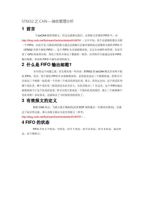
4 FIFO的状态FIFO共有五个状态:空状态,挂号1状态,挂号2状态,挂号3状态,溢出状态。
如下图所示:图1如上图,FIFO的状态是通过两个标志(FMP,FOVR)来体现的,FMP占两个位,用来标志当前报文所存储的邮箱,FOVR用以标志FIFO是否溢出。
这两个标志处于FIFO寄存器(CAN_RFxR x=0..1)中。
4.1 FIFO的状态变化分析由图1可知,在初始化状态时,FIFO是处于空状态的,当接收到一个报文时,这个报文存储到FIFO内部的邮箱中,此时,FIFO的状态变成挂号1状态,如果应用程序取走这个消息,则FIFO恢复空状态。
STM8单片机CAN滤波器的设置
STM8单片机CAN滤波器的设置大家好,我是小舒,今天和大家分享一下CAN滤波器相关的内容,滤波器主要用来设置CAN的接收ID,当CAN总线上所挂接的节点较多,数据量较大的话,对单节点的接收判断可能造成较大的压力、占用较多的资源。
为了解决这个问题,可以通过设置滤波器实现只接收特定ID。
ST系列单片机的滤波器设置非常绕,很容易把自己绕晕了,下面以STM8为例和大家分享一下。
注意,此文需要看多遍。
前言在CAN协议里,报文的标识符不代表节点的地址,而是跟报文的内容相关的。
因此,发送者以广播的形式把报文发送给所有的接收者。
节点在接收报文时,根据标识符的值决定软件是否需要该报文;如果需要,就拷贝到RAM里;如果不需要,报文就被丢弃且无需软件的干预。
为满足这一需求,beCAN为应用程序提供了个可配置的、位宽可变的6个(0-5)过滤器组,用于只接收那些软件需要的报文。
硬件过滤的做法节省了CPU开销,否则就必须由软件进行过滤,从而占用一定的CPU资源。
滤波器设置滤波器设置包括下面几个寄存器:CAN滤波模式寄存器1 (CAN_FMR1)和CAN滤波模式寄存器2(CAN_FMR2)、CAN滤波配置寄存器1 (CAN_FCR1)、CAN滤波配置寄存器2 (CAN_FCR2)和CAN 滤波配置寄存器3 (CAN_FCR3),CAN滤波组i寄存器x (CAN_FiRx) (i = 0 .. 5, x = 1 .. 8)。
滤波模式寄存器用于设置滤波器为标识符列表模式和掩码模式,滤波配置寄存器用于开启或关闭滤波器和滤波器的宽度设置,滤波组用于具体滤波设置。
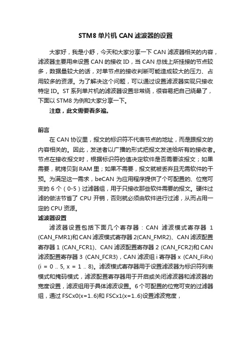
6个可配置的位宽可变的过滤器组,通过FSCx0(x=1..6)和FSCx1(x=1..6)设置滤波宽度,就32位滤波器设置进行解读,CAN报文分为标准帧和扩展帧,标准帧ID11位,扩展帧29位,ID与滤波配置映射关系如上表所示,如滤波模式设置可知可以分为两个ID或者一个ID+Mask。
STM32 CAN过滤器详解

STM32 CAN过滤器详解------SummerRain941. 前言bxCAN是STM32系列最稳定的IP核之一,无论有哪个新型号出来,这个IP核基本未变,可见这个IP核的设计是相当成熟的。
本文所讲述的内容属于这个IP核的一部分,掌握了本文所讲内容,就可以很方便地适用于所有STM32系列中包含bxCAN外设的型号。
有关bxCAN的过滤器部分的内容在参考手册中往往看得“不甚明白“,本文就过滤器的4种工作模式进行详细讲解并使用具体的代码进行演示,这些代码都进行过实测验证通过的,希望能给读者对于bxCAN过滤器有一个清晰的理解。
2. 准备工作2.1. 为什么要过滤器?在这里,我们可以将CAN总线看成一个广播消息通道,上面传输着各种类型的消息,好比报纸,有体育新闻,财经新闻,政治新闻,还有军事新闻,每个人都有自己的喜好,不一定对所有新闻都感兴趣,因此,在看报纸的时候,一般人都是只看自己感兴趣的那类新闻,而过滤掉其他不感兴趣的内容。
那么我们一般是怎么过滤掉那些不感兴趣的内容的呢?下面有两种方法来实现这个目的:第一种方法:每次看报纸时,你都看下每篇文章的标题,如果感兴趣则继续看下去,如果不感兴趣,则忽略掉。
第二种方法:你告诉邮递员,你只对财经新闻感兴趣,请只将财经类报纸送过来,其他的就不要送过来了,就这样,你看到的内容必定是你感兴趣的财经类新闻。
上面那种方法好呢?很明显,第二种方法是最好的,因为你不用自己每次判断哪些新闻内容是你感兴趣的,可以免受“垃圾”新闻干扰,从而可以节省时间忙其他事。
bxCAN的过滤器就是采用上述第二种方法,你只需要设置好你感兴趣的那些CAN报文ID,那么MCU就只能收到这些CAN报文,是从硬件上过滤掉,完全不需要软件参与进来,从而节省了大大节省了MCU的时间,可以更加专注于其他事务,这个就是bxCAN过滤器的意义所在。
2.2.两种过滤模式(列表模式与掩码模式)假设我们是bxCAN这个IP的设计者,现在由我们来设计过滤器,那么我们该如何设计呢?首先我们是不是很快就会想到只要准备好一张表,把我们需要关注的所有CAN报文ID写上去,开始过滤的时候只要对比这张表,如果接收到的报文ID与表上的相符,则通过,如果表上没有,则不通过,这个就是简单的过滤方案。
STM32之CAN---CANID过滤器分析

、八、,刖言在CAN协议里,报文的标识符不代表节点的地址,而是跟报文的内容相关的。
因此,发送者以广播的形式把报文发送给所有的接收者。
节点在接收报文时,根据标识符(CAN ID)的值决定软件是否需要该报文;如果需要,就拷贝到 SRAM里;如果不需要,报文就被丢弃且无需软件的干预。
为满足这一需求,bxCAN为应用程序提供了 14个位宽可变的、可配置的过滤器组(13~0),以便只接收那些软件需要的报文。
硬件过滤的做法节省了CPU开销,否则就必须由软件过滤从而占用一定的CPU开销。
每个过滤器组 x由2个32位寄存器,CAN_FxRO 和CAN_FxR1 组成。
为了让大家了解STM32的bxCAN的接收过滤机制,首先大家需要了解几个概念。
2几个重要的概念2.1过滤器组STM32总共提供14个过滤器组来处理 CAN接收过滤问题,每个过滤器组包含两个 32位寄存器CAN_FxR0和 CAN_FxR1组成,在设置为屏蔽位模式下,其中一个作为标识符寄存器,另一个作为屏蔽码寄存器。
过滤器组中的每个过滤器,编号(叫做过滤器号)从0开始,到某个最大数值(这时最大值并非 13,而是取决于14个过滤器组的模式和位宽的设置,当全部配置为位宽为16,且为标识符列表模式时,最大编号为14*4-1=55 )。
2.2过滤器的过滤模式STM32提供两种过滤模式供用户设置:屏蔽位模式和标识符列表模式。
2.2.1屏蔽位模式为了过滤出一组标识符,应该设置过滤器组工作在屏蔽位模式。
在屏蔽位模式下,标识符寄存器和屏蔽寄存器一起,指定报文标识符的任何一位,应该按照必须匹配”或不用关心”处理。
2.2.2标识符列表模式为了过滤出一个标识符,应该设置过滤器组工作在标识符列表模式。
在标识符列表模式下,屏蔽寄存器也被当作标识符寄存器用。
因此,不是采用一个标识符加一个屏蔽位的方式,而是使用2个标识符寄存器。
接收报文标识符的每一位都必须跟过滤器标识符相同。
2.3过滤器的位宽每个过滤器组的位宽都可以独立配置,以满足应用程序的不同需求。
- 1、下载文档前请自行甄别文档内容的完整性,平台不提供额外的编辑、内容补充、找答案等附加服务。
- 2、"仅部分预览"的文档,不可在线预览部分如存在完整性等问题,可反馈申请退款(可完整预览的文档不适用该条件!)。
- 3、如文档侵犯您的权益,请联系客服反馈,我们会尽快为您处理(人工客服工作时间:9:00-18:30)。
STM8CAN标识符过滤器理解
STM8的CAN有6个过滤器组:
根据配置,每1组过滤器组可以有1个,2个或4个过滤器.
这些过滤器相当于关卡,每当收到一条报文时,CAN要先将收到的报文
从这些过滤器上"过滤"一下,能通过的报文是有效报文,收进FIFO中,
不能通过的是无效报文(不是发给"我"的报文),直接丢弃.
所有的过滤器是并联的,即,一个报文只要通过了一个过滤器,就是算是
有效的.
每组过滤器组有两种工作模式:标识符列表模式,标识符屏蔽位模式.
在标识符列表模式下,收到报文的标识符必须与过滤器的值完全相等,才能通过.
在标识符屏蔽位模式下,可以指定标识符的哪些位为何值时,才能通过.
这其实就是限定了处于某一范围的标识符能够通过.
在一组过滤器中,整组的过滤器都使用同一种工作模式.
另外,每组过滤器中的过滤器宽度是可变的,可以是32、16、8位
由工作模式和宽度,一个过滤器组可以变成以下几中形式之一:
(1)1个32位的屏蔽位模式的过滤器。
2个32位的列表模式的过滤器。
(2)2个16位的屏蔽位模式的过滤器。
4个16位的列表模式的过滤器。
2个16位的列表模式过滤器和1个屏蔽位模式过滤器。
(3)1个16位的屏蔽位模式的过滤器和2个8位屏蔽位模式的过滤器。
2个16位的列表模式的过滤器和2个8位的屏蔽位模式的过滤器。
1个16位的屏蔽位模式的过滤器和4个8位的列表模式的过滤器。
2个16位的列表模式过滤器和4个8位的列表模式的过滤器。
(4)4个8位的屏蔽位模式的过滤器。
4个8位列表模式的过滤器和2个8位的屏蔽位模式的过滤器。
8个8位的列表模式的过滤器。
所有的过滤器是并联的,即,一个报文只要通过了一个过滤器,就是算是有效的.
每组过滤器组有8个8位的寄存器用于存储过滤用的"标准值",分别是CAN_FxRi[i(1...8),x(0...8)]
在32位的屏蔽位模式下:
有1个过滤器,
FxR[5...8]用于指定需要关心哪些位,FxR[1...4]用于指定这些位的标准值
在32位的列表模式下:
有两个过滤器.
FxR[1...4]指定过滤器0的标准值,收到报文的标识符只有跟
FxR[1...4]完全相同时,才算通过.
FxR[5...8]指定过滤器1的标准值.
在16位的屏蔽位模式下:
有2个过滤器.
FxR[1...4]配置过滤器0,其中,[31-16]位指定要关心的位,[15-0]位指定这些位的标准值.
FxR[5...8]配置过滤器1,其中,[31-16]位指定要关心的位,[15-0]位指定这些位的标准值.
在16位的列表模式下:
有4个过滤器.
FxR[1...2]配置过滤器0,FxR[3...4]配置过滤器1
FxR[5...6]配置过滤器2,FxR[7...8]配置过滤器3.
其他模式类似这里我就不一一举例了。
STM8的CAN有1个FIFO,每组过滤器组必须关联这一个FIFO.且复位默认就关联到FIFO.
所谓"关联",是指假如收到的报文从某个过滤器通过了,那么该报文会被存到该过滤器相连的FIFO.
每当收到一个报文,CAN就将这个报文先与FIFO关联的过滤器比较,如
果被匹配,就将此报文放入FIFO中.如果还是不匹配,此报文就被丢弃.
FIFO的所有过滤器都是并联的,只要通过了其中任何一个过滤器,该报文就有效
每个FIFO中只有激活了的过滤器才起作用,换句话说,如果一个FIFO有8个过滤器,但是只激话了3个,
那么比较报文时,只拿这3个过滤器作比较.
一般要用到某个过滤器时,在初始化阶段就直接将它激活.
需要注意的是,FIFO必须至少激活一个过滤器,它才有可能收到报文.如果一个过滤器都没有激活,那么是所有报文都报废的.
一般的,如果不想用复杂的过滤功能,FIFO可以只激活一组过滤器组,且将它设置成32位的屏蔽位模式,
两个标准值寄存器(FxR[1..4],FxR[5..8])都设置成0.这样所有报文均能通过.
STM8CAN中,另一个较难理解的就是过滤器编号.
过滤器编号用于加速CPU对收到报文的处理.
收到一个有效报文时,CAN会将收到的报文,以及它所通过的过滤器编号,一起存入接收邮箱中,
CPU在处理时,可以根据过滤器编号,快速的知道该报文的用途,从而作出处理.
不用过滤器编号其实也是可以的,这时候CPU就要分析所收报文的标
识符,从而知道报文的用途.
由于标识符所含的信息较多,处理起来就慢一点了.
STM8使用以下规则对过滤器编号:
(1)FIFO的过滤器分别独立编号,均从0开始按顺序编号.
(2)所有关联同一个FIFO的过滤器,不管有没有被激活,均统一进行编号.
(3)编号从0开始,按过滤器组的编号从小到大,按顺序排列.
(4)在同一过滤器组内,按寄存器从小到大编号.FxR[1..4]配置的过滤器编号小,FxR[5..8]配置的过滤器编号大.
(6)过滤器编号是有弹性的.当更改了设置时,每个过滤器的编号都会改变.
但是在设置不变的情况下,各个过滤器的编号是相对稳定的.
这样,每个过滤器在自己在FIFO中都有编号.在FIFO_0中,编号从0--(N-1),其中N为它的过滤器总数.一个FIFO如果有很多的过滤器,可能会有一条报文,在几个过滤器上均能通过,这时候,这条报文算是从哪儿过来的呢?
STM8在使用过滤器时,按以下顺序进行过滤
(1)位宽为32位的过滤器,优先级高于位宽为16位的过滤器16位的高于8位
(2)对于位宽相同的过滤器,标识符列表模式的优先级高于屏蔽位模式
(3)位宽和模式都相同的过滤器,优先级由过滤器号决定,过滤器号小的优先级高
按这样的顺序,报文能通过的第一个过滤器,就是该报文的过滤器编号,被存入接收邮箱中。
