固定翼无人机的二阶PID滑模控制方法
控制系统中的滑模控制算法在飞行器中的应用研究

控制系统中的滑模控制算法在飞行器中的应用研究滑模控制算法是一种有效的控制系统设计方法,在飞行器中具有广泛的应用前景。
本文将对控制系统中的滑模控制算法在飞行器中的应用进行研究,并探讨其优势和局限性。
首先,我们将介绍滑模控制算法的基本原理。
滑模控制算法是一种非线性控制方法,其核心思想是通过引入滑模面,将系统的状态引导到滑模面上,从而实现对系统的控制。
滑模控制算法具有快速响应速度、强鲁棒性等特点,适用于快速变化、非线性和不确定性较大的系统。
在飞行器中,滑模控制算法可以应用于多个方面。
首先,滑模控制算法可以用于飞行器的姿态控制。
通过合理选择滑模面和设计控制律,可以实现对飞行器的姿态稳定控制。
这在无人机和飞行器的自动驾驶系统中尤为重要。
其次,滑模控制算法也可以用于飞行器的轨迹跟踪控制。
通过设定期望轨迹,利用滑模控制算法实现飞行器对期望轨迹的精确跟踪。
这在飞行器的航迹控制和路径规划中有重要的应用,可以确保飞行器按照预定的轨迹进行飞行。
此外,滑模控制算法还可以用于飞行器的故障容错控制。
通过使用滑模控制算法,可以实现对系统中的故障进行检测和容错处理。
当系统中发生故障时,滑模控制算法可以迅速调整系统的状态,以保持飞行器的稳定性和安全性。
然而,滑模控制算法也存在一些局限性。
首先,滑模控制算法对系统参数的精确测量和估计要求较高。
若系统参数估计存在误差或未能准确测量,滑模控制算法可能无法达到预期效果。
其次,滑模控制算法在实际系统中可能会引入高频振荡问题,对于某些对控制精度要求较高的飞行器应用来说,这可能是一个挑战。
此外,滑模控制算法的设计和调试也相对较为复杂,需要较高的专业知识和经验。
为了克服这些局限性,研究人员正在进行进一步的改进和优化滑模控制算法。
一种常见的改进方法是将滑模控制算法与其他控制算法相结合,如PID控制算法、模糊控制算法等,以改善系统的性能。
此外,研究人员也在探索使用自适应滑模控制算法来克服系统参数变化的影响,提高系统的鲁棒性和适应性。
无人遥控飞行器稳定性与PID控制方法说明书
AUTONOMOUS QUADCOPTER STABILITYWITH PID CONTROLSri Wahyuni1, M. Izar Bahroni2, Faikul Umam3University of Trunojoyo MaduraMechatronics Department of Engineering FacultyEngineering FacultyBangkalan, East Java, Indonesia1**********************.id,2*******************,3*******************.idAbstract—Unmanned Aerial Vehicle (UAV) has many uses, including aerial photography, aerial mapping and monitoring activities. Quadcopter is a type of UAV that uses four rotors. The speed of each rotor has a considerable influence on the movement. The quadcopter movement can be done in this research, namely the process of arming, taking off, hover, and landing on decisions made by the system (autonomous). How the quadcopter achieves a balance in its movement to be stable and responsive requires a method. One method that is suitable for processing stability is the method (PID). The PID method has three main parameters, namely Proportional (Kp), Integral (Ki), Derivatives (Kd), with the determination of the constant through the trial and error process to obtain the optimal stability value as the purpose of this study. But the load of the quadcopter and the wind tightness around it is very influential to get the quadcopter movement to survive in stable conditions. Through a series of experimental processes carried out to produce the best constant values, at Kp = 1.3, Ki = 0.04, and Kd = 18, where the quadcopter is able to survive for 20 sec at the same relative point from the time of departure. The addition of GPS sensors in advanced research will be able to make this quadcopter move stable with the monitored position.Keywords—UAV; Quadcopter; PID; AutonomousI.I NTRODUCTIONQuadcopter / quadrotor is one type of UAV (Unmanned Aerial Vehicle) which has a manual or automatic control system. The development of this UAV has been used in various aspects. For example in agriculture. The Center for Agricultural Land Resources Research and Development began developing unmanned aircraft with the aim of analyzing the condition of plants / vegetation or agricultural land using VNIR, SWIR, thermal, radar or SAR bands [1]. Another example in the military field, the reconnaissance process in hard-to-reach areas is the background of the development of drones / UAVs by the National Aeronautics and Space Agency (LAPAN) [2].Aerial footage Photographty, Aerial footage Videography, Aerial mapping including activities that require drones / UAVs in the implementation. In addition to the skills of the user users, the stability and the surrounding natural conditions also have a considerable influence. A good drone is a drone / UAV that can maintain stability from outside interference, for example wind speed and frequency interference. Quadcopter is one type of UAV with four rotor drives. Each rotating rotor has a lift force and has the same distance to the center of gravity. This type of quadcopter is one type of drone that is quite easy to maneuver.The method used to be able to adjust the rotational speed of a quadcopter motor is the PID method. The method that uses proportional (Kp), integral (Ki), derivative (Kd) elements aims to accelerate the reaction of a system, eliminate offsets and produce large initial changes.Literatur ReviewResearchers of Gembong ES examined the height control on a quadcopter. In controlling the quadcopter, the PID method was used to obtain stability. Researchers are more likely to do testing in the form of simulations [3]. Likewise with Panca AK researchers, the method used is the Fuzzy PID in stabilizing the height of the quadcopter. This research only focuses on pitch and roll angle movements [4]. Guneshwor Singh menjelaskan tentang navigasi otomatis pada quadcopter.There are two types of propellers in the test. Propellers with a 10 inch size and a pitch of 4.5 can produce a greater total thrust than the use of an 8 inch size propeller with the same pitch size. This also affects flight time which tends to be longer when using a 10 inch propeller [5].Analysis of the stability of diagonal motion has been carried out by Salmaa. The analysis includes the combination of lateral motion and longitudinal motion in a quadcopter. Based on the analysis, the stability of the diagonal motion model is obtained that all diagonal motion models are unstable. Therefore PID control is needed by determining the gain of Kp, Ki, and Kd [6].Determination of the combination of PID constants is very influential on the control of stability of the quadcopter. The PID constant generated from the research conducted by Wili Kumara is Kp = 40, Ki = 40, Kd = 60 for roll motion while Kp = 40, Ki = 60, and Ki = 60 for pitch movement. However, the value of this constant has a fluctuation of 1 ° to (-5 °) slope [7].II.P ID M ETHODThe PID method is a control system consisting of three types of controllers, namely Proportional, Integral andInternational Conference on Science and Technology (ICST 2018)Derivative controllers. PID controller is one of the control methods that is often used in industrial control systems [8]. A. Proportional ControllerThe proportional controller has an output proportional to the magnitude of the error signal (the difference between the desired amount and the actual price). More simply it can be said that proportional controller output is a multiplication between proportional constants with input. Changes to the input signal will immediately cause the system to directly change its output by its constants.B. Integral ControllerThe integral controller functions to produce a system response that has a steady state error (zero steady state error). If a plant does not have an integrator element, the proportional controller will not be able to guarantee the system output with a zero steady state error. The use of an integral controller, the system response can be corrected, which has a zero steady state error.An integral controller has characteristics as well as an integral. The controller output is greatly affected by changes that are proportional to the error value. If the error signal does not change, the output will maintain the state as before the input changes.C. Derivative ControllerIntuitively, the oscillating system response is caused by several things. The dynamic process of a plant causes the response of a plant to not change immediately with a change in the control signal, but requires processing time. This time will make the control system experience delays to correct errors. This requires a controller that can predict errors from a system. Derivative controllers are generally used to speed up the initial response of a system, but do not minimize errors in the steady state. Derivative controller work is only effective in a narrow scope, namely in the transition period. Therefore the derivative controller is never used without any other controller of a system [8].III. BLOCK D IAGRAM S YSTEMThe block diagram in Fig. 1 is a system diagram consisting of several inputs which include the MPY-6050 type GY module in which there is an MPU-6050 sensor. Input in the form of slope data (gyrometer) and acceleration (accelerometer) becomes a reference for quadcopter balancing movements. The output of the system in the form of the speed value converted into a voltage value by ESC will drive a brushless motor that amounts to four. Brushless motor speed will be fully controlled using the PID method calculation. The ESC specification and brushless motor are adjusted to the load of the quadcopter.Input in the form of height sensor / wind pressure is a barometer and receiver from 2.4GHz radio control in the process on a different microcontroller. This section is as a medium for information on the height of the quadcopter when the quadcopter airs. Quadcopter communication with groundstation uses a bluetooth / wireless network module. The ground station receives altitude data from bluetooth to be able to control the 2.4Ghz transmitter radio control and provide information on the current mode status and height data on the personal computer.BMP-85MPU-6050Receiver (Rx)Arduino Nano Arduino Nano ESC 30A (4)Brushless MotorBluetoothPersonal ComputerTransmitterInputProcessOutputGround StationBluetoothFig. 1. Block Diagram SystemIV.F LOWCHARTA. General Flowchart Autonomous SystemIn Fig. 2 and Fig. 3 are general autonomous system flowcharts. Overall testing is done if the constant Kp, Ki, Kd is found to be optimal. This process is the whole process of moving the system on a quadcopter.Start Calibration Connecting ?NoYesCheck Bluetooth ConnectionSwitch ModeConnect PersonalComputerConnecting ?NoYesFig. 2. General flowchart of autonomous systems part 1Two bluetooth (master / slave) auto-pairing, both have ID identifiers, so bluetooth will be connected to bluetooth whose identification ID has been aligned. After the Bluetooth connection process is complete, the next step is to connect the personal computer to the system using a USB cable. Users can choose to use autonomous mode (automatic) or manual mode. When using autonomous mode, the system will run automatically according to the system design that has been made. The command to turn on the brushless motor is done by using a radio control transmitter. In the aeromodeling field, the process is often known as the Arming process. Then Take off is a quadcopter process to take off. Take off is done until it reaches a height of five meters. If the height has reached ten meters, the quadcopter will maintain height and stability for 30 seconds. Then the quadcopter will land / land slowly until it reaches the surface. But if the user uses manual mode. The manual program will be activated, all control systems are carried out manually by the user with a radio control device.Flowchart PID.Height = 10 m ?Arming/Motor ONMotor Off EndNoYes Take Off HoverLandingAutonomous Mode ON.?Start AutonomousProgram Start Manual ProgramYesNoCheck QuadcopterHeightControl by user (Transmitter)Fig. 3. General flowchart of autonomous systems part 2In Fig. 4 is a flowchart from the PID method. The PID method is used to maintain the stability of the quadcopter when moving. This method requires the main constants, Kp, Ki, Kd and Set point. The constant will be used to obtain an optimalsystem response. Determination of the value of Kp, Ki and Kd based on experiments by adjusting specifications on hardware. Starting with the reading of the gyro quadcopter value on the pitch, roll and yaw axis. The gyro data will be used as input for the calculation of the PID method. The output from the PID calculation will produce a PWM value for each brushless motor. The process will repeat the process until the error value is 0. The PID calculation is applied to the manual mode or autonomous mode.StartKp, Kd, Ki, Error, Last Error, SetpointRead MPU-6050 Gyro Value PID calculation Check ErrorError = 0EndYesNoPitch, Roll, Yaw PWM Motor BrushlessPWM motor1 = motor2 = motor3 = motor4Fig. 4. Flowchart PIDV.T ESTINGA.Bluetooth Distance TestingTesting is done in the open. This test aims to determine the range of the second Bluetooth communication. Because bluetooth communication is very important, the installation of the bluetooth module and the direction of the antenna on the bluetooth module must be considered very carefully. shown in Table 1.TABLE I.REACH TESTING DATAbluetooth communication, the average value of the range was 21.5 meters. If the Bluetooth range exceeds the range that has been entered in the test, the data communication will not be sent to the maximum or even thecommunication will be interrupted.B. Testing of Motor Lifting Power (Thrust)Lifting (thrust) testing is carried out on each brushless motor used on a quadcopter. Figure 5 is a graph of testing the lift using a 9540 (9 inch) propeller.Fig. 5. Motor Lift Power ChartC. Testing the PID MethodPID method is the main method used for quadcopter stabilization process. In testing this method, to get proportional (Kp), integral (Ki) and derivative (Kd) constants is done by trial and error. When the system is given a constant Kp, Ki, Kd is observed for quadcopter behavior. Testing the PID method is done in the test box. The test box is shown in Fig. 6.Testing to find a good system response is repeated. By observing the movement of the quadcopter in the stabilization process there will be some differences, including the response of the quadcopter stability to time. Here are some test results using Kp, Ki, Kd that have been done.Fig. 6. Stability TestFig. 7 is a test with a constant value of Kp = 1.3, Ki = 0.04 Kd = 5. The value of this constant is used continuously by the system. In addition to the response to steadystate fast enough, the response is not too visible to perform large oscillations. When testing, 200 sensor reading samples were taken with the assumption of data retrieval for four seconds.Fig. 7. Results of Testing the PID MethodVI. CONCLUSION AND FURTHER RESEARCHBased on the testing and analysis results that have been carried out in the research, the following conclusions are obtained:1. Quadcopter can perform optimal stability movementsusing the PID method. With a constant value of Kp = 1.3, Ki = 0.04 and Kd = 18.2. Delivery of altitude data sent via bluetooth communicationcan work well up to a distance of 21.5 meters.3. The initial position of the quadcopter during take off willaffect the shift of movement during flight.4.The type of propeller 1045 has a fairly large lift, but thetemperature of the motor when used is faster heat.5. The type of propeller 9450 tends to be more stable inmovement.6. Quadcopter tends to stay away from the initial coordinatepoint if the flight time is increased.From the results of the research conducted, for the next development, it is suggested that the following:1. Pay attention to the specifications of the quadcopter partused, especially in the specifications of the motor for lift strength and propeller type.munication for quadcopter and ground station shoulduse telemetry. So that the data transmission range can be carried out with a considerable distance and minimize frequency interference from outside.3.Adding GPS components, to determine the position /location when flying.4.Provides an electronic shock damper component that is inthe quadcopter to minimize the vibration generated by the four brushless rotors.5.Better mechanical design, to make it easier to implementthe control algorithm used.6.Pay attention to security factors during implementation.Addition of propeller protectors so that the propeller is safe when experiencing a system experiencing errors / crashes.7.When testing, you must first consider the state of the windspeed, this is to reduce the potential of the quadcopter carried by the wind (flyaway).A CKNOWLEDGMENTWe would like to show our gratitude to all our college and student in Mechatronics Department for sharing their wisdom during our research. This research was supported by Basic Mechatronic Laboratory.R EFERENCES[1]R. Shofiyanti, “Teknologi Pesawat Tanpa Awak untuk Pemetaan danPemantau an Tanaman dan Lahan Pertanian”, Informatika Pertanian, Vol.20, No.2, pp 58-64, 2011.[2]Aerostar TUAV : Drone Intai Andalan Skadron Udara 51 TNI AU.</aerostar-tuav-drone-intai-andalan-skadron udara-51-tni-au/> accessed on September 12th 2017.[3]G.E. Setyawan, E. Setiawan, W. Kurniawan, “Sistem KendaliKetinggian Quadcopter Menggunakan PID,” JT IIK, vol 2, no 2, pp 125-131, 2015.[4]P.A. Kusuma, A. Dharmawan, April, “Pengendalian KestabilanKetinggian pada Penerbangan Quadrotor dengan Metode PID Fuzzy,”IJE IS, Vol.7, No.1, pp 61-70, 2017.[5]I.O.G. Singh, “ Self-Navigating Quadcopter,” Int. J. Computer Sci. andInformation Technologies (IJCSIT), vol 6(3), pp 2761-2765, 2015.[6]Salmaa, “Analisa Kestabilan Gerak Diagonal pada Quadrotormenggunakan Kontrol PID,” Jurnal Ilmiah Matematika (MATH unesa), vol 3, no 6, 2017.[7]W.K. Juang, and L.L. Tung, “Pembuatan Mode l Quadcopter yang DapatMempertahankan Ketinggian Tertentu,” Jurnal Teknik Elektro, vol 9, no 2, 2016.[8]W.K. Juang, and L.L. Tung, “Pembuatan Mode l Quadcopter yang DapatMempertahankan Ketinggian Tertentu,” Jurnal Teknik Elektro, vol 9, no 2, 2016.。
基于四旋翼无人机的二阶PD积分滑模控制算法研究
(7)
其中, ξc是加速度控制信号,即:
ξc = ξT + kd (ξT − ξ) + k p (ξT
二阶PD控制器控制参数。 由式(1)~式(6),推导得到控制信号加速度矢量与
控制律u1的关系如下:
图2 控制器结构图 【34】 第40卷 第3期 2018-03
由于 为:
,则上式变 (9)
由式(9)可得:
则: (10)
由式(8)可得: (11)
为了防止式(11)左边值超出[-1,+1],而造成 θc 不存
在,用分段取值的思想来解决这个问题:令 。
(12)
其中,如果俯仰角θ大于 π ,极有可能出现坠机的
2
现象。因此取θ临界值为 π 。
2
结合式(2)、式(5)、式(8)、式(10)、式(12),可以推 导得到外环控制律u1:
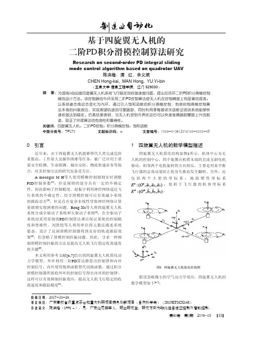
四旋翼无人机简化结构如图1所示,机体中心为无 人机的控制中心,四个旋翼由机臂末端的直流无刷电机 驱动,相邻两个电机旋转的方向相反,主要是用来平衡 飞行器的总角动量防止机身失衡而发生翻转。另外,还 包括两个主要的坐标系:地面惯性坐标系
;依附于飞行器的机体坐标系 。
图1 四旋翼无人机简化结构图
假设忽略微小的空气动力学效应,四旋翼无人机的 数学模型如下[6,7]:
基于四旋翼无人机的
二阶PD积分滑模控制算法研究
Research on second-order PD integral sliding
mode control algorithm based on quadrotor UAV
陈洪楷,满 红,余义斌
CHEN Hong-kai, MAN Hong, YU Yi-bin
无人机线性控制系统PID控制算法

无人机线性控制系统PID控制算法PID线性控制比例微分积分线性控制,即PID线性控制理论,是经典控制理论中线性控制系统甚至一些非线性控制系统中最常见的控制方法。
PID控制系统具有简单,实用,响应快,适应性强等特点,对于被控制对象,往往不需要了解控制模型和响应模型等具体的被控规律,仅使用系统输出的反馈来实现精确控制的规律,因为它的控制与人工手动控制的规律相同。
什么是PID?它分成三个部分,P代表比例控制,I代表积分控制,D代表微分控制。
PID控制器的出现甚至早于经典控制理论的发展。
现代控制理论是建立在状态空间基础上的模型控制理论,在现代控制理论中,对控制系统的分析和设计主要通过对系统的状态建模和状态的描述来进行,因此现代控制理论所采用的控制方法都是应用于各不相同的具体的控制对象,能够更为精确精准的对不同的系统进行定制化设计。
PID控制器的问题:与现代控制理论相比,它们是两种完全不同的控制方法。
PID是控制领域的三种对时间域的三维元素(当前,历史和未来),将三者优化组合在一起完成控制目标,而现代控制则是基于针对某种优化指标,通过设计算法来实现控制的目标PID控制器的最大问题是没有一个明确的系统函数及优化准则,因此PID控制器的调参只能通过经验测试调整,并且它只能将系统调整到某种可接受的近似状态,且并不确定是否能调整到有更优的控制器。
与现代控制理论相比,它们是两种完全不同的控制方法。
PID是控制领域的三种对时间域的三维元素(当前,历史和未来),将三者优化组合在一起完成控制目标,而现代控制则是基于针对某种优化指标,通过设计算法来实现控制的目标。
比例控制当操作人员控制一个系统要求系统的输出达到某个值时给予一定的输入值,输出值逐渐接近直到达到指定的输出值,这个过程中输出值与指定输出值之间的差可以作为输入值的参考控制量,并进行一定的比例调整,这种调整成为比例控制。
例如操作人员手动控制加热器的温度,加热器带有温度传感器作为输出值的表真,在控制过程中,操作人员可以通过视觉直接读取温度传感器的反馈量,并与给定值的比较计算误差,然后通过旋钮操控控制输入量调节加热器的电源输入,使得温度接近并保持给定值的附近。
无人机飞行中的姿态控制技巧

无人机飞行中的姿态控制技巧在无人机飞行中,姿态控制技巧发挥着至关重要的作用。
姿态控制技巧可以使无人机在飞行过程中保持稳定的姿态,提高飞行的精度和安全性。
本文将介绍几种常用的无人机姿态控制技巧。
一、PID控制器PID(比例、积分、微分)控制器是一种经典的姿态控制技巧。
它通过不断调节控制输出以使无人机保持期望的姿态。
PID控制器根据当前姿态误差的大小来计算控制输出。
其中,比例项(P项)根据当前误差计算比例输出,积分项(I项)根据误差的积累计算积分输出,微分项(D项)根据误差变化率计算微分输出。
将三者相加得到PID输出,并作为控制指令施加给无人机。
二、模型预测控制(MPC)模型预测控制是一种基于无人机动力学模型的姿态控制技巧。
它通过预测未来一段时间内的无人机姿态,根据预测结果计算控制指令。
模型预测控制可以有效处理系统的非线性和时变性。
它使用数学模型来描述无人机的动力学行为,并根据模型进行预测和优化,从而实现精确的姿态控制。
三、自适应控制自适应控制是一种能够自我调节参数以适应外部环境和系统变化的姿态控制技巧。
在无人机飞行中,环境条件和飞行状态可能会发生变化,因此对于姿态控制器的参数也需要进行相应的调整。
自适应控制技巧可以根据系统的状态和性能指标来自动调整控制器的参数,从而提高飞行的稳定性和安全性。
四、滑模控制滑模控制是一种常用的鲁棒控制技巧,适用于具有不确定性和扰动的系统。
在无人机姿态控制中,滑模控制可以消除系统的干扰和外部扰动,使无人机能够保持稳定的姿态。
滑模控制技巧通过引入滑模面和滑模控制律来实现对无人机姿态的控制,从而提高飞行的精度和稳定性。
五、模糊控制模糊控制是一种基于模糊逻辑的控制技巧,可以用于处理系统模型不确定或难以建模的情况。
在无人机姿态控制中,模糊控制可以根据事先定义好的模糊规则和知识库来计算控制输出,从而实现对无人机姿态的控制。
模糊控制技巧可以应对复杂和非线性的控制问题,提高无人机的飞行性能和稳定性。
无人机飞行控制中的PID算法研究

无人机飞行控制中的PID算法研究一、绪论无人机技术近年来快速发展,已经广泛应用于军事、民用、娱乐等领域。
无人机的飞行控制技术起着至关重要的作用,其中PID算法是一种经典的飞行控制算法。
本文将对无人机飞行控制中PID算法的研究进行探讨。
二、PID算法概述PID算法是由比例控制、积分控制和微分控制三个部分组成的一种自适应控制算法。
其中比例控制、积分控制和微分控制分别对应着误差、误差积分和误差微分。
PID算法将这三个部分加权相加,得到控制量。
其中比例控制作用于瞬时误差,积分控制作用于系统稳态误差,微分控制作用于系统动态响应。
PID控制算法实现过程中,需要将目标量与实际量进行比较,计算误差,然后对误差进行处理。
比例项的作用是将误差与控制量成比例,积分项的作用是将误差的积分量与控制量成比例,微分项的作用是将误差的微分量与控制量成比例。
三个项进行加权,得到最终控制量,通过控制量调整系统,使其逐渐达到稳定状态。
三、PID算法在无人机飞行控制中的应用PID算法广泛应用于无人机的飞行姿态控制、高度控制、速度控制等方面。
1. 飞行姿态控制在飞行姿态控制中,通常采用向量旋转方法进行数学建模。
通过将姿态角度变换成三个互相垂直的方向上的角度,然后对每个方向的控制量分别进行PID调节,达到控制飞机旋转的目的。
2. 高度控制高度控制是无人机飞行控制的一个重要方面,通常采用气压传感器来测量无人机所在高度。
在高度控制中,需要将目标高度转换为控制量,通过PID算法调节控制量使无人机上升或下降,从而控制飞机的高度。
3. 速度控制速度控制通常通过GPS获取目标速度,通过对速度差进行PID 调节,使无人机达到目标速度。
四、PID算法的优缺点PID算法具有稳定性好、响应速度快、运算量小等优点。
但是PID算法具有固有的局限性,比如不能有效处理非线性系统、误差积分会导致系统欠阻尼等。
五、结论PID算法是无人机飞行控制中最为经典的控制算法之一,在无人机的飞行姿态控制、高度控制、速度控制中应用广泛。
PID调参——无人机飞行器
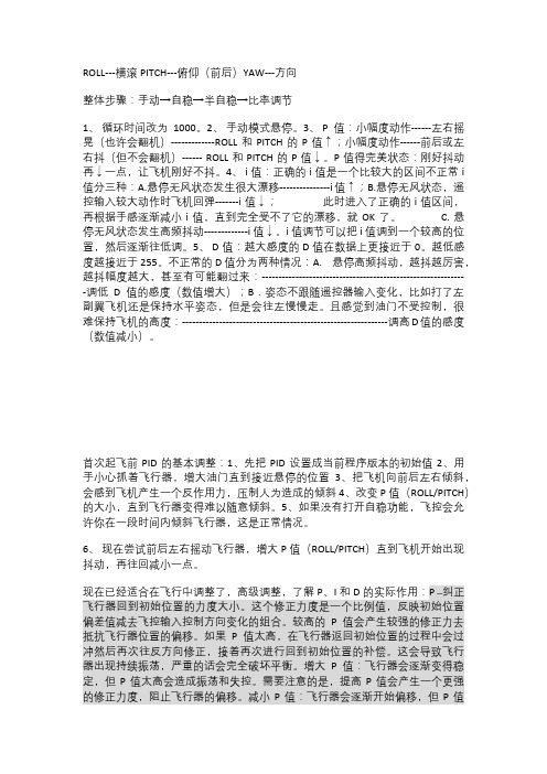
ROLL---横滚PITCH---俯仰(前后)YAW---方向整体步骤:手动→自稳→半自稳→比率调节1、循环时间改为1000。
2、手动模式悬停。
3、 P值:小幅度动作------左右摇晃(也许会翻机)-------------ROLL和PITCH的P值↑;小幅度动作------前后或左右抖(但不会翻机)------ ROLL和PITCH的P值↓。
P值得完美状态:刚好抖动再↓一点,让飞机刚好不抖。
4、 i值:正确的i值是一个比较大的区间不正常i 值分三种:A.悬停无风状态发生很大漂移---------------i值↑;B.悬停无风状态,遥控输入较大动作时飞机回弹-------i值↓;此时进入了正确的i值区间,再根据手感逐渐减小i值,直到完全受不了它的漂移,就OK了。
C. 悬停无风状态发生高频抖动-------------i值↓。
i值调节可以把i值调到一个较高的位置,然后逐渐往低调。
5、 D值:越大感度的D值在数据上更接近于0。
越低感度越接近于255。
不正常的D值分为两种情况:A. 悬停高频抖动,越抖越厉害,越抖幅度越大,甚至有可能翻过来:-------------------------------------------------------------调低D值的感度(数值增大);B.姿态不跟随遥控器输入变化,比如打了左副翼飞机还是保持水平姿态,但是会往左慢慢走。
且感觉到油门不受控制,很难保持飞机的高度:-------------------------------------------------------------调高D值的感度(数值减小)。
首次起飞前PID的基本调整:1、先把PID设置成当前程序版本的初始值2、用手小心抓着飞行器,增大油门直到接近悬停的位置3、把飞机向前后左右倾斜,会感到飞机产生一个反作用力,压制人为造成的倾斜4、改变P值(ROLL/PITCH)的大小,直到飞行器变得难以随意倾斜。
基于PID与滑模控制的四旋翼姿态控制_仿真与实验
基于PID与滑模控制的四旋翼姿态控制_仿真与实验基于PID与滑模控制的四旋翼姿态控制:仿真与实验摘要:四旋翼无人机作为一种具有广泛应用前景的飞行器,其姿态控制技术一直备受关注。
本文基于PID与滑模控制方法,针对四旋翼的姿态控制问题进行了研究。
首先,建立了四旋翼的动力学模型,并设计了PID控制器用于姿态控制。
然后,引入滑模控制方法,通过设计滑模面和控制律,实现了对四旋翼的姿态控制。
最后,通过仿真和实验验证了所提出方法的有效性。
引言:随着无人机技术的发展,四旋翼无人机作为一种灵活、机动性强的飞行器,被广泛应用于农业、航拍、物流等领域。
然而,四旋翼无人机在实际飞行中容易受到外界干扰而导致姿态失控,因此姿态控制技术显得尤为重要。
方法:本文采用了PID与滑模控制相结合的方法实现四旋翼的姿态控制。
首先,建立了四旋翼的动力学模型,包括俯仰角、横滚角和偏航角。
然后,设计了PID控制器,通过对误差的比例、积分和微分进行调节,实现了对四旋翼的姿态控制。
接着,引入滑模控制方法,通过设计滑模面和控制律,使系统能够在有限时间内从初始状态滑到滑模面上,进而实现对四旋翼的姿态控制。
结果:通过仿真实验和实际飞行实验,验证了所提出方法的有效性。
仿真实验结果表明,PID与滑模控制相结合的方法能够实现对四旋翼的姿态控制,并具有较好的性能指标。
实际飞行实验结果进一步证明了所提出方法的可行性和实用性。
结论:本文基于PID与滑模控制方法,研究了四旋翼的姿态控制问题,并通过仿真和实验验证了所提出方法的有效性。
结果表明,PID与滑模控制相结合的方法能够实现对四旋翼的姿态控制,并具有较好的控制性能。
未来的研究可以进一步优化控制器参数,提高四旋翼的姿态控制性能。
此外,还可以考虑引入其他控制方法,如模糊控制、自适应控制等,进一步提高四旋翼的飞行性能和安全性。
飞行器控制科技中的PID控制器使用方法

飞行器控制科技中的PID控制器使用方法飞行器是一种高度复杂的系统,它需要通过精确的控制来保持平衡、稳定和精确的飞行。
PID(比例-积分-微分)控制器是一种常用的控制方法,被广泛应用于飞行器控制科技中。
在本文中,我们将讨论PID控制器的使用方法以及在飞行器控制中的应用。
首先,让我们了解什么是PID控制器。
PID控制器是一种经典的反馈控制方法,它根据当前误差的大小来调整输出。
它由三个部分组成:比例(P),积分(I)和微分(D)。
比例控制作用于当前误差,将其乘以一个系数Kp,用于调整输出。
积分控制作用于误差的累积值,将其乘以一个系数Ki,并累积到输出中,以消除系统的静态误差。
微分控制作用于误差的变化率,将其乘以一个系数Kd,并添加到输出中,以对系统进行稳定性控制。
在飞行器控制中,PID控制器常用于姿态控制(例如飞行器的俯仰、横滚和偏航)以及高度控制。
下面,我们将分别探讨这两个方面的应用。
在飞行器的姿态控制中,PID控制器可以用于控制飞行器的角度或角速度。
首先,我们需要将目标角度或角速度与当前实际测量值进行比较,计算误差。
然后,根据PID控制器的算法,计算输出。
比例部分根据误差的大小来调整输出,积分部分消除静态误差,而微分部分增强控制系统的稳定性。
通过不断调整PID控制器的系数Kp,Ki和Kd,我们可以实现更快速且更可靠的姿态控制。
在高度控制方面,PID控制器用于控制飞行器的爬升率或下降率。
同样地,我们需要将目标高度与当前的高度测量值进行比较,计算误差。
然后,通过PID控制器的计算,调整输出。
比例部分根据误差的大小进行调整,积分部分消除静态误差,微分部分增强系统的稳定性。
通过调整PID控制器的系数,我们可以实现稳定和精确的高度控制。
在使用PID控制器时,我们需要根据实际情况进行参数调整。
参数调整的目标是使飞行器响应速度快、稳定性好且能够抵抗外界干扰。
常用的参数调整方法包括手动调整和自动调整。
手动调整方法是基于经验和试错的,飞行员或工程师通过观察飞行器的响应特性来调整PID控制器的系数。
飞翼布局无人机二阶滑模姿态跟踪鲁棒控制
内收敛到滑模流形 s = = 0上 , 基于此二阶滑模算法 设计 的 自适应 s u p e r t w i s t i n g二 阶 滑模 干 扰 观 测 器 ,
将符 号 函数 隐藏 在 积 分项 里 , 得 到 连续 的干 扰 补 偿 值, 避免了抖振造成控制系统的不稳定。
飞 翼 布 局 无 人机 二 阶滑 模 姿 态 跟 踪 鲁棒 控 制
谭 健 , 周 洲 , 祝 小平 , 许 晓 平
, 1 . 西北工业 大学 无人机特种技术重点 实验室 , 陕西 西 安
\ 2 . 西北工业大学 无人机研究所, 陕西 西布局无人机 受扰姿 态控制 问题 , 提 出一种二 阶滑模姿 态跟 踪鲁棒控 制 方案 。基 于时
2 0 1 5年 4月
西 北 工 业 大 学 学 报
J o u r n a l o f No r t h we s t e r n P o l y t e c h n i c a l U n i v e r s i t y
Ap r . 201 5
第3 3卷第 2 期
V0 1 . 3 3 No . 2
面附加 力 的 问题 , 采 用非 线 性控 制分 配 , 按 照 阻力 最 小 的优 化 目标 将 控 制 力矩 分 配 到舵 面 上 。最 后 , 仿
真结果验证 了所提 出的方法具有 良好 的控制性能。
为保证 飞行控制 的性能 , 采用干扰观测器估计
收 稿 日期 : 2 0 1 4 ・ 0 9 - 2 8 基金项 目: 国家 自然科 学基 金( 1 1 3 0 2 1 7 8 ) 资助
基 于 以上 分 析 , 本 文 提 出一 种 二 阶滑模 姿态 跟
无人机pid控制原理

无人机pid控制原理今天咱们来唠唠无人机的PID控制原理,这可是个特别好玩的事儿呢。
咱先来说说啥是PID。
P呢,就是比例(Proportional)。
你可以把它想象成一个特别直接的小助手。
比如说,无人机想要保持在某个高度,结果它发现自己比目标高度低了一些。
这个P就会根据这个高度差,直接给一个控制信号,就好像在说:“低了这么多,那我就按照这个低的程度给个力,让你往上飞一点。
”如果高度差大,那这个控制信号就大;高度差小,控制信号就小。
就像你走路,离目的地远就大步走,近了就小步挪挪就好啦。
然后就是I,积分(Integral)。
这个I呀,就像是一个有耐心的记录员。
它会把之前所有的误差都积累起来。
比如说,无人机在飞行过程中,一直有一点小的高度偏差,可能每次P调整了,但是还是有那么一点点没调好。
这时候I就出马了,它会把之前这些小偏差加起来,然后根据这个总和再给一个控制信号。
就好比你每次考试都差一点点满分,把这些小差距加起来,到后面就知道要怎么更努力啦。
I的作用就是为了消除那些一直存在的小误差,让无人机的飞行更加精准。
再来说说D,微分(Derivative)。
D就像是一个预测小能手。
它会看这个误差的变化速度。
比如说,无人机本来在稳定高度飞行,突然一阵风把它往下吹得很快,这个时候高度误差的变化速度就很大。
D就会根据这个变化速度,给出一个控制信号,让无人机快速反应。
就像你在滑滑梯,突然滑得特别快,你得赶紧做点什么来稳住自己一样。
D就是这样,它能够让无人机在遇到突发情况的时候,快速调整自己的状态。
这三个部分啊,就像一个超级组合。
P是快速反应的前锋,I是耐心细致的中场组织者,D是机智的后卫。
它们三个一起合作,才能让无人机飞得稳稳当当的。
你看啊,当无人机起飞的时候,这三个家伙就开始忙乎起来了。
比如说要控制无人机的俯仰角,刚开始起飞的时候,P就根据目标俯仰角和当前俯仰角的差值,给出一个初步的控制指令,让电机调整转速。
但是可能因为各种干扰,这个差值还在,I 就把之前的这些差值都积累起来,给一个补充的控制信号。
基于滑模控制的无人机姿态稳定控制研究

基于滑模控制的无人机姿态稳定控制研究无人机在现代航空领域扮演着越来越重要的角色。
然而,无人机姿态的稳定控制一直是一个挑战性的问题。
为了解决这个问题,研究人员一直在不断探索各种姿态控制方法。
其中,基于滑模控制的无人机姿态稳定控制研究成为了一个热门方向。
本文将对基于滑模控制的无人机姿态稳定控制方法进行深入研究和探讨。
无人机姿态稳定控制的目标是实现无人机在飞行过程中的稳定姿态,以提高飞行性能和控制精度。
为了实现这个目标,滑模控制被广泛应用于无人机姿态控制系统中。
滑模控制是一种非线性控制方法,具有强鲁棒性和抗干扰能力,能够有效地应对无人机飞行过程中的不确定性和外部干扰。
基于滑模控制的无人机姿态稳定控制方法主要分为两个方面:滑模控制律的设计和滑模观测器的设计。
滑模控制律的设计是指根据无人机的动力学模型和控制要求,设计一个具有理想响应特性的滑模控制器。
滑模观测器的设计是指利用观测器来估计无人机的状态,以实现对滑模控制器的反馈。
在滑模控制律的设计中,经典的滑模控制器可以分为两个部分:滑模面和控制律。
滑模面是指通过引入一个额外的自适应参数,使得无人机系统在滑动模式下达到稳定。
控制律是指根据滑模面和系统状态,计算出控制输入,以实现对无人机系统的稳定控制。
在滑模观测器的设计中,一般采用延迟观测器或者自适应观测器来估计无人机的状态。
为了实现基于滑模控制的无人机姿态稳定控制,需要首先建立无人机的动力学模型。
无人机的动力学模型一般基于欧拉角参数化,包括飞行器的姿态角和角速度。
然后,根据无人机动力学模型和控制要求,设计滑模控制器的滑模面和控制律。
滑模面的设计可以利用随时间改变的函数来实现。
控制律可以采用线性定常控制或非线性反馈控制来实现。
接下来,设计一个滑模观测器来估计无人机的状态。
滑模观测器可以通过估计无人机的输出误差和系统状态,来实现对滑模控制器的反馈。
在进行基于滑模控制的无人机姿态稳定控制研究时,需要考虑以下几个方面。
飞翼布局无人机二阶滑模姿态跟踪鲁棒控制

飞翼布局无人机二阶滑模姿态跟踪鲁棒控制谭健;周洲;祝小平;许晓平【期刊名称】《西北工业大学学报》【年(卷),期】2015(000)002【摘要】针对飞翼布局无人机受扰姿态控制问题,提出一种二阶滑模姿态跟踪鲁棒控制方案。
基于时标分离特性,将飞翼布局无人机姿态控制系统分为内外回路进行设计。
外回路采用自适应二阶终端滑模控制器,利用自适应算法调节切换增益抑制复合干扰对系统性能的影响,同时二阶终端滑模将不连续的符号函数加在控制量的导数上,通过积分得到连续的滑模控制律,从而有效地消除了常规滑模控制器的抖振。
内回路采用基于自适应super twisting滑模观测器的积分滑模控制器,设计自适应super twisting滑模观测器以实现对内回路复合干扰的估计和补偿。
最后通过控制分配环节将控制力矩分配到舵面上,仿真结果验证了所提方案的有效性。
【总页数】6页(P185-190)【作者】谭健;周洲;祝小平;许晓平【作者单位】西北工业大学无人机特种技术重点实验室,陕西西安 710072;西北工业大学无人机特种技术重点实验室,陕西西安 710072;西北工业大学无人机研究所,陕西西安 710072;西北工业大学无人机特种技术重点实验室,陕西西安710072【正文语种】中文【中图分类】TP273【相关文献】1.飞翼布局无人机反步L2增益纵向着陆鲁棒控制 [J], 谭健;周洲;祝小平;许晓平2.鲁棒控制在飞翼无人机控制律设计中的应用 [J], 葛志闪;周洲;王睿3.飞翼布局舰载无人机自主着舰技术研究 [J], 刘慧英; 田征戈; 张笑宇; 郭慧娟4.飞翼布局无人机控制律设计 [J], 张羽白;肖成方;邹俊俊;翁雪花5.典型场景下飞翼布局无人机综合隐身能力分析 [J], 刘文俭;熊家军;何松;范亚因版权原因,仅展示原文概要,查看原文内容请购买。
飞行器滑模控制设计及其实现
飞行器滑模控制设计及其实现一、引言飞行器控制是实现其飞行性能的关键,而滑模控制是一种有效的控制方式。
本文将介绍飞行器滑模控制的基本原理及设计流程,并通过算法实现该控制方式。
二、滑模控制介绍滑模控制是一种非线性控制方式,它通过在控制系统中引入一个滑动模式来实现鲁棒性和饱和性控制。
滑模控制的主要特点是可以对包括非线性和时变系统在内的多种系统实现控制。
三、滑模控制设计流程1、系统建模首先需要进行系统建模,将飞行器建模成数学模型。
根据所研究的对象和控制目标,可以选择适当的动力学方程来描述其状态。
2、确定控制目标和控制要求在设立控制目标后,需要细化控制要求,确定具体的调节参数和目标轨迹等,以实现控制目标。
3、滑动模式设计根据控制目标和控制要求,选择相应的滑模函数,并对其进行设计。
可以选用一些经典的滑模函数(如单纯平面滑模函数、超越函数等),并对其进行参数设计,以实现系统的鲁棒性和饱和性控制。
4、控制器设计在确定了滑动模式和其参数后,需要进行滑模控制器的设计。
可以采用传统的滑模控制器(如二阶滑模控制器、变结构滑模控制器等),或者是非线性滑模控制器(如自适应滑模控制器、鲁棒非线性滑模控制器等)。
5、模型仿真和实验验证在设计好的滑模控制器基础上,进行模型仿真和实验验证,以评估控制效果。
四、滑模控制实现在MATLAB/Simulink平台下,通过编写对应的代码,完成基于滑模控制的飞行器控制,并进行模拟运行。
实验结果表明,滑模控制效果良好,在实际飞行控制中有着广泛的应用前景。
五、总结本文介绍了飞行器滑模控制的基本原理、设计流程和实现方法,以及滑模控制在飞行器控制中的应用前景和发展方向。
在飞行器控制领域,滑模控制具有很高的实用性和发展潜力,值得深入研究和推广应用。
滑模控制 二阶倒立摆 matlab
滑模控制二阶倒立摆 matlab滑模控制是一种常用的控制方法,在控制二阶倒立摆中也可以得到很好的应用。
通过加入滑模控制器可以提高控制系统的稳定性和鲁棒性。
在 Matlab 中,可以使用 Simulink 来进行二阶倒立摆的仿真和控制器设计。
具体步骤如下:1. 搭建二阶倒立摆的模型,包括小车、摆杆和配重块等组成部分。
2. 设计 PID 控制器,作为基准控制器用于比较滑模控制器的性能;3. 按照滑模控制器设计的思路,搭建滑模控制器模型,其中包括滑模面、滑模控制律等组成部分。
4. 将滑模控制器与二阶倒立摆模型进行连接,并进行仿真。
实现过程中的代码如下:1. 建立模型:使用 Simulink 中的组件、信号源、仿真器等构建二阶倒立摆控制系统模型。
2. PID 控制器设计:```matlabKp = 1.5;Ki = 0.01;Kd = 0.2;pid_controller = pid(Kp, Ki, Kd);```3. 滑模控制器设计:```matlabs = 0.1;r = 0.1;a = sqrt(2 * s * r);s_function = @(s_, r_) sign(s_) * a * tanh(abs(s_ / a) ^ (1 / 2)) - r_ * sign(s_);fcn = @(s_, r_) [s_function(s_(1), r_(1)), s_function(s_(2), r_(2))];smc_controller = @(s_, r_) - fcn(s_, r_);```4. 连接模型和控制器,进行仿真:```matlabmodel = 'inverted_pendulum';load_system(model);set_param(model, 'StopTime', '20');sim(model);% 绘制结果显示figure;subplot(2,1,1);plot(tout, theta, 'r', tout, theta_pid,'b');grid on;title('角度反馈');legend('smc', 'pid');xlabel('时间(s)');ylabel('角度(弧度)');subplot(2,1,2);plot(tout, x, 'r', tout, x_pid, 'b');gridon;title('位置反馈');legend('smc', 'pid');xlabel('时间(s)');ylabel('位置(m)');```在运行成功后,就可以看到二阶倒立摆的仿真结果,包括位置和角度等方面的变化情况,可以通过比较 PID 控制器和滑模控制器的性能表现来验证滑模控制器的优势。
固定翼无人机自适应滑模控制

固定翼无人机自适应滑模控制宗群;张睿隆;董琦;张超凡【期刊名称】《哈尔滨工业大学学报》【年(卷),期】2018(050)009【摘要】针对固定翼无人机的姿态和速度控制中存在不确定和外部扰动的问题,设计自适应超螺旋滑模干扰观测器和控制器,实现了固定翼无人机对速度指令和姿态指令的有限时间精确跟踪.首先建立固定翼无人机速度模型和基于四元数的姿态误差模型;进而在该模型的基础上针对无人机飞行过程中的外部扰动和不确定问题,采用自适应超螺旋滑模算法设计干扰观测器对干扰和不确定进行快速估计,并在此基础上设计多变量超螺旋控制器使固定翼无人机快速、精确地跟踪期望的速度和姿态指令;最后基于Lyapunov理论证明了该系统的稳定性.仿真结果表明:所提出的综合控制策略可以实现固定翼无人机速度与姿态的快速精确跟踪并具有良好的鲁棒自适应能力,而且针对无人机不同的飞行指令,使用该控制策略都能使无人机快速稳定的达到预期目标.【总页数】9页(P147-155)【作者】宗群;张睿隆;董琦;张超凡【作者单位】天津大学电气自动化与信息工程学院,天津300072;天津大学电气自动化与信息工程学院,天津300072;天津大学电气自动化与信息工程学院,天津300072;中国电子科技集团公司电子科学研究院,北京100041;天津大学电气自动化与信息工程学院,天津300072【正文语种】中文【中图分类】TP273【相关文献】1.固定翼无人机倾斜摄影在1:500地形图测绘中的应用 [J], 赵立根;姜霞2.微型固定翼无人机机电性能测试研究 [J], 郑楠3.一种小型固定翼无人机弹射系统的设计 [J], 李国利;王瀚;胡晓航;钟艳4.基于固定翼无人机的航空影像获取方法 [J], 刘辉5.涵道式垂直起降固定翼无人机过渡走廊研究 [J], 王春阳;周洲因版权原因,仅展示原文概要,查看原文内容请购买。
- 1、下载文档前请自行甄别文档内容的完整性,平台不提供额外的编辑、内容补充、找答案等附加服务。
- 2、"仅部分预览"的文档,不可在线预览部分如存在完整性等问题,可反馈申请退款(可完整预览的文档不适用该条件!)。
- 3、如文档侵犯您的权益,请联系客服反馈,我们会尽快为您处理(人工客服工作时间:9:00-18:30)。
ABSTRACT: Considering the influence of system parameter perturbation and external disturbance on the performance of fixed - wing UAV system,the attitude tracking and flying speed tracking of fixed - wing UAV were studied. First, a nonlinear disturbance observer was introduced to accurately estimate the composite interference. Then,on the basis of the disturbance observer,an adaptive second - order PID sliding mode controller was designed to hide the discontinuous sign function on the first derivative of the control volume and obtain the continuous actual control input through integration The chattering caused by the switching control action was eliminated,and the stability of the closed - loop system was proved through the Lyapunov stability theory. The simulation results show that the proposed control scheme can guarantee the accuracy of UAV attitude angle and flight velocity control,and has good robustness to parameter uncertainties and external disturbances. KEYWORDS: External interference; Fixed - wing UAV; System performance; Disturbance observer; Control accuracy
第 36 卷 第 4 期 文章编号: 1006 - 9348( 2019) 04 - 0039 - 05
计算机仿真
2019 年 4 月
固定翼无人机的二阶 PID 滑模控制方法
王 力1 ,祁浩然2 ,穆东旭2 ,张晓蕾3
( 1. 中国民航大学通用航空学院,天津 300300; 2. 中国民航大学电子信息与自动化学院,天津 300300; 3. 中国南方航空股份有限公司湖北分公司飞机维修厂,湖北 武汉 430302)
1 引言
固定翼无人机在空中作业过程中飞行环境会大范围变 化,飞行条 件 甚 至 会 很 恶 劣。条 件 变 化 带 来 的 气 动 参 数 摄 动、建模误差 以 及 外 界 干 扰 都 有 可 能 引 起 飞 行 系 统 的 不 稳
基金项目: 国家自然科学基金项目( u1733119) ; 国家自然科学基金项 目( 批准号: U1333111) ; 中央高校基本科研业务费项目( 3122017017) 收稿日期: 2017 - 03 - 08 修回日期: 2017 - 11 - 30
定[1],甚至失效。必须采用良好鲁棒性的控制器来消除这些 复杂干扰的影响,实现对系统期望指令的精确控制。滑模控 制思想简单灵活、鲁棒性强,以及在滑模运动阶段对干扰具 有不变性等优点[2 - 3],在水下机器人[4],飞行器[5] 以及航天 器[6]等领域应用越来越广泛。但是,不连续的控制律产生的 高频震荡会引起系统的抖振,并且对实际系统中的执行器非 常有害[7]。采用准滑动模态的控制方法,将控制律中不连续 的符号函数替换为连续的饱和函数,该方法可以有效抑制抖 振,但是在抑制抖振的同时,会很大程度的牺牲系统的鲁棒
摘要:考虑系统参数摄动和外界干扰对固定翼无人机系统性能的影响,对固定翼无人机姿态角和飞行速度精确跟踪问题进 行研究。首先,引入一种非线性干扰观测器来对复合干扰进行精确估计。然后,在干扰观测器的基础上,设计一种自适应二 阶 PID 滑模控制器,将不连续的符号函数隐藏在控制量的一阶导数上,通过积分得到连续的实际控制输入,从而消除切换控 制引起的抖振现象,并通过 Lyapunov 稳定性理论证明了闭环系统的稳定性。仿真结果表明,上述控制方案能保证无人机姿 态角和飞行速度控制精度,对参数摄动和外部干扰ቤተ መጻሕፍቲ ባይዱ有较好的鲁棒性。 关键词:外界干扰; 固定翼无人机; 系统性能; 干扰观测器; 控制精度 中图分类号:TP301. 6; TP391. 9 文献标识码:B
Research on Longitudinal Attitude Control of UAV Based on Second Order Sliding Mode
WANG Li1 ,QI Hao - ran2 ,MU Dong - xu2 ,ZHANG Xiao - lei3
( 1. School of Vocational and Technical Engineering,China Civil Aviation University,Tianjin 300300,China; 2. School of Electronic Information and Automation,China Civil Aviation University,Tianjin 300300,China;