贝多机电恒温加热平台使用说明书
电力供应器加热设备手册说明书
Instruction Manual Electric Utility Heater Model No. QGW15-447Table of ContentsSpecificationsImportant Safety Instructions Operating Instructions Important Safety Features Care and Maintenance Warranty 2 3 5 6 6 6SpecificationsModel Number : QGW15-447Voltage Rating : 120 V AC (60 Hz)BTU Output : 5,120 BTUsAmps : 12.5 AUnit Size : 5” (W) x 6.3” (D) x 5” (H) Unit Weight : 2.66 lbs.Important Safety InstructionsImportant InstructionsWhen using electrical appliances, basic precautions should always be followed to reduce the risk of fire, electric shock and injury to persons, including the following:1. Read all the instructions before using this heater/fan.2.This heater/fan is hot when in use. T o avoid burns, do not let bare skin touch hot surfaces. Use provided handle when moving this heater. Keep combustible materials, such as furniture, pillows, bedding, papers, clothes and curtains at least 3 feet (0.9 meters) from the front of the heater-fan and keep them away from the sides and rear.3. Do not leave heater operating while unattended. Use of extreme caution is necessary when any heater is used by or near children, invalids, disabled persons or pets.4.Do not operate the heater with a damaged power cord or after the heater malfunctions, has been dropped or damaged in any manner. Return heater to authorized service facility for examination, electrical or mechanical adjustment or repair.5. Do not use heater outdoors.6.Use your heater only in dry environments. This heater is not intended for use in a bath room, laundry area, or similar locations, or near sinks, washing machines, swimming pools or other sources of water. Never locate heater where it may fall into a bathtub or other water container. Do not use in damp environments such as flooded basements.7. Do not place the heater on a small, unlevel, uneven or any surface which might allow heater to tip or fall.8.For proper operation, heater should be placed on a smooth, non-combustible surface. Do not place on rugs, carpet, vinyl flooring or other plastic surfaces. Not for use outdoors or in wet areas.9. This heater is not designed as a primary heat source.10. Always plug heaters directly into a wall outlet/ receptacle. Never use with an extension cord orrelocatable power tap (outlet/power strip). Always unplug heater when not in use.11. Do not run power cord under carpeting. Do not cover cord with throw rugs, runners or similar coverings.13. Do not insert or allow foreign objects to enter any ventilation or exhaust opening as this may cause anelectric shock or fire or damage the heater.Intended use:applications. Use only with electrical wiring that is in good working order and that meets applicable codes and ordinances. This heater must be plugged in to a 120V AC, 15 Amp. (or larger) circuit. Do not plug any other appliance into the same circuit. If you have any questions whether your wiring is adequate, consult a qualified electrician. Risk of fire, overheating, malfunction, property damage, injury or even death may result if not adhered to.Use your heater-fan only with a working smoke detector located in the vicinity of this appliance.While using your heater/fan, you should follow the IMPORTANT INSTRUCTIONS listed below. As part of those instructions, we have used the word WARNING to indicate the level of hazard: WARNING indicates a hazard which, if not avoided, could result in injury or death.14. T o prevent a possible fire, do not block air intakes or exhaust in any manner. Do not use on softsurfaces like a bed, where openings may become blocked.15. A heater has hot and arcing or sparking parts inside. Do not use it in areas where gasoline, paint orflammable liquids are used or stored.16. Use this heater only as described in this manual. Any other use not recommended by themanufacturer may cause fire, electric shock or injury to persons or property.17.This appliance is not intended for use by persons (including children) with reduced physical, sensoryor mental capabilities, or lack of experience and knowledge, unless they have been given supervision or instruction concerning use of the appliance by a person responsible for their safely. Children should be supervised to ensure that they do not play with the appliance.1. Power Indicator Light2. Caution Indicator Light3. Power Control Dials4.Thermostat DialHeater Operation: Always operate the heater in the upright position following all instructions and recommendations listed in this manual.Heater Location: Place the heater in the area of the room that is coldest.Heater Connection: Plug heater directly into a functional 120 volt A.C., 60 Hz wall outlet. Be sure plug fits tightly in outlet. A loose connection may cause overheating and damage to the plug or heater.Operating InstructionsPower/Caution Lights: This heater is equipped with Power and Caution Lights. The power light will illuminate when the unit is plugged in. The Caution Light will illuminate when the unit overheats. When located in this manual.Turning Heater On:LOW (I) or HIGH (II) setting. Then rotate the thermostat control clockwise to the HIGH THERMOSTAT position as described below. (During the heaters initial use, you may experience a slight odour or smoke. This is minutes of use.)Power Control Dial: This heater has two heat settings: High ( II )and Low ( I ). Use the higher setting (1,500 watt) to raise the room temperature quickly. When the desired temperature is reached use the Setting Thermostat: After heater has been turned on and the room has reached the desired temperature, “click”). By leaving the thermostat at this setting it will automatically maintain this temperature. T o lower temperature, rotate the knob further counter-clockwise (towards the LOW position (-)). T o raise the temperature, rotate the thermostat knob clockwise (towards the HIGH position(+)).To Operate Fan Only:clockwise so the fan will run continuously.Turn the center dial to the OFF position before unplugging or plugging in the heater. Heatershould be unplugged when not in use.power control dials Low setting. It ispower control dials ( )The power indicator light, located near the control panel, lights whenever the heater or fan plugged in. The heater is equipped with an automatic overheat protection device located inside the body of the heater. If the heater grille is obstructed, or if the heater gets too hot for any reason, the automaticoverheat protection device will turn the heater o . T o reset the heater, simply turn power o and unplug the heater for 10 minutes until it cools down and you may plug in and restart the heater. Be sure that the heater is on a smooth level surface with no obstructions.Care and MaintenanceCleaning: Clean the outside surface with a clean damp cloth. Do not use harsh chemical or abrasive cleaners. DO NOT IMMERSE THE HEATER IN WATER. Allow heater to dry completely before use.WarrantyYour Thermosphere heater has warranty against defects in materials and workmanship for a period of one (1) year from the date of original purchase. Please keep your proof of purchase (receipt) for any warranty claims. Warranty does not cover wear and tear, and damages arisen from misuse or use not in accordance with the product instructions.Important Safety FeaturesRepair: DO NOT OPERATE THE HEATER WITHOUT THE GRILLE IN PLACE. DO NOT USE THE HEATER IF IT HAS MALFUNCTIONED OR BECOME DAMAGED IN ANY WAY .Storage: Keep original carton for storage of the heater. Coil and tie the power cord to avoid damage during storage.。
恒温加热板使用操作规程
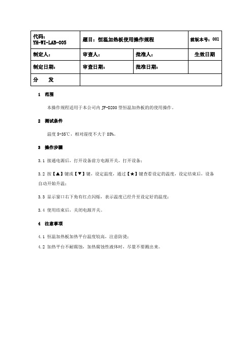
题目:恒温加热板使用操作规程 审查人: 审查日期: 批准人: 批准日期:
前版本号:001
生效日期
1 范围 本操作规程适用于本公司内 JF-D200 型恒温加热板的的使用操作。 2 测试条件 温度 5-35℃,相对湿度不大于 85%。 3 操作步骤 3.1 接通电源后,打开设备前方电源开关,打开设备; 3.2 按【▲】键或【▼】键,设定温度,通过【★】键查看设定的温度,设定结束后,设备 自动开始升温; 3.3 显示窗口右下角有红点闪烁,表示温度已经升至设定好的温度; 3.4 使用结束后,关闭电源开关。 4 注意事项 4.1 恒温加热板加热平台温度较高,注意防烫; 4.2 加热平台不耐腐蚀,加热腐蚀性液体时,尽量不要溅出来。
恒温电子恒温器手册说明书

Fan coil units3PictogrammesManual cool/heat changeoverAutomatic cool/heat changeover based on water temperatureAutomatic cool/heat changeover based on air temperatureControl of the 3-way/4-port ON/OFF valve. The water valve shut-off once the desired temperature is reached.The controller controls the electric heater as integration or replacement of the hot water heating system. When the operating mode selector witch is turned on “electric heater” and the electric heater is turned on, the fan runs continuously at medium speed.The fan speed can be set at one of the 3 speeds (low, medium or maximun) by turning the operation mode selector.The fan speed is switched automatically based on the difference between the temperature set on the thermostat and the room temperature.Optimised comfort cooling. When the fan coil has reached the desired setpoint, the fan will operate at medium speed and at regular intervals to ensure constant room temperature and lower sound.The controller prevents the fan coil unit from operating in one mode, if the required water temperature is not achieved to operate in the selected mode.The dead zone is a temperature interval close to the set temperature. When the air is warmer/cooler than the top/lower limit of the neutral zone, the cooling/ heating mode is selected.FWV FWL FWM01234567891011kWFWD24681012141618202224kWFWB24681012141618202224kWFan Coil Reference 2-pipe4-pipeProduct portfolioFan Coil Reference 2-pipe4-pipeCooling HeatingFan Coil Reference 2-pipe4-pipeDaikin fan coil units deliver quiet, reliable, controllable comfort of air conditioning without all the noise of other central systems.Fan coil units are a highly efficient means of turning a water chiller or hot water boiler into an efficient, quiet air conditioning system.The units are super quiet because the only moving part is the fan; making them ideal for use in offices, hotels and the home.The new range of fan coil units offers 5 models, of which 3 in flexible application. A wide range of accessories is available.For the ultimate in quiet, controllable air conditioning with all the comfort but none of the bulk or noise, the clear choice is Daikin.Easy to installFast and easy field set up, ready for use!KEY HOLE SYSTEM / LEVELLING•Quick fixing system for wall/ceiling mounting Advantage : No need to unscrew the nut •Units just need to be perfectly leveledAdvantage : No need to calculate the condensate drainageWATER CONNECTION •Pre-assembled 3-way/4-port ON/OFF valves are available •Valve packages are insulated, no extra drain pan required •Valve packages contain balancing valves and sensor pocket •Valve packages can be factory-mounted and are leak tested•Same valve package can be installed vertically and horizontally, on the right or on the left side of the unit without changeAdvantage : Easy to connect even when space is limitedCONDENSATE DRAINAGE•Condensate drain pan features slopes to reduce water accumulation •Supplied with flexible rubber hose pipe for easy connectionAdvantage : Eliminates the need to align drain pan outlet with customer pipingAdvantage : No need for collar if pipe diameter is compatibleQUICK ELECTRICAL CONNECTIONS•Fast-on connections for electrical options : no tools needed •Controls are already factory-wired and testedAdvantage : Control panel no longer needs to be opened (external customer connections)•Wiring diagram on the cover of the electrical boxEasy to maintainLow maintenance and high effeciency QUICK REMOVAL OF WASHABLE FILTER•No tools needed•Same system on vertical and horizontal unitsAdvantage: very fast filter removalELECTRIC HEATER RESETTING•No relay up to 2kW capacityAdvantage: even quieter operation•Manual reset easily accessible•Equipped with two overheat cut-out thermostats(manual & automatic reset)Advantage: anticipates the upcoming standardsFAN MOTOR/CONTROL PANEL ACCESSIBILITY• 4 screws to access to the fan motor•Fan board is removable without bringing the unit down•Motor is life-lubricated and has a life span of 40,000 hours•Control panel removable by a single screw•Can be unfolded for a better component access•Removable grilles•Easy access to control valvesSTRUCTURE•Modular concept•Height of the units only 240mm for all the sizes•Cooling coil and fan module is made of:-galvanised sheet steel-internally insulated (with 3mm close-cell polyurethane)•Key-hole system for fast mounting•Rubber anti-vibration damper to isolate the unit from supporting structure •Straight duct connector is mounted to both suction and discharge side (width 30mm)• A template is available in the carton box for easy connection to the ceiling HEAT EXCHANGER•3, 4 or 6 stage row cooling coil•Standard left handed water connections + air-purge(water connections can easily be turned)•Drain pan can to collect the condensate from:-Heat exchanger-Regulating valvesFAN MOTOR ASSEMBLY•1, 2 or 3 centrifugal fans with forward profile blades, dynamically andstatically balanced•7-speed electrical motors (with thermal protection on windings)•All 7 speeds pre-wired in the factory in the terminal block of the switch box •To reduce the requested installation space is the terminal block located onthe same side as the water connectionsAIR FILTER•Located in the air inlet•Removable from the bottom•Made of acrylic fiber, filter class EU2STRUCTURE•Possibility of installation both in horizontal and vertical position•Reduced height 280mm up to model 10•The unit is made of:- galvanised sheet steel- insulated with noise-proof/anti-condensing material(self-extinguishing in Class 1, with a thickness of 10mm)•Key-hole system for fast mounting•Straight duct connector is mounted to discharge side(width 30mm)HEAT EXCHANGER• 1 or 2 stage row cooling coil•Standard left handed water connections + air-purge•System for collecting and discharging condensate setup either for ceiling or wall mounting.FAN MOTOR ASSEMBLY•Dual intake centrifugal fans made of aluminum, dynamically and statically balanced •3-speed electric motor, installed on vibration damping supports(with thermal protection on windings)AIR FILTER•Air-intake module + Filter is standard delivered with each unit•Removable filter from the bottom•Made of acrylic fiber, filter class EU2EPIMSA6EPIA6FWV/L/M FWB FWD01y02y y03y y04y y y05y06y yx /v07y 08yx /v x /v09x /v 10yx /v x /v12v 16v 18vy v /x vEasy to control !The new fan coil units can be operated by 3 different controllers:• electronic control built-in (ECFWEB6)• electronic control remote (ECFWER6)• electromechanical control built-in (ECFWMB6)The electronic control consists of:•Operating mode selector , to turn the fan coil on and off,to choose the type of operating mode (automatic or at fixed speed) and to control the electric heating.•Cooling / Heating selector•Operational LEDs that indicates the current operation mode•Thermostat to control the room temperature•Free contacts for external enabling signal that may switch on or off the unit.• Free contacts for centralized cool/heat changeover • Water temperature probe • Air temperature probeSeveral configurations are possible by changing dip switches.The electromechanical controller includes a fan speed selector (3 speeds + stop) and manual cool/heat changeover. In case of the on/off valves, control can also be done through this controller.Power interface / master slave interfaceAn additional interface is required for units with a current greater than 1,12A.Master slave interface (EPIMSA6: 4x3A)For remote control of up to 4 fan coil units, an optional master/slave interface can be installed. Up to 3 EPIMSA6can be connected in parallel (--> max. 12 fan coils).Power interface (EPIA6: 1x16A)This is absolutely required for connection of ECFWER6 to FWD12 to18. It can be used as an alternative for EPIMSA6for all other fan coils.Master slave interface is only needed in case of remote control of multiple fan coil unitsObigation to use master slave interface or power interface Obligation to use power interfaceControl featuresBasic control functionsOptionsCooling/heating changeover2-p i p e4-p i p eCOOLINGTotal capacity (H)kW Sensible capacity (H)kW Water flow l/h Pressure drop kPa HEATINGHeating capacity (H)kW Water flow l/h Pressure drop kPa Power input HW Coil water volume lAir flowH/M/L m 3/h Sound power level H/M/L dBA WeightFWV kg FWM kg FWL kg COOLINGTotal capacity (H)kW Sensible capacity (H)kW Water flow l/h Pressure drop kPa Cooling coil water volume l HEATINGHeating capacity (H)kW Water flow l/h Pressure drop kPa Heating coil water volume l Power input H W Air flowH/M/L m 3/h Sound power level H/M/L dBA WeightFWV kg FWM kg FWL kgWater connections inch Max. absorbed current WDimensions FWV/FWL mm FWM mmPower supplyV/~/HzFWV/FWL/FWM01-10C**010203040608101.542.09 2.93 4.33 4.77 6.718.711.20 1.51 2.113.15 3.654.91 6.382653595047458201,1541,498131311121412192.14 2.79 3.815.636.367.8311.12653595047458201,1541,498910991091336466287891822440.50.71 1.4 1.4 2.1 2.1319/233/178344/271/211442/341/241706/497/361785/605/4701,011/771/5701,393/1,022/64247/39/3452/44/3650/44/3855/48/4059/52/4459/52/4466/58/481920253031414114151923233232202127323344441.5 1.79 2.87 4.26 4.67 6.648.551.17 1.46 2.07 3.09 3.57 4.85 6.262583084947338031,1421,471131311121412190.50.71 1.4 1.4 2.1 2.12.23 2.07 2.91 4.51 4.677.919.301961822863964656948167851010890.20.20.30.40.40.60.63659628789182244307/225/174327/261/205431/332/238690/490/356763/593/460998/765/5651,362/1,007/63647/39/3454/48/4250/45/3855/48/4059/53/4659/52/4466/58/482021263233444415162025253434212228343546461/2"1/2"1/2"1/2"1/2"3/4"3/4"0.160.210.270.390.380.80 1.12564x774x226564x984x226564x1,194x226564x1,404x251535x584x224535x794x224535x1,004x224535x1,214x249230/1/5001020304060810FWV FWL FWM ESRH02A6ESRH03A6ESRH06A6ESRH10A6x x x EEH01A6EEH02A6EEH03A6EEH06A6EEH10A6x x x E2MV03A6E2MV06A6E2MV10A6x x x E4MV03A6E4MV06A6E4MV10A6x x x YFSTA6xx x EAIDF02A6EAIDF03A6EAIDF06A6EAIDF10A6--x ESFV06A6ESFV10A6x -x ESFVG02A6ESFVG03A6ESFVG06A6ESFVG10A6x --EFA02A6EFA03A6EFA06A6EFA10A6x -x ERPV02A6ERPV03A6ERPV06A6ERPV10A6x x -ECFWMB6x x -ECFWEB6x x -ECFWER6x x x EPIMSA6x x x EDPVA6x x x EDPHA6-xx2-p i p e ( **= T N o r T V )4-p i p e ( **= F N )** = T N (2-p i p e , w i t h o u t v a l v e s ), T V (2-p i p e , w i t h v a l v e s ), F N (4-p i p e , w i t h o u t v a l v e s )Additional single row heat exchanger*Electric heater**2-pipe ON-OFF 3-way motor driven valve with complete mounting kit*4-pipe ON-OFF 3-way motor driven valve with complete mounting kit*(**)Fan stop thermostat**(only for ECFWMB6)Air intake & discharge grille +front filter fixing kit for concealed models Supporting feet(= supporting brackets + covers)Supporting feet + grille Manual fresh air intake louver Rear panel for vertically installed units Controller - electromechanical built-in**Controller - electronic built-in + water probe**Controller - electronic remote + water probe Power interface for connection of up to 4 FCU to a single control panel Vertical drain pan Horizontal drain panOption description * C a n b e o r d e r e d f a c t o r y m o u n t e d ** f a c t o r y m o u n t e d o n r e q u e s tMeasuring conditions (at nominal air flow and ESP) COOLING • Air temperature entering the unit: 27°C/19°C • Water temperature entering the unit 7°C • Water temperature rise 5 KHEATING • Room air temperature 20°C • For 2 pipe units : Water inlet temperature 50°C - Water flow rate same as for the cooling test • For 4 pipe units : - Water inlet temperature 70°C - Water temperature decrease 10 KFWB02-10AT 10Additional heat exchanger 3-way valve std h/e 3-way valve add. h/e 2-way valve std h/e 2-way valve add. h/e Electric heater Fan stop thermostat Power interface (*)Master slave interface (*)Controller electronic - remoteOption description 020304050607080910EAH04A6EAH07A6EAH10A6factory mounted on requestE2MV307A6E2MV310A6factory mounted on requestE2MV207A6E2MV210A6factory mounted on requestYFSTA6-EPIA6EPIMSA6ECFWER60203040506070809104008001,2007165592.61 3.14 3.49 5.08 5.45 6.477.578.6710.341.88 2.16 2.34 3.6 3.87 4.4 5.23 5.96 6.94485395988739361,1111,2991,4881,77481411158142121265.47 6.01 6.4710.3111.3912.2815.0516.8518.784805275679049991,0771,3191,4791,647710812710161518232426313335434548239x1,039x609239x1,389x609239x1,739x6093.14 5.9912.82755261,1233587917239x788x243239x1,138x243239x1,497x3351061922940.510.94 1.28586069230V/1~/50HzFWB2-p i p e /4-p i p e Air flow ratem 3/h Available static pressure Pa COOLINGTotal capacity (H)kW Sensible capacity (H)kW Water flow l/h Pressure drop kPa HEATINGHeating capacity (H)kW Water flow l/h Pressure dropkPa Machine weight kg Dimensions (HxWxD)mm HEATINGHeating capacity (H)kW Water flow l/h Pressure dropkPa Weight kg Dimensions mm Power input (H)W Running curent (H)A Sound power level (H)dBAPower supply2-p i p eA d d . H e a t e x c h a n g e rMeasuring conditionsCOOLING 2-pipe: air: 27°CDB/19°CWB - entering water 7°C - leaving water 12°C HEATING 2-pipe: air: 20°CDB - entering water 70°C - leaving water 60°CSound power level according to ISO3741 - sound pressure calculated at 1.5m distance - Q=2(*) In combination with ECFWER6, EPIMSA6 or EPIA6 must be installed for FWB08-1011Notes:1. The valves for FWD12-16-18 do not contain piping nor drain pan.2. Requires electronic control.3. Neglecting the absolute requirement to install an additional interface (EPIA6 or EPIMSA6) to FWD06 -->18 may cause fire or other damage to the equipment.4. In combination with ECFWER6, EPIMSA6 or EPIA6 must be installed for FWD06-10.5. In combination with ECFWER6, EPIA6 must be installed for FWD12-18.Electric heater: small (2)Electric heater: big (2)2-pipe 3-way valve (1)4-pipe 3-way valve (1)Vertical drain pan Horizontal drain pan Fan stop thermostatFresh air intake louvers (motorised) Controller - electronic remote + water probe (3)Master / Slave Interface (4)Power interface (5)Option description 2- p i p e / 4-p i p eCOOLINGTotal capacity kW Sensible capacity kW Water flow (H)l/h Pressure drop (H)kPa HEATINGHeating capacity kW Water flow (H)l/h Pressure drop (H)kPa Available static pressure Pa Weight kg COOLINGTotal capacity kW Sensible capacity kW Water flow (H)l/h Pressure drop (H)kPa HEATINGHeating capacity kW Water flow (H)l/h Pressure drop (H)kPa Available static pressure Pa Weight kg Air flow rate m 3/h Power input W Water connections inch Max. absorbed current A Dimensions mm Sound power level OveralldBA Power supplyV/~/HzFWD04-18A*2-p i p e ( *= T )4-p i p e ( *= F )Measuring conditions (at nominal air flow and ESP) COOLING • Air temperature entering the unit: 27°C/19°C • Water temperature entering the unit 7°C • Water temperature rise 5 KHEATING • Room air temperature 20°C • For 2 pipe units : Water inlet temperature 50°C - Water flow rate same as for the cooling test • For 4 pipe units : - Water inlet temperature 70°C - Water temperature decrease 10 K040608101216183.90 6.207.808.8211.9016.418.33.08 4.65 6.527.369.3612.814.16741,0641,3391,5142,0562,8333,140172424162634454.057.719.4310.7914.4519.8121.926741,0641,3391,5142,0562,8333,140142020132128376658686497145134334147496577803.90 6.207.808.8211.9016.418.33.08 4.65 6.527.169.3612.814.16741,0641,3391,5142,0562,8333,140172424162634454.49 6.629.219.2115.8621.1521.153495818088081,3921,8561,85691513131216166353635992138128354350527183868001,2501,6001,6002,2003,0003,0001772743153255309911,0013/43/43/43/41110.95 1.58 1.971.97 3.21 5.375.37280x754x559280x964x559280x1,174x559352x1,174x718352x1,384x71866697272747878230/1/5004060810121618EDEH04A6EDEHS06A6EDEHS10A6EDEHS12A6EDEHS18A6EDEH04A6EDEHB06A6EDEHB10A6EDEHB12A6EDEHB18A6ED2MV04A6ED2MV10A6ED2MV12A6ED2MV18A6ED4MV04A6ED4MV10A6 2 x ED2MV12A62 x ED2MV18A6EDDPV10A6EDDPV18A6EDDPH10A6EDDPH18A6YFSTA6EDMFA04A6EDMFA06A6EDMFA10A6EDMFA12A6EDMFA18A6ECFWER6EPIMSA6----EPIA6FWDE P C E 04-25B / C D / 04/06 L a M o v i d a P r i n t e d o n n o n -c h l o r i n a t e d p a p e r / P r i n t e d i n B e l g i u mDaikin products are distributed by:Zandvoordestraat 300B-8400 Oostende, Belgium The present publication is drawn up by way of information only and does not constitute an offer binding upon Daikin Europe N.V .. Daikin Europe N.V . has compiled the content of this publication to the best of its knowledge. No express or implied warranty is given for the completeness, accuracy, reliability or fitness for particular purpose of its content and the products and services presented therein. Specifications are subject to change without prior notice. Daikin Europe N.V . explicitly rejects any liability for any direct or indirect damage, in the broadest sense, arising from or related to the use and/or interpretation of this publication. All content is copyrighted by Daikin Europe N.V .Daikin Europe N.V . is approved by LRQA for its Quality Management System in accordance with the ISO9001standard. ISO9001 pertains to quality assurance regarding design, development, manufacturing as well as to services related to the product.ISO14001 assures an effective environmental management system in order to help protect human health and the environment from the potential impact of our activities, products and services and to assist in maintaining and improving the quality of the environment.Daikin units comply with the European regulations that guarantee the safety of the product.Daikin Europe NV participates in the Eurovent Certification Programme for Air Conditioners (AC),Liquid Chilling Packages (LCP) and Fan Coil Units (FC); the certified data of certified models are listed in the Eurovent Directory.Daikin’s unique position as a manufacturer of air conditioning equipment, compressors and refrigerants has led to its close involvement in environmental issues. For several years Daikin has had the intention to become a leader in the provision of environmental friendly products. This challenge demands the eco design and development of a wide range of products and an energy management system; which involves energy conservation and reduction of waste.。
恒温设备说明书

Page 1Copyright © 2020 Sensata Technologies, Inc. Set Temperature 45°C 113°FSwitching voltage max.250Vac Switching current max. 16A | FCTEPUMP DRY RUNNING SENSORSPECIFICATIONSThe FCTE is a heat sensor, which is attached to the outlet pipe from a pump. This device works by reacting to the temperature at the outlet of any centrifugal type pump, which will rapidly rise past 45° if the inlet water level falls below the centre line of the inlet. The unit will cut off the electrical supply to the pump, so protecting it from damage. Manual resetting of this unit allows the pump to restart.TechnicalFeatures• Prevents dry-running of pump • Prevents overheating of seals• High power switching capacity21Set Temperature 45°C 113°F Switching voltage max.250Vac SPECIFICATIONSwitching current max. resistive 16A Pipe diameter range20-200mmPage 2CONTACT USCynergy3 Components Ltd.7 Cobham Road,Ferndown Industrial Estate, Wimborne, Dorset,BH21 7PE, United KingdomCopyright © 2021 Sensata Technologies, Inc.Sensata Technologies, Inc. (“Sensata”) data sheets are solely intended to assist designers (“Buyers”) who are developing systems that incorporate Sensata products (also referred to herein as “components”). Buyer understands and agrees that Buyer remains responsible for using its independent analysis, evaluation and judgment in designing Buyer’s systems and products. Sensata data sheets have been created using standard laboratory conditions and engineering practices. Sensata has not conducted any testing other than that specifically described in the published documentation for a particular data sheet. Sensata may make corrections, enhancements, improvements and other changes to its data sheets or components without notice.Buyers are authorized to use Sensata data sheets with the Sensata component(s) identified in each particular data sheet. HOWEVER, NO OTHER LICENSE, EXPRESS OR IMPLIED, BY ESTOPPEL OR OTHERWISE TO ANY OTHER SENSATA INTELLECTUAL PROPERTY RIGHT, AND NO LICENSE TO ANY THIRD PARTY TECHNOLOGY OR INTELLECTUAL PROPERTY RIGHT, IS GRANTED HEREIN. SENSATA DATA SHEETS ARE PROVIDED “AS IS”. SENSATA MAKES NO WARRANTIES OR REPRESENTATIONS WITH REGARD TO THE DATA SHEETS OR USE OF THE DATA SHEETS, EXPRESS, IMPLIED OR STATUTORY, INCLUDING ACCURACY OR COMPLETENESS. SENSATA DISCLAIMS ANY WARRANTY OF TITLE AND ANY IMPLIED WARRANTIES OF MERCHANTABILITY, FITNESS FOR A PARTICULAR PURPOSE, QUIET ENJOYMENT, QUIET POSSESSION, AND NON-INFRINGEMENT OF ANY THIRD PARTY INTELLECTUAL PROPERTY RIGHTS WITH REGARD TO SENSATA DATA SHEETS OR USE THEREOF.All products are sold subject to Sensata’s terms and conditions of sale supplied at SENSATA ASSUMES NO LIABILITY FOR APPLICATIONS ASSISTANCE OR THE DESIGN OF BUYERS’ PRODUCTS. BUYER ACKNOWLEDGES AND AGREES THAT IT IS SOLELY RESPONSIBLE FOR COMPLIANCE WITH ALL LEGAL, REGULATORY AND SAFETY-RELATED REQUIREMENTS CONCERNING ITS PRODUCTS, AND ANY USE OF SENSATA COMPONENTS IN ITS APPLICATIONS, NOTWITHSTANDING ANY APPLICATIONS-RELATED INFORMATION OR SUPPORT THAT MAY BE PROVIDED BY SENSATA.Mailing Address: Sensata Technologies, Inc., 529 Pleasant Street, Attleboro, MA 02703, USA.ISO9001CERTIFIED cynergy3-fcte-v3 Rev: 04/22/21FCTEPump Dry Running SensorLimited. UK© 2020 Cynergy3 Components, All Rights Reserved. Specifications are subject to change without prior notice. Cynergy3 Components and the Cynergy3 Components logo are trademarks of Cynergy3 Components Limited.ISO 9001C ER TI FI ED。
加热器使用方法说明书

加热器使用方法说明书操作指南:加热器使用方法欢迎您购买并使用我们的加热器。
请您仔细阅读以下使用说明,以确保正确并安全地使用加热器。
第一步:准备工作1. 在使用加热器之前,请确保室内通风良好,以确保安全使用。
同时,需要确保电源电压符合加热器的工作要求。
2. 检查电源插座是否正常,不得使用破损或带有松动接触的插座。
第二步:安装加热器1. 将加热器放置在水平且稳定的表面上,远离易燃物和可燃物。
确保周围没有阻挡物,以免影响散热和正常工作。
2. 请勿堵塞或堆放物品在加热器周围,以保持其通风良好。
3. 将加热器的电源线插头插入电源插座,并确保插牢固。
第三步:使用加热器1. 打开加热器的电源开关,根据加热器面板上的操作按钮调整加热器的工作模式和温度。
您可以选择适合您需求的加热模式。
2. 在操作加热器时,请向下拉开门面板以便更好地操作加热器控制面板。
3.加热器配有安全温度控制装置,可以避免过热现象。
但为了安全起见,我们建议您不要将加热器使用时间过长,特别是在长时间离开室内的情况下。
4. 加热器温度可以通过控制面板上的温度按钮进行调节,根据您的需要提高或降低温度。
5. 当不使用加热器时,请及时关闭电源开关,并拔掉电源线插头,以确保安全。
第四步:加热器维护1. 加热器使用一段时间后,会有灰尘和杂物附着在加热器表面和过滤器上。
请定期使用干净的布或吸尘器清洁加热器表面和过滤器,以确保正常工作。
2. 请勿使用带有腐蚀性或破损的清洁剂清洁加热器,以免损坏加热器表面和内部零件。
3. 如发现加热器有故障或异常,请立即停止使用,拔掉电源插头,并联系专业人员进行检修。
第五步:安全注意事项1. 在加热器工作期间,请确保加热器周围没有易燃物或可燃物,如纸张、布料等。
同时,请不要在加热器上晾晒湿衣物。
2. 请勿将加热器放置在潮湿的环境中,以免影响加热器性能和安全。
3. 当加热器在工作时,请不要离开室内太远,以免发生意外。
尽量避免儿童或宠物接近加热器。
恒温箱设备操作规程(3篇)
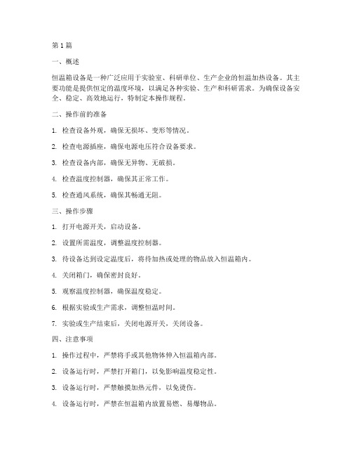
第1篇一、概述恒温箱设备是一种广泛应用于实验室、科研单位、生产企业的恒温加热设备。
其主要功能是提供恒定的温度环境,以满足各种实验、生产和科研需求。
为确保设备安全、稳定、高效地运行,特制定本操作规程。
二、操作前的准备1. 检查设备外观,确保无损坏、变形等情况。
2. 检查电源插座,确保电源电压符合设备要求。
3. 检查设备内部,确保无异物、无破损。
4. 检查温度控制器,确保其正常工作。
5. 检查通风系统,确保其畅通无阻。
三、操作步骤1. 打开电源开关,启动设备。
2. 设置所需温度,调整温度控制器。
3. 待设备达到设定温度后,将待加热或处理的物品放入恒温箱内。
4. 关闭箱门,确保密封良好。
5. 观察温度控制器,确保温度稳定。
6. 根据实验或生产需求,调整恒温时间。
7. 实验或生产结束后,关闭电源开关,关闭设备。
四、注意事项1. 操作过程中,严禁将手或其他物体伸入恒温箱内部。
2. 设备运行时,严禁打开箱门,以免影响温度稳定性。
3. 设备运行时,严禁触摸加热元件,以免烫伤。
4. 设备运行时,严禁在恒温箱内放置易燃、易爆物品。
5. 设备运行时,严禁将重物放置在恒温箱内,以免损坏设备。
6. 设备长时间未使用,需定期检查设备性能,确保其正常工作。
7. 设备运行过程中,如发现异常现象,立即停止使用,检查原因并排除故障。
五、维护保养1. 定期清洁设备,保持设备内外部清洁。
2. 定期检查设备各部件,确保其正常工作。
3. 定期检查电源线路,确保其安全可靠。
4. 设备运行一段时间后,检查加热元件,确保其无损坏。
5. 定期检查温度控制器,确保其准确度。
六、安全措施1. 操作人员需经过专业培训,熟悉设备操作规程。
2. 操作人员需穿戴好防护用品,如防护手套、防护眼镜等。
3. 设备运行过程中,操作人员不得离开现场,确保设备安全运行。
4. 设备运行过程中,严禁无关人员进入操作区域。
5. 设备发生故障时,立即停止使用,及时报修。
本规程适用于所有恒温箱设备,操作人员应严格遵守,以确保设备安全、稳定、高效地运行。
恒温恒湿高温高压高压热风试验箱操作说明书

恒温恒湿高温高压高压热风试验箱操作说明书一、概述恒温恒湿高温高压热风试验箱是一种用于模拟高温高压环境的设备,广泛应用于电子、汽车、航空航天等领域的产品试验。
本操作说明书将为用户提供正确、安全地操作高温高压热风试验箱的方法和步骤。
二、安全须知1. 使用前请先阅读本操作说明书,确保了解设备的基本原理和操作规程。
2. 操作前请检查试验箱的电源线是否连接稳固,避免电源松动而导致触电事故。
3. 在操作试验箱时,应戴上防护手套、护目镜等安全防护装备,以免发生意外伤害。
4. 请勿在试验箱内存放易燃、易爆物品,以免引发火灾或爆炸。
5. 若试验箱发生故障或异常情况,请立即停止使用,并通知维修人员进行检修。
三、操作步骤1. 打开试验箱a. 确保试验箱的电源已经连接,并检查电源线是否安全可靠。
b. 按下试验箱上的电源开关,待指示灯亮起表示试验箱已经打开。
2. 设置温度和湿度a. 在试验箱控制面板上输入需要的温度和湿度数值。
b. 确认输入数值后,按下温度和湿度设定按钮。
3. 加载待测样品a. 打开试验箱的门,将待测样品放置在试验箱内部的样品托盘上。
b. 关闭试验箱的门,确保门已经牢固关闭。
4. 启动试验a. 按下试验箱控制面板上的启动按钮,试验箱将开始进行恒温恒湿环境的模拟。
b. 观察试验箱内温度和湿度的显示,确保其稳定在设定的数值范围内。
5. 结束试验a. 在试验时间到达或试验完成时,按下停止按钮,停止试验箱的运行。
b. 等待试验箱内温度和湿度恢复到常温常湿状态后,再打开试验箱的门,取出待测样品。
四、维护与故障排除1. 定期清洁试验箱内部的灰尘和污垢,以免影响试验箱的正常运行。
2. 检查试验箱的温湿度传感器是否正常,如有异常及时更换。
3. 若试验箱出现故障或无法正常运行,请联系售后服务中心进行维修。
五、注意事项1. 在试验箱运行过程中,应定期检查电源和线路是否正常,以免因电气故障引发安全事故。
2. 请勿私自拆卸或更换设备的零部件,避免损坏设备或引发安全隐患。
海鲜恒温机操作方法
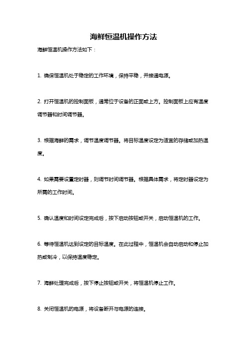
海鲜恒温机操作方法
海鲜恒温机操作方法如下:
1. 确保恒温机处于稳定的工作环境,保持平稳,并接通电源。
2. 打开恒温机的控制面板,通常位于设备的正面或上方。
控制面板上应有温度调节器和时间调节器。
3. 根据海鲜的需求,调节温度调节器。
将目标温度设定为适宜的存储或加热温度。
4. 如果需要设置定时器,则调节时间调节器。
根据具体需求,将定时器设定为所需的工作时间。
5. 确认温度和时间设定完成后,按下启动按钮或开关,启动恒温机的工作。
6. 等待恒温机达到设定的目标温度。
在此过程中,恒温机会自动启动和停止加热或制冷,以保持温度稳定。
7. 海鲜处理完成后,按下停止按钮或开关,将恒温机停止工作。
8. 关闭恒温机的电源,将设备断开与电源的连接。
请注意:操作方法可能根据不同品牌和型号的恒温机略有不同。
在操作之前,请务必仔细阅读和理解恒温机的使用说明书,并按照说明书上的具体操作步骤进行操作。
如有任何疑问或不清楚的地方,请联系设备制造商或专业人士寻求帮助。
恒温控制器用户操作指南说明书
Step 11. Enter to the Thermocouple Type Input Submenu Press d to display flashing, previously selected Thermocouple type.Step 12. Scroll through available selection of TC types Press b to sequence thru flashing Thermocouple types,(select k -for type "K" CHROMEGA ®/ALOMEGA ®)J K T E N DIN J R S B C - TC types J k t E N dN J R S b C - DisplayStep 13. Store TC typeAfter you have selected the Thermocouple type press d to store your selection, the instrument automatically advances to the next menu item.Step 14. Enter to Reading Configuration MenuThe display shows RDG Reading Configuration, which is the top menu for 4 submenus: Decimal Point, Degree Units,Filter Constant and Input/Reading Submenus.Step 15. Enter to Decimal Point Submenu Press d to show DEC Decimal Point.Step 16. Display the Decimal Point positionPress d again to display the flashing Decimal Point position.Step 17. Select the Decimal Point position Press b to select FFF.F Decimal Point position.Step 18. Store selected Decimal Point positionBy pressing d momentarily the Decimal Point position will be stored and the instrument will go to the next menu item.Step 19. Enter to Temperature Unit Submenu Display shows TEMP Temperature Unit.Step 20. Display available Temperature Units Press d to display the flashing Degree °F or °C .Step 21. Scroll through Temperature Units selection Press b to select °F Degree.Step 22. Store the Temperature UnitPress d to display momentarily that the Degree Unit has been stored and the instrument will go automatically to the next menu item.Step 23. Enter the Filter Constant Submenu Display shows FLTR Filter Constant Submenu.Step 24. Display the Filter Constant Value Submenu Press d to display the flashing, previously selected Filter Constant.Step 25. Scroll through available Filter Constants Press b to sequence thru Filter Constants 0001, 0002,0004, 0008, 0016, 0032, 0064and 0128.Step 26. Store the Filter ConstantPress d momentarily to store 0004Filter Constant and the instrument will automatically go to the next menu item.Step 27. Enter Alarm 1 MenuPress a until the ALR1Alarm 1 Menu appears on the Display. In the following steps we are going to DisableLatch, Active Above, Deadband 020.0, and above Setpoint 1Value will activate Alarm 1.Step 28. Select Latch Type SubmenuPress d to display flashing DSBL / ENBL .If flashing DSBL is displayed, press a , if ENBL is displayed, press buntil DSBL is displayed, then press d to store and go to the next menu item.Step 29. Select the Above Type of Active Submenu Press d . If flashing ABoV Above is displayed, press a ,otherwise press b until ABoV is displayed. Press d to store and advance to next menu item.MQS3716-SM/0305iLD24 Big Display Universal Temperature&ProcessSimplified Menu (-SM)WARRANTY/DISCLAIMEROMEGA ENGINEERING, INC. warrants this unit to be free of defects in materials and workmanship for a period of 61 months from date of purchase. OMEGA’s WARRANTY adds an additional one (1) month grace period to the normal five (5) year product warranty to cover handling and shipping time. T his ensures that OMEGA’s customers receive maximum coverage on each product.If the unit malfunctions, it must be returned to the factory for evalua-tion. OMEGA’s Customer Service Department will issue an Authorized Return (AR) number immediately upon phone or written request. Upon examination by OMEGA, if the unit is found to be defective, it will be repaired or replaced at no charge. OMEGA’s WARRANTY does not apply to defects resulting from any action of the purchaser, includ-ing but not limited to mishandling, improper interfacing, operation outside of design limits, improper repair, or unauthorized modifica-tion. This WARRANTY is VOID if the unit shows evidence of having been tampered with or shows evidence of having been damaged as a result of excessive corrosion; or current, heat, moisture or vibration; improper specification; misapplication; misuse or other operating conditions outside of OMEGA’s control. Components in which wear is not warranted, include but are not limited to contact points, fuses, and triacs.OMEGA is pleased to offer suggestions on the use of its vari-ous products. However, OMEGA neither assumes responsibil-ity for any omissions or errors nor assumes liability for any damages that result from the use if its products in accordance with information provided by OMEGA, either verbal or writ-ten. OMEGA warrants only that the parts manufactured by the company will be as specified and free of defects. OMEGA MAKES NO OTHER WARRANTIES OR REPRESENTATIONS OF ANY KIND WHATSOEVER, EXPRESSED OR IMPLIED, EXCEPT THAT OF TITLE, AND ALL IMPLIED WARRANTIES INCLUDING ANY W ARRANTY OF MERCHANTABILITY AND FITNESS FOR A PARTICULAR PURPOSE ARE HEREBY DISCLAIMED. LIMITATION OF LIABILITY: The remedies of purchaser set forth herein are exclusive, and the total liability of OMEGA with respect to this order, whether based on contract, warran-ty, negligence, indemnification, strict liability or otherwise, shall not exceed the purchase price of the component upon which liability is based. In no event shall OMEGA be liable for consequential, incidental or special damages.CONDITIONS: Equipment sold by OMEGA is not intended to be used, nor shall it be used: (1) as a “Basic Component” under 10 CFR 21 (NRC), used in or with any nuclear installation or activity; or (2) in medical appli-cations or used on humans. Should any Product(s) be used in or with any nuclear installation or activity, medical application, used on humans, or misused in any way, OMEGA assumes no responsibility as set forth in our basic WARRANT Y/DISCLAIMER language, and, additionally, purchaser will indemnify OMEGA and hold OMEGA harmless from any liability or damage whatsoever arising out of the use of the Product(s) in such a manner.RETURN REQUESTS/INQUIRIESDirect all warranty and repair requests/inquiries to the OMEGA Customer Service Department. BEFORE RE URNING ANY PRODUC (S) O OMEGA, PURCHASER MUS OB AIN AN AUTHORIZED RETURN (AR) NUMBER FROM OMEGA’S CUSTOMER SERVICE DEPART MENT (IN ORDER T O AVOID PROCESSING DELAYS). T he assigned AR number should then be marked on the outside of the return package and on any correspondence.FOR WARRANTY RETURNS, please have the followinginformation available BEFORE contacting OMEGA:1. Purchase Order number under which the product was PURCHASED,2.3. Model and serial number of the product under warranty, and Repair instructions and/or specific problems relative to the product.FOR NON-WARRANTY REPAIRS, consult OMEGA for current repair charges. Have the following information available BEFORE contacting OMEGA:1. P urchase Order number to cover the COST of the repair or calibration,2.3.Model and serial number of the product, and R epair instructions and/or specific problems relative to the product.OMEGA’s policy is to make running changes, not model changes, whenever an improvement is possible. This affords our customers the latest in technology and engineering.OMEGA is a trademark of OMEGA ENGINEERING, INC.© Copyright 2018 OMEGA ENGINEERING, INC. All rights reserved. T his document may not be copied, photocopied, reproduced, translated, or reduced to any electronic medium or machine-readable form, in whole or in part, without the prior written consent of OMEGA ENGINEERING, INC.***********************Servicing North America:Omega Engineering, Inc.Toll-Free: 1-800-826-6342 (USA & Canada only)Customer Service: 1-800-622-2378 (USA & Canada only) Engineering Service: 1-800-872-9436 (USA & Canada only) Tel: (203) 359-1660 Fax: (203) 359-7700 e-mail:**************For Other Locations Visit /worldwidehis Quick Start Reference provides information on setting up your instrument for basic operation. The latest complete Communication and Operational Manual as well as free Software and ActiveX Controls are available at or on the CD-ROM enclosed with your shipment .SAFETY CONSIDERATIONThe instrument is a panel mount device protected in accordance with EN 61010-1:2001, electrical safetyrequirements for electrical equipment for measurement, control and laboratory.Remember that the unit has no power-on switch. Building installation should include a switch or circuit-breaker that must be compliant to IEC 947-1 and 947-3.SAFETY:•Do not exceed voltage rating on the label located on the back of the instrument housing.•Always disconnect power before changing signal and power connections.•Do not use this instrument on a work bench without its case for safety reasons.•Do not operate this instrument in flammable or explosive atmospheres.EMC:•Whenever EMC is an issue, always use shielded cables. •Never run signal and power wires in the same conduit.•Use signal wire connections with twisted-pair cables.•Install Ferrite Bead(s) on signal wire close to the instrument if EMC problems persist.。
高温恒温器使用说明书

高温恒温器使用说明书正文本使用说明书详细介绍了高温恒温器的使用方法和注意事项,以确保用户正确、安全地操作该设备。
在阅读本说明书前,请确保已经仔细阅读并理解所有的内容。
一、产品概述高温恒温器是一种温度控制设备,能够在设定的温度范围内保持恒定温度。
该设备常被用于实验室、工业制造、医疗等领域,用于对样品、试剂、设备等进行温度控制。
二、使用方法1. 设备预热插入设备电源,并按下电源开关。
待设备面板显示出温度设置界面后,输入所需的温度参数,并按下启动按钮。
设备将开始加热,并自动达到设定温度。
2. 设置温度使用温度调节按钮可以对设备进行温度设定。
根据需要,可使用上下调节按钮进行微调。
在设定温度后,按下启动按钮开始加热。
3. 温度保持一旦设备达到设定温度,将会自动保持该温度。
设备将根据实时温度进行微调,以保证温度的恒定性。
4. 停止操作在使用结束后,按下停止按钮,设备将停止加热,并等待冷却后自动关闭。
三、安全事项1. 电源连接在使用设备之前,请确保电源线正确连接,且电源稳定可靠。
禁止使用破损的电源线。
2. 温度设定在设定温度时,请谨慎选择温度范围,并确保所设置的温度符合实际需求。
过高或过低的温度设定可能导致设备性能不稳定或发生故障。
3. 设备操作请在设备使用时遵循正常操作流程,禁止非专业人士随意操作设备。
特殊的操作需求请参阅设备的专门说明。
4. 设备维护定期对设备进行清洁和维护,以确保其正常运行。
对设备进行维修或更换零部件时,请寻求专业人员的帮助。
5. 使用环境设备需要在干燥、通风良好的环境下使用,禁止在潮湿或易燃物体附近使用设备。
6. 过热保护在设备运行期间,请确保四周空间充足,避免遮挡设备散热口。
设备内部温度过高时,会自动触发过热保护功能,并断开电源。
7. 紧急情况在设备出现故障或异常情况时,请及时切断电源,并联系售后服务中心或专业人士进行维修。
四、维修与保养1. 清洁在设备使用前后,请使用柔软的干布清洁设备的外壳及控制面板。
恒温加热台操作和维护保养规程

文件制修订记录
1.目的
建立恒温加热台的操作规程,使检验员正确使用恒温加热台,确保实验安全性。
2.适用范围
适用于检验人员使用恒温加热台。
3.操作规程
3.1水平放置好主机,接通电源。
3.2打开电源开关,按设置键“SET”,此时SV窗口显示单元处于闪烁,进入设置状态。
3.3通过三个箭头按键设置想要设定的温度,按移位键可在个位数十位数百位数之间切换。
3.4设定结束后再按“SET”键,此时窗口恢复原来显示,参数被储存,仪表进入工作状态。
3.5结束加热后,关闭电源开关,清理台面。
4.维护保养及注意事项
4.1机器工作过程中机壳温度较高,切不可用手触摸。
4.2加热板上切不可滴上任何液体,否则会导致高温情况下液体飞溅伤人。
4.3本机不宜在潮湿、可燃性、腐蚀性、高粉尘等恶劣环境下使用。
4.4定期用干布擦拭台面,保持干燥清洁。
贝多机电恒温加热平台使用说明书
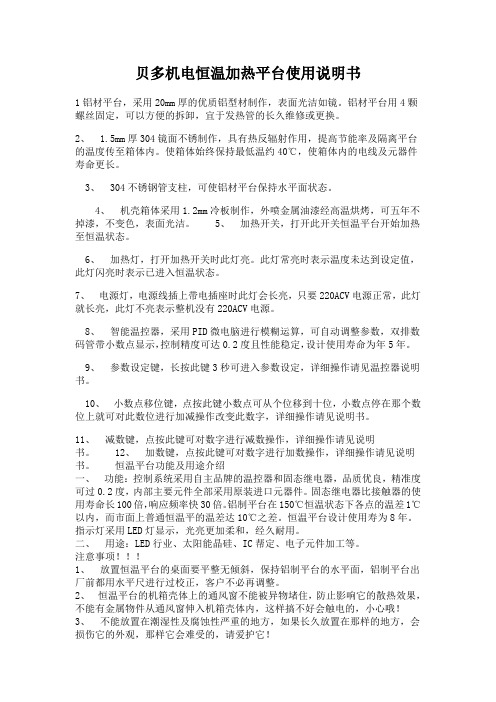
贝多机电恒温加热平台使用说明书1铝材平台,采用20mm厚的优质铝型材制作,表面光洁如镜。
铝材平台用4颗螺丝固定,可以方便的拆卸,宜于发热管的长久维修或更换。
2、 1.5mm厚304镜面不锈制作,具有热反辐射作用,提高节能率及隔离平台的温度传至箱体内。
使箱体始终保持最低温约40℃,使箱体内的电线及元器件寿命更长。
3、 304不锈钢管支柱,可使铝材平台保持水平面状态。
4、机壳箱体采用1.2mm冷板制作,外喷金属油漆经高温烘烤,可五年不掉漆,不变色,表面光洁。
5、加热开关,打开此开关恒温平台开始加热至恒温状态。
6、加热灯,打开加热开关时此灯亮。
此灯常亮时表示温度未达到设定值,此灯闪亮时表示已进入恒温状态。
7、电源灯,电源线插上带电插座时此灯会长亮,只要220ACV电源正常,此灯就长亮,此灯不亮表示整机没有220ACV电源。
8、智能温控器,采用PID微电脑进行模糊运算,可自动调整参数,双排数码管带小数点显示,控制精度可达0.2度且性能稳定,设计使用寿命为年5年。
9、参数设定键,长按此键3秒可进入参数设定,详细操作请见温控器说明书。
10、小数点移位键,点按此键小数点可从个位移到十位,小数点停在那个数位上就可对此数位进行加减操作改变此数字,详细操作请见说明书。
11、减数键,点按此键可对数字进行减数操作,详细操作请见说明书。
12、加数键,点按此键可对数字进行加数操作,详细操作请见说明书。
恒温平台功能及用途介绍一、功能:控制系统采用自主品牌的温控器和固态继电器,品质优良,精准度可过0.2度,内部主要元件全部采用原装进口元器件。
固态继电器比接触器的使用寿命长100倍,响应频率快30倍。
铝制平台在150℃恒温状态下各点的温差1℃以内,而市面上普通恒温平的温差达10℃之差。
恒温平台设计使用寿为8年。
指示灯采用LED灯显示,光亮更加柔和,经久耐用。
二、用途:LED行业、太阳能晶硅、IC帮定、电子元件加工等。
注意事项!!!1、放置恒温平台的桌面要平整无倾斜,保持铝制平台的水平面,铝制平台出厂前都用水平尺进行过校正,客户不必再调整。
恒温加热板使用说明

恒温加热板使用说明
恒温加热板是一种可以稳定控制加热温度的仪器。
在使用前,需要先了解一些基本的使用说明:
1.接通电源:将恒温加热板的电源插头接入220V电源插座,并开启电源开关。
2.设置加热温度:根据实际需要,调节恒温加热板的温度控制器,设定所需加热温度。
3.等待预热:恒温加热板具有延时预热功能,需要等待一段时间,待加热板达到预定温度后再进行操作。
4.将被加热物品放置于加热板上:将需要加热的物品放置在加热板上,并确保物品与加热板接触紧密。
5.加热过程中的注意事项:在加热过程中,需要注意加热温度的变化并随时监测被加热物品的变化。
同时,在使用高温加热板时需要注意安全事项,如避免接触热面、避免操作过程中发生意外等。
6.关机:在加热完成后,将温度控制器设置为“关”(或将电源开关关闭),并等待加热板冷却至自然温度后再进行下一步操作。
总之,使用恒温加热板需要注意安全、设置恰当的温度和时间等因素。
在使用过程中,如有不懂之处,可以参考说明书或联系相关人员进行指导。
恒温加热器使用说明书

恒温加热器使用说明书一、产品介绍恒温加热器是一种用于控制温度的设备,适用于实验室、工业生产等领域。
本产品采用先进的温度传感器和控制技术,能够实现精确的温度控制,具有稳定性好、操作简单等特点。
二、安全注意事项1. 本产品需在干燥、通风良好的环境下使用。
2. 请确保电源连接正确,接地可靠,以确保使用安全。
3. 仔细阅读产品说明书,并按照说明进行正确操作,避免不必要的事故发生。
4. 使用过程中应避免遮挡散热孔,避免过载使用。
5. 使用结束后,请拔掉电源插头,确保设备断电。
三、产品特点1. 温控范围广:本产品的温控范围可根据需要进行调整,满足不同的实验需求。
2. 温度稳定性好:经过精确的温度控制算法设计,保证设备稳定运行,提供精确的温度控制。
3. 操作简单:本产品采用触摸屏设计,界面简洁清晰,操作便捷,即使对设备不熟悉的用户也能够轻松上手使用。
4. 故障自诊断:设备具有故障自诊断功能,一旦出现故障,会自动报警并显示故障原因,方便用户快速排除故障。
四、使用方法1. 打开设备:接通电源后,按下电源按钮,待设备开机完成后进入待机状态。
2. 设置温度:通过触摸屏上的温度调节按钮,可自定义所需温度。
设定后,系统会根据设定值进行温度控制。
3. 启动加热:设定好温度后,点击启动加热按钮,设备将开始加热,并根据设定温度进行温度调节。
4. 监控温度:设备运行时,观察触摸屏上显示的实时温度值,确保温度始终在设定范围内。
5. 结束使用:使用完毕后,点击停止加热按钮,设备会停止加热并保持待机状态。
拔掉电源插头,确保设备断电。
五、故障排除1. 故障自诊断:设备出现故障时,会自动报警并显示故障原因,用户可根据报警信息进行故障排除。
2. 联系售后服务:若设备故障无法解决,请联系售后服务中心进行维修或更换。
六、维护保养1. 定期清洁:使用过程中请保持设备干燥,避免积尘。
定期用软布擦拭设备外壳,以保持清洁。
2. 防止碰撞:使用过程中请避免撞击设备,以免损坏设备外壳或内部元件。
加热台使用说明

加热台使用说明一、产品简介加热台是一种用于加热实验室器皿或样品的设备,主要用于科研、教学和工业生产中的加热实验。
其具有加热均匀、温度控制精确、安全可靠等特点,广泛应用于化学、生物、医药、食品等领域。
二、产品特点1. 加热均匀:加热台采用高效的加热元件,能够均匀地将热量传导到加热区域,确保样品或器皿受热均匀,有效提高实验的可靠性和准确性。
2. 温度控制精确:加热台配备了精密的温度控制系统,能够精确地控制加热区域的温度,满足不同实验的需求。
3. 安全可靠:加热台具有多重安全保护措施,如过温保护、漏电保护、过载保护等,确保用户在使用过程中的安全。
4. 操作简便:加热台的操作界面简单明了,用户只需按照说明书进行简单设置即可完成加热过程。
5. 多功能:加热台可配备不同规格的加热盘或加热模块,满足不同实验需求。
三、使用方法1. 准备工作:将加热台放置在稳定的工作台面上,并确保通电插头连接正常。
2. 设置温度:根据实验需求,使用加热台上的温度控制系统设置所需的加热温度。
可以通过旋转或按键方式进行设置。
3. 放置样品:将需要加热的器皿或样品放置在加热台的加热区域上,并确保其与加热板接触良好。
4. 开始加热:按下加热台上的启动按钮或开关,加热台开始加热。
此时,加热台会根据设置的温度自动控制加热功率,使加热区域温度逐渐升高。
5. 实验结束:实验完成后,按下加热台上的停止按钮或开关,加热台停止加热。
待加热区域温度降至安全范围后,可以取出样品或器皿。
四、注意事项1. 在使用加热台前,请先阅读并理解产品的使用说明书,确保正确操作。
2. 使用加热台时,请确保周围环境通风良好,避免因加热导致的气体或蒸汽聚集引发安全事故。
3. 加热台在加热过程中会产生高温,使用时请注意避免烫伤,避免将易燃物品放置在加热区域附近。
4. 加热台使用过程中,请勿随意拆卸或改变产品结构,以免影响产品的正常工作和安全性能。
5. 使用加热台时,请注意电源的安全使用,确保电源接地可靠,避免漏电或触电事故。
恒温加热台操作方法

恒温加热台操作方法恒温加热台是一种用于实验室和工业生产中的加热设备,可以提供稳定的温度环境。
下面是恒温加热台的详细操作方法。
1. 准备工作首先,检查恒温加热台的外观和内部结构是否完好。
确保加热板平整,无损坏或松动的部件。
接下来,检查加热台的电源线是否正常连接,并确保电源线安全可靠,没有破损或暴露的情况。
最后,确保加热台上没有杂物和易燃物品,以防止安全事故的发生。
2. 连接电源将恒温加热台的电源插头插入电源插座,并将另一端连接到加热台上。
然后打开电源开关,启动加热台。
在此过程中,要注意电源电压是否与加热台上标示的电源要求相符,以免损坏设备。
3. 设定温度恒温加热台一般配备数字控制面板,可以通过面板上的按钮或旋钮来设定温度。
根据实际需要,选择合适的温度范围,并使用面板上的调节装置将设定温度调整到所需的数值。
一般来说,恒温加热台的温度范围为室温至300。
4. 温度稳定设定温度后,恒温加热台会开始加热,并通过内置的控制系统来维持设定温度。
在这个过程中,加热台会根据温度传感器的反馈信号来控制加热功率的大小,以确保加热台表面的温度能够达到并稳定在设定温度。
一般来说,恒温加热台的温度稳定性要求在±1以内。
5. 放置样品当温度稳定后,可以将需要加热的样品放置在恒温加热台上。
根据需要,可以使用磁力搅拌器、恒温槽或其他设备来进行进一步的实验操作。
在放置样品时,要注意保持加热台表面的平整度和清洁度,以确保样品的均匀加热和实验的准确性。
6. 加热时间加热时间取决于所加热样品的性质和所需的温度变化速度。
在进行加热过程中,要根据实际情况调整加热功率和加热时间,以确保样品能够达到所需的温度。
在加热过程中,可以通过观察样品的颜色、气味和其他物理变化来判断加热的效果。
7. 关闭恒温加热台当实验完成或不再需要加热时,应及时关闭恒温加热台。
首先,调整控制面板上的温度设置为室温,并等待加热台表面的温度降至安全温度后,可以关闭电源开关,断开电源连接。
海鲜恒温机操作规程(3篇)

第1篇一、设备准备1. 确保海鲜恒温机处于良好状态,电源线、连接线、传感器等完好无损。
2. 检查恒温机内外清洁,无杂物。
3. 确认恒温机所在环境符合要求,通风良好,无腐蚀性气体。
二、开机操作1. 将恒温机电源插头插入电源插座,打开电源开关。
2. 确认恒温机显示屏正常,操作面板按键功能完好。
3. 根据所需温度,设置恒温机温度控制值。
设置范围一般为0℃-10℃。
4. 按下“启动”按钮,恒温机开始工作。
三、运行监控1. 恒温机运行过程中,密切关注显示屏显示的温度值。
2. 若发现温度异常波动,立即检查原因,调整温度控制值。
3. 定期检查海鲜恒温机运行状态,确保设备正常工作。
四、操作注意事项1. 操作人员需具备一定的设备操作技能和常识。
2. 在操作过程中,严禁触摸高温部件,以防烫伤。
3. 严禁在恒温机运行过程中打开箱门,以免影响制冷效果。
4. 操作人员应保持恒温机周围清洁,避免杂物进入。
5. 定期清理恒温机内部,保持设备良好状态。
6. 如遇设备故障,请立即停止使用,联系专业人员进行维修。
五、关机操作1. 当海鲜恒温机达到设定温度后,按下“停止”按钮。
2. 确认恒温机停止运行,关闭电源开关。
3. 检查恒温机内外清洁,无杂物。
六、维护保养1. 定期检查恒温机各部件,确保设备正常运行。
2. 检查电源线、连接线、传感器等是否完好,如有损坏,及时更换。
3. 清理恒温机内部,保持设备良好状态。
4. 定期检查设备接地情况,确保设备安全运行。
5. 根据设备使用年限,定期进行检修和维护。
通过以上海鲜恒温机操作规程,可以确保设备安全、稳定、高效地运行,为海鲜产品提供适宜的储存环境。
同时,操作人员应严格遵守操作规程,确保自身和他人的安全。
第2篇一、适用范围本规程适用于本公司生产、销售的海鲜恒温机的操作和维护。
二、操作步骤1. 开机前准备(1)检查电源插座是否正常,确保电源电压符合设备要求。
(2)检查设备外观是否完好,如有损坏请及时更换。
加热台操作说明
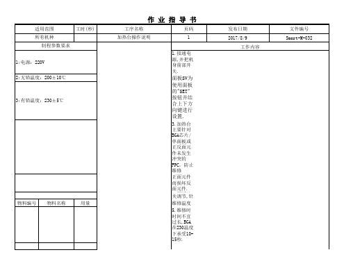
用量 1台 一瓶 1瓶 1只 1瓶 一台
注意事项 1:同一芯片加热不能超过三次,否则予以更换。 2:加热芯片时,手不要触碰加热台以避免烫伤。 制程特性 1.重要点:客户要求的管制 点 拟定: 符号 * 审核: 核准: 3:操作过程中切勿敲打或撞击加热装置,以免将工具损坏。 4:GT产品禁止用加热台维修,一律用热风枪维修。
3.加热台主要针对BGA芯片/单面板或正反面元件未发生冲突的FPC,防止维修 正面元件而损坏反面元件. 4.温度开关调节,针对芯片的的大小、厚度、不同焊锡材料、不同材质选用不同
物料编号
物料名称
用量
维修温度 5.维修时时间不宜过长,BGA在230温度下承受10-15秒. 6.维修时把BGA置于加热装置的上面,视锡融化后把芯片用捻 子拖到右边冷却板上 7.加热台应定期进行校验,检验其温度的准确性. 8.加热台使用时如有异常或其它功能不良时,请立即知会加热台维护人 员进行检修,切忌私自拆开.
作 业 指 导 书
适用范围 所有机种 制程参数要求 1:电源:220V 2:无铅温度:200±10℃ 3:有铅温度:230±5℃ 工时(秒) 工序名称 加热台操作说明 页码 1 发布日期 2017/8/9 工作内容 1.接通电源,并把机身前部开关. 文件编号 Smart-M-032
2.加热台面板SV为设置温度按钮,PV显示为实际温度,温度参数 使用面板的"SET"按钮并结合上下方向键进行设置.
温控器使用说明书
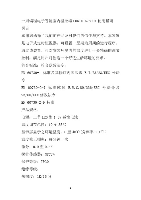
一周编程电子智能室内温控器LOGIC 578001使用指南引言感谢您选择了我们的产品及对我们的信任与支持。
本装置是电子式定时恒温器,可设置一星期为周期的运行程序。
通过该装置,可对安装环境内的温度进行十分精确的调节控制,满足用户对创造一个舒适生活环境的要求。
符合标准:符合欧盟法令:EN 60730-1 标准及其修订内容欧盟 B.T.73/23/EEC号法令EN 60730-2-7 标准欧盟 E.M.C.89/336/EEC号法令及93/68/EEC修改法令EN 60730-2-9 标准产品规格:电源:二节LR6型1.5V碱性电池温度调节范围:10至35℃显示屏显示之环境温度:0至40℃(分辩率0.1℃)温度修正频率:每分钟一次微分:0.2至0.4K探针传感器:NTC3%保护等级:IP20绝缘等级:热梯度:1K/15分输出:转换继电器触点容量:8(2.5)A250V~作用类型:1BU绝缘条件:正常环境最大工作温度:50℃储存温度:0-60℃防冻温度:6℃恒定运行程序:以一星期为周期设置软件等级:A液晶显示屏夏季/冬季(采暖/空调)切换程序设置中的最小增减允许时间:1小时安装:壁式安装安装及连接:安全预防措施在进行定时恒温器的连接之前,请确认受其控制的设备系统(采暖锅炉、泵和空调系统等)电源已断开,并需检查这些设备的使用电压是否与定时恒温器底座上表明的电压相符(最大250V~).(图4)安装位置定时恒温器须安装在远离热源(暖气装置、阳光、厨房)和门窗之处,安装高度离地面约1.5米。
(图5)安装见图6-7-8电气连接将受定时恒温器控制的设备系统电线与定时恒温器的1号及2号接线柱连接见接线图10所示U=受定时恒温器控制的设备1=共用接线柱2=常开接线柱3=常闭接线柱重要事项:请务必严格遵照相关现行法律的规定及安全规范安装定时恒温器。
电池更换:当在显示屏上闪烁显示“”标志时,定时恒温器还可正常工作约一个月左右,然后将会停止工作并固定显示“”。
- 1、下载文档前请自行甄别文档内容的完整性,平台不提供额外的编辑、内容补充、找答案等附加服务。
- 2、"仅部分预览"的文档,不可在线预览部分如存在完整性等问题,可反馈申请退款(可完整预览的文档不适用该条件!)。
- 3、如文档侵犯您的权益,请联系客服反馈,我们会尽快为您处理(人工客服工作时间:9:00-18:30)。
贝多机电恒温加热平台使用说明书
1铝材平台,采用20mm厚的优质铝型材制作,表面光洁如镜。
铝材平台用4颗螺丝固定,可以方便的拆卸,宜于发热管的长久维修或更换。
2、 1.5mm厚304镜面不锈制作,具有热反辐射作用,提高节能率及隔离平台的温度传至箱体内。
使箱体始终保持最低温约40℃,使箱体内的电线及元器件寿命更长。
3、 304不锈钢管支柱,可使铝材平台保持水平面状态。
4、机壳箱体采用1.2mm冷板制作,外喷金属油漆经高温烘烤,可五年不掉漆,不变色,表面光洁。
5、加热开关,打开此开关恒温平台开始加热至恒温状态。
6、加热灯,打开加热开关时此灯亮。
此灯常亮时表示温度未达到设定值,此灯闪亮时表示已进入恒温状态。
7、电源灯,电源线插上带电插座时此灯会长亮,只要220ACV电源正常,此灯就长亮,此灯不亮表示整机没有220ACV电源。
8、智能温控器,采用PID微电脑进行模糊运算,可自动调整参数,双排数码管带小数点显示,控制精度可达0.2度且性能稳定,设计使用寿命为年5年。
9、参数设定键,长按此键3秒可进入参数设定,详细操作请见温控器说明书。
10、小数点移位键,点按此键小数点可从个位移到十位,小数点停在那个数位上就可对此数位进行加减操作改变此数字,详细操作请见说明书。
11、减数键,点按此键可对数字进行减数操作,详细操作请见说明书。
12、加数键,点按此键可对数字进行加数操作,详细操作请见说明书。
恒温平台功能及用途介绍
一、功能:控制系统采用自主品牌的温控器和固态继电器,品质优良,精准度可过0.2度,内部主要元件全部采用原装进口元器件。
固态继电器比接触器的使用寿命长100倍,响应频率快30倍。
铝制平台在150℃恒温状态下各点的温差1℃以内,而市面上普通恒温平的温差达10℃之差。
恒温平台设计使用寿为8年。
指示灯采用LED灯显示,光亮更加柔和,经久耐用。
二、用途:LED行业、太阳能晶硅、IC帮定、电子元件加工等。
注意事项!!!
1、放置恒温平台的桌面要平整无倾斜,保持铝制平台的水平面,铝制平台出厂前都用水平尺进行过校正,客户不必再调整。
2、恒温平台的机箱壳体上的通风窗不能被异物堵住,防止影响它的散热效果,不能有金属物件从通风窗伸入机箱壳体内,这样搞不好会触电的,小心哦!
3、不能放置在潮湿性及腐蚀性严重的地方,如果长久放置在那样的地方,会损伤它的外观,那样它会难受的,请爱护它!
4、客户所用的插座要有地线连线,因为所有的电阻性加热器件都会产生感应电,但只要接上地线感应电就会消失的无影无踪,保证您的绝对安全。
所以插座要接
上地线,要记住啊!
故障分析与维修
一、打开加热开关铝制平台不加热:1、发热管坏的可能性极大,2、加热开关坏,3、固态继电器坏,4温控器坏,
打开恒温平台底盖,1、检测发热管:先切断整机电源,用万用表打到欧姆档检测发热管的电阻,发热管的线是连接在一起的要把它剪断每条去检测,发热管的电阻一般是几十欧姆到两百欧姆左右。
如果电阻无穷大或为几欧姆都可视为此发热管已损坏,进行更换。
2、检测加热开关:也要先切断整机电源,把万用表打到蜂呜器档,把开关打到一字档,用表笔测量开关的端子是否处于接通状态,两路端子都通说明此开关是好的,否则就需更换。
3、检测固态继电器:这个要让恒温平台接上电源哦,不过小心触电啊!然后打开加热开关,看固态继电器的指示灯是否亮或闪亮都可视为固态继电器输入端正常,如果不亮用万用表检测固态继电器的3---4端,看是否有12VDC的电压,如果没有那就是温控器损坏。
再把万用表打到750VAC档位,用表笔测量固态继电器的1---2端,如果有220VAC的电压且不变化,那就可视为此固态继电器损坏,进行更换。
4、检测温控器:恒温平台接上电源,打开加热开关,看温控器是否是正常显示,如果是和平时一样正常显示,把万用表打到直流档20VDC,测量固态继电器的
3---4端看有没有12VDC的电压,如果没有可视为温控器已损坏,进行更换。
二、铝制平台温度一边高一边低:其中一条发热管已损坏,按照以上发热管检测来对发热管进行测量。
三、温控器数显乱跳:1、如果SV窗口的数管码有“AT”字母在跳,说明操作时误长按了小数点移位键,启动了温控器的自整定,要取消请长按小数点移位键3秒钟然后放开,乱跳的“AT”字母就会消失,如果不取消温控器会在30分钟内自动取消。
2、如果PV窗口的数码管显示1312,SV窗口的数码管显示“ORAL”那就表示感温线开路,进行更换。