模拟开关选型手册
常用模拟开关芯片型号与功能和应用介绍 ppt课件

ppt课件
7
USS 1 GND 2
A1 3 A2 4 A3 5 A4 6 NC 7 UDD 8
16 S1 15 D1 14 S2 13 D2 12 S3 11 D3 10 S4 9 D4
芯片中无译码 器,四个通道开关 都有各自的控制端。
图3.6 AD7510芯片
防闩锁型介质隔离CMOS开关,可提供最高超出电源电
当选通E为1时,而输入端A为0时,则S2端为1, S1端为0,这时VT1截止,VT2导通,输出端B为 0,A=B,也相当于输入端和输出端接通。
当选通端E为0时,这时VT1和VT2均为截止 状态,电路输出呈高阻状态。
从上面的分析可以看出,只有当选通端E为高电
平时,模拟开关才会被接通,此时可从A向B传送信
◆ 高压模拟开关可以模拟分相操作断路器,也可
模拟三相操作断路器,跳合闸阻抗选择为400欧、200
欧、110欧任意选择,当模拟分相操作断路器时,其
跳合闸输入端子分别为A合、A跳、B合、B跳、C合、
C跳;当模拟三相操作断路器时,其跳合闸输入端子
为三跳、三合。另外,面板上还设有手动合闸和手动
跳闸按钮,并设有跳合闸信号灯,分别为A合、B合、
ppt课件
17
单八路模拟开关CD4051
• CD4051相当于一个单刀八掷开关,开关接通哪一通 道,由输入的3位地址码ABC来决定。
• “INH”是禁止端,当“INH”=1时,各通道均不接通。
• CD4051还设有另外一个电源端VEE,以作为电平位 移时使用,从而使得通常在单电源供电条件下工作 的CMOS电路所提供的数字信号能直接控制这种多 路开关,并使这种多路开关可传输峰-峰值达15V的 交流信号。例如,若模拟开关的供电电源VDD=+ 5V,VSS=0V,当VEE=-5V时,只要对此模拟开 关施加0~5V的数字控制信号,就可控制幅度范围为 -5V~+5V的模拟信号。
LW5D万能转换开关选型手册

LW5D万能转换开关LW5D系列万能转换开关主要适用于交流50~60Hz、电压至380V,直流电压至440V 的电路中转换电气控制线路(电磁线圈、电气测量仪表和伺服电动机等),也可直接控制 5.5kW 三相笼型感应电动机(起动、可逆转换、变速)。
符合标准:GB 14048.5、IEC 60947-5-1。
2.1 主令控制用时型号LW 5 D-16 □□/□接触系统节数(有1-16节)操作图编号特征代号(见表2)约定发热电流值采标代号设计代号万能转换开关2.2 直接控制电动机时型号LW 5 D-16 / 5.5 □/□接触系统节数用途代号:Q1:直接起动;N:可逆转换;S:双速电动机变速;SN:双速电动机变速、可逆;被控制电机最大容量(kW)约定发热电流值采标代号设计代号万能转换开关项目Ue(V)Ie(A)电寿命(次)操作频率次/h机械寿命(次)绝缘电压(V)发热电流(A)AC-155002.0420×10300480×10550V16A3802.62204.6DC-134400.14420×102200.271100.55表 11 适用范围2 型号及含义3 主要参数及技术性能4 其它4.1 按操作方式与操动器位置组合分类定位型使用类别4.2 分类4.2.1 按用途分有主令控制用和直接控制5.5kW电动机用两种;4.2.2 按操作方式分有定位型和自复型两种;4.2.3 按接触系统节数分有1~16节,共16种。
C D E F GH I J K L M N P操作方式代号操作手柄位置。
150。
150。
0。
45。
90。
45。
90。
120。
120。
120。
120。
135。
135。
90。
90。
90。
90。
90。
90。
90。
90。
60。
60。
60。
60。
45。
45。
45。
45。
45。
45。
30。
30。
30。
30。
0。
0。
0。
0。
0。
0。
0。
0。
0。
0。
0。
45。
45。
45。
45。
如何选择合适的电子电路中的模拟开关

如何选择合适的电子电路中的模拟开关电子电路中的模拟开关是一种广泛应用于各种电路设计中的重要器件。
它可以控制电流或信号的开关状态,实现电路的连接和断开。
在选择合适的电子电路中的模拟开关时,我们需要考虑一些重要因素,包括开关类型、性能参数、可靠性和成本等。
本文将从这些方面为大家介绍如何选择合适的电子电路中的模拟开关。
1. 开关类型在电子电路中,常见的模拟开关类型包括单刀双掷(SPDT)、双刀双掷(DPDT)和多位置开关等。
选择合适的开关类型要根据具体的电路需求来决定。
例如,如果需要切换两个不同的电路路径,则可选择SPDT开关。
而如果需要切换三个或以上的电路路径,则可选择多位置开关。
2. 性能参数性能参数对于选择合适的模拟开关至关重要。
其中一个重要指标是开关阻抗,它决定了开关对电路的影响程度。
开关阻抗越低,对信号的衰减就越小,电路的性能表现也就越好。
此外,还需要考虑开关的带宽、插入损耗、隔离度等性能指标,以确保开关在预期的工作条件下能够稳定可靠地工作。
3. 可靠性在选择电子电路中的模拟开关时,可靠性是一个重要考虑因素。
我们需要确保开关的寿命长、失效率低,并且能够适应各种环境条件。
因此,我们可以查看供应商提供的产品手册和技术规格,了解开关的质量认证情况以及用户的反馈评价。
此外,应选择可靠性较高的供应商和品牌,以确保所选模拟开关的长期可靠性。
4. 成本成本也是选择模拟开关时需要考虑的因素之一。
我们可以根据自身的经济条件和实际需求来确定所选模拟开关的预算。
通常情况下,价格较低的模拟开关可能在性能和可靠性上存在一定的差距,所以需要做出权衡。
然而,也不要因为追求低成本而忽视了性能和可靠性的重要性,因为较低质量的开关可能会导致电路故障或性能下降。
总结起来,选择合适的电子电路中的模拟开关需要综合考虑开关类型、性能参数、可靠性和成本等因素。
同时,建议在选择时参考供应商提供的产品手册和技术规格,了解开关的质量认证情况和用户评价。
模拟开关使用指南-使用模拟开关必读
3/9
低电压高性能系统中的模拟开关
对于 CD4066,乘积是 400ps(200Ω和 0.2pF);对于 MAX323,该乘积减小到 26p(s 33Ω和 0.8pF), 性能超出 10 倍以上! 设计举例
作为笔记本电脑附件的音频切换开关,应满足的典型指标为: ! 实现功能:对两个立体声源实现二选一; ! 工作电压:3.3V ! 电源电流:尽可能地小(《10mA) ! 串扰:80dB(20KHZ 时) ! 隔离度:80dB(20KHZ 时) ! 失真度:输入信号 1V(RMS)时,失真 1% ! 阻抗:47KΩ
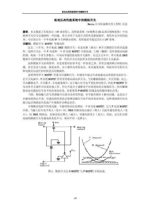
图 1: 模拟开关由 N-MOSFET 与 P-MOSFET 并联而成。
1/9
低电压高性能系统中的模拟开关
在较早的开关器件中,尤其是那些采用金属门工艺的模拟开关(如 CD4066),FET 场效 应开关需要高达 3V 的门极驱动电压才能完全导通。虽然生产厂商暗示其产品在 5V 甚至 3V 都可以工作,然而由于通态电阻平坦度差,仅适用于要求不严格场合,而非所有场合。因为, 在如此低的供电电压时,信号电平处于某些范围内时,两个 FET 均不能完全导通,结果导通 电阻平坦度很差。(见图 2)
硅门开关(如 74HC4066)在低电压时有比较好的性能。采用这种较新工艺生产的 FET 只 需不到 1V 的门极驱动电压即可导通,十分有助于改善开关的低电压工作性能。5V 电压时, 这种开关的导通电阻不大,平坦度也较好。它们甚至还可在某些 3V 场合使用。
图 2 中最下面两条曲线是另一类模拟开关的特性,它们采用了最新的硅门工艺,性能优 良。请注意开关 MAX323, 3V 工作电压时,性能比 5V 时的 74HC4066 还好一些。当工作电压 5V 时,导通电阻变化只有几欧姆。这种高性能为模拟开关开拓了新的应用领域。
如何选择模拟开关

如何选择模拟开关模拟开关模拟开关和多路转换器的作用主要是用于信号的切换。
目前集成模拟电子开关在小信号领域已成为主导产品,与以往的机械触点式电子开关相比,集成电子开关有许多优点,例如切换速率快、无抖动、耗电省、体积小、工作可靠且容易控制等。
但也有若干缺点,如导通电阻较大,输入电流容量有限,动态范围小等。
因而集成模拟开关主要使用在高速切换、要求系统体积小的场合。
在较低的频段上f<10MHz),集成模拟开关通常采用CMOS工艺制成:而在较高的频段上(f>10MHz),则广泛采用双极型晶体管工艺。
如何选择模拟开关选择开关时需考察以下指标:通道数量集成模拟开关通常包括多个通道。
通道数量对传输信号的精度和开关切换速率有直接的影响,通道数越多,寄生电容和泄漏电流就越大。
因为当选通一路时,其它阻断的通道并不是完全断开,而是处于高阻状态,会对导通通道产生泄漏电流,通道越多,漏电流越大,通道之间的干扰也越强。
泄漏电流一个理想的开关要求导通时电阻为零,断开时电阻趋于无限大,漏电流为零。
而实际开关断开时为高阻状态,漏电流不为零,常规的CMOS漏电流约1nA。
如果信号源内阻很高,传输信号是电流量,就特别需要考虑模拟开关的泄漏电流,一般希望泄漏电流越小越好。
导通电阻导通电阻的平坦度与导通电阻一致性导通电阻会损失信号,使精度降低,尤其是当开关串联的负载为低阻抗时损失更大。
应用中应根据实际情况选择导通电阻足够低的开关。
必须注意,导通电阻的值与电源电压有直接关系,通常电源电压越大,导通电阻就越小,而且导通电阻和泄漏电流是矛盾的。
要求导通电阻小,则应扩大沟道,结果会使泄漏电流增大。
导通电阻随输入电压的变化会产生波动,导通电阻平坦度是指在限定的输入电压范围内,导通电阻的最大起伏值△RON=△RONMAX—△RONMI N。
它表明导通电阻的平坦程度,△RON应该越小越好。
导通电阻一致性代表各通道导通电阻的差值,导通电阻的一致性越好,系统在采集各路信号时由开关引起的误差也就越小。
(新)高压开关事业部产品选型手册

高压开关事业部产品选型手册华仪电气股份有限公司目录一、GIS系列1、ZFW41-126/T3150-40型气体绝缘金属封闭开关设备二、断路器系列1、LW36A-72.5/126型高压交流六氟化硫断路器三、隔离开关系列1、GW4-72.5/126型户外高压交流隔离开关2、GW5系列户外高压交流隔离开关3、GW48-252型户外高压交流隔离开关4、GW49-252型户外高压交流隔离开关5、JW6-252型户外高压交流接地开关6、GW8系列中性点户外高压交流隔离开关7、GW13系列中性点户外高压交流隔离开关ZFW41-126/T3150-40型气体绝缘金属封闭开关设备一、概述ZFW41-126/T3150-40型气体绝缘金属封闭开关设备(以下简称GIS)是由华仪电气股份有限公司与德国IPT公司合作,在消化吸收国内外开关设备先进技术的基础上,利用最新的计算机模拟解析技术和试验手段进行优化设计后开发的高新技术产品。
产品适用于额定电压为110kV的电力系统中,作为发电厂、变电站和电力线路的控制、保护、切换线路及测量之用。
产品的主要特点:1、模块化设计,可靠性高,扩建方便GIS由标准化的功能模块组成,所有模块连接法兰的尺寸相同,使得各种模块可以任意组合,满足各种变电站的设计和布置要求。
合理的模块设计,将相邻间隔之间的相互影响减小到最低程度,便于以后扩建和改建。
2、体积小、重量轻采用三相共箱结构,结构紧凑、体积小,外壳采用铝合金材料,重量轻、耐腐蚀,整体采用标准化功能模块,布置灵活、维修简便、运行成本低。
3、开断能力强断路器采用第三代先进灭弧原理,具有很高的短路电流开断和关合能力,开合线路充电电流无重燃和重击穿现象,满容量电寿命达20次以上;间隔开关满足切合母线转移电流和充电电流的要求;接地开关满足关合短路电流和切合感应电流的要求。
4、绝缘水平高产品绝缘结构设计合理,整理耐受电压水平均达到或超过相应国家标准和IEC标准的要求,绝缘水平稳定可靠。
模拟开关ISL43120、ISL43121、ISL43122

低电压,单电源,双单刀单掷,单刀双掷模拟开关概述Itersil ISL43120,ISL43121,ISL43122和ISL43210是精密双向双模拟开关,工作在单一的+2.7V到+12V的电源下。
目标应用包括使用电池供电的设备,因为它有低功耗(5μW),低漏放电流(最大100pA)和快的开关速度(t ON=28ns,t OFF=20ns)。
例如,手机经常面对专用集成电路的功能性限制。
模拟输入或通用输入输出管脚数量被限制,数字几何并不适合模拟开关的性能。
这一系列器件在减少专用集成电路设计风险的同时可以实现附加的功能性。
一些最小的封装可以有效地减轻电路板的空间限制,也使Itersil最新的低电压开关成为理想的解决方案。
ISL43120,ISL43121,ISL43122是双单刀单掷器件,ISL43120有两个常开(NO)开关;ISL43121有两个常闭(NC)开关;ISL43122有一个NO和一个NC开关,可作为一个单刀双掷开关。
ISL43210是一个单刀双掷开关,很好地适用于2-to-1多路复用器的应用。
表1 特性一览5相关文献技术摘要TB363“处理和加工对湿度敏感的表面安装器件(SMDs)的准则”应用笔记AN557“模拟开关的建议测试过程”特点完全适用于10%容差的3.3V,5V和12V的电源ON电阻(R ON)………………………………… 19Ω与信道匹配的R ON (1)低电荷注入………………………………………………… 5pC(最大)单电源工作……………………………………………… +2.7V到+12V低功率消耗(P D)………………………………………… <5μW低漏放电流………………………………………………… 10nA快速开关动作-- t ON………………………………………………………… 28ns-- t OFF………………………………………………………… 20ns保证无断线(只有ISL43122/ISL43210)依据3015.7标准单次测试的最小值为2000V的静电保护可兼容TTL和CMOS采用有效地SOT-23封装无铅(符合RoHS)应用电池供电,手提和便携式设备——蜂窝式/移动式电话——寻呼机——膝上型,笔记本,掌上型PDAs 通信系统——无线电收音机,ADSL调制解调器——用户交换机,自动用户交换机测试和测量设备——超声波——CT扫描器——磁共振层析X射线摄影(MRI)——PET扫描器——逻辑和光谱分析器——心电图仪平视显示器音频和视频转换多种电路——+3V/+5V数模转换器和模数转换器——抽样和保持电路——数字滤波器——运算放大器增益转换电路——高频模拟转换——高速多路复用——积分复位电路管脚引出线图(注1)注:1. 所示开关为逻辑“0”输入引脚描述真值表≤注:逻辑“0”0.8V,逻辑“1”≥ 2.4V订购信息注:Intersil无铅产品采用特殊的无铅材料制成,模塑料/晶片的附属材料和100%无光泽锡盘引脚符合RoHS标准,兼容SnPb和无铅低温焊接操作。
IC资料-CD4051_4052_4053多路选择模拟开关
Rev 1.30 SHENZHEN CENTURY TIANCHUANG TECHNOLOGY CO.,LTD. IC设计 IC开发 国产IC 研发
CD4051/52/53
交流电参数
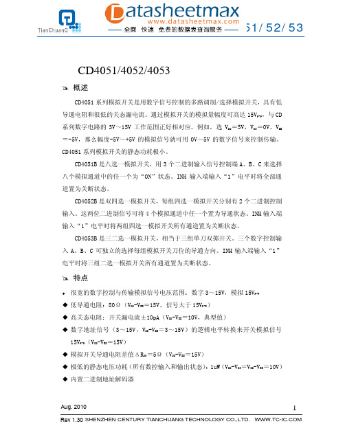
符号 tPZH tPZL 项目 从禁止到信号输出的传 输延迟时间(开启通道) 从禁止到信号输出的传 输延迟时间(关闭通道) 输入电容 输出电容 (共输入/输出) VEE=VSS=0V 旁路电容 CD4051 CPD 电源耗散电容 CD4052 CD4053 信号输入VIS和输出V OS 正弦波失真度 RL=10kΩ fIS=1kHz VIS =5Vp-p VEE=VSI =0V RL=1kΩ, VEE=0V, VIS=5VP-P, 20log10VOS/VIS=40dB RL=1kΩ,VEE=0V, VIS=5VP-P, 20log10VOS/VIS=-40 dB RL=1kΩ,VEE=0V, VIS=5VP-P, 20log10VOS/VIS=-40d B VEE=VSS=0V CL=50pF 10V 0.04 10V 40 10V 10 10V 3 5V 10V 15V VEE=VSS=0V, RL=10kΩ 在所有通道的末端 输入方波振幅10V VEE=VSS=0V CL=50pF 10V 65 5V 10V 15V 500 160 120 1000 360 240 ns mV 25 15 10 55 35 25 ns MHz MHz MHz % 条件 VEE=VSS=0V RL=1kΩ CL=50pF VEE=VSS=0V RL=1kΩ CL=50pF 控制输入 信号输入 CD4051 CD4052 CD4053 10V 10V 10V VDD 5V 10V 15V 5V 10V 15V 最小值 典型值 600 225 160 210 100 75 5 10 30 15 8 0.2 110 140 70 pF pF pF 最大值 1200 450 320 420 200 150 7.5 15 pF ns ns 单位
双路四选一模拟开关
概述
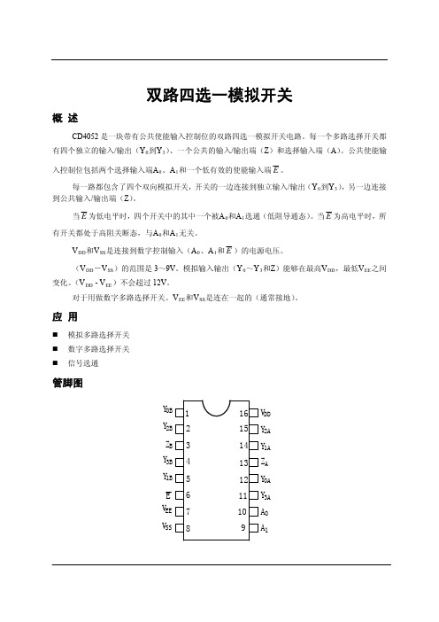
CD4052 是一块带有公共使能输入控制位的双路四选一模拟开关电路。每一个多路选择开关都 有四个独立的输入/输出(Y0到Y3)、一个公共的输入/输出端(Z)和选择输入端(A)。公共使能输
入控制位包括两个选择输入端A0、A1和一个低有效的使能输入端 E 。 每一路都包含了四个双向模拟开关,开关的一边连接到独立输入/输出(Y0到Y3),另一边连接
交流特性(VSS=VEE=0V;Tamb=25℃;输入跃变时间≤20ns)
VDD(V) 功率计算公式(μW)
一块电路的动态 功率耗散(P)
5
1300f
i
+∑(f0
C
L
)×V
2 DD
9
6100f
i
+∑(f0
C
L
)×V
2 DD
传输延时 Vis → Vos
高到低 低到高
VDD(V)
5 9
5 9
符号 t PHL t PLH
应用
模拟多路选择开关 数字多路选择开关 信号选通
管脚图
Y0B 1 Y2B 2 ZB 3 Y3B 4 Y1B 5
E6 VEE 7 VSS 8
16 VDD 15 Y2A 14 Y1A 13 ZA 12 Y0A 11 Y3A 10 A0 9 A1
管脚说明
Y0A~Y3A Y 0B ~Y 3B A0, A1
9
1
串扰,使能端或
5
—
选择端到输出
9
50
5
—
关断态
9
1
5
13
导通态频率响应
9
40
注释:Vis 是 Y 或 Z 端的输入电压,Vos 是 Y 或 Z 端的输出电压
正泰刀开关选型手册

HD、HS系列刀开关HD系列、HS系列开启式刀开关及刀形转换开关(以下简称开关)适用于交流50Hz、额定电压至380V、直流至220V,额定电流至3000A的成套配电装置中,作为不频繁地手动接通和分断交、直流电路或作隔离开关用。
其中:1.1 中央手柄式的开关主要用于动力站,不切断带有电流的电路,作为隔离开关之用。
1.2 侧方正面杠杆操作机构式开关主要用于正面操作、前面维修的开关柜中,操作机构可以在柜的两侧安装。
1.3 中央正面杠杆操作机构开关主要用于正面操作、后面维修的开关柜中,操作机构装在正前方。
1.4 侧面操作手柄式开关,主要用于动力箱中。
1.5 装有灭弧室的开关可以切断适当的电流负荷,其他系列刀开关只作隔离开关使用。
符合标准:GB 14048.3、IEC 60947-3。
□□□- □/□□□有“BX”表示旋转式操作型,无“BX”表示杠杆式操作型。
“0”表示不带灭弧装置;“1”表示有灭弧装置;对于中央手柄式:“8”表示板前接线式;“9”表示板后接线式;无则表示仅一种接线方式,即板前接线。
极数(1、2、3、4)约定发热电流(A)设计代号“11”:中央手柄式;“12”:侧方正面杠杆操作机构式;“13”:中央杠杆操作机构式;“14”:侧面手柄式;类组代号:“HD”开启式刀开关;“HS”双投转换式刀开关;表 14.1 额定工作电压为交流380V、直流220。
4.2 主要技术性能及参数(见表1)。
约定发热电流(A)机械寿命(次)电寿命(次)100100001000≤300200100001000≤300400100001000≤4006005000500≤40010005000500≤45015005000500≤45020003000300≤45030003000300≤4503.1 周围空气温度不高于+40℃,不低于-5℃。
3.2 安装地点的海拔不超过2000m。
3.3 湿度:最高温度为+40℃时,空气的相对湿度不超过50%,在较低的温度下可以允许有较高的相对湿度,例如20℃时达90%。
模拟开关(16-1)X1--ADG5206_5207_cn

2012年7月—修订版0:初始版
绝对最大额定值...........................................................................10 ESD警告....................................................................................10
引脚配置和功能描述 ..................................................................11 典型性能参数 ...............................................................................15 测试电路 ........................................................................................20 术语.................................................................................................22 应用信息 ........................................................................................23
Ω (最大值) Ω (典型值) Ω (最大值)
nA (典型值)
nA (最大值) nA (典型值)
nA (典型值) nA (最大值) nA (典型值) nA (最大值) nA (典型值)
nA (典型值) nA (最大值) nA (典型值) nA (最大值) nA (典型值)
智能开关选用手册_办公篇
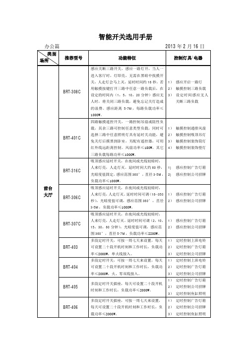
智能开关选用手册接待室BRT-308C感应关断三路开关,感应一路灯开,当人一进入客厅时,灯即亮,无需在黑暗中找摸开关,人走灯会马上灭,延时时间约16秒,若用触摸按键打开三路中任意一路负载后,设定的时间内(1,5,10,20分钟)感应无人时,将关闭三路负载,避免忘记关灯造成的浪费。
感应距离5-7M,每路负载功率≤1000W。
1)感应开一路灯或负载2)触摸控制三路灯或负载3)感应无人关断三路灯或负载BRT-309吸顶感应关断器,在设定时间内(1,5,10,20分钟)感应无人时,将关闭负载或照明灯具,避免忘记关闭负载或灯所造成的浪费,感应范围360°,直径5-7M,负载功率≤2200W。
1)感应无人关断照明灯或通排风设备BRT-310吸顶感应关断遥控器,在设定时间内(1,5,10,20分钟)感应无人时,将遥控关闭空调,电视,音响等具遥控功能的设备,避免忘记关设备所造成的浪费,感应范围360°,直径5-7M,输入电压为AC 220-240/50HZ。
1)感应无人关闭空调或具有红外遥控功能的其它设备BRT-311吸顶感应关断遥控器,在设定时间内(1,5,10,20分钟)感应无人时,将遥控关闭空调,电视,音响等具遥控功能的设备,避免忘记关设备所造成的浪费,感应范围360°,直径5-7M,输入电压为DC24V,配DC24V适配器。
1)感应无人关闭空调或具有红外遥控功能的其它设备办公大厅BRT-401A四路触摸遥控开关,一路控制吊扇或阻性负载,其余三路可控制任意类型负载,同时可选择三路中任意照明灯具有延时关功能,避免关灯后摸黑到卧室,另配有遥控器,可用红外线远距离控制。
风扇功率≤150W,其它三路负载每路功率≤1000W。
1)控制一路吊扇或阻性照明灯具2)控制其它三路任意照明灯具BRT-308C感应关断三路开关,感应一路灯开,当人一进入客厅时,灯即亮,无需在黑暗中找摸开关,人走灯会马上灭,延时时间约16秒,若用触摸按键打开三路中任意一路灯后,在设定的时间内(1,5,10,20分钟)感应无人时,将关闭三路负载,避免忘记关灯造成的浪费。
常用模拟开关

常用模拟开关关在电路中起接通信号或断开信号的作用。
最常见的可控开关是继电器,当给驱动继电器的驱动电路加高电平或低电平时,继电器就吸合或释放,其触点接通或断开电路。
CMOS模拟开关是一种可控开关,它不象继电器那样可以用在大电流、高电压场合,只适于处理幅度不超过其工作电压、电流较小的模拟或数字信号。
一、常用CMOS模拟开关引脚功能和工作原理1.四双向模拟开关CD4066CD4066的引脚功能如图1所示。
每个封装内部有4个独立的模拟开关,每个模拟开关有输入、输出、控制三个端子,其中输入端和输出端可互换。
当控制端加高电平时,开关导通;当控制端加低电平时开关截止。
模拟开关导通时,导通电阻为几十欧姆;模拟开关截止时,呈现很高的阻抗,可以看成为开路。
模拟开关可传输数字信号和模拟信号,可传输的模拟信号的上限频率为40MHz。
各开关间的串扰很小,典型值为-50dB。
图1 CD4066的引脚功能2.单八路模拟开关CD4051CD4051引脚功能见图2。
CD4051相当于一个单刀八掷开关,开关接通哪一通道,由输入的3位地址码ABC来决定。
其真值表见表1。
“INH”是禁止端,当“INH”=1时,各通道均不接通。
此外,CD4051还设有另外一个电源端VEE,以作为电平位移时使用,从而使得通常在单组电源供电条件下工作的CMOS电路所提供的数字信号能直接控制这种多路开关,并使这种多路开关可传输峰-峰值达15V的交流信号。
例如,若模拟开关的供电电源VDD=+5V,VSS=0V,当VEE=-5V时,只要对此模拟开关施加0~5V的数字控制信号,就可控制幅度范围为-5V~+5V的模拟信号。
图2 CD4051引脚功能表1 CD4051真值表3.双四路模拟开关CD4052CD4052的引脚功能见图3。
CD4052相当于一个双刀四掷开关,具体接通哪一通道,由输入地址码AB来决定。
其真值表见表2。
图3 CD4052的引脚功能表2 CD4052真值表4.三组二路模拟开关CD4053CD4053的引脚功能见图4。
omron限位开关选型手册

—
—
—
—
600V —
AC-15
10A
AC-15
10A
AC-15
5A
AC-15
5A
6A
3A
—
—
—
—
6A
3A
1.9A 1.5A 1.4A 1.2A
3A
—
—
—
—
—
3A
1.5A
—
—
—
—
AC-15
5A
3A
1.5A 0.95A 0.75A 0.72A 0.6A
AC-15
2.5A
1.5A
—
—
—
—
—
AC-15
2.5A
动作速度及动作次数动作距离操作体凸轮挡块的角度环境异物腐蚀性气体用途电气方面电气回路的开闭寿命长低电力消费短路保护装置带保险丝低噪音的场合高规格高电压场合行业应用在以下各行各业得到广泛应用机床注塑机汽车厂各种流水线立体停车库各种环保设备防灾设备建筑机械机械方面常闭nc触点需带有强制断开机构特殊环境油水药品要求极高的机械重复精度视觉上能判断动作状态旋转式操作头方向式操作头限位开关触头块的运行概述动作特性图快速动作型按动式回转式慢速动作型按动式回转式符合jis4508标准的术语符合jis4508标准的术语欧洲术语保证可靠断开的触点ab专用名称无专用名称ttptotrpopfpttp总行程接近行程位移差超出行程释放位置动作位置起始位置总行程位置ttpptrpmd表示导通正行程逆行程2122131421221314正行程逆行程21221314ttpfp欧洲术语常开触点的触发和复位点ttttp总行程起始位置总行程位置omron限位开关概述触点类型触点接线图型式zazbc仅适于型式zb仅适于型式zaomron型式za型式zb相同极性电路混合电压型式c交替动作iec94751nemajis型式符号说明型式符号说明型式符号说明zazb相同极性仅适于相同极性电气隔离限位开关术语快速动作型慢速动作型开关切换为瞬动型型式comron速动触点co未动状态接近行程未动状态触头状态的改变肯定断开强制断开机构incino接点接点速度与驱动杆的运动速度连动慢速动作incino之强制断开机构型式za未动状态示意触发状态示意未动状态触发状态型式zb型式zb触发状态触点额定值的规格iec94751使用类别iec94751限位开关触点的额定值概述omron电流类型交流直流类型ac12ac13ac14ac15dc12dc13dc14典型的应用控制光耦隔离的阻性和固态负载控制变压器隔离的固态负载控制小型电磁负载72va控制电磁负载72va控制光耦隔离的阻性和固态负载控制电磁负载控制电路中带有节能电阻的电磁负载t095cosdcac0906503031ms300ms最大15ms095到达稳态电流95的时间规格a150a300a600b150b300b600c150c300c600d150d300e150使用类别ac15ac15ac15ac15ac15ac15ac15ac15ac15ac14ac14ac14约定热电流10a6a6a6a3a3a3a19a15a1
通用模拟开关说明书 - TS3A5018
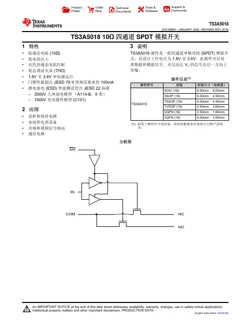
NC COM INNOENProductFolder OrderNow TechnicalDocuments Tools &SoftwareSupport &CommunityTS3A5018ZHCSIB0H –JANUARY 2005–REVISED MAY 2018TS3A501810Ω四通道SPDT 模拟开关1特性•低通态电阻(10Ω)•低电荷注入•出色的通态电阻匹配•低总谐波失真(THD)• 1.8V 至3.6V 单电源运行•闩锁性能超出JESD 78II 类规范要求的100mA •静电放电(ESD)性能测试符合JESD 22标准–2000V 人体放电模型(A114-B ,II 类)–1000V 充电器件模型(C101)2应用•采样和保持电路•电池供电类设备•音频和视频信号路由•通信电路3说明TS3A5018器件是一款四通道单极双投(SPDT)模拟开关,其设计工作电压为1.8V 至3.6V 。
此器件可以处理数据和模拟信号,并且高达V +的信号在任一方向上传输。
器件信息(1)器件型号封装封装尺寸(标称值)TS3A5018SOIC (16)9.90mm ×6.00mm SSOP (16)6.00mm ×4.90mm TSSOP (16) 5.00mm ×4.40mm TVSOP (16) 4.40mm ×3.60mm UQFN (16) 2.50mm ×1.80mm VQFN (16)4.00mm ×3.50mm(1)如需了解所有可用封装,请参阅数据表末尾的可订购产品附录。
方框图TS3A5018ZHCSIB0H–JANUARY2005–REVISED 目录1特性 (1)2应用 (1)3说明 (1)4修订历史记录 (2)5Pin Configuration and Functions (3)6Specifications (4)6.1Absolute Maximum Ratings (4)6.2ESD Ratings (4)6.3Recommended Operating Conditions (4)6.4Thermal Information (4)6.5Electrical Characteristics for3.3-V Supply (5)6.6Electrical Characteristics for2.5-V Supply (6)6.7Electrical Characteristics for2.1-V Supply (7)6.8Electrical Characteristics for1.8-V Supply (7)6.9Switching Characteristics for3.3-V Supply (8)6.10Switching Characteristics for2.5-V Supply (8)6.11Switching Characteristics for1.8-V Supply (9)6.12Typical Characteristics (10)7Parameter Measurement Information (13)8Detailed Description (17)8.1Overview (17)8.2Functional Block Diagram(Each Switch) (17)8.3Feature Description (17)8.4Device Functional Modes (17)9Application and Implementation (18)9.1Application Information (18)9.2Typical Application (18)10Power Supply Recommendations (19)11Layout (19)11.1Layout Guidelines (19)11.2Layout Example (19)12器件和文档支持 (20)12.1器件支持 (20)12.2文档支持 (20)12.3接收文档更新通知 (21)12.4社区资源 (21)12.5商标 (21)12.6静电放电警告 (21)12.7术语表 (21)13机械、封装和可订购信息 (21)4修订历史记录注:之前版本的页码可能与当前版本有所不同。
模拟开关指南

模拟开关指南TI 信号开关产品线包括高性能、低功耗的数字、模拟及专业开关。
£ PinoutsSPSTCOM GNDINV+NO 12345COM GNDINV+NC 12345TS5A1066, TS5A3166TS5A3167TS5A4596TS5A4597COM GNDINV+NO12345COM GNDINV+NC12345COMGNDNOV+IN 12345COMGNDNCV+IN 12345TS5A4594, TS12A4514, TS12A4516TS5A4595, TS12A4515, TS12A4517TS12A4514, TS12A4516N.C.N.C.V +COM GND IN N.C.NO 76582341N.C.N.C.V +COM GND IN N.C.NC 76582341TS12A4515, TS12A4517SPST x 4COM1NO2COM2IN2NO112345IN26IN27IN1IN4NO4COM4V +1413121110COM39NO38TS3A4751, TS12A44514COM1NC2COM2IN2NO112345IN36GND7IN1IN4NC4COM4V +1413121110COM39NO38TS12A44513COM1NC2COM2IN2NC112345IN36GND7IN1IN4NC4COM4V +1413121110COM39NC38TS12A44515引出脚配置£SP3TSP4T x 2NO1NO2GNDIN1V +IN2NO0COM Logic Control12348765TS5A3357, TS5A3359101171S 2123451615141312IN 21S 41S 3IN1V +2S 42S 361D 1S 12S 22S 18GND92D1EN 2EN Logic Control Logic ControlTS3A5017SPDT x 4SPDT x 2Input SelectShunt SwitchIN2IN1COM2COM1NC2NC1NO2OUT+OUT+OUT–OUT–NO1TS5A22364Audio Source 1Audio Source 28-SpeakerΩ12345109876NO2COM2NC2IN2V +NO1COM1NC1IN1GNDNO1GND NO2IN2IN1COM1NC1NC2COM2V+12345109876TS5A23157, TS5A23159, TS5A2316010117NC2123451615141312NC1NO1COM1NC4V +NO4COM46COM2NO2NC3NO38GND9COM3IN EN LogicControlTS3A5018Analog Switches PinoutsA4DCB A4321A3A2B4B3B2B1C4C3C2C1D4D3D2D1A1432 1 D /MIC_PRESENTTIP_SENSE MICp MICnC RING2 GND (1) VDD (1) RING2_SENSE B SLEEVE GND (1) VDD (1) SLEEVE_SENSEADET_TRIGGERADDR_SEL SDA SCLTSA225E12A B C12A SELV+ BMIC SLEEVECGNDRING2TS3A26746EYZP Package (Top View)模拟开关引出脚配置2x2 Crosspoint Switch for Audio Applications TS3A26746EGet samples, data sheets and app reports at: /sc/device/ts3a26746eKey Featuresr 4VQFSJPS 1433 QFSGPSNBODF (-75 dB)r $POUSPM JOQVU JT 7 MPHJD compatibler &4% QFSGPSNBODF 4-&&7& 3*/( o ±8-kV contact discharge (IEC 61000-4-2)r CVNQ NN QJUDI $41 package (1.45 x 0.95 x 0.5 mm)Applications r $FMMVMBS QIPOFT r %JHJUBM TUJMM DBNFSBT r 1%"Tr 1PSUBCMF JOTUSVNFOUBUJPOr 1PSUBCMF OBWJHBUJPO EFWJDFTThe TS3A26746E is a 2 × 2 cross-point switch that is used to interchange theground and MIC connections on a headphone connector. The ground switch has an ultra low r ON of <0.1 Ω to minimize voltage drop across it, preventing undesired increases in headphone ground reference voltage. The switch state is controlled via the SEL input. When SEL=High, GND is connected to RING2 andMIC is connected to SLEEVE. When SEL=Low, GND is connected to SLEEVE and MIC is connected to RING2. An internal 100k pull-up resistor on the SELinput sets the default state of the switch. This device effectively switches the GND and MIC lines to the appropriate coordinates with minimal signal distortion and power loss.Typical application block diagram.V +MICRIGHT LEFTTIPRING 1RING 2100 KΩSLEEVEACCESSORY DATAMIC BIAS12A B C12A SELV+ BMIC SLEEVECGNDRING2YZP Package(Top View)面向音频应用的 2 x 2 交叉点开关TS3A26746E YZP 封装(顶视图)主要特点 出众的 PSRR 性能 (-75 dB) 控制输入可兼容 1.8 V 逻辑 ESD 性能(SLEEVE 、RING2) ±8k V 接触放电 (IEC 61000-4-2) 6 焊凸、0.5 mm 间距 CSP 封装 (1.45 x 0.95 x 0.5 mm)应用蜂窝电话 数码相机个人数字助理 (PDA) 便携式仪表 便携式导航设备TS3A26746E 是一款2 x 2 交叉点开关,用于切换头戴式耳机连接器上的接地和 MIC接线。
KM-KZ系列开关柜智能操显装置产品选型手册说明书

四、KM-KZ 接线端子图
四、KM-KZ-5接线端子图
具有动态模拟图、柜内温湿度数字显示、带电显示及闭锁、智能语音防误提示功能,还可选择配置
数字通讯、人体感应功能,并且可根据用户的控制要求在装置上安装对应的操控转换开关(包括储能开关、远方/就
地转换开关、分合闸转换开关)。
温湿度控制数字化后,用户可根据需要自行设置加热 / 除湿输出的上下限以及过热排风的
二、外形尺寸
四、KM-KZ-6接线端子图
不仅具有动态模拟图、柜内温湿度数字显示、带电显示及闭锁、智能语音防误提示功能、操控转换开关
数字通讯等功能;另与外置无线测温传感器配合使用,
可在线测量母排、断路器触头、电缆搭接头等多处实时温度等功能。
二、外形尺寸。
常熟开关CM2选型手册
Ambient temperature:-5℃ ~+40℃ and the average in 24 hours below +35.
Elevation≤2000m. Relative humidity: not exceed 50% at the maximum ambient temperature of +40℃ , but higher relative humidity at the lower temperature, for example, 90% at 20℃ (Relative humidity of the humid tropical area breakers isn't exceeding 95% at the temperature of +25℃). Special measures should be taken considering the dews on product surface due to temperature change. Pollution protection :3 grade. Installing categories: III for the main circuit and under-voltage release of the breakers, and II for other auxiliary and control circuits. The breakers are suitable in electromagnic environment A. The breakers used in humid tropical(TH) area can work normally without influence of humid air, salt fog and milder. There must be not any explosive medium, and there must be not any gas which would corrode metal or any conducting dust which would destroy the insulation. The place would not be invaded by rain and snow.
Eaton产品指南:模拟和数字模拟开关、闪电开关、脉冲、周期、假期和晨昏程序版本说明书

Modular Switches and Twilight Switches Product Guide • Analogue and Digital• Pulse, cycle, holidays and astronomical program versions • Compact, modular design• Twilight switches including external light sensorHigh accuracy time control and switching made easyHydraulics Powering business worldwideNext generation transportationEaton is driving the development of newtechnologies – from hybriddrivetrains and emission control systems to advanced engine components – that reduce fuel consumption and emissions in trucks and cars.Higher expectationsWe continue to expand our aerospace solutions and services to meet the needs of new aviation platforms,including the high-flying light jet and very light jet markets.Building on our strengths Our hydraulics business combines localized service and support with an innovative portfolio of fluid powersolutions to answer the needs of global infrastructure projects, including locks, canals and dams.Powering Greener Buildings and BusinessesEaton’s Electrical Group is a leading provider of power quality, distribution and control solutions that increase energy efficiency and improve power quality, safety and reliability. Our solutions offer a growing portfolio of “green” products and services, such as energy audits and real-time energy consumption monitoring.Eaton’s Uninterruptible Power Supplies (UPS), variable-speed drives and lighting controls help conserve energy and increase efficiency.Eaton delivers the power inside hundreds of products that are answering the demands of today’s fast changing world.We help our customers worldwide manage the power they need for buildings, aircraft, trucks, cars, machinery and entire businesses. And we do it in a way that consumes fewer resources.AutomotiveAerospaceElectricalTruckHydraulics3CA081003EN - January 2013 MODULAR TIMERS AND TWILIGHT SWITCHES Modular timers and twilight switches1Switches and twilight switches . . . . . . . . . . . . . . . . . . . . . . . . . . . . . . . . . . . . . . . . . . . . 4Universal declaration type coding . . . . . . . . . . . . . . . . . . . . . . . . . . . . . . . . . . . . . . . . . . . . . . . . . . . . 42Analogue time switches . . . . . . . . . . . . . . . . . . . . . . . . . . . . . . . . . . . . . . . . . . . . . . . . . . 5Analogue time switches - 50 Hz mains synchronised . . . . . . . . . . . . . . . . . . . . . . . . . . . . . . . . . . . . . 5Analogue time switches - Quartz controlled . . . . . . . . . . . . . . . . . . . . . . . . . . . . . . . . .. . . . . . . . . . . . 5Analogue weekly time switches - Quartz controlled . . . . . . . . . . . . . . . . . . . . . . . . . . . . . . . . . . . . . . . 53Digital time switches with weekly programme . . . . . . . . . . . . . . . . . . . . . . . . . . . . . . . 6Digital weekly time switches, 1 channel . . . . . . . . . . . . . . . . . . . . . . . . . . . . . . . . . . . . . . . . . . . . . . . . . 6Digital weekly time switches, 2 channel . . . . . . . . . . . . . . . . . . . . . . . . . . . . . . . . . . . . . . . . . . . . . . . . . 64Twilight switches and time switches for DIN rail mounting . . . . . . . . . . . . . . . . .. . . . 8Twilight switches for DIN rail mounting . . . . . . . . . . . . . . . . . . . . . . . . . . . . . . . . . . . . . . . . . . . . . . . 8Combination twilight switch with timer . . . . . . . . . . . . . . . . . . . . . . . . . . . . . . . . . . . . . . . . . . . . . . . . 85Twilight switch and combination timer for surface mounting . . . . . . . . . . . .. . . . . .. . 9Twilight switch for surface mounting . . . . . . . . . . . . . . . . . . . . . . . . . . . . . . . . . . . . . . . . . . . . . . . . . . 96Accessories . . . . . . . . . . . . . . . . . . . . . . . . . . . . . . . . . . . . . . . . . . . . . . . . . . . . . . . . . . . . . 10Antenna for DCF signal reception . . . . . . . . . . . . . . . . . . . . . . . . . . . . . . . . . . . . . . . . . . . . . . . . . ... 10Antenna including power supply for GPS signal reception . . . . . . . . . . . . . . . . . . . . . . . . . . . . . . . . . 10Programming software kit including memory card . . . . . . . . . . . . . . . . . . . . . . . . . . . . . . . . . . . . . . ..1014SWITCHCLOCK AND LIGHT SWITCHES CA081003EN - January 2013Switches and twilight switches1Technical characteristics (depending on type)Modular design.Analogue and digital timers.Time adjustment by 50 Hz net, quartz control, DCF 1) or GPS signal reception 2).Manual override switching function.Power reserve for all quartz and DCF or GPS driven switches. Remote light sensor for twilight switching.Benefits Easily programmable on front of device.Computer aided programming software available.Compact 18 mm design for restricted space opportunities.Separate IP40 covers are available for direct wall mounting.High level of accuracy.Automatic summer and winter time adjustment.Holiday & Random program settings.High power reserve up to 10 years.Notes:1)Automatic calculation of sunrise and sunset times throughout the year, including the possibility of astro times + / -2 hour shift.2)The DCF-signal can only be received within a 1000 km radius.Universal declaration type codingType coding - analogue switchesType coding - digital switchesTS Q D 1NO TS D W 1CO -TS S D 1NO TS D W 2CO -TS Q D 1CO TS D W 1CO A TS S D 1CO TS D W 1CO DG TSQW1COTSDW1COMINTS =SwitchQ / S = Quartz / 50 Hz net-synchronisation D / W=Day / week programme1NO / 1CO= Create / change (contact configuration)TS =Switch D =DigitalW=Week programme1CO / 2CO =Exchange / 2 x changeover (contact configuration)A =AstroclockDG =DCF or GPS controlledMIN=Compact 18mm design versionType coding - digital switches and accessories Type coding - twilight switchesTS A DCF SR S D 1NO -TS A GPSKIT SR S W 1NO -TS A MEMKIT SR C D 1CO -TSAMEMSRSD1COWTS = Switch A =Accessory DCF =DCF-antennaGPSKIT=Antenna for GPS signal reception including power supplyMEMKIT =Programming software kit MEM = MemorySR =Twilight switchS / C =With or without sensorD / W=DIN rail mounting / surface mounting 1NO / 1CO =Create / change (contact configuration)W=Wide adjustable sensitivity (2 - 50000 lux)Timers & Twilight Switches are applied in any residential orcommercial buildings wherever automatic control is required on predefined times and/or depending on daylight intensity. The Eaton range comprises of a wide variety of differentproducts which include analogue Timers, digital Timers, Twilight Switches and Staircase Timers.These Timers can either be controlled by a 50 Hz net-synchronisation, quartz control and time synchronisation or usingthe DCF signal or GPS antenna, which guarantees 100% accuracy at all times. Except for net-synchronised timers all units do have self power reserve to secure the time setting and programstorage in case a power interruption does occur.Dedicated computer software and memory cards are available tosupport the programming of our most advanced timers.Automatic summer and winter time, holiday and randomswitching programs complete the functionality of our range.Twilight Switches are supplied with a remote light sensor, which can be easily installed on the outside wall where the required light intensity threshold can be simply adjusted on the modular device itself.5CA081003EN - January 2013 ANALOGUE DAY AND WEEK TIMERS Analogue day and week timers2DIN-modular2Technical characteristics (dependant of type)●Supply voltage 230 V / 50 - 60 Hz (50 Hz for just synchronised versions)● 50 Hz-mains synchronised or Quartz controlled.● Daily or weekly programme.● Manual override switching function.●Compact 18mm design for restricted space opportunities.See page 10 for accessoriesSee page 12 for the technical data for analogue day and 7 day timers.167391Standard version167389■18 mm compact design167390■Standard version167388■18 mm compact design167392■Standard versionAnalogue time switches - 50 Hz mains synchronisedProgram rangeTypeChannelsContact configuration Power reserve Min. cycling timeWidth Type QPCEatonlist numberDay 50 Hz-net 1CO -15 min.52.5 mm TSSD1CO 1167391Analogue time switches - 50 Hz mains synchronisedDay 50 Hz-net 1NO -15 min.17.5mm TSSD1NO 1167389Analogue time switches - Quartz controlledDay Quartz 1200 hrs 15 min.52.5 mm TSQD1CO 1167390Analogue time switches - Quartz controlledDay Quartz 1NO 3 yrs 15 min.17.5 mm TSQD1NO 1167388Analogue weekly timer switches - Quartz controlledWeek Quartz 1CO 200 hrs 2 hrs 52.5 mm TSQW1CO 1167392■Program rangeTypeChannelsContact configuration Power reserve Min. cycling timeWidth Type QPCEatonlist numberCO Program rangeTypeChannelsContact configuration Power reserve Min. cycling timeWidth Type QPCEatonlist numberProgram rangeTypeChannelsContact configuration Power reserve Min. cycling timeWidth Type QPCEatonlist numberProgramrangeTypeChannelsContact configuration Power reserve Min. cycling timeWidth Type QPCEatonlist number36DIGITAL TIME SWITCHES WITH WEEKLY PROGRAMME CA081003EN - January 2013Digital time switches with weekly programme3DIN-modularTechnical characteristics● Operating voltage 230 V / 50 - 60 Hz.● 1 or 2 channel.● Quartz controlled.● 3 to 10 year power reserve.● Weekly programme.● Manual ON (and depending on type OFF) switching.●Text-oriented user guidance in display.● Display back light (switchable).● Compact 18mm design for restricted space.● Automatic summer and winter adjustment.● Holiday programme.● Zero crossing switching relay for longer life.● Integrated operating hour counter.●TSDW1CO, TSDW2CO, TSDW1COA, TSDW1CODG:Interface for memory.See page 10 for accessoriesSee page 14 for the technical details of digital weekly time switches167379■Standard version167383■1TE wide version167382■1TE wide version167381■AstronomicalDigital weekly time switches, 1 channelWeekQuartz 1 CO 10 year 1 min.5635.8 mm TSDW1CO 1167379Digital weekly time switches, 1 channelProgramrange TypeChannels Contactconfiguration Power reserve Minimum switching Programming steps WidthType QCPEatonlist numberWeekQuartz 1CO 3 year 1 min.2817.5 mm TSDW1COMIN 1167383Digital weekly time switches, 1 channelWeekQuartz,DCF / GPS1CO 10 year 1 sec.8435.8 mm TSDW1CODG 1167382Digital weekly time switches, 1 channelWeekQuartz with astronomical1CO 10 year 1 min.4236 mm TSDW1COA 1Program range TypeChannels Contact configuration Powerreserve Minimum switching Programming steps WidthType QCPEatonlist numberProgram range TypeChannels Contact configuration Powerreserve Minimum switching Programming steps WidthType QCPEatonlist numberProgram range TypeChannels Contact configuration Powerreserve Minimum switching Programming steps WidthType QCPEatonlist number7Digital week timers3DIN-modular 3167380■Standard versionDigital week timers, 2 channelsProgram rangeTypeChannelsContactconfiguration Power reserve Power reserve Min. cycling timeWidth TypeQPCEatonlist numberWeek Quartz 2 2 x CO 10 year 1 min.5635.8 mm TSDW2CO 1167380CA081003EN - January 2013 DIGITAL TIME SWITCHES WITH WEEKLY PROGRAMME48TWILIGHT SWITCHES WITH TIME SWITCH FOR DIN-RAIL MOUNTING CA081003EN - January 2013Twilight switches with time switch for DIN-rail mounting4Including external light sensorTechnical characteristics● Operating voltage 220 - 240 V / 50 - 60 Hz.● 1 channel.● Controlled by external light sensor (supplied).●Built-in time delay included for unwanted switching e.g. due tocar lamp influences (adjustable to type SRSD1COW and SRCD1CO).● Switching status indication.●Adjustable light intensity level.SRCD1CO● Manual ON and OFF switching.● Back lit display.● Automatic summer and winter time adjustment.● Holiday programme.● Zero crossing switching relay for longer life.● Integrated operating hour counter.● Memory interface.●Test function.See page 10 for accessoriesSee page 16 for the technical details for twilight switch (and combination with timer).167375I 18 mm compact design167378I Advanced version, 1 channel167377ICombined versionTwilight switches for DIN rail mountingDescription Channels Adjustable sensitivityContactconfigurationWidth Type QPCEatonlist numberTwilight switch with light sensor 12 - 100 lux NO 17.5 mm SRSD1NO 1167375Twilight switches for DIN rail mountingTwilight switch with light sensor 1 2 - 50.000 lux CO 54 mm SRSD1COW 1167378Twilight switches for DIN rail mountingWeek 1 2 - 2.000 lux CO 72 mm SRCD1CO 1167377Description Channels Adjustable sensitivityContactconfigurationWidth Type QPCEatonlist numberProgram range Channels Adjustable sensitivityContactconfigurationWidth Type QPCEatonlist number9CA081003EN - January 2013 COMBINED DIGITAL WEEK TIMER AND TWILIGHT SWITCH Combined digital week timer and twilight switch5Integrated light sensor5Technical characteristics● Operating voltage 220 - 230 V / 50 - 60 Hz.● 1 channel.● Integrated light sensor.●Time delay included for unwanted switching (e.g. due to car lamp influences).● Back or bottom cable entry.● Adjustable light intensity on the outside.● Large light level (180 degrees).● Test button.● Adjustable light intensity level.●Degree of protection: IP55.See page 10 for accessories.See page 16 for the technical details for timer and twilight switches.167376I1 channelTwilight switch for surface mountingProgram rangeChannels Adjustable sensitivityContactconfigurationWidth Type QPCEatonlist numberWeek 1 2 - 2.000 lux CO 85 mm SRSW1NO 1 167376610ACCESSORIES CA081003EN - January 2013Accessories6For timers and twilight switches167384GBy using DCF reception 100% accuracy is obtained. A DCF antenna is required to be mounted on an outside wall. The DCF signal reception is only operable when the timer is connected to the remote DCF antenna and fed by a DCF power supply.GDCF antenna for digital TSDW1CODG.167385GAntenna includes power supply for TSDW1CODG.167386GFor SRCD1CO, TSDW1CO, TSDW2CO, TSDW1COA, TSDW1CODG.Antenna for DCF signal receptionDescriptionTypeQPCEatonlist numberDCF-antenna TSADCF 1167384Antenna includes power supply for GPS signal reception Antenna for GPS signal reception, includes power supply TSAGPSKIT 1167385Programming software kitProgramming software kit including adaptor cable, software and memory card TSAMEMKIT 1167386Memory card TSAMEM 1167387DescriptionTypeQPCEatonlist numberDescriptionTypeQPCEatonlist numberTechnical data7Technical data. . . . . . . . . . . . . . . . . . . . . . . . . . . . . . . . . . . . . . . . . . . . . . . . . . . . 12 Analogue day and week timers, technical data . . . . . . . . . . . . . . . . . . . . . . . . . . . . . . . . . . 12Analogue day and week timers, dimensional drawings. . . . . . . . . . . . . . . . . . . . . . . . . . . . . 13Analogue daily and weekly timers, wiring diagrams. . . . . . . . . . . . . . . . . . . . . . . . . . . . . . . 13Digital weekly timers, technical data . . . . . . . . . . . . . . . . . . . . . . . . . . . . . . . . . . . . . . . . . 14Digital weekly timers, dimensional drawings. . . . . . . . . . . . . . . . . . . . . . . . . . . . . . . . . . . . 15Digital weekly timers, wiring diagrams. . . . . . . . . . . . . . . . . . . . . . . . . . . . . . . . . . . . . . . . 15Twilight switches and combination with timer, technical data . . . . . . . . . . . . . . . . . . . . . . 16Twilight switches and combination with timer, dimensional drawings . . . . . . . . . . . . . . . . . 17Twilight switches and combination with timer, wiring diagrams . . . . . . . . . . . . . . . . . . . . . 17CA081003EN - January 2013 TECHNICAL DATA11712TECHNICAL DATA CA081003EN - January 2013Technical data7Analogue day and week timers, technical data Analogue time switchesTSSD1COTSSD1NOTSQW1COTSQD1COTSQD1NOGeneralOperating voltage 110 - 230V AC 230 V AC 110 - 230 V AC 110 - 230 V AC 230 - 240 V AC Frequency 50 Hz 50 Hz 50 - 60 Hz 50 - 60 Hz 50 - 60 Hz Stand-by power 0.9 W 0.9 W 0.5 W 0.5 W 0.5 W Time control Net Net Quartz Quartz Quartz Accuracy Volgens net Volgens net ± 1 sec. / day ± 1 sec. / day ± 1 sec. / day Power reserve--200 hrs /100 hrs at 110 V 200 hrs /100 hrs at 110 V ±3 days Battery type--NiMH NiMH NiMH Degree of protection (EN 60529)IP20IP20IP20IP20IP20Ambient temperature -20∞C...+55 ∞C -25 ∞C...+50 ∞C -20 ∞C...+55 ∞C -20 ∞C...+55 ∞C -10 ∞C...+55 ∞C Protection class (EN 60730-1)IIIIIIIIIISwitching contact(s)Type of switching contact1 x CO 1 x NO 1 x CO 1 x CO 1 x CO Switching capacity at 250 V~, cos = 1 16 A 16 A 16 A 16 A 16 A Switching capacity at 250 V~, cos = 0,6A4 A4 A4 A4 AProgramming featuresPeriod of program Day Day Week Day Day Number of channels11111Minimum cycle time 15 min.15 min. 2 hrs 15 min.15 min.Programmable Programmable 15 min.Programmable 15 min.Programmable 2 hrs Programmable 15 min.Programmable 15 min.Program steps9696849696Manual / Hand / Permanent switching 1)On, Off, Auto On, Off, Auto On, Off, Auto On, Off, Auto On, Off, Auto Switching status indicationxxxxxDimensions and weightNumber of module width 31331DimensionsWidth 52.5 mm 17.5 mm 52.5 mm 52.5 mm 17.5 mm Height 90 mm 90 mm 90 mm 90 mm 90 mm Depth65.5 mm 65.5 mm 65.5 mm 65.5 mm 65.5 mm MountingDIN-railDIN-railDIN-railDIN-railDIN-railTerminalsTerminal screw sizeM3.5M3.5M3.5M3.5M3.51)RemarkON = Permanent ON OFF = Permanant OFFHands = ON or OFF. valid until next program cycle overrules Auto = According program4Technical data77 Analogue daily and weekly timers, dimensional drawingsAnalogue daily and weekly time switches, wiring diagrams.....13CA081003EN - January 2013 TECHNICAL DATA714TECHNICAL DATA CA081003EN - JanuaryTechnical data7Digital week timers, technical detailsDigital timers - week programmeTSDW1CO TSDW1COMIN TSDW2CO TSDW1COA TSDW1CODGGeneralNominal operating voltage 230 - 240 V AC 230 V AC 230 - 240 V AC 230 - 240 V AC 230 - 240 V AC Frequency 50 - 60 Hz 50 - 60 Hz 50 - 60 Hz 50 - 60 Hz 50 - 60 Hz Stand-by power 0,8 W 0,4 W 0,8 W 0,8 W 1,4 WTime base control 1)QuartzQuartz QuartzAstroQuartz of DCF / GPS Accuracy ± 0,5 sec. / day ± 1 sec. / day ± 0,5 sec. / day ± 0,5 sec. / day ± 0,5 sec. / day Power reserve 10 year 3 year 10 year 10 year 10 year Type of batteryLithium Lithium (exchangeable)LithiumLithium Lithium Protection class (acc. EN 60529)IP20IP20IP20IP20IP20Permissible ambient temperature-30 ∞C...+55 ∞C-10 ∞C...+50 ∞C -30 ∞C...+55 ∞C -30 ∞C...+55 ∞C -30 ∞C...+55 ∞C Protection class at proper installation (acc. EN 60730-1)IIIIIIIIIISwitching contact(s)Type of switching contact 1 x CO 1 x CO 2 x CO 1 x CO 1 x CO Switching capacity at 250 V~, cos ϕ= 116 A 16 A 16 A 16 A 16 A Switching capacity bij 250 V~, cos ϕ = 0,610 A6 A10 A10 A10 ASwitching capacity for lighting :-Incandescent lamp 2600 W 1000 W 2600 W 2600 W 2600 W -Halogen lamp2600 W1000 W2600 W2600 W2600 WProgramming featuresPeriod of programme Week Week Week Week Week Number of channels 11211Minimum switching capacity 10 mA -10 mA 10 mA -Minimum cycle time1 min. 1 min. 1 min. 1 min. 1 sec.Maximum programming steps in memory 5628565484Summer / wintertime automatic(or manual on/off)Yes Yes Yes Yes Yes Random programme No No No No Yes (2)Holiday programme Yes No Yes Yes Yes Cycle programme No No No No Yes Astro function No No No Yes No Pulse switching NoNoNoNoYes Manual switching 2)On, Off, Auto On, Off, Auto On, Off, Auto On, Off, Auto On, Off, Auto LCD backlighting Yes -Yes a Yes a Yes a PIN codeYesYesYesYesYesDimensions and weightNumber of module width 21222DimensionsWidth 35.8 mm 17.5 mm 35.8 mm 35.8 mm 35.8 mm Height 90.1 mm 90 mm 90.1 mm 90.1 mm 90.1 mm Depth69.2 mm 65.5 mm 69.2 mm 69.2 mm 69.2 mm MountingDIN-railDIN-railDIN-railDIN-railDIN-railTerminalsTerminal typeSpring Screw Spring SpringSpring1)Remark:Astro function: Automatic calculation of sunrise and sunset times DCF / GPS:Time synchronization is possible by connecting external antenna (TSADCF of TSAGPSKIT).2)Remark:ON = Permanent ON OFF = Permanent OFFAuto = According Programme15CA081003EN - January 2013 TECHNICAL DATA Technical data77Digital weekly time switches, dimensional drawingsDigital weekly timers, wiring diagrams...........................716TECHNICAL DATA CA081003EN - January 2013Technical data7Twilight switches and combination with timer, technical data Twilight switches + combination with timerSRSD1NOSRSD1COWSRCD1COSRSW1NOGeneralNominal operating voltage 220 - 240 V AC 220 - 240 V AC 220 - 240 V AC 220 - 230 V AC Frequency 50 - 60 Hz 50 - 60 Hz 50 - 60 Hz 50 - 60 Hz Stand-by power 0,8 W 1,3 W 1,3 W 0,6 W Photosensitivity2 - 100 lux 2 - 50.000 lux 2 - 2.000 lux 2 - 2.000 lux Maximum cable length for sensor 25 mtr.100 mtr.100 mtr.-Maximum cable length for sensor-25 ∞C...+50 ∞C -30 ∞C...+55 ∞C -30 ∞C...+55 ∞C -35 ∞C...+55 ∞C Protection class at proper installation - modular deviceIIIIIIIISwitching contact(s)Type of switching contact 1 x NO 1 x CO1 x CO1 x NO Contact typeFloating Floating Floating (not for SELV)Floating 230 V Switching capacity at 250 V~, cos = 116 A 16 A 16 A 16 A Switching capacity at 250 V~, cos = 0,3--10 A10 AMaximum lamp load: -Incandescent lamp 2300 W3600 W2600 W2300 W-Energy saving lamp9 x 7 W, 7 x 11 W, 7 x 15 W, 7 x 20 W,7 x 23 W 34 x 7 W, 27 x 11 W, 24 x 15 W, 22 x 23 W 22 x 7 W, 18 x 11 W,16 x 15 W, 16 x 20 W,14 x 23 W 9 x 7 W, 7 x 11 W, 7 x 15 W, 7 x 20 W, 7 x 23 W -Fluorescent lamp load - single fitting uncompensated (inductive)2300 VA3600 VA2300 VA2300 VASwitching delay off20 sec.0 - 20 min.0 - 59 min. 2 - 100 sec.Switching status indication (not delayed)YesYes- YesProgramming featuresPeriod of programme --Week -Number of channels--1-Programming using software and memory --Yes -Summer / wintertime automatic (or manual on/off)--Yes -Random programme --No -Holiday programme --Yes -Cycle programme --No -LCD backlighting--Yes-Dimensions and weightNumber of module width 123-DimensionsWidth 17.5 mm 54 mm 72 mm 85 mm Height 85.5 mm 86 mm 86 mm 118.4 mm Depth65.5 mm65.5 mm65.5 mm49.4 mmTerminalsTerminal typeScrewSpringSpring (duo fix)-Technical data77 Twilight switches and combinations with timer, dimensional drawingsTwilight switches and combinations with timer, wiring diagrams..........17CA081003EN - January 2013 TECHNICAL DATAIndex 88167375...................SRSD1NO .. (8)167376...................SRSW1NO . (9)167377...................SRCD1CO .. (8)167378...................SRSD1COW .. (8)167379...................TSDW1CO . (6)167380...................TSDW2CO . (7)167381...................TSDW1COA .. (6)167382...................TSDW1CODG .. (6)167383...................TSDW1COMIN (6)167384...................TSADCF (10)167385...................TSAGPSKIT . (10)167386...................TSAMEMKIT .. (10)167387...................TSAMEM . (10)167388...................TSQD1NO .. (5)167389...................TSSD1NO (5)167390...................TSQD1CO .. (5)167391...................TSSD1CO (5)167392...................TSQW1CO . (5)18INDEX CA081003EN - January 2013There’s a certain energy at Eaton. It’s the power of uniting someof the world’s most respected names to build a brand you cantrust to meet every power management need. The energy createdsupports our commitment to powering business worldwide.From power distribution to power quality and control, Eaton allowsyou to proactively manage your complete power system byproviding electrical solutions that make your applications safer,more reliable, and highly effi cient. Visit /electrical.All of the above are trademarks of Eaton Corporation or its affiliates. Eaton has a licenseto use the Westinghouse brand name in Asia Pacific. ©2009 Eaton Corporation.Eaton’s Electrical Sectoris a global leader in power distribution, power quality, control and automation, and monitoring products. When combined with Eaton’s full-scale engineering services, these products provide customer-driven PowerChain Management solutions to serve the power system needs of the data center, industrial, institutional, public sector, utility, commercial, residential, IT, mission critical, alternative energy and OEM markets worldwide.PowerChain Management solutions help enterprises achieve sustainable and competitive advantages through proactive management of the power system as a strategic, integrated asset throughout its life cycle, resulting in enhancedsafety, greater reliability and energy effi c iency. For more information, visit/electrical.Eaton Electric LimitedGrimshaw LaneMiddletonManchester M24 1GQUnited KingdomCustomer Support CentreTel: +44 (0)8700 545 333Fax: +44 (0)8700 540 333email:**********************© 2011 Eaton CorporationAll Rights ReservedPrinted in UKForm No. CA081003ENJanuary /ukTM。
CMOS模拟开关的选择与典型应用
一、前言:早期的模拟开关大多工作于±20V 的电源电压,导通电阻为几百欧姆,主要用于模拟信号与数字控制的接口,近几年,集成模拟开关的性能有了很大的提高,它们可工作在非常低的电源电压,具有较低的导通电阻、微型封装尺寸和极佳的开关特性。
被广泛用于测试设备、通讯产品、PBX/PABX 设备以及多媒体系统等。
一些具有低导通电阻和低工作电压的模拟开关成为机械式继电器的理想替代品。
模拟开关的使用方法比较简单,但在具体应用中应根据实际用途做合理的选择。
本文主要介绍模拟开关的基本特性和几种特殊模拟开关的典型应用。
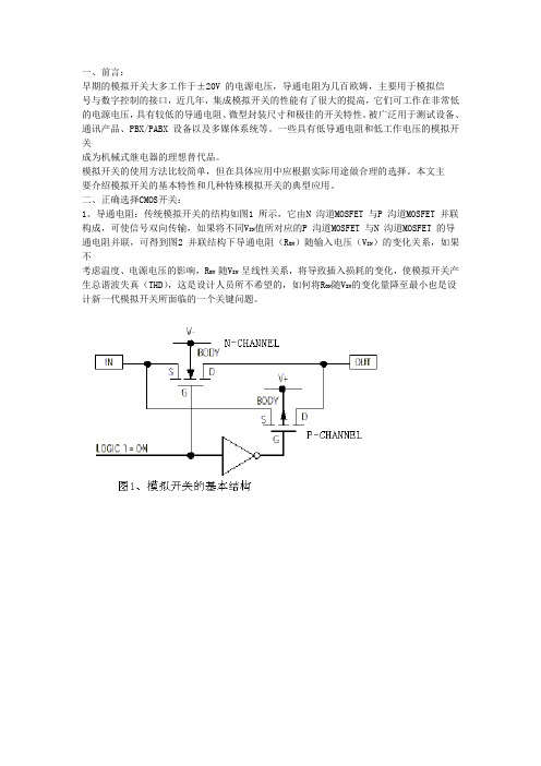
二、正确选择CMOS开关:1、导通电阻:传统模拟开关的结构如图1 所示,它由N 沟道MOSFET 与P 沟道MOSFET 并联构成,可使信号双向传输,如果将不同V IN值所对应的P 沟道MOSFET 与N 沟道MOSFET 的导通电阻并联,可得到图2 并联结构下导通电阻(R ON)随输入电压(V IN)的变化关系,如果不考虑温度、电源电压的影响,R ON 随V IN 呈线性关系,将导致插入损耗的变化,使模拟开关产生总谐波失真(THD),这是设计人员所不希望的,如何将R ON随V IN的变化量降至最小也是设计新一代模拟开关所面临的一个关键问题。
另外,导通电阻还与开关的供电电压有关,由图3 可以看出:R ON随着电源电压的减小而增大,当MAX4601的电源电压为5V 时,最大R ON为8Ω;当电源电压为12V 时,最大R ON为3Ω;电源电压为24V时,最大R ON仅为2.5Ω。
R ON的存在会使信号电压产生跌落,跌落量与流过开关的电流成正比,对于适当的电流这一跌落量在系统容许的误差范围内,而要降低R ON所耗费的成本却很高,因此,应根据实际需要加以权衡。
R ON 确定后,还需考虑通道间的失配度与R ON的平坦度。
ATMEL代理通道失配度用来描述同一芯片不同通道间R ON 的差别;R ON 的平坦度用于描述每一通道的R ON在所规定的信号范围内的变化量。
