3500-20本特利3500控制器说明手册
3500说明书

Revision NC, July 20023500/33 16 CHANNEL RELAY MODULEOPERATION ANDMAINTENANCE MANUALCopyright © 2002 Bently NevadaAll Rights Reserved.The information contained in this document is subject to change without notice.The following are trademarks of Bently Nevada in the United States and other countries: Actionable Information™, Actionable Information to theRight People at The Right Time™, ADRE®, BentlyNevada®, CableLoc™, Data Manager®, DecisionSupport™, DemoNet™, Dynamic Data Manager®,Dynamic Transmitor™, Engineer Assist™,FieldMonitor™, FluidLoc™, FlexiTIM™, FlexiTAM™,Helping you Protect and Manage All Your Machinery®,HydroVU™, Key ∅®, Keyphasor®, Machine ConditionManager™ 2000, MachineLibrary™, MicroPROX®,Move Data, Not People™, Move Information, NotData™, Performance Manager™, PROXPAC®,Proximitor®, REBAM®, Seismoprobe®, System 1™,TDIXconnX™, Tecknowledgy™, TipLoc™,TorXimitor®, Transient Data Manager®,Trendmaster®, TrimLoc™, VAM™, Velomitor®,Xlerometer™Bently Nevada’s orbit logo and other logos associatedwith the trademarks in bold above, are also alltrademarks or registered trademarks of Bently Nevadain the United States and other countries."The following ways of contacting Bently Nevada are provided for those times when you cannot contact your local Bently Nevada representative:Mailing Address 1631 Bently Parkway SouthMinden, NV 89423USATelephone 1 775 782 36111 800 227 5514Fax 1 775 782 9259Internet 3500/33 Operation and MaintenanceAdditional InformationNOTICE:This manual does not contain all the information required to operate andmaintain the 16 Channel Relay Module. Refer to the following manualsfor other required information.3500 Monitoring System Rack Installation and Maintenance Manual (129766-01)• general description of a standard system• instructions for installing and removing the module from a 3500 rack• drawings for all cables used in the 3500 Monitoring System3500 Monitoring System Rack Configuration and Utilities Guide (129777-01)• guidelines for using the 3500 Rack Configuration software for setting the operating parameters of the module• guidelines for using the 3500 test utilities to verify that the input and output terminals on the module are operating properly3500 Monitoring System Computer Hardware and Software Manual (128158-01)• instructions for connecting the rack to 3500 host computer• procedures for verifying communication• procedures for installing software• guidelines for using Data Acquisition / DDE Server and Operator Display Software• procedures and diagrams for setting up network and remote communications3500 Field Wiring Diagram Package (130432-01)• diagrams that show how to hook up a particular transducer• lists of recommended wiringiii3500/33 Operation and Maintenanceiv Contents1Receiving and Handling Instructions (1)1.1Receiving Inspection (1)1.2Handling and Storing Considerations (1)1.3Disposal Statement (1)2General Information (3)2.1The 16 Channel Relay Module (4)2.2Statuses (8)2.3LED Descriptions (10)2.3.116 Channel Relay Module (10)3Configuration Information (11)3.1Hardware Considerations (11)3.2Entering Alarm Drive Logic (11)3.2.1Relay Module Configuration Considerations (12)3.2.2Relay Module Configuration Options (13)3.3Software Switches (16)4Output Module Description (19)4.116 Channel Relay Output Module (19)4.2Wiring Euro Style Connectors (22)5Maintenance (25)5.1Verifying a 3500 Rack - Relay Module (25)5.1.1Choosing a Maintenance Interval (25)5.1.2Required Test Equipment (26)5.1.3Typical Verification test setup (26)5.1.4Using the Rack Configuration Software (28)5.1.5Standard Relay Channels (29)5.1.6If a Channel Fails a Verification Test (30)5.2Performing Firmware Upgrades (31)5.2.116 Channel Relay Firmware Upgrade Procedure (31)6Troubleshooting (33)6.1Self-test (33)6.2LED Fault Conditions (34)6.3System Event List Messages (35)6.4Alarm Event List Messages (44)7Ordering Information (45)7.116 Channel Relay Module (45)8Specifications (47)8.13500/33 16 Channel Relay Module (47)3500/33 Operation and Maintenance 1 Receiving and Handling Instructions 1 Receiving and Handling Instructions1.1 Receiving InspectionVisually inspect the module for obvious shipping damage. If shipping damage isapparent, file a claim with the carrier and submit a copy to Bently Nevada.1.2 Handling and Storing ConsiderationsCircuit boards contain devices that are susceptible to damage when exposed toelectrostatic charges. Damage caused by obvious mishandling of the board willvoid the warranty. To avoid damage, observe the following precautions in theorder given.Application AlertMachinery protectionwill be lost when thismodule is removedfrom the rack.• Do not discharge static electricity onto the circuit board. Avoid tools or procedures that would subject the circuit board to static damage. Somepossible causes include ungrounded soldering irons, nonconductive plastics,and similar materials.• Personnel must be grounded with a suitable grounding strap (such as 3M Velostat No. 2060) before handling or maintaining a printed circuit board.• Transport and store circuit boards in electrically conductive bags or foil.• Use extra caution during dry weather. Relative humidity less than 30% tends to multiply the accumulation of static charges on any surface.• When performed properly, this module may be installed into or removed from the rack while power is applied to the rack. Refer to the Rack Installation andMaintenance Manual (part number 129766-01) for the proper procedure. 1.3 Disposal StatementCustomers and third parties that are in control of product at the end of its life orat the end of its use are solely responsible for proper disposal of product. Noperson, firm, corporation, association or agency that is in control of product shalldispose of it in a manner that is in violation of United States state laws, UnitedStates federal laws, or any applicable international law. Bently Nevada is notresponsible for disposal of product at the end of its life or at the end of its use.13500/33 Operation and Maintenance 23500/33 Operation and Maintenance 2 General Information 2 General InformationThe 16 Channel Relay Module can be used for most monitoring applications. Ituses a single relay to drive the output for each channel. See section 2.1 foradditional information on the 16 Channel Relay Module.1) LEDs indicating the module status.2) LEDs indicating the status of the Relay Channels.3) Terminals for connecting relay contacts to external devices.4) Switches that control how the relay contacts work.32 General Information 3500/33 Operation and Maintenance 2.1 The 16 Channel Relay ModuleThe 16 Channel Relay Module is a full-height module that provides 16 relayoutputs. Any number of 16 Channel Relay Modules can be placed in any of theslots to the right of the Rack Interface Module.Each relay output is fully programmable using AND and OR voting. The AlarmDrive Logic for each relay channel can use alarming inputs (alerts, dangers, Not-OK, and individual channel parameters) from any monitor channel in the rack.This Alarm Drive Logic is programmed using the Rack Configuration Software.The three common types of Alarm Drive Logic configurations are bussed relays,individual relays, and independent relays. Bussed relays use an Alarm DriveLogic that ORs the Alerts or Dangers for all channels in the rack to drive a singlerelay. Individual relays use Alarm Drive Logic that ORs the Alerts or Dangers forchannel pairs (channel 1 and channel 2 or channel 3 and channel 4) in a monitorto drive a single relay. Independent relays use Alarm Drive Logic that causeeach alarm level (Alert and Danger) from a channel to drive a separate relaychannel. The following examples show the drive logic for these three types oflogic.S = Monitor Slot A1 = Alert/Alarm 1C = Channel A2 = Danger/Alarm 243500/33 Operation and Maintenance 2 General Information Bussed Relays (Alert and Danger)##A1 = Any Active Alert ##A2 = Any Active Danger((S02C##A1) OR (S03C##A1) OR ... OR (S15C##A1)) è Trip Relay Channel 1((S02C##A2) OR (S03C##A2) OR … OR (S15C##A2)) è Trip Relay Channel 2Bussed Relays52 General Information 3500/33 Operation and Maintenance6 Individual Relays (Alert and Danger)(S02C01A1) OR (S02C02A1) è Trip Relay Channel 1 (Alert Relay) (S02C01A2) OR (S02C02A2) è Trip Relay Channel 2 (Danger Relay) (S02C03A1) OR (S02C04A1) è Trip Relay Channel 3 (Alert Relay) (S02C03A2) OR (S02C04A2) è Trip Relay Channel 4 (Danger Relay)Individual RelaysIndependent Relays (Alert and Danger)(S02C01A1) è Trip Relay Module in slot 3 Channel 1(S02C02A1) è Trip Relay Module in slot 3 Channel 2(S02C03A1) è Trip Relay Module in slot 3 Channel 3(S02C04A1) è Trip Relay Module in slot 3 Channel 4(S02C01A2) è Trip Relay Module in slot 16 Channel 1(S02C02A2) è Trip Relay Module in slot 16 Channel 2(S02C03A2) è Trip Relay Module in slot 16 Channel 3(S02C04A2) è Trip Relay Module in slot 16 Channel 4Independent relays require that you install two 16 Channel Relay Modules for each monitor module.Independent Relays2.2 StatusesThe 16 Channel Relay Module will return both module and channel statuses.This section describes the available statuses and where they can be found.Module StatusOKThis indicates if the 16 Channel Relay Module is functioning correctly. A notOK status is returned under any of the following conditions:• Hardware Failure in the module• Node Voltage Failure• Configuration Failure• Slot ID FailureIf the Module OK status goes not OK, then the system OK Relay on the RackInterface I/O Module will be driven not OK.Configuration FaultThis indicates if the 16 Channel Relay Module configuration is invalid.BypassThis indicates if any of the channels in the 16 Channel Relay Module hasbeen bypassed. Any of the following conditions can cause the Relay Moduleto be bypassed:• A channel has never been configured• The Relay Module is in configuration mode• A Fatal error was found during self-test• Rack Alarm Inhibit has occurred• A channel has an invalid configuration• Any active channel is bypassedAlarm 1 ActiveThis indicates that one or more of the channels of the 16 Channel RelayModule is in alarm.Channel StatusOKThis indicates that no fault has been detected by the associated 16 ChannelRelay Module channel. If the Channel OK status goes not OK, then thesystem OK Relay on the Rack Interface I/O Module will be driven not OK.BypassThis indicates if the associated 16 Channel Relay Module channel has been bypassed. Any of the following conditions can cause the channel to bebypassed:• The channel has never been configured• The Relay Module is in configuration mode• A Fatal error was found during self-test• Rack Alarm Inhibit has occurred• The channel has an invalid configuration• The channel is bypassed using a software switchChannel OffThis indicates if the associated 16 Channel Relay Module channel has been turned off (not Active). The Relay channels may be turned off (inactivated) using the Rack Configuration Software.Alarm 1 ActiveThis indicates if the associated 16 Channel Relay Module channel is inalarm.The following table shows where the statuses can be found.Statuses Comm.GatewayModuleRackConfigurationSoftwareOperatorDisplaySoftware3500/94VGADisplayModule OK X X X Module ConfigurationFaultXModule Bypass XModule Alert/Alarm 1ActiveX X X Channel OK X X X X Channel Bypass X X X X Channel Off X X X Channel Alert/Alarm 1ActiveX X X2.3 LED DescriptionsThe LEDs on the front panel of the 16 Channel Relay Module indicate theoperating status of the module as shown in the following figures. Refer toSection 6.2 for all of the available LED conditions.2.3.1 16 Channel Relay Module1) OKIndicates that the 16 Channel Relay Module andthe 16 Channel Relay Output Module areoperating correctly.2) TX/RXFlashes at the rate that messages are received.3) Channel AlarmIndicates that an alarm condition has occurredwith this relay.3 Configuration InformationConfigure 3500 relay modules by using the Relay Association screen to enteralarm drive logic for each relay channel and by using the Software Switchesscreen to set software switches. This section defines the options on theseconfiguration screens. The Rack Configuration and Utilities Guide (part number129777-01) shows how to operate those screens.3.1 Hardware ConsiderationsThe Slots in the rack are numbered from 0 to 15, counting from left to right. Thepower supplies go into slot 0 and the Rack Interface module goes into slot 1.Slots 2 through 15 are called “monitoring positions”. The 3500/33 module canbe installed into any of the monitoring positions. However, if the 3500/20 RackInterface Module and Data Manager I/O are to be used to interface to DDIX,TDIX or TDXnet, refer to the manual on the 3500/20 for slot restrictions this mayplace on your configuration.3.2 Entering Alarm Drive LogicUse the Relay Association screen to enter the alarm logic that controls whatalarms cause the channels in the relay to drive the output.Relay Association Screen for a 16 Channel Relay Module3.2.1 Relay Module Configuration Considerations•Add monitor modules to the rack configuration before configuring the Relay Module.• Activate only the Relay Module channels that will be used.• Only monitor modules may be used in the alarm drive logic.• Plan ahead to determine if any channels will be configured as channel pairs (DPDT).• Consider if your application will need True or Normal AND voting logic.• When configuring several channels with similar logic or conditions, consider utilizing the Copy function.• Prior to downloading, the configuration software will determine if the number of instructions exceeds the limit of your relay module. The 16-Channel Relaymodule is limited to 100 logical operations per channel for each of the 16channels.• Prior to exiting the Relay Association screen, the configuration software will determine if there are errors in any channel alarm drive logic. The cursor willbe placed at the location of the syntax error.3.2.2 Relay Module Configuration OptionsAvailable MonitorsA field that shows the monitors in the rack.Rack TypeThe type of Rack Interface Module installed in the rack (Standard or TMR).Config IDA unique six character identifier which is entered when a configuration isdownloaded to the 3500 rack.Relay SlotThe location in the 3500 rack of the relay module being configured.ActiveA check box that applies to the selected channel in the Channel Associationgroup. The relay channel drives the output only when this box is enabled (x)and the alarm drive logic for the channel is true.Latching RelaysWhen this option is selected, the corresponding relay alarm channel will hold thealarm state until it receives a rack reset or the relay is reconfigured.Relay Channel Pair (DPDT)When this option is selected, the current channel will be grouped with its channelpair, thus allowing both channels to have identical configurations and alarmlogic.Standard Relay Channel AssociationA group for selecting the channel, or channel pair, to be configured andactivated.Relay NE/NDE Switch StatusIndicates how the relay hardware switches are set on the Relay Output Module.This status is only available after the relay has been uploaded.Available Monitor Channels/AlarmsWhen a monitor is selected, this area shows all the alarms that are available forthe relay module.Alarm Drive LogicBuild the alarm drive logic in this area using the available monitor alarms. AND Voting SetupThis option allows you to determine the type of AND voting for a standard rack type.AND Voting Setup ScreenNormal AND Voting (Default)With this option selected, if an alarming parameter is Not OK or bypassed (either by user selection or monitor failure), then the parameter will be removed from the relay logic. Please note: A “Not-OK” alarming parameter (a parameter intended to alarm on a Not-OK condition) will not be removed from the alarm logic equation.True AND VotingSelecting True AND logic causes alarming parameters that are Not OK or bypassed to remain in the relay logic. Using 'True And' logic will not drive an alarm if an alarming parameter being And-ed is Not OK (parameters not intended to alarm on a Not-OK condition) or in bypass.Important: Care must be taken when selecting the AND voting to be used; consider the configuration settings for the channel to be used as an alarm parameter. Not OK Channel Defeat (single channel measurements), Not OK Channel Pair Defeat (paired channel measurements), Timed OK Channel Defeat and Latching vs. Non-Latching Not OK modes all affect the circumstances that cause a channel to be "Not OK" or bypassed. The following channel types have special scenarios to consider:Thrust Position: Monitor reports an Alarm (not a "Not OK" condition) to the relay module for a transducer not OK.Overspeed, Zero-Speed, Rotor Speed: These channel types have optional "OK Voltage Checks" that will determine if the monitor will or will not report a Not OK status to the relay module due to a transducer voltage error.Eccentricity: "Direct Channel Above 600 RPM" affects bypass and Not OK status.3.3 Software SwitchesSoftware switches for relay modules let you temporarily bypass or inhibit therelay module and channel functions. Set these switches on the SoftwareSwitches screen under the Utilities Option on the main screen of the RackConfiguration Software. Switch settings take affect only after you press the Setbutton.Configuration ModeA switch that allows the 16 Channel Relay Module to be configured. Toconfigure a relay module, enable (x) this switch and set the key switch on thefront of the Rack Interface Module in the PROGRAM position. Whendownloading a configuration from the Rack Configuration Software, this switchwill automatically be enabled and disabled by the Rack Configuration Software.If the connection to the rack is lost during the configuration process, use thisswitch to remove the module from Configuration Mode.The module switch number is used in the Communication Gateway Module.Module Switch Number Switch Name1 Configuration Mode3500/33 Operation and Maintenance 3 Configuration InformationBypassWhen enabled (x), the channel will be turned off and not allow alarming.The channel switch number is used in the Communication Gateway Module.Channel Switch Number Switch Name1 Bypass3 Configuration Information 3500/33 Operation and Maintenance3500/33 Operation and Maintenance 4 I/O Modules Description 4 Output Module DescriptionThis section describes the Output module that is associated with the 16 ChannelRelay Module. This section also describes how to use the connectors on theRelay Output Module and describes where to install each Output module.4.1 16 Channel Relay Output ModuleThe 16 Channel Relay Output Module contains 16 sets of relay contacts (one foreach channel) and can be setup so each channel (in groups of four channels) isNormally Energized or Normally De-energized. The 16 Channel Relay OutputModule must be installed behind the 16 Channel Relay Module (in a Rack Mountor a Panel Mount rack) or above the 16 Channel Relay Module (in a Bulkheadrack).1) Terminals for connecting tothe single-pole, double-throw(SPDT) relays.2) DIP switches for configuringthe relays for NormallyEnergized (NE) or NormallyDe-energized (NDE). Thenumbers refer to relaychannel groups. Forexample, CH1-4 correspondsto relay channels 1 thru 4.4 I/O Modules Description 3500/33 Operation and MaintenanceConfiguring the Normally Energized and De-Energized Relays1) Screwdriver2) Module Cover3) DIP SwitchCAUTIONProper dipswitch configuration techniquerequires the Output module to be removedfrom the rack. Failure to follow this warningcould expose personnel to dangerously highvoltage levels that could cause shock or burnsand damage to the Output Module.CAUTIONProper Output module installation requirespower to be removed from the rack. Failure tofollow this warning could cause seriousdamage to the Output Module.3500/33 Operation and Maintenance 4 I/O Modules DescriptionNoteRelay contacts are marked NC (Normally Closed), NO (Normally Open), andARM (Armature). NC and NO define the state of the relay contacts with nopower applied to the relay coil (de-energized , non-alarm state).Normally Energized Normally De-energized(NE) (NDE)1) No Power/ No Alarm (shelf state)2) With Power/ No Alarm3) With Power/ In Alarm4 I/O Modules Description 3500/33 Operation and Maintenance 4.2 Wiring Euro Style ConnectorsTo remove a terminal block from its base, loosen the screws attaching theterminal block to the base, grip the block firmly and pull. Do not pull the blockout by its wires because this could loosen or damage the wires or connector.WARNINGHigh voltage may be present on the relay contacts or relay wiring.This voltage could cause shock, burns or death. Use proper isolationtechniques.Remove all power when working with the relays.3500/33 Operation and Maintenance 4 I/O Modules Description Refer to the 3500 Field Wiring Diagram Package for the recommended wiring.Do not remove more than 6 mm (0.25 in) of insulation from the wires.5 Maintenance 3500/33 Operation and Maintenance3500/33 Operation and Maintenance 5 Maintenance 5 MaintenanceThe boards and components inside of 3500 modules cannot be repaired in thefield. Maintaining a 3500 rack consists of testing module channels to verify thatthey are operating correctly. Modules that are not operating correctly should bereplaced with a spare.When performed properly, the main module may be installed into or removedfrom the rack while power is applied to the rack. The relay output module shouldonly be installed or removed when the power to the rack has been removed.Refer to the Rack Installation and Maintenance Manual (part number 129766-01)for the proper procedure.This section shows how to verify the operation of the 3500/33 16 Channel RelayModule.5.1 Verifying a 3500 Rack - Relay ModuleThe 3500 Monitoring System is a high precision instrument that requires nocalibration. The functions of Relay Module channels, however, must be verifiedat regular intervals. At each maintenance interval, we recommend that you usethe procedures in this section to verify the operation of all active channels in theRelay Module.Section Number Topic PageNumber5.1.1 Choosing a Maintenance Interval 255.1.2 Required Test Equipment 265.1.3 Typical Verification Test Setup 265.1.4 Using the Rack Configuration Software 285.1.5 Standard Relay Channels 295.1.1 Choosing a Maintenance IntervalUse the following approach to choose a maintenance interval:• Start with an interval of one year and then shorten the interval if any of the following conditions apply:o Monitored machine is classified as criticalo 3500 rack is operating in a harsh environment such as in extremetemperature, high humidity, or in a corrosive atmosphere • At each interval, use the results of the previous verifications and ISO Procedure 10012-1 1992(E) to adjust the interval.5 Maintenance 3500/33 Operation and Maintenance5.1.2 Required Test EquipmentThe test equipment needed to simulate the inputs for the relay channel willdepend on the type of monitor providing inputs to the Relay Alarm Drive Logic.This equipment can be found under Required Test Equipment in theMaintenance section of the specific monitor manual.5.1.3 Typical Verification test setupThe following figure shows the typical test setup for verifying a Relay Module.The test equipment is used to simulate the transducer signal to selectedmonitors and the laptop computer is used to observe the output from the rack.1) 3500 Rack2) Test Equipment3) RS-232 communications4) Laptop ComputerTransducers can be connected to a 3500 rack in a variety of ways. Dependingon the wiring option for the I/O module of your monitor, connect the testequipment to the Monitor Module and Relay Module using one of the followingmethods:3500/33 Operation and Maintenance 5 Maintenance1) Connect test equipment here.2) Inputs3) Monitor I/O Module (Internal Termination)4) External Termination Block (Euro Style Connectors)5) External Termination Block (Terminal Strip Connectors)5 Maintenance 3500/33 Operation and Maintenance1) Outputs16 Channel Relay Output Module5.1.4 Using the Rack Configuration SoftwareThe laptop computer that is part of the test setup uses the Rack ConfigurationSoftware to display output from the rack and to reset certain operatingparameters in the rack. To perform the test procedures in this section you mustbe familiar with the following features of the Rack Configuration Software.• upload and save configuration files• display the Verification screenThe Rack Configuration and Test Utilities Guide (part number 129777-01)explains how to perform these operations.NoteSave the original rack configuration before doing any maintenanceor troubleshooting procedures.3500/33 Operation and Maintenance 5 Maintenance The Verification screen displays relay channel output from a 3500 rack as shownin the following figure. Information such as Alarm Drive Logic, Channel AlarmState and Channel OK State are used to verify relay channels.5.1.5 Standard Relay ChannelsVerify relay channels by forcing alarms from the monitors that provide inputs forthe Relay Alarm Drive Logic. When the logic is true, the Channel Alarm Statewill change to Alarm on the Verification screen and the alarm relay and frontpanel LED for that channel will change state. Verify only those channels that areactive and configured.To verify that a 16 Channel Relay channel is working correctly.1. Run the Rack Configuration Software on the test computer.2. Choose Verification from the Utilities menu. A screen prompting for theslot and channel number of the relay to be tested will appear.3. Choose the proper Slot number and Channel number and then click on theVerify button. The Verification screen will appear.4. Verify that the Channel OK State status on the Relay Verification screenreads OK.5. Use the Relay Verification screen to determine what inputs must besimulated.6. Simulate the required Alarm Drive Logic inputs to cause the relay to changestates.。
本特利3500中文说明书

TSI系统调试基本知识本内容将围绕大多数电厂中广泛使用的美国本特利(BENTLY)公司生产的振动检测系统3500为模版,全面讲述系统安装、组态、调试过程及调试中常见问题的处理。
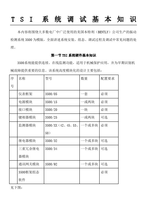
第一节 TSI系统硬件基本知识3500系统能提供连续、在线监测功能,适用于机械保护应用,并为早期识别机械故障提供重要的信息。
该系统高度模块化的设计主要包括:见下图:系统的工作流程是:从现场取得的传感器输入信号提供给3500监测器框架内的监测器和键相位通道,数据被采集后,与报警点比较并从监测器框架送到一个地方或多个地方处理。
3500框架中模件的共同特征是带电插拔和内部、外部接线端子。
任何主模件(安装在3500框架前端)能够在系统供电状态中拆除和更换而不影响不相关模块的工作,如果框架有两个电源,插拔其中一块电源不会影响3500框架的工作。
外部端子使用多芯电缆(每个模块一根线)把输入\输出模块与终端连接起来,这些终端设备使得在紧密空间内把多条线与框架连接起来变的非常容易,内部端子则用于把传感器与输入\输出模块直接连接起来。
外部端子块一般不能与内部端子输入/输出模块一起使用。
1、3500/05系统框架3500框架用于安装所有的监测器模块和框架电源。
它为3500各个框架之间的互相通讯提供背板通讯,并为每个模块提供所要求的电源。
3500框架有两种尺寸:1 全尺寸框架——19英寸EIA框架,有14个可用模块插槽2 迷你型框架——12英寸框架,有7个可用模块插槽电源和框架接口模块必须安装于最左边的两个插槽中。
其余14个框架位置(对与迷你型框架来说是其余7个位置)可以安装任何模块。
2、3500/15电源模块3500 电源是半高度模块,必须安装在框架左边特殊设计的槽口内。
3500 框架可装有一个或两个电源(交流或直流的任意组合)。
其中任何一个电源都可给整个框架供电。
如果安装两个电源,第二个电源可做为第一个电源的备份。
当安装两个电源时,上边的电源作为主电源,下边的电源作为备用电源,只要装有一个电源,拆除或安装第二个电源模块将不影响框架的运行。
本特利3500中文说明书
传感器缓冲输出:前面板对应每一通道均有同轴接头,每一同轴接头都有短路保护
20到30Vdc输入:10.0A(最大)。
输出:前面板发光二极管
电源OKLED:当电源工作正常时,灯亮。
单点接地线连接:为避免接地回路,系统必须提供一单点接地,电源输入模块为你提供了一个开关,来区别控制系统在哪儿接地。如果装了两个电源,那么两个开关需要调到同一位置。电源输入模块出厂时,开关调到关(CLOSED);接地系统通过末端(END)引到端子连接器上,如果系统在另一个地方接地,比如用外部安保器,需把开关调到(OPENED)。下图演示了如何把开关跳到(OPENED)位置。
3、3500/20框架接口模块
框架接口模块(RIM)是3500框架的基本接口。它支持本特利内华达用于框架组态并调出机组中信息的专有协议。框架接口模块必须放在框架中的第一个槽位(紧靠电源的位置)。RIM可以与兼容的本特利内华达通讯处理器,如TDXnet、TDIX和DDIX等连接。虽然RIM为整个框架提供某些通用功能,但它并不是重要监测路径中的一部分,对整个监测系统的正确和正常运行没有影响。每个框架需要一个框架接口模块。
1.交流电源
2.高压直流电源
3.低压直流电源
输入电源选项:
175到264Vacrms:(247到373Vac,pk),47到63Hz。该选项使用交流电源且为高电压(通常220V)交流电源输入模块(PIM)。安装版本R以前的交流电源输入模块(PIM)和/或版本M以前的电源模块要求电压输入:175到250Vacrms。
通讯网关模块
3500/92
一个或多块
可选
3500框架组态软件
必须
见下图:
仪表本特利3500系统

延伸电缆和探头的长度总和必须等于前置器上标明的总电气长度
4、振动、位移变送器
3500监测系统的组成
5、电涡流 电感线圈产生的磁力线经过金属导体时,金属导体就会产生感应电流,且呈闭合回路,类似于水涡流形状,故称之 为电涡流也叫做电涡流效应.
3500监测系统的组成
3500监测系统的作用
4、键相传感器 电涡流传感器可以用来有效得提供基准相位信息。键相传感器的典型安装是将其探头呈放射状安装在转子周围,当转轴每次旋转时,就可以感知轴上设计特征信息(键槽等)。键相传感器可以创建一个基准信号用于测量绝对相位信息及确定机器的转速。 前置器系统被安装好之后,将观测到大轴上的“凹槽”或“突出”的地方会比正常的振动或距离测量产生明显的电压变化。这种明显的差别使得3500监测系统将每转一周产生的有用的信号与背景的噪音信号或振动信号区分开来。键相位信号在机组故障诊断中非常有用。
3500监测系统的作用
0
+
-
从驱动器向轴的驱动端看去。是垂直或Y探头始都在水平或X探头向左或逆时针90方位上。方向一般为左45度和右45度。振动探头的基准电压一般在-8~-12V之间,一般为-9.75V,距离单位为UM PP(PP为峰峰值)。
3500监测系统的组成
2、延长导线(1)延长导线的结构:导体芯、内屏蔽层、外屏蔽层、绝缘层。 1)内屏蔽层和导体芯提供了顶部线圈到探头电缆微型连接器末端的连接。 2)外屏蔽层是没有连接到线圈或连接器,所以它不是系统的电气性能的一部分。这个外屏蔽层提供了内屏蔽层的 机械保护。如果电缆的外层聚四氟乙烯涂层损坏,这可以防止不必要的线圈接地。内屏蔽接前置器COM端,如 果在正常生产中外屏蔽遭到破坏建议及时更换。不同型号、类型接头塑封的颜色不同,如蓝色、紫色、灰色。(2) 延长导线标签含义例如:330130-080-00-00 080 = 8.0米的总长度 00 =没有防护型外壳 00 =危险区域,不需认证 3300 XL电涡流传感器系统, 可用扩展电缆长度为3.0,3.5, 4.0,4.5,7.5,8.0和8.5米。
本特利3500模块软件操作方法

本特利3500软件操作方法本特利3500系统是TSI系统,也就是汽轮机安全监测系统,主要是用来监测汽轮机的振动、位移、转速、压力、键相、胀差等主要参数的。
本特利3500系统由硬件和组态软件组成。
一、硬件组成1、3500机架,模块2、3500探头,前置器3、双电源模块,一块常用,一块备用4、通讯模块,用于给系统组态5、其他监测模块,根据需要选取二、软件组成1、3500组态软件2、设置通讯模块IP地址右键点击通讯模块,在右键菜单选择“选项”按钮,在红色方框中设置设备名称,PI地址,子网掩码,和网关。
3、其他模块组态右键单击空白模块,选择“Monitors”,在扩展菜单中选择与硬件模块对应的型号。
振动和位移用的模块,探头和前置器都是一样的,这里选择“42M”。
右击刚才配置的模块,选择“Options”,弹出通道设置对话框,42M模块共有4个监测通道,要对这4个通道进行设置。
设置通道类型,测量振动选择“Radial Vibration”,测量位移选择“Thrust Position”。
转速关联设置为无转速激活4个通道,点击选项按钮传感器类型选择“3300XL-8mm Proximitor”,隔离栅选择无,角度根据安装位置选择,45度安装就要勾选“Left”或“Right”。
点“OK”点击“Customize”进入自定义选项,将英制单位改成公制单位,点“OK”点击变量和报警标签,量程选择“0-500um pp”,或者自定义量程,取消勾选报警联锁“Alert Latching”和危险联锁“Danger Latching”,延时“Delay”都选1秒。
点“OK”完成以上设置后,返回到组态画面,右击模块选择“Setpoins”,设置报警值,危险值,报警设置80um,并勾选启用“Enabled”,危险值设置100um,并勾选“Enabled”,4个通道方法一样,以此类推。
设置完后点“OK”,返回组态画面。
再右击模块,选择“Point Names”取名字,可以取也可以不取。
Bently Nevada 3500软件商品说明书

Specifications and Ordering InformationPart Number 141527-01Rev. E (11/15)3500 SoftwareBently Nevada* Asset Condition MonitoringDescriptionRack Configuration Software is used to configure all modules of the 3500 Machinery Protection System. All 3500 software is Windows ® based and can operate across a network.Note: The primary role of the 3500 Data Acquisition and Operator Display software is as anemulation package to display the data normally found on the front-panel display of a machinery protection system. The software also provides basic trending and event archiving functions. It does not provide the dynamic data capture and plot capabilities required for machinery diagnostics or for connection to a Bently Nevada Decision Support* system.SpecificationsMinimum Computer Requirements:Rack Configuration Computer:Intel® Pentium ® processor or better 800x600 (SVGA ) or higher resolution Monitor CD-ROM drive128 Megabytes of RAM recommendedMicrosoft Windows 7 or Windows 2012 Server operating system or greaterEnglish Operating Systems onlyMinimum 35 Megabytes of available hard disk space RS232 Serial Port , USB port with USB to Serial Adapter, Modem, or Network access to 3500 racksOrdering InformationRack Configuration Software and Configuration Manual 3500/01-013500 Rack Configuration Software Support plans3500/18-A-XXA: Support type and duration0 11-year Single SoftwareSupport plan0 21-year Multi-Software Supportplan0 32-year Single SoftwareSupport plan0 42-year Multi-Software Supportplan0 53-year Single SoftwareSupport plan0 63-year Multi-Software Supportplan0 74-year Single SoftwareSupport plan0 84-year Multi-Software Supportplan0 95-year Single SoftwareSupport plan1 05-year Multi-Software SupportplanEx. 1-year Multi-Software Supportplan for 3500 Rack Config:3500/18-02 Recommended Accessories100M283310 foot A to B USB cable Backward Compatible Accessories130119-01Host Computer to RS232/RS422Converter Cable RS232129386-01TDIX - Static Data Cable 02290160DDIX/TDIX – Dynamic Data Cable 02230411RS232 to RS422 Converter 110VAC 02230412RS232 to RS422 Converter 220VAC167344USB Serial Parallel AdapterHost Computer to 3500 Rack Cable, RS232130118 -AXXXX-BXXA: Cable Length0 0 1 010 feet (3 metres)0 0 2 525 feet (7.5 metres)0 0 5 050 feet (15 metres)0 1 0 0100 feet (30.5 metres) B: Assembly Instructions0 1Not Assembled0 2AssembledRS232/RS422 Converter to 3500 Rack Cable, RS422, PVC Insulated130120 -AXXXX-BXXA: Cable Length0 0 1 0 10 feet (3 metres)0 0 2 5 25 feet (7.5 metres)0 0 5 0 50 feet (15 metres)0 1 0 0 100 feet (30.5 metres)0 2 5 0 250 feet (76 metres)0 5 0 0500 feet (152 metres)B:Assembly Instructions0 1 Not Assembled0 2AssembledHost Computer to 3500 Rack Cable, RS422, PVC Insulated132632 -AXXXX-BXXA: Cable Length0 0 1 0 10 feet (3 metres)0 0 2 5 25 feet (7.5 metres)0 0 5 0 50 feet (15 metres)0 1 0 0 100 feet (30.5 metres)0 2 5 0 250 feet (76 metres)0 5 0 0500 feet (152 metres)B: Assembly Instructions0 1Not Assembled0 2AssembledHost Computer to 3500 Rack Cable, RS422, Teflon® Insulated132633 -AXXXX-BXXA: Cable Length0 0 1 0 10 feet (3 metres)Specifications and Ordering Information0 0 2 5 25 feet (7.5 metres)00 5050 feet (15 metres)0 1 0 0 100 feet (30.5 metres)0 2 5 0 250 feet (76 metres)0 5 0 0500 feet (152 metres) B: Assembly Instructions0 1Not Assembled0 2Assembled3500 Rack to 3500 Rack Cable, RS422, PVC Insulated 130122 -AXXXX-BXXA: Cable Length0 0 1 0 10 feet (3 metres)0 0 2 5 25 feet (7.5 metres)0 0 5 0 50 feet (15 metres)0 1 0 0 100 feet (30.5 metres)0 2 5 0 250 feet (76 metres)0 5 0 0500 feet (152 metres) B: Assembly Instructions0 1 Not Assembled0 2 Assembled3500 Rack to 3500 Rack Cable, RS422, Teflon® Insulated131107 -AXXXX-BXXA: Cable Length0 0 1 0 10 feet (3 metres)0 0 2 5 25 feet (7.5 metres)0 0 5 0 50 feet (15 metres)0 1 0 0 100 feet (30.5 metres)0 2 5 0 250 feet (76 metres)0 5 0 0 500 feet (152 metres)B: Assembly Instructions0 1 Not Assembled0 2 Assembled500 Feet (152 metres) Extension Cable, RS422 (Usedwith Cables 130120, 131106, 130122, and 131107 forlengths greater than 500 feet (152 metres)).130121 -AXXXX-BXXA: Assembly Instructions0 1Not Assembled0 2AssembledB:Insulation0 1 PVC Insulated0 2Teflon® Insulate.Teflon® is a trademark of DuPontIntel® and Pentium® are trademarks of Intel CorporationMicrosoft® and Windows® are trademarks of Microsoft Corporation.©1999 - 2015 Bently Nevada, Inc. All rights reserved.* Denotes a trademark of Bently Nevada, Inc., a wholly owned subsidiary of General Electric Company.The information contained in this document is subject to change without prior notice.Printed in USA. Uncontrolled when transmitted electronically.1631 Bently Parkway South, Minden, Nevada USA 89423Phone: 1-775.782.3611 Fax: 1-775.215.2873Specifications and Ordering Information。
Bently3500 中文手册

1范围本规程主要适用于3500系统硬件、软件。
硬件系统包括:3500系统构成、各种卡件、系统电源组成等。
软件系统包括组态软件。
2.检修的一般规定2.1.1 检修项目、间隔及停用期间的规定2.1.1.1 每6个月用防静电的真空吸尘器清除以下部件的灰尘:卡件、卡件安装单元、风扇组件、电源装置2.1.1.2 每6个月清理并紧固所有电源线和接地线2.1.1.3停用期间,应作电源故障切换试验,以及电源电缆绝缘测试3.检修前的准备2.2.1 一块万用表、一套电工组合工具、一把尖嘴钳、组合扳手、信号发生器、摇表2.2.2 防静电真空吸尘器、防静电工具2.2.3 检修电子电路应遵守的原则注:当安装、调试卡件时,要使用现场防静电工具(手环、接地导线装置、鳄鱼夹和防静电扩散工作面),这些工具把技术人员和静电扩散工作表面连到同一个接地点,以防静电损坏卡件。
2.2.3.1 使用静电袋。
在把装入系统前不要把它从特殊的防静电袋中取出。
卡件取出后,袋子待以后使用。
2.2.3.2 打开前把防静电袋接地。
在打开含有半导体设备的防静电袋以前,请将其与设备外壳接触一下,或者接地。
2.2.3.3 不要触摸电路。
处理卡件时,拿卡件的两侧,不要触摸电路。
2.2.3.4 防止半导体器件局部连接。
在使用前,一定要检查和卡件相连的所有设备是否完好接地。
2.2.3.5 测试设备接地。
2.2.3.6 使用现场抗静电吸尘设备。
2.2.3.7 使用接地手环。
连接接地环到电源引入盘上的接地插座,电源引入盘的接地插座和大地相连。
2.2.3.8 不要用铅笔或圆珠笔设置小开关,防止开关触电损坏,触电损坏可能导致不必要的电路板误动作。
4.系统概述我厂的汽轮机保护装置采用的是美国本特利(BENTLY)公司生产的3500保护系统,该系统是计算机化的振动信息系统,可对旋转机械和往复式运动机械的机械状态提供所需要的信息,如不平衡、不对中,轴裂纹和轴承故障等机械问题的早期判定提供可靠依据。
本特利3500中文说明书解析
TSI系统调试基本知识本内容将围绕大多数电厂中广泛使用的美国本特利(BENTLY)公司生产的振动检测系统3500为模版,全面讲述系统安装、组态、调试过程及调试中常见问题的处理。
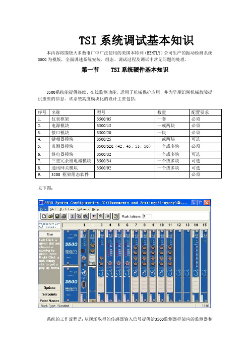
第一节 TSI系统硬件基本知识3500系统能提供连续、在线监测功能,适用于机械保护应用,并为早期识别机械故障提供重要的信息。
该系统高度模块化的设计主要包括:见下图:系统的工作流程是:从现场取得的传感器输入信号提供给3500监测器框架内的监测器和键相位通道,数据被采集后,与报警点比较并从监测器框架送到一个地方或多个地方处理。
3500框架中模件的共同特征是带电插拔和内部、外部接线端子。
任何主模件(安装在3500框架前端)能够在系统供电状态中拆除和更换而不影响不相关模块的工作,如果框架有两个电源,插拔其中一块电源不会影响3500框架的工作。
外部端子使用多芯电缆(每个模块一根线)把输入\输出模块与终端连接起来,这些终端设备使得在紧密空间内把多条线与框架连接起来变的非常容易,内部端子则用于把传感器与输入\输出模块直接连接起来。
外部端子块一般不能与内部端子输入/输出模块一起使用。
1、3500/05系统框架3500框架用于安装所有的监测器模块和框架电源。
它为3500各个框架之间的互相通讯提供背板通讯,并为每个模块提供所要求的电源。
3500框架有两种尺寸:1 全尺寸框架——19英寸EIA框架,有14个可用模块插槽2 迷你型框架——12英寸框架,有7个可用模块插槽电源和框架接口模块必须安装于最左边的两个插槽中。
其余14个框架位置(对与迷你型框架来说是其余7个位置)可以安装任何模块。
2、3500/15电源模块3500 电源是半高度模块,必须安装在框架左边特殊设计的槽口内。
3500 框架可装有一个或两个电源(交流或直流的任意组合)。
其中任何一个电源都可给整个框架供电。
如果安装两个电源,第二个电源可做为第一个电源的备份。
当安装两个电源时,上边的电源作为主电源,下边的电源作为备用电源,只要装有一个电源,拆除或安装第二个电源模块将不影响框架的运行。
本特利3500组态中文说明书
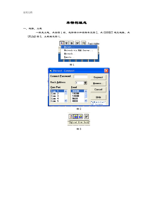
本特利组态一、连接、上载一般先上电,点击图1后,选择端口和波特率见图2,点CONNECT建立连接。
点UPLOAD图3,上载组态图4。
图1图2图3图4二、模块设置1、模拟量模块设置点击图4中左侧的options按钮,然后可以对各个模块进行组态。
以上图为例,1~7槽分别为CPU模块,增速箱振动,风机振动,风机位移,报警继电器,停车继电器,modbus通信模块。
点击图4中的2号槽进入图5的界面进行振动组态图5如图5中,选择通道信号类型,每两个通道为一组同类型信号,Radial Vibration为振动,如果信号为位移则选择Thrust Position.不测建相,将No Keyphasor打钩。
用到那个通道将该通道Active打钩。
设定量程,选择探头类型点击要设定的通道的Options按钮。
现在以图5中通道1为例,进入图6选择探头类型图6再点击图6中的进入图7选择要设定的参数量程,并且可以设置报警和停机的延迟时间。
设置好点ok保存,如果该模块四个通道信号类型,探头型号以及量程都相同,可以点击图5中的1和2按钮依次将设置好的1通道属性复制到Channel 2、Channel 3、Channel 4中。
位移的设置类似。
图72、继电器模块设置点击图4中的槽5进入图8的界面图8图8的逻辑是该继电器模块的第一路通道是第一个模拟量模块前两个通道报警信号有任何一个出现,该继电器输出。
依次可以根据实际情况设置其他通道输出逻辑。
三、报警、停机值设定点击主菜单中的如下图图9要设置振动或位移的报警、停机值,可在图9的界面中点击相应的模块图10图11振动的设置如图10,位移的设置如图11.其中可根据实际要求设置报警、停机值的上下限,需要设置的项目打钩。
如果相同类型的信号报警上下限一样,可以点击其中的进入图12界面复制到需要的通道。
图12四、3500/92的组态点击92进入通讯模块组态画面图13(组态波特率等参数),电击Configue按钮进入Congigurable Registers窗口图14,将具体振动或位移的通道DRIECT拖到右面的窗口。
本特利-3500
3500/45M(续)
继电器模块:3500/32
4/16通道继电器模块是一个全高模块,可提供4或 16个继电器的输出量。此模块的每个输出都可以独
立编程,以执行所需要的逻辑表决。
每个应用在此继电器模块上的继电器,都具有
“报警驱动逻辑”。该报警驱动逻辑可用“与门” 和“或门”逻辑编程,并可利用框架中的任何监测 器通道或任何监测器通道的组合所提供的报警输入。
径向振动
轴向位移 差胀 偏心
3500/42M(续)
①指示灯描述: OK:指示检测器I/O模块运行正常; TX/RX:接收和发送信号的速率闪动OK; BYPASS(旁路):指示该监测器的某些功 能被暂时抑制 ②传感器缓冲输出 ③位移/速度加速度带内部端子的I/O模块
3500/42M(续)---- 报警点设置
支持以下三种供电方式: 1、交流电源(175~264Vac或85~132Vac) 2、高压直流电源(88~140Vdc) 3、低压直流电源(20~30Vdc)
3500/22M框架接口模块 --------瞬态数据接口模块
3500瞬态数据接口(TDI)是3500监测系统和System机
械管理软件之间的接口。
本特利----3500
系统概述:
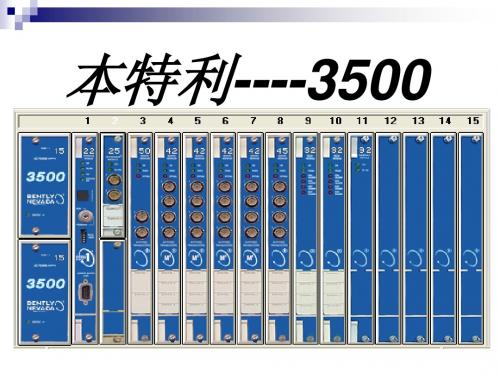
系统提供连续、在线监测功能,适用于机械保护应用。 此系统能够通过多种传感器采集数据,此硬件平台是专门为 帮助管理关键设备而设计和制造的,可为各类工厂人员提供 机械信息。
鉴于本厂动力站,此系统主要用于监测汽轮机的轴瓦 振动、轴位移、胀差及膨胀,并对位移、胀差及轴振进行报 警设置进而做出相关跳车逻辑输出。
继电器模块:3500/32
①发光二级管,指示继电器通道 工作的情况
②用来把继电器触点联到外部设 备的终端
本特利中文手册最新版3500-20
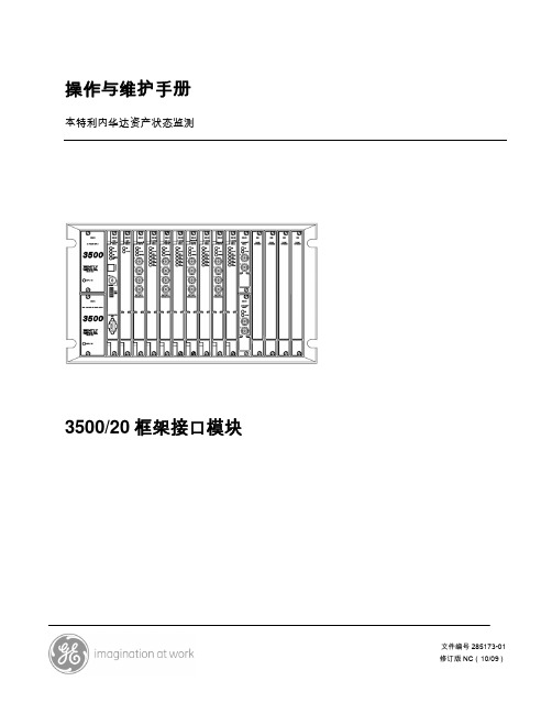
本特利内华达资产状态监测
3500/20 框架接口模块
文件编号 285173-01 修订版 NC(10/09)
3500/20 框架接口模块操作与维护手册
版权所有 2009 本特利内华达
保留所有权力
本手册内容如有更改,恕不另行通知。
以下为引用的其他法人实体的商标。
Telfon®是杜邦的注册商标。 Velostat®是3M公司的商标。
6 故障查找................................................................................................................ 52 6.1 校验................................................................................................................ 52 6.2 发光二极管LED故障状态................................................................................ 52 6.3 系统事件列表消息 .......................................................................................... 53 6.4 报警事件列表消息 .......................................................................................... 71
3.2 开关................................................................................................................ 19 3.2.1 软件开关 ................................................................................................. 19 3.2.2 硬件开关 ................................................................................................. 21
本特利3500中文说明书(完整资料).doc

此文档下载后即可编辑TSI系统调试基本知识本内容将围绕大多数电厂中广泛使用的美国本特利(BENTLY)公司生产的振动检测系统3500为模版,全面讲述系统安装、组态、调试过程及调试中常见问题的处理。
第一节TSI系统硬件基本知识3500系统能提供连续、在线监测功能,适用于机械保护应用,并为早期识别机械故障提供重要的信息。
该系统高度模块化的设计主要包括:见下图:系统的工作流程是:从现场取得的传感器输入信号提供给3500监测器框架内的监测器和键相位通道,数据被采集后,与报警点比较并从监测器框架送到一个地方或多个地方处理。
3500框架中模件的共同特征是带电插拔和内部、外部接线端子。
任何主模件(安装在3500框架前端)能够在系统供电状态中拆除和更换而不影响不相关模块的工作,如果框架有两个电源,插拔其中一块电源不会影响3500框架的工作。
外部端子使用多芯电缆(每个模块一根线)把输入\输出模块与终端连接起来,这些终端设备使得在紧密空间内把多条线与框架连接起来变的非常容易,内部端子则用于把传感器与输入\输出模块直接连接起来。
外部端子块一般不能与内部端子输入/输出模块一起使用。
1、3500/05系统框架3500框架用于安装所有的监测器模块和框架电源。
它为3500各个框架之间的互相通讯提供背板通讯,并为每个模块提供所要求的电源。
3500框架有两种尺寸:1 全尺寸框架——19英寸EIA框架,有14个可用模块插槽2 迷你型框架——12英寸框架,有7个可用模块插槽电源和框架接口模块必须安装于最左边的两个插槽中。
其余14个框架位置(对与迷你型框架来说是其余7个位置)可以安装任何模块。
2、3500/15电源模块3500 电源是半高度模块,必须安装在框架左边特殊设计的槽口内。
3500 框架可装有一个或两个电源(交流或直流的任意组合)。
其中任何一个电源都可给整个框架供电。
如果安装两个电源,第二个电源可做为第一个电源的备份。
当安装两个电源时,上边的电源作为主电源,下边的电源作为备用电源,只要装有一个电源,拆除或安装第二个电源模块将不影响框架的运行。
本特利3500中文说明书

本特利3500中文说明书TSI系统调试基本知识本内容将围绕大多数电厂中广泛使用的美国本特利(BENTLY)公司生产的振动检测系统3500为模版,全面讲述系统安装、组态、调试过程及调试中常见问题的处理。
第一节 TSI系统硬件基本知识3500系统能提供连续、在线监测功能,适用于机械保护应用,并为早期识别机械故障提供重要的信息。
该系统高度模块化的设计主要包括:序号名称型号数量配置要求1.仪表框架3500/05 一套必须2.电源模块3500/15 一或两块必须3.接口模块3500/20 一块必须4.键相器模块3500/25 一或两块可选5.监测器模块3500/XX(42、45、53、50)一个或多块必须6.继电器模块3500/32 一个或多块可选7.三重冗余继电器模块3500/34 一个或多块可选8.通讯网关模块3500/92 一个或多块可选9.3500 框架组态软件必须见下图:系统的工作流程是:从现场取得的传感器输入信号提供给3500监测器框架内的监测器和键相位通道,数据被采集后,与报警点比较并从监测器框架送到一个地方或多个地方处理。
3500框架中模件的共同特征是带电插拔和内部、外部接线端子。
任何主模件(安装在3500框架前端)能够在系统供电状态中拆除和更换而不影响不相关模块的工作,如果框架有两个电源,插拔其中一块电源不会影响3500框架的工作。
外部端子使用多芯电缆(每个模块一根线)把输入\输出模块与终端连接起来,这些终端设备使得在紧密空间内把多条线与框架连接起来变的非常容易,内部端子则用于把传感器与输入\输出模块直接连接起来。
外部端子块一般不能与内部端子输入/输出模块一起使用。
1、3500/05系统框架3500框架用于安装所有的监测器模块和框架电源。
它为3500各个框架之间的互相通讯提供背板通讯,并为每个模块提供所要求的电源。
3500框架有两种尺寸:1 全尺寸框架——19英寸EIA框架,有14个可用模块插槽2 迷你型框架——12英寸框架,有7个可用模块插槽电源和框架接口模块必须安装于最左边的两个插槽中。
安鼻适中文说明书

安鼻适中文说明书篇一:本特利3500中文说明书TSI系统调试基本知识本内容将围绕大多数电厂中广泛使用的美国本特利(BENTLY)公司生产的振动检测系统3500为模版,全面讲述系统安装、组态、调试过程及调试中常见问题的处理。
第一节 TSI系统硬件基本知识3500系统能提供连续、在线监测功能,适用于机械保护应用,并为早期识别机械故障提供重要的信息。
该系统高度模块化的设计主要包括:见下图:系统的工作流程是:从现场取得的传感器输入信号提供给3500监测器框架内的监测器和键相位通道,数据被采集后,与报警点比较并从监测器框架送到一个地方或多个地方处理。
3500框架中模件的共同特征是带电插拔和内部、外部接线端子。
任何主模件(安装在3500框架前端)能够在系统供电状态中拆除和更换而不影响不相关模块的工作,如果框架有两个电源,插拔其中一块电源不会影响3500框架的工作。
外部端子使用多芯电缆(每个模块一根线)把输入\输出模块与终端连接起来,这些终端设备使得在紧密空间内把多条线与框架连接起来变的非常容易,内部端子则用于把传感器与输入\输出模块直接连接起来。
外部端子块一般不能与内部端子输入/输出模块一起使用。
1、3500/05系统框架3500框架用于安装所有的监测器模块和框架电源。
它为3500各个框架之间的互相通讯提供背板通讯,并为每个模块提供所要求的电源。
3500框架有两种尺寸:1 全尺寸框架——19英寸EIA框架,有14个可用模块插槽2 迷你型框架——12英寸框架,有7个可用模块插槽电源和框架接口模块必须安装于最左边的两个插槽中。
其余14个框架位置(对与迷你型框架来说是其余7个位置)可以安装任何模块。
2、3500/15电源模块3500 电源是半高度模块,必须安装在框架左边特殊设计的槽口内。
3500 框架可装有一个或两个电源(交流或直流的任意组合)。
其中任何一个电源都可给整个框架供电。
如果安装两个电源,第二个电源可做为第一个电源的备份。
3500本特利使用说明
有关萧山电厂的3500本特利使用说明我厂于2005年5月在#1机组上安装了3500本特利表(由3300改造) BNC System Installed Date:本特利公司系统安装日期:2005年5月BNC System Construct and It ' s P/N, S/N:本特利公司系统构成及编号,系列号:3500监测系统1套:3500/15 2 块,3500/22 1 块,3500/25 1 块,3500/42 3 块,3500/45 1 块,3500/32 2 块,3500/33 1 块,3500/92 1 块Installation/Configuration/Calibration/InspectionProcedure:安装/组态/校验/检测步骤:1,3500系统组态1), 梢2的CH1是键相器,1齿,0 - 5000rpm 。
键相探头的安装电压为-10Vdc,不能对准键梢.2), 梢3和梢4的8个通道组态为绝对振动,相对振动传感器为3300 8mm 瓦振传感器9200。
量程0 - 500um pp,绝对振动报警1 为125um pp,报警2 为250um pp。
梢3:ch1= VB1R, ch2= VB2R, ch3= VB1S, ch4= VB2S梢4:ch1= VB3R, ch2= VB4R, ch3= VB3S, ch4= VB4S3), 梢5的CH1和CH21&态为轴位移,7200 11mm传感器,量程为±2mm,报警1为±1.0mm,报警2为±1.2mm。
轴位移正方向为远离探头。
轴位移1和2的安装零位电压为-12Vdc。
Ch1=RP1, Ch2=RP24), 梢5的CH3组态为偏芯,峰峰值量程0 - 500um pp.电名为RX.安装零位电压为-10Vdc。
5), 梢 6 CH1组态为高缸胀差,量称为-2.0 -0- +8.0mm, 报警1为+6.0mm,-1.0mm。
本特利BN3500安装指导说明
BN3500现场调试和传感器安装指导该指导书主要针对印度135MW机组编制,该工程TSI与常规设计不同在于,胀差是冗余布置,特别是低压缸胀差,为冗余补偿式测量,安装时需要对两对传感器同时考虑安装间隙,还有该机组盖振配置为XY向。
其他机型可以参考变通。
1、软件安装BN3500系统调试软件3500/01,安装简单;现场调试安装请注意软件版本,目前厂内调试一般用的最新软件,因此现场最好也安装最新版本软件,否则在软件组态通讯上会有不匹配的情况出现。
本指导按软件版本(不同版本组态界面可能不一样)完成。
2、通讯连接BN3500系统调试通讯通过通讯电缆从PC和框架接口模块(3500/20,该卡件已经被淘汰,目前为3500/22)连接。
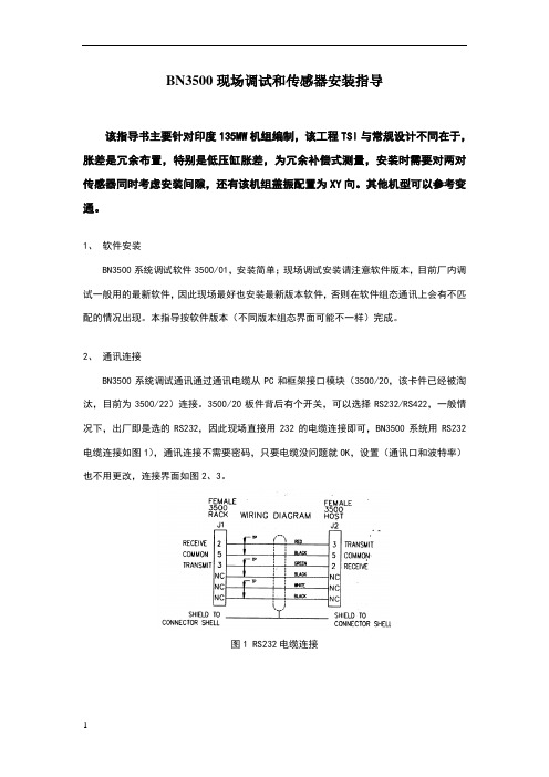
3500/20板件背后有个开关,可以选择RS232/RS422,一般情况下,出厂即是选的RS232,因此现场直接用232的电缆连接即可,BN3500系统用RS232电缆连接如图1),通讯连接不需要密码,只要电缆没问题就OK,设置(通讯口和波特率)也不用更改,连接界面如图2、3。
图1 RS232电缆连接图2 通讯连接界面一图3 通讯连接界面二3、模块组态以及组态下载按TSI机箱框架实际槽位布置新建一个框架配置组态(只针对同一机箱配置,不同机箱需要不同框架配置组态),该配置也可以直接从TSI框架接口模块中上传至PC上(因为出厂前,TSI在厂内已经完成调试工作),如图4。
图4 上传机箱配置到PC上右键框架中任何一个模块,即可对其进行组态,右键菜单如图5:图5 卡件组态卡件右键OPTIONS,设置卡件参数,包括传感器选型,测量类型,通道选择等;卡件右键SETPOINTS设置报警停机值;卡件右键VERIFICATION为卡件通道显示(间隙电压和间隙值),当PC与框架接口模块处于连接状态,并且传感器安装连接上时,可以在这个画面中检测传感器间隙值显示;同时在该画面中可以显示该模块OK状态,通道OK状态和传感器所处的状态(间隙值,电压值,停机报警状态变化),界面如图6。
Eurotherm 3500系列高级过程控制器用户指南说明书

The latest range of advanced process controllers from Eurotherm provide precision control of temperature and a host of other process variables together with an abundance of advanced options making it the most adaptable product in its class.The emphasis is on flexibility yet the 3500 controllers still maintain ease of use. A simple ‘Quick Start’ process is used to configure all the basic functions essential to controlling your process. This includes input sensor type, measurement range, control options and alarms making ‘Out the Box’operation truly achievable. More advanced features are configured using a PC based graphical configuration tool enabling users to pick function blocks from a library then connect them together using soft wiring.The large 5-digit display provides a clear and unambiguous indication of the process value. A four-line message centre provides custom or standard views of important information to the user while vertical and horizontal bargraphs provide at a glance visual indication of the process. OEM Security enables a user to protect their intellectual property by preventing unauthorised cloning of the configuration.Dual loopTwo independent PID loops make the 3500 ideal for interactive processes such as those found in carburising furnaces, environmental chambers and autoclaves. The loops may also be ‘soft’ wired together in creative ways to create cascade, ratio or other intelligent control strategies.Control Optimise Simplify • 2 PID loops•50 Programs•Precision PV input•Carbon potential•Maths/logic/timers•Custom user interface•Recipes•Digital communications–Modbus RTU Master and– Slave– Ethernet Modbus TCP– Profibus DP network– DeviceNet® network•OEM Security•Multi-language support (English, French, German, Spanish and Italian)3500 SeriesDual Loop Controller/ProgrammerImprove process efficiency, product quality and minimise wasteSetpoint programmerHeat treatment and other processes often requirethe ability to change setpoints with time. The dualloop 3500 has two programmers which can beconfigured as synchronised or independentprograms. 50 programs with up to two channelscan be stored with a total of 500 segments.Input/output flexibilityA range of plug-in I/O modules caters forindividual application requirements minimisingstock and spares holding. A total of sixteenmodule types, including relay, logic, triac andanalogue, are available to fit into either three slotson 3508 or six slots on 3504.2| 3500 Series Data SheetCarbon potentialThe 3500 calculates carbon potential from measuring both the oxygen concentration and temperature of a furnace using a zirconia probe. This enables a dual loop 3500 to be used to control both carbon potential and temperature in an atmosphere controlled furnace.Customised solutionsThe 3500 is more than just a process controller. It also provides a selection of application blocks including maths, logic and timing functions offering the ability to develop custom solutions and create cost effective machine controllers. The custom User Page feature allows an operator to view current information in a style most suitable to the process and terminology of the industry.CommunicationsThe 3500 is designed to integrate seamlessly withprogrammable logic controllers and other supervisory systems.A wide range of serial communication options are catered for including EIA232 and EIA485 using the Modbus RTU protocol along with Profibus DP and DeviceNet. Ethernet connectivity is achieved using the Modbus TCP protocol.RecipesUsing a PC tool recipes can be created that can be used to change the operating parameters of the 3500 simply by selecting a new recipe via the HMI. This is very useful where multiple products are processed using the same controller but require different parameters to be set.Infrared configuration adaptorCommunications to the 3500 can be achieved by using an infrared adaptor.Clipping onto the front fascia it provides Eurotherm iToolscommunications allowing configuration and commissioning to be performed without the need to access the rear terminals of the controller.Eurotherm iTools Graphical Wiring EditorThe GWE is anextremely easy way to create applications. It allows users to select the function blocks they wish to use in theirapplication then connect them together using ‘Soft Wiring’. The GWE gives the user a pictorial view of exactly what hehas configured and can also be used to monitor runtime conditions.IO ExpanderExtra IO can be provided by the IO Expander. Options are available for 10in 10out and 20in 20out.SpecificationEnvironmental performanceTemperature limits: Operation:0 to 50°C Storage:–10 to 70°CHumidity limits: Operation:5 to 95% RH non condensing Storage:5 to 95% RH non condensing Panel sealing: IP65, NEMA12Vibration: 2g peak, 10 to 150Hz Altitude:<2000 metresAtmospheres:Not suitable for use in explosive or corrosive atmosphere*Electromagnetic compatibility (EMC)Emissions and immunity:BS EN61326Suitable for domestic, commercial and light industrial as well as heavy industrial.(Domestic/light (Class B) emissions. Industrial (Class A) environmental immunity emissions.With Ethernet module fitted product only suitable for Class A emissionsElectrical safetyBS EN61010:Installation cat. II; Pollution degree 2INSTALLATION CATEGORY IIThe rated impulse voltage for equipment on nominal 230V mains is 2500V .POLLUTION DEGREE 2Normally, only non-conductive pollution occurs. Occasionally, however, a temporary conductivity caused by condensation shall be expected.PhysicalDimensions:3508: 48W x 96H x 159Dmm 3504: 96W x 96H x 159Dmm Weight: 3508: 400g 3504: 600gPanel:3508: 1/8 DIN mounting 45W x 92Hmm cut-out 3504: 1/4 DIN mounting 92W x 92Hmm cut-out Panel depth:Both: 148mmOperator interfaceType:STN LCD with backlight Main PV display:3508: 4 1/2 digits. green 3504: 5 digits, greenMessage display: 3508: 8 character header and 3 lines of 10 characters 3504:16 character header and 3 lines of 20 characters Status beacons: Units, outputs, alarms, program status, program events, active setpoint, manual, remote SP Access levels:3 operator plus config. Password protectedPower requirementsSupply voltage:100 to 230V ac, ±15%,48 to 62Hz, max 20W (3508 15W)24V ac, –15%, +10%.24V dc, –15% +20% ±5% ripple voltage max 20W (3508 15W)Interrupt protection: Standard: Holdup >10ms at 85V RMS supply voltageLow voltage: Holdup >10ms at 20.4V RMS supply voltageInrush current:High Voltage (VH): 30A duration <100μS Low Voltage (VL): 15A duration <100μSUser pageNumber: 8Parameters: 64 totalFunctions: Text, conditional text, values, bargraph Access level:User selectable (level 1, 2 or 3)Back up BatteryThis instrument is fitted with a back up battery which should be changed between 6 and 10 years of use.A record of instrument configurations or, preferably, a clone file should be maintained. This can be re-loaded following a battery change or other maintenance.The battery is not serviceable: contact your local service centre to make suitable arrangements. For further information see User Manual HA027988 at ApprovalsCE, cUL listed (file E57766), Gost. Suitable for use in Nadcap and AMS2750Eapplications under System Accuracy Test calibration conditionsInfrared clipconnected to the 3504No of ports: 2 modules can be fittedSlot allocation: Modbus RTU or I/O expander only in J commsportSerial communications optionProtocols: Modbus RTU SlaveProfibus DPDeviceNetEI-Bisync (818 style mnemonics)Modbus RTU master broadcast (1 parameter)I/O ExpanderIsolation: 264V ac, double insulated Transmission standard: EIA232, EIA485, CAN (DeviceNet), Profibus Ethernet communications optionProtocol: Modbus TCP, 10baseTIsolation: 264V ac, double insulated Transmission standard: 802.3Features: DHCP client, 4 simultaneous mastersCalibration accuracy: <±0.1% of reading ±1LSD (Note 1) Sample rate: 9Hz (110ms)Isolation: 264V ac double insulation from the PSU andcommunicationInput filter: Off to 59.9s. Default 1.6sZero offset: User adjustable over full rangeUser calibration: 2-point gain & offset ThermocoupleRange: Uses 40mV and 80mV ranges dependent ontypeTypes: K, J, N, R, S, B, L, T, C, PL2, customdownload x 2Resolution: 16 bitsLinearisation accuracy: <0.2% of readingCold junction compensation: >40:1 rejection of ambient changeExternal reference of 0°C, 45°C and 50°C Cold junction accuracy: <±1°C at 25°C ambientResistance thermometerRange: 0-400Ω (–200°C to +850°C) Resistance thermometer types: 3-wire Pt100 DIN 43760Resolution (°C): <0.050°C with 1.6sec filter Resolution: 16 bitsLinearity error: <±0.03% (best fit straight line) Calibration error: <±0.310°C/°C, ±0.023% of measurementat 25°CDrift with temperature: <±0.010°C/°C, ±25ppm/C of measurementfrom 25°CCommon mode rejection: <0.000085°C/V (maximum of 264V rms) Series mode rejection: <0.240°C/V (maximum of 280mV pk-pk) Lead resistance: 0Ω to 22Ω, matched lead resistanceInput impedance: 100MΩBulb current: 200μA40mV RangeRange: –40mV to +40mVResolution (μV): <1.0μV with 1.6sec filterResolution: 16 bitsLinearity error: <0.003% (best fit straight line) Calibration error: <±4.6μV, ±0.053% of measurement at 25°C Drift with temperature: <±0.2μV/C, ±28ppm/C of measurementfrom 25°CCommon mode rejection: >175dB (maximum of 264V rms)Series mode rejection: >101dB (maximum of 280mV pk-pk)Input leakage current: ±14nAInput impedance: 100MΩ80mV RangeRange: –80mV to +80mVResolution (μV): <3.3μV with 1.6sec filterResolution: 16 bitsLinearity error: <0.003% (best fit straight line) Calibration error: <±7.5μV, ±0.052% of measurement at 25°C Drift with temperature: <±0.2μV/°C, ±28ppm/C of measurementfrom 25°CCommon mode rejection: >175dB (maximum of 264V rms)Series mode rejection: >101dB (maximum of 280mV pk-pk)Input leakage current: ±14nAInput impedance: 100MΩ2V RangeRange: –1.4V to +2.0VResolution (mV): <90μV with 1.6sec filterResolution: 16 bitsLinearity error: <0.015% (best fit straight line)Calibration error: <±420μV, ±0.044% of measurement at 25°C Drift with temperature: <±125μV/C, ±28ppm/C of measurementfrom 25°CCommon mode rejection: >155dB (maximum of 264Vrms)Series mode rejection: >101dB (maximum of 4.5V pk-pk)Input leakage current: ±14nAInput impedance: 100MΩ10V RangeRange: –3.0V to +10.0VResolution (mV): <550μV with 1.6sec filterResolution: 16 bitsLinearity error: <0.007% of reading for zero source resistance.Add 0.003% for each 10Ω of source plus leadresistanceCalibration error: <±1.5mV, ±0.063% of measurement at 25°C Drift with temperature: <±66μV/C, ±60ppm/C of measurementfrom 25°CCommon mode rejection: >145dB (maximum of 264V rms allowed) Series mode rejection: >92dB (maximum of 5V pk-pk allowed)Input impedance: 62.5kΩ to 667kΩ depending on input voltageNotes1.Calibration accuracy quoted over full ambient operating range and for all input linearisation types2. Contact EurothermIsolation: Not isolated from each other. 264V ac doubleinsulation from the PSU and communication InputRating: Voltage level: Closed 0 to 7.3V dcOpen 10.8 to 24V dcContact closure: Open >1200ΩClosed <480ΩFunctions: Includes program control, alarm acknowledge,SP2 select, manual, keylock, RSP select,standbyOutputRating: 18V dc >9mA <15mAFunctions: Includes control outputs, alarms, events, statusRating: Min 1mA @ 1V dc, Max 2A @ 264V ac resistive1,000,000 operations with external snubber Isolation: 264Vac double insulationFunctions: Includes control outputs, alarms, events, statusIO Modules 3508: 3 modules can be fitted3504: 6 modules can be fittedIO Expander: 20 Digital inputs, 20 relay outputsCalibration accuracy: ±0.2% of reading ±1LSDSample rate: 9Hz (110ms)Isolation: 264V ac double insulationInput filter: Off to 59.9s. Default 1.6sZero offset: User adjustable over full rangeUser calibration: 2-point gain & offsetFunctions: Includes process input, remote setpoint,power limitThermocoupleRange: –100mV to +100mVTypes: K, J, N, R, S, B, L, T, C, PL2, custom Resolution (μV): <3.3μ****************Effective resolution: 15.9 bitsLinearisation accuracy: <0.2% of readingCold junction compensation: >25:1 rejection of ambient changeExternal reference of 0°C, 45°C and 50°C Cold junction accuracy: <±1°C at 25°C ambient3500 Series Data Sheet | 3Resistance thermometerRange: 0-400Ω (–200°C to +850°C) Resistance thermometer types:3-wire Pt100 DIN 43760Resolution (°C): <±0.08°C with 1.6sec filterEffective resolution: 13.7 bitsLinearity error: <0.033% (best fit straight line) Calibration error: <±(0.4°C +0.15% of reading in °C)Drift with temperature: <±(0.015°C +0.005% of reading in °C) per °C Common mode rejection: <0.000085°C/V (maximum of 264V rms) Series mode rejection: <0.240°C/V (maximum of 280mV pk-pk) Lead resistance: 0Ω to 22Ω, matched lead resistanceBulb current: 300μA100mV RangeRange: –100mV to +100mVResolution (μV): <3.3μV with 1.6s filter timeEffective resolution: 15.9 bitsLinearity error: <0.033% (best fit straight line) Calibration error: <±10μV, ± 0.2% of measurement at 25°C Drift with temperature: <±0.2μV + 0.004% of reading per °C Common mode rejection: >146dB (maximum of 264V rms)Series mode rejection: >90dB (maximum of 280mV pk-pk)Input leakage current: <1nAInput impedance: >100M2V RangeRange:–0.2V to +2.0VResolution (μV): 30uV with 1.6s filter timeEffective resolution: 16.2 bitsLinearity error: <0.033% (best fit straight line) Calibration error: <±2mV + 0.2% of readingDrift with temperature: <±0.1mV + 0.004% of reading per °C Common mode rejection: >155dB (maximum of 264Vrms)Series mode rejection: >101dB (maximum of 4.5V pk-pk)Input leakage current: <10nAInput impedance: >100M10V RangeRange: –3.0V to +10.0VResolution (μV): <200μV with 1.6sec filterEffective resolution: 15.4 bitsLinearity error: <0.033% (best fit straight line) Calibration error: <±0.1mV + 0.02% of reading per °CDrift with temperature: <± 0.1mV + 0.02% of reading per °C Common mode rejection: >145dB (maximum of 264V rms)Series mode rejection: >92dB (maximum of 5V pk-pk)Input impedance: >69kΩType: Single channelResistance: 100Ω to 15kΩExcitation: 0.5V dc supplied by moduleIsolation: 264V ac double insulationFunctions:Includes valve position and remote setpointType: Single channelRating: 0-20mA <600Ω0-10V dc >500ΩAccuracy: <±2.5%Resolution: 10 bitsIsolation: 264V ac double insulationType: Single channelRating: 0-20mA <600Ω0-10V dc >500ΩAccuracy: <±0.5%Resolution: 11 bitsIsolation: 264V ac double insulationType: Dual channelRating Output: 4-20mA dc, <1KΩTxPSU: 24V dc, 22mAIsolation: 264V ac double insulation between channels Functions: Either channel can be control output or TxPSU Accuracy: <±1%Resolution: 11 bits Module types: Triple contact closure, triple logic level Isolation: No channel isolation. 264V ac double insulationfrom other modules and systemRating;Voltage level: Open –3 to 5V dc @ <-0.4mA***********************Contact closure: Open >28kΩClosed <100ΩFunctions: Includes program control, alarm acknowledge,SP2 select, manual, keylock, RSP select,standbyModule types: Single channel, triple channelIsolation: No channel isolation.264V ac double insulation from other modulesand systemRating Single: 12V dc >20mA <29mATriple: 12V dc >9mA <12mAFunctions: Includes control outputs, alarms, events, statusModule types: Single channel Form A, Single channelForm C, dual channel Form AIsolation: 264V ac double insulationRating: Min 100mA @ 12V dc, Max 2A @264V ac resistiveMin 400,000 (max load) operations withexternal snubberFunctions: Includes control outputs, alarms, events, statusModule types: Single channel, dual channelIsolation: 264V ac double insulationRating: <0.75A @ 264V ac resistiveFunctions: Includes control outputs, alarms, events, statusType: Single channelIsolation: 264V ac double insulationRating: 24V dc @ 20mAType: Single channelIsolation: 264V ac double insulationBridge voltage: Software selectable 5V dc or 10V dc Bridge resistance: 300Ω to 15kΩInternal shunt resistor: 30.1Ω @0.25%, used for calibration of 350Ωbridge at 80%Type:20 I/O: 4 Form C relays, 6 Form A relays,10 logic inputs40 I/O: 4 Form C relays, 16 Form A relays,20 logic inputsIsolation: 264V ac double insulation between channels Ratings: Relay: Min 100mA @ 12V dc,Max 2A @ 264V ac resistiveLogic Input: Open -3 to 5V dc @ <–0.4mA*********************** Communications: Using EX comms module in comms slot JControlNumber of loops: 2Loop update: 110msControl types: PID, OnOff, VP, Dual VPCooling types: Linear, fan, oil, waterModes: Auto, manual, forced manual, control inhibit Overshoot inhibition: High and low cutbacksNumber of PID sets: 3, selectable on PV, SP, OP, On Demand,program segment and remote input Control options: Supply voltage compensation, feedforward,output tracking, OP power limiting, SBR safeoutputSetpoint options: Remote SP with trim, SP rate limit, 2ndSetpoint, tracking modes4| 3500 Series Data SheetSetpoint programmerProgram function: 50 programs, max 500 segments Program names: User defined up to 16 charactersNo of profile channels: 2 (1 if single loop)Operation:Full or partially synchronisedEvents: 8 per channel (8 when fully synchronised)1 timed event, 1 PV eventSegment types: Rate, dwell, time, call, goback and wait Digital inputs: Run, Hold, Reset, RunHold,RunReset, Adv Seg,Skip SegServo action: Process value, setpointPower failure modes: Continue, ramp, resetOther functions: Guaranteed soak, holdback, segmentuser values, wait inputs, PV hot start Process alarmsNumber: 8Type: High, low, devhi, devlo, devband Latching: None, auto, manual, eventOther features: Delay, inhibit, blocking, display message,3 priority levelsDigital alarmsNumber: 8Type: PosEdge, negEdge, edge, high, low Latching: None, auto, manual, eventOther features: Delay, blocking, inhibit, display message,3 priority levelsZirconiaNumber: 1Functions: Carbon potential, dewpoint, %O2 LogO2,probe mVSupported probes: Barber Colman, Drayton, MMICarbon, AACC,Accucarb, SSI, MacDhui, BoschO2,BoschCarbonGas reference: Internal or remote analogue inputProbe diagnostics: Clean recovery time, impedance measurement Probe burn-off: Automatic or manualOther features: Sooting alarm with tolerance setting, PV HumidityNumber: 1Functions: Relative humidity, dewpoint Measurement: Psychrometric (wet & dry) inputs Atmosphere compensation: Internal or remote analogue inputOther features: Psychrometric constant adjust RecipesNumber:8Parameters: 24 per recipeLength of name: 8 CharactersSelection: HMI, comms, strategy Transducer calibrationNumber: 2Type: Shunt, load cell, comparisionOther features: AutotareCommunication tablesNumber: 250Function: Modbus remapping (indirection)Data formats:Integer, IEEE (full resolution) Application blocksSoft wiring: Orderable options of 30, 60 120 or 250 User values: 16 real numbers with decimal point2 IP maths: 24 blocks, add, subtract, multiply, divide,absolute difference, max, min, hot swap,sample and hold, power, square root,Log, Ln, exponential, switch2 IP logic: 24 blocks, AND, OR, XOR, latch, equal,not equal, greater than, less than, greaterthan or equal to, less8 IP logic: 2 blocks. AND, OR, XOR8 IP multiplexor: 4 blocks. 8 sets of 8 values selected byinput parameter8 IP multiple IP: 3 blocks, average, min, max sumBCD Input: 2 blocks, 2 DecadesInput monitor: 2 blocks, max, min, time above threshold 16 Pt linearisation: 2 blocks, I6-point linearisation fit Polynomial fit: 2 blocks, characterisation by Poly Fit table Switchover: 1 block, smooth transition between 2 values Timer blocks: 4 blocks, OnPulse, OnDelay, OneShot,MinOn TimeCounter blocks: 2 blocks, Up or down, directional flag Totaliser blocks: 2 blocks, alarm at threshold valueReal time clock: 1 block, day & time, 2 time based alarms3500 Series Data Sheet | 56| 3500 Series Data SheetOrder Code Hardware/options codingBasic ProductNotes1. Only available with the Profibus Controller2. I/O slots 4, 5 and 6 are only available on the 35043. Provides Valve Position option in Heat/Cool applications. Single channel VP included as standard4. If standard config is selected an instrument without configuration will be supplied.5. If C or F units are selected they must be the same for both loops. If C or F are not selected for Loop 1they cannot be selected for Loop 2.6. CH1 = Heat, CH2 = Cool.3500 AccessoriesTable 1Configuration coding3500 Series Data Sheet | 7Document Number HA029045 Issue 8March 2016 Scan for localcontactsEurotherm by Schneider Electric, the Eurotherm logo, Chessell, EurothermSuite,M ini8, Eycon, Eyris, EPower, EPack, nanodac, piccolo, versadac, optivis, Foxboroand Wonderware are trademarks of Schneider Electric, its subsidiaries and affiliates.All other brands may be trademarks of their respective owners.All rights are strictly reserved. No part of this document may be reproduced, modified,or transmitted in any form by any means, nor may it be stored in a retrieval systemother than for the purpose to act as an aid in operating the equipment to which thedocument relates, without the prior written permission of Eurotherm Limited.Eurotherm Limited pursues a policy of continuous development and productimprovement. The specifications in this document may therefore be changed withoutnotice. The information in this document is given in good faith, but is intended forguidance only.Eurotherm Limited will accept no responsibility for any losses arising from errors inthis document.©CopyrightEurothermLimited216Eurotherm LimitedFaraday Close, Durrington,Worthing, West Sussex, BN13 3PLPhone: +44 (01903) 268500Fax: +44 (01903) 265982/worldwide。
3500本特利使用说明

有关萧山电厂的3500本特利使用说明我厂于2005年5月在#1机组上安装了3500本特利表(由3300改造) BNC System Installed Date:本特利公司系统安装日期:2005年5月BNC System Construct and It’s P/N, S/N:本特利公司系统构成及编号,系列号:3500监测系统1套:3500/15 2块, 3500/22 1块, 3500/25 1块, 3500/42 3块,3500/45 1块, 3500/32 2块, 3500/33 1块, 3500/92 1块Installation/Configuration/Calibration/Inspection Procedure:安装/组态/校验/检测步骤:1, 3500系统组态1), 槽2的CH1是键相器, 1齿, 0 - 5000rpm。
键相探头的安装电压为-10Vdc,不能对准键槽.2), 槽3和槽4的8个通道组态为绝对振动,相对振动传感器为3300 8mm,瓦振传感器9200。
量程0 – 500um pp, 绝对振动报警1为125um pp, 报警2为250um pp。
槽3: ch1= VB1R, ch2= VB2R, ch3= VB1S, ch4= VB2S槽4: ch1= VB3R, ch2= VB4R, ch3= VB3S, ch4= VB4S3), 槽5的CH1和CH2组态为轴位移,7200 11mm传感器,量程为±2mm, 报警1为±1.0mm, 报警2为±1.2mm 。
轴位移正方向为远离探头。
轴位移1和2的安装零位电压为-12Vdc。
Ch1=RP1, Ch2=RP24), 槽5的CH3组态为偏芯, 峰峰值量程0 – 500um pp.电名为RX. 安装零位电压为-10Vdc。
5), 槽6 CH1组态为高缸胀差, 量称为-2.0 -0- +8.0mm, 报警1为+6.0mm, -1.0mm。
