电子信息工程外文翻译外文文献英文文献文献翻译
电子信息工程 外文翻译 外文文献 英文文献 文献翻译

Technology and Application of Fieldbus Control System ---------IntelligentEquipment & Measurement And Control System Based on DeviceNetPromoted by the new technological revolution that automation control technology is tending digitization and internet in the field of automation industry, Shanghai Aton Electric Co., Ltd. developed Intelligent Equipment & Measurement And Control System Based on DeviceNet as a high and new technology industrialization model project. It was a state hi-tech development project of 2000 and was approved by the State Committee of Technology. Shanghai Aton Electric Co., Ltd. constructed production line of intelligent controller of pump and valve, relying on Shanghai Electric (Group) Corporation; constructed measurement and control system FCS R&D center of intelligent controller of pump and valve and built up mass production R&D basis, cooperating with Shanghai Jiaotong University and Shanghai University; constructed FCS remote diagnosis and service center of intelligent controller of pump and valve; constructed FCS training center of intelligent controller of pump and valve; founded mass production R&D basis along with the Rockwell Laboratory of Shanghai Jiaotong University and CIMS Center.1 Summary(1)Fieldbus control system is a system applied to field of production and microcomputerized measurement control equipment to realize both-way multinode serial communications. It is also called low-level control network for open, digital and multiplespot communications.Application: Flow Control System of Manufacturing; Process Control System; Traffic Control & Management; Building Automation. Features: Fieldbus control system is low-level low-bandwidth digital communication and control network in industrial system as well as open system connecting microcomputerized appearance. Intelligent instrument and controller are equal to microcomputer. They make up network with Fieldbus control system as the links to complete digital communication and other tasks.(2)Difference between FCS and DCS,FCS is updated control system after DCS integrated with digital control system and distributing control system. It solves the problem that in traditional DCS, devices made by different manufacturers cannot be connected. They can't realize exchange and operation to organize an network system with wider range of information sharing. It conquers the defect that special closed system for network should be used for communication in DCS to realize various functions of integrated automation. It turns the distributing structure combiningconcentration with deconcentration in DCS into new-type full distributing structure. It releases the control function to the field thoroughly and makes it possible to realize basic control function by means of fieldbus equipment itself. FCS breaks the traditional structure form of control system. The traditional analog control system adopts one-to-one equipment tie-wire and puts up connections respectively according to control loop. FCS adopts intelligent field equipment to place the control module, all input/output modules that used to be in the control chamber of DCS into field equipment. Since field equipment has ability to communicate, the field measuring and transferring instruments can transfer signals to actuating mechanism such as valve directly. Its control function can be fulfilled directly on the spot independent of the computer or control meter in the control chamber, which realizes thorough decentralized control.FCS adopts digital signals to replace analog signals so that multiple signals (including multiple operating parameter values, device status and failure information) can be transferred on a pair of cables. Meanwhile, it can give power supply to several devices. No switched block for analog/digital or digital/analog is needed besides fieldbus.(3)Characteristics of FCS●Open System;●Interoperability;● replace ability of devices made by different manufacturers.● Intelligentize and Autonomy;●Field equipment completing basic functions of automatic control.●Decentralized System Structure;●Field Adaptability;●Relatively Strong Interference Killing Feature and Safety●Intelligentized local equipment can save investment and quantity of hardware●Saving installation expenses and cables●Saving daily maintenance expenses●Enhancing accuracy and reliability of system●Enhancing initiativeness of system integration for users(4)Development Background and Trend of Fieldbus Control System,With the rapid development of computer and computer network, FCS has been rapidly developed as the interlinked communication network between the field intelligentdevices in the field of process automation, building and traffic etc. Because FCS meets the needs that industrial control system is developing in the way of decentralization, network and intellectualized, it has become the focus of global industrial automation and been universally concerned by the whole world. FCS has caused great revolutions on the aspects of system structure and function system for the current production of automation instrument, distributing control system and programmable controller. It is predicted that FCS will be the general trends in a very long time in the future fore sure.2 APPLICATION OF RELAYThe product reliability generally refers to the operating reliability. It is defined as: the ability of accomplishing the specified function under prescribed conditions and in prescribed time. It consists of intrinsic reliability and application reliability. The intrinsic reliability is determined by product designing and manufacturing technique, and the application reliability is concerned with the correct application of users and the services provided by the manufacturer before and after selling. When using relay, the user should pay attention to the following items.2.1 Coil applied voltageIt is best to choose the coil applicative voltage according to the rated voltage in design, or choose the voltage according to the temperature rising curve. Using any coil voltage that is less than the rated voltage will affect the operation of the relay. The coil operating voltage refers to the voltage that is applied between the coil terminals. The voltage value between the two terminals must be guaranteed, especially when using enlargement circuit to energize the coil. Whereas, it will also affect the relay characteristics if the applied voltage exceeds the highest rated voltage. Exorbitant voltage will bring exorbitant coil temperature rising, especially in high temperature ambient. Exorbitant temperature rising will damage the insulating material and affect the working safety of relay. For magnetic latching relay, energizing (or return) pulse width should not less than 3 times of the operating (or return) time, otherwise, the relay would be left on the middle-position state. When using solid-state components to energize the coil, the components dielectric strength must be above 80V, and the leakage of current must be as little as possible to ensure the relay to release.Energizing power source: Under 110% of the rated current, the adjusting ratio of the power source is less than 10% (or the output impedance is less than 5% of the coilimpedance), the wave voltage of the DC power source is less than 5%. The AC wave is sine wave; the waviness coefficient is between 0.95~1.25; wave distortion is within ±10%; the frequency change is within±1Hz or ±1% of the specified frequency (choosing the bigger value). The output power should not less than coil power consumption.2.2 Transient suppressionAt the moment when the coil power is stopped, peak-inverse voltage that is more than 30 times of the coil rated voltage is produced on the coil, which is harmful to the electronic circuit. Generally, the peak-inverse voltage is suppressed by transient suppression(cutting-peak)diode or resistance to limit the peak-inverse voltage within 50V. But the diode in parallel connection will delay3~5 times of the release time. If the request of the release time is high, a suitable resistance in series can be putted with and at one end of the diode.The power supply to relays in parallel connection and series connection,When several relays in parallel connection are supplied, the relay that the peak-inverse voltage is higher will release power to the relays that the peak-inverse voltage is lower. The release time of the relay will delay. So the relays in parallel connection should be controlled separately to eliminate mutual influence.The relays with different coil resistance and power can’t be used in series, otherwise, t he relay that the coil current is higher in the series circuit can’t operate reliably. Only the relays of the same specification can be used in series, but the peak-inverse voltage will be increased and the peak-inverse voltage should be suppressed. Resistance in series can be used to bear the part voltage that exceeds the rated voltage of the coil according to the ratio of the divided voltage.2.2.1 Contact loadThe load applied to the contacts should be accordant to the rated load and characteristics of the contacts. A load that is not applied according to the rated value range will cause problem. The relay that is only suitable for DC load can’t be used in AC occasions. The relay that can switch 10A load can’t always reliably operate in low level load (less than 10m A×6A) or in dry circuit occasions. The relay that can switch single-phase AC power source isn’t always suitable to switch two single-phase AC loads that aren’t synchronous; the relay that is only specif ied to switch the load of AC 50Hz(or 60Hz)can’t be used to switch AC load of 400Hz.2.2.2 Parallel and series connection of contactsThe contacts used in parallel connection can’t increase the load current, because the operating times of several sets of contacts are absolutely different; that is to say, there is still only a set of contacts switching the increased load. This would damage or weld the contacts and make the contacts can’t close or open. The parallel connection of the contacts can decrease t he misplay of “break”. But the parallel connection of the contacts would increase the misplay of “freezing”. Because the misplay of “break” is the main pattern of invalidation of contacts, the parallel connection can increase the reliability and can be used on the pivotal part of equipments. But the applied voltage should not exceed the highest operating voltage of the coil and should not less than 90% of the rated voltage, otherwise, the coil life and the applicative reliability would be damaged. The series connection of the contacts can increase the load voltage. The amount of the contact sets is equal to the times that the load voltage can be increased. The series connection of contacts can decrease the misplay of “freezing”, but it would increase the mis play of “break”. Anyway, when using redundant technology to increase the operating reliability of contacts, the characteristics and size and the failure mode of load must be considered.2.2.3 Switching speedThe switching speed should not exceed the reciprocal of 10 times of the sum of operating and release time (times/s), otherwise, the contacts can’t switch on steadily. Magnetic latching should be used under the pulse width specified in the technique criterion, or the coil may be damaged.3 RVT DISTRIBUTING ELECTRICITY INTEGRATE TESTAPPARATUSBasic functionMeasure asupervision:Three mutually electric voltage/electric current/ power factor with a great achievement/ power without a great achievement/electricity with a great achiverment/electricity/homophonic-wave electric voltage/ homophonic-wave electric/ current Day electric voltage/ electric current biggest and minimum value/fire for the failure Electric voltage over top, the limit/ lack mutually of time homophonic-wave analyzes is up to 13 times.The data is stored for 2 months.The data communicateRS232/485 communicating connect,The way in communicating can adopt the spot communicating or the long range communicating.,Possible to settle invoke orthe solid hour invokes, responding to the modification and long ranges control of the parameter.Without power compensationTaking physics measures as the power factor without a great achievement,the power factor with a great achievement and the dull place without power compensation;Y+ the combination method of the △,Y+ the △connects the line method,Y+ △ , Y, the △ connects the line method.Data managementAccording to WINDOW98 operation terrace, data in communication automatically reports born statement, curve and pillar form diagrams.Circulation of the protectionWhen the charged barbed wire net of mutually electric voltage over press, owe to press, and a super limit hour fast cut off in expiation of capacitor,When the charged barbed wire net lacks mutually or super limit in the preface of zero hour fast cut off in expiation of capacitor.screen manifestationChinese operation interface,Adopt 128*64 the back light liquid crystal display.The solid hour shows the charged barbed wire net relevant parameter.view manifestation to place the parameter.现场总线控制系统的技术和应用随着新的科学技术革命的出现,在自动化工业领域中,自动控制技术的发展趋向于数字化和网络互联化。
电子信息工程外文翻译 外文文献 英文文献

电子信息工程电路编程中的AT89C51单片机译文标题电路编程中的AT89C51单片机AT89C51 In-Circuit Programming 原文标题作者Robert W.Sparks等译名国籍美国斯帕克等W.罗伯特Atmel Corporation原文出处摘要本应用说明的是ATMEL公司AT89C51的电路可编程闪存的微控制器。
为在电路可编程AT89C51的应用提出了与应用程序相关的例子,它的修改要求支持在线编程。
这种方法显示在该应用程序中的AT89C51单片机可通过商业电话线远程改编。
本应用笔记中描述的电路,仅支持5伏电压下编程,需要使用一个AT89C51-XX-5。
标准A T89C51的需要12伏电压。
该应用程序的软件可从ATMEL下载。
总论当不在进行程序设计的时候,在电路设计中的AT89C51设计将变得透明化。
在编程期间必须重视EA/VPP这一脚。
在不使用外部程序存储器的应用程序中,这脚可能会永久接到VCC。
应用程序使用的外部程序存储器要求这一脚为低电平才能正常运行。
RST在编程期间必须为高电平。
应该提供一种方法使得电路通入电源以后,使RST代替主要的复位电路起到复位的作用。
在编程过程中,PSEN必须保持低电平,在正常运行期间绝不能使用。
ALE/ PRO在编程过程中输出低电平,在正常运行期间绝不能使用在编程过程中AT89C5I / 端口是用于模式应用程序,地址和数据选择的,可能要该控制器从应用的电路隔离。
如何做到这一点取决于应用程序输入端在编程过程中,控制器必须与应用电路的信号来源隔离。
带有三个输出状态的缓冲区在应用程序之间插入电路和控制器,同时在编程时缓冲区输出三种状态。
一个多路复用器用于信号源之间进行选择,适用于任何一方的应用电路或编程控制器电路的信号输出端如果应用的电路可以允许端口在编程过程中的状态变化,则不需要改变电路。
如果应电路的状态,必须事先在编程过程中的保持不变,可能在控制器和应用电路中插入锁存。
电气工程及其自动化专业_外文文献_英文文献_外文翻译_plc方面.
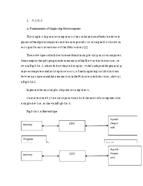
1、外文原文A: Fundamentals of Single-chip MicrocomputerTh e si ng le -c hi p m ic ro co mp ut er i s t he c ul mi na ti on of both t h e de ve lo pm en t of the dig it al com pu te r an d th e in te gr at ed c i rc ui t arg ua bl y t h e tow m os t s ig ni f ic an t i nv en ti on s o f t he 20th c e nt ur y [1].Th es e tow type s of arch it ec tu re are foun d in sin g le -ch i p m i cr oc om pu te r. Som e empl oy the spli t prog ra m/da ta me mo ry of the H a rv ar d ar ch it ect u re , sh ow n in Fig.3-5A -1, oth ers fo ll ow the p h il os op hy , wi del y ada pt ed for gen er al -p ur po se com pu te rs and m i cr op ro ce ss o r s, o f ma ki ng no log i ca l di st in ct ion be tw ee n p r og ra m and dat a me mo ry as in the Pr in ce to n arch ite c tu re , show n i n Fig.3-5A-2.In gen er al ter ms a sin gl e -chi p mic ro co mp ut er i sc h ar ac te ri zed b y t he i nc or po ra ti on of a ll t he un it s of a co mp uter i n to a sin gl e d ev i ce , as sho wn inFi g3-5A -3.Fig.3-5A-1 A Harvard typeFig.3-5A-2. A conventional Princeton computerFig3-5A-3. Principal features of a microcomputerRead only memory (ROM.R OM is usua ll y for the pe rm an ent,n o n-vo la ti le stor a ge of an app lic a ti on s pr og ra m .M an ym i cr oc om pu te rs and m are inte nd e d for high -v ol um e ap pl ic at ions a n d he nc e t h e eco n om ic al man uf act u re of th e de vic e s re qu ir es t h at t he cont en t s o f t he prog ra m me m or y be co mm it t ed perm a ne ntly d u ri ng the man ufa c tu re of ch ip s .Cl ea rl y, thi s im pl ie s a r i go ro us app ro ach to ROM cod e deve l op me nt sin ce cha ng es can not b e mad e afte r manu f a c tu re .Th is dev e lo pm en t proc ess may invo lv e e m ul at io n us in g aso ph is ti ca te d de ve lo pm en t sy ste m wit h a h a rd wa re emu la tio n cap ab il it y as w el l as the use o f po we rf ul s o ft wa re too ls.So me man uf act u re rs pro vi de add it io na l RO M opt i on s by i n cl ud in g in their ra n ge dev ic es wit h (or int en de d fo r use wit h u s er pro gr am ma ble me mo ry. Th e sim p le st of th es e is usu al ly d e vi ce whi ch can op er at e in a micro p ro ce ssor mod e by usi ng som e o f the inp ut /outp u t li ne s as an ad dr es s an d da ta b us fora c ce ss in g ex te rna l mem or y. Thi s t y pe of de vi ce can beh av ef u nc ti on al ly as th e sing le chip mi cr oc om pu te r from whi ch it is d e ri ve d al be it wit h re st ri ct ed I/O and a mod if ied ex te rn al c i rc ui t. The use of thes e d ev ic es is com mo n eve n in prod uc ti on c i rc ui ts wher e t he vo lu me does no tj us ti f y t h e d ev el o pm en t c osts o f c us to m o n -ch i p R OM [2];t he re c a n s ti ll bea s ignif i ca nt saving i n I /O and o th er c h ip s com pa re d to a conv en ti on al mi c ro pr oc es sor b a se d ci rc ui t. Mor e ex ac t re pl ace m en t fo r RO M dev i ce s ca n be o b ta in ed in th e fo rm of va ri an ts w it h 'p ig gy -b ack 'E P RO M(Er as ab le pro gr am ma bl e ROM s oc ke ts or dev ic e s with EPROM i n st ea d o f RO M 。
英文文献科技类原文及翻译(电子电气自动化通信…)50
目录1译文 (1)2原文 (7)1参考文献译文绿色创想建筑商计划提供了节能解决方案与行业认可的新住房平均相比,绿色畅想建筑商计划旨在降低家用能源和水的想好,减少排放。
该项目创新性地结合了建筑科学和高品质的产品,在帮助建筑商和开发商建造舒适型住房的同时,降低房屋对环境的影响。
随着生活费用的不断上涨,悦来愈多的人开始考虑将环保技术纳入新住房当中。
与行业认可的新住房陪你冠军水瓶相比,依照GE绿色创想建筑商计划所建造的房屋每年客减少20%的能耗与室内用水量,并且使生活用气排放量减少20%。
对于一套面积为2500平方英尺的住房而言,该计划每年可使购房者减少600至1500美元的电费和水费。
自该计划于2007年5月启动以来,整个美国与加拿大的建筑商与开发商纷纷申请建造绿色创想式房屋,其中包括德州西斯顿峡谷们的社区开发商。
按照绿色畅想计划正在开发的首个峡谷么社区被称为Discovery Companies,预计将于2008年夏季开盘。
加拿大的Fi的零售税环保想象住房计划推出在2007年9月,GE加拿大与波尔多发展组织签订计划,决定在位于加拿大阿尔伯他省卡尔加里西部的社区Rocky View实施加拿大首个绿色创想建筑商计划。
这块地区60多年来,一直有当地的一个牧民家庭所有,长期以来除了放养家畜之外始终难以用于其他用途。
迫于地区发展的强大压力,这个家庭决定对这块土地进行开发。
当这家人了解到如何最邮箱的进行地产开发之后,开始认真考虑如何处理这篇土地。
其中,家庭价值、对环境的保护意识以及社区精神都称为了需要考虑的关键问题。
实施证明,将GE的绿色创想建筑商计划与波尔多发展组织的环境可持续发展战略相结合是非常成功的。
规划中的面积为1750英亩的混用型绿色创想建筑商和谐开发项目见那个进行客持续开发,其中包括关于有效实用土地的创新性环保计划。
竣工使,此开放项目将建筑起3500所住房和衣架保健中心、一个27洞国际高尔夫球场、一所学校和一篇商业用地。
电子信息工程专业毕业论文中英文资料外文翻译文献

毕业论文毕业论文中英文对照翻译中英文对照翻译院(系部) 电气工程与自动化 专业名称 电子信息工程Infrared Remote Control SystemAbstractRed outside data correspondence the technique be currently within the scope of world drive extensive usage of a kind of wireless conjunction technique,drive numerous hardware and software platform support. Red outside the transceiver product have cost low, small scaled turn, the baud rate be quick, point to point SSL, be free from electromagnetism thousand Raos etc.characteristics, can realization information at dissimilarity of the product fast, convenience, safely exchange and transmission, at short distance wireless deliver aspect to own very obvious of advantage.Along with red outside the data deliver a technique more and more mature, the cost descend, red outside the transceiver necessarily will get at the short distance communication realm more extensive of application.The purpose that design this system is transmit customer’s operation information with infrared rays for transmit media, then demodulate original signal with receive circuit. It use coding chip to modulate signal and use decoding chip to demodulate signal. The coding chip is PT2262 and decoding chip is PT2272. Both chips are made in Taiwan. Main work principle is that we provide to input the information for the PT2262 with coding keyboard. The input information was coded by PT2262 and loading to high frequent load wave whose frequent is 38 kHz, then modulate infrared transmit dioxide and radiate space outside when it attian enough power. The receive circuit receive the signal and demodulate original information. The original signal was decoded by PT2272, so as to drive some circuit to accomplish customer’s operation demand.Keywords:Infrare dray;Code;Decoding;LM386;Redoutside transceiver1 Introduction1.1 research the background and significanceInfrared Data Communication Technology is the world wide use of a wireless connection technology, by the many hardware and software platforms supported. Is a data through electrical pulses and infrared optical pulse switch between the wireless data transceiver technology.Infrared transceiver products with low cost, small, fast transmission rate, the point-to-point transmission security, not subject to electromagnetic interference and other characteristics that can be achieved between the different products, rapid, convenient and safe exchange and transmission, In short distance wireless transmission have a very distinct advantage.Infrared transceiver products in the portable product of a great role. At present, the world's 150 million piece of equipment used infrared technology in electronic products and industrial equipment. medical equipment and other fields widely used. For example, 95% of the notebook computers on the installation of infrared transceiver interface the majority of the cell phone is also the allocation of infrared transceiver interface. With the exchange of quantitative data, infrared data communications will enable cell phone data transmission more convenient. With infrared data transmission technology matures, perfect, low costs, Infrared Transceiver in short distance communications will be more widely applied.This chapter first describes the infrared transceiver IC design issues to the background and significance. then briefed the infrared data communications technology features and applications, and infrared transceiver product characteristics, domestic and international situation and development trend of the last under infrared remote transceiver system in practical application to establish a task of design orientation.1.2 Infrared Remote ControlTransceiver SystemInfrared remote control system is divided into single-channel and multi-channel remote control. Only a command signal transmission channel, called single-channel remote control system; with more than two instructions signal transmission channel known as a multi-channel remote control system. Relatively simple single-channel remote control, in general, only a launcher directive Key receivers and only one circuit implementation. While in the receiving circuit to add more stable memory circuits that can be activated commands to launch a number of key, so that the receiver circuit multistable memory circuit repeatedly to change the state, to realize many of the functional control, But such a state of change is the order. If we are to achieve an arbitrary control, resort to the use of multi-channel remote control system. Multi-channel remote control can be realized by the object of arbitrary multi-function remote control. As for the choice of several routes and what control methods, according to the actual situation (such as object, operational requirements and cost accounting, etc.) to decide. General infrared remote transceiver system by infrared remote control transmitter signal coding, infrared remote control signal receivers and decoders (or decoder chip MCU) and the external circuit consisting of three parts. Signal transmitter remote control code used to generate pulses of infrared emission-driven output infrared remote control signal, receiver completion of the remote control signal amplification and detection, plastic and demodulation encoding pulse. Infrared remote control coded pulse is going to obtain a continuous serial binary code, and for most of the infrared transceiver system, This serial code as micro-controller of the remote control input signals from the internal CPU completion of the remote control instruction decoder, on the other infrared remote control transceivers, the designers of electronic products, The internal micro-controller of the remote control decoder directive is not accessible.Therefore, people are using infrared encoder / decoder chip and microcontroller developed various generic infrared remote transceiver system, In various equipment infrared signals between the transceiver.Remote transceiver system generally transmitters and receivers is composed of two parts. Launchers from the general direction keys, coded instructions circuit modulation circuit, driving circuit, firing circuit of several parts. When pressed a key, the directive coding circuit, in the corresponding instructions encoded signal, the encoder signal to the carrier modulation, Driven by the power amplifier circuit after circuit fired from the field after firing instructions coded modulation signals. General receiver by the receiving circuit, the amplifier circuit, demodulation circuits, instruction decoder circuit, driving circuit, circuit implementation of several parts. Receiving Circuit will launch vehicles have been coded modulation signal receiving instructions from, and to enlarge evacuation demodulation circuit. Demodulation circuit will have the coding modulation signal demodulation, namely, reduction of signal coding. The instruction decoder to the encoder signal decoding, Driven by the final circuit to drive the implementation of various instructions circuit to control the operation.1.3 infrared remote control transceiver product profiles 1.3.1 infrared remote control transceiver product structure and typeCurrently infrared transceiver in accordance with the mode of transmission rate and can be divided into four categories : Serial mode, the highest rate of 115.2 Kbps; medium-speed model : the highest rate of 0.567 Mbps and 1.152Mbps; High-speed mode : The maximum rate of 16 Mbps.Also according to the size chip power consumption can be divided into low-power consumption and standard two categories, low-power type normally used 3 V power supply, transmission distance closer to about 0 - 30cm, which is commonly used standard 5V power supply, transmission distance away at least 1mabove.1.3.2 infrared remote control transmitters of the status quo at home and abroadInfrared communication technology in the development stage and there are several infrared communication standards, between different standards for infrared equipment can not infrared communication. To have all the infrared equipment to interoperability in 1993 by more than 20 large manufacturers initiated the establishment of an Infrared Data Association (IRDA) unified the infrared communication standards , which is currently widely used in infrared data communication protocols and standards, also known as the IRDA standard.Since 1993 IRDA since the establishment of the Infrared Data Association members have developed to more than 150. IRDA standards of the industry has been widely recognized and supported. Has been developed with the infrared communications equipment have been as many as 100 species. IR module, installed capacity has reached 150 million sets. Although there is also a short distance wireless Bluetooth technology, But in infrared communication technology low cost and broad compatibility advantages, Infrared data communication in the future will still be a very long time inherent short-range wireless data communications fields play an important role.1.3.3 Infrared Transceiver product development trendIn various infrared transceiver products, although the transmission rate, transmission distance and other characteristics, But infrared transceiver products has been towards improving the transmission rate, increase the transmission distance and lower power consumption, expanding launch reception angle of development. In particular, as the technology development and maturity, the means of transmission is moving in the direction of point-to-multipoint. Therefore infrared remote control transceiver products have broader prospects for development.2 Infrared communication of knowledge2.1 infrared ray foundation knowledge2.1.1 infrared outlinedInfrared is actually a kind of electromagnetic wave. From the analysis of various natural component of the electromagnetic wave reflected spectrum is :-ray, x-ray, ultraviolet, visible, infrared, microwave and radio wave. From the viewpoint of form, and they did not seem to, but if the wavelength in descending order, and we will find him all the only visible light spectrum of the entire 0.38 µm - 0.76µm so long little area, and adjacent to the visible light and infrared (including the far infrared, mid-infrared and near infrared foreign) accounts for the spectrum of 0.76 µm - 1000µm of a major. Which micron wavelength range also includes UV, visible, near infrared, mid-infrared and far-infrared, microwave.From the above analysis shows that infrared is a very rich spectrum resources, it currently has in production, life, military, medical, and other aspects have been widely used, such as infrared heating, medical infrared, infrared communication, infrared camera, infrared remote control, and so on. Infrared remote control is the many applications of infrared part of the current household appliances widely used in TV remote control, VCR remote control, VCD remote control, high-fidelity audio remote control, are used infra-red remote control, It allows the control of these appliances have become very easy.2.1.2 infrared propertiesInfrared lies between visible light and microwave a wave, it is with certain clinical characteristics of the wave. In the near-infrared, visible light and its adjacent, it is visible in certain characteristics, such as straight-line transmission, reflection, refraction, scattering, diffraction, can be certainobjects and can be absorbed through the lens of their focusing. In the far-infrared region, owing to its neighboring microwave, it has some characteristics of microwave, If a strong penetrating power and can run through some opaque substances. Since in any object, natural profession, regardless of whether its own luminescence (referring to visible light), as long as the temperature is above absolute zero (-273 ° C), moment will be kept around to infrared radiation. Only higher temperature of objects strong infrared radiation, low-temperature objects infrared radiation weaker. Therefore infrared feature is the greatest common in nature, it is called thermal radiation called thermal radiation. Infrared cameras, infrared night market pyroelectric infrared detectors and some other missiles aiming at is the use of this characteristic of infrared work.Infrared and visible light compared to another characteristic of a variety of colors. As the longest wavelength of visible light is a wavelength of the shortest times (780 nm-380 nm), So is called an octave. And infrared wavelength is the longest shortest wavelength of a times, and the longest wavelength infrared is the shortest wavelength of 10 times, that is, 10 octave. Therefore, if visible light can be expressed as seven colors, infrared may performance 70 colors, showing the rich colors. Infrared smoke through the good performance, which is also one of its features.Because not visible to the infrared, it has little effect on the environment. By the wave infrared rays than the long wavelength radio waves, infrared remote control will not affect the nearby radio equipment. Another wavelength of less than 1.5µm near infrared light, transparent atmosphere in the visible light transmission characteristics much better than, because it close to the visible edge of the red light, linear transmission, reflection, refraction and absorption material and the physical characteristics very similar to visible light. Therefore, it can be used with similar visible focusing lens and other opticaldevices. Because infrared remote control is not as remote as the radio through the barrier to control the object's ability to control, so in the design of household appliances infra-red remote control, wireless remote control as unnecessary, each set (transmitters and receivers) have different frequency or remote coding (Otherwise, wall will control or interference with neighbors household appliances), all similar products in the infrared remote control, The same can control the frequency or coding, and no remote control signal "drop." This universal infrared remote control provides a great convenience. Infrared to visible light, is very subtle and confidentiality, therefore, the security, Alert and other security devices have been widely used. Infrared remote control is simple in structure and easy, low-cost, anti-interference capability, high reliability are a number of advantages, is a close-up remote control, especially in indoor remote control optimized manner.2.1.3 infrared diode characteristicsInfrared is not visible, people here are not aware of. Electronic technology is used infrared light emitting diode (also known as the IR emission diode) to generate infrared. Infrared remote control transceiver is using near-infrared transmission control instructions 0.76µm wavelength of ~ 1. 5µm. Near-infrared remote control as a light source, because there infrared light emitting diodes and infrared receiving device (photodiode. Transistor and PV) and the luminescence peak wavelength of light by the general 0.8µm ~ 0. 94µm. in the near-infrared band, both of the spectrum is the coincidence to a good match, access to higher transmission efficiency and higher reliability. Commonly used infrared diode, and its shape is similar LED light emitting diodes, Its basic circuit shown in figure 2 -2. The triode plans for the switch, when the base added a driving signal, Transistor saturated conduction infrared LED D is also Wizard Link, issued infrared (near infrared about 0.93 µm). D.The pressure drop of about 1.4 V and the current general for 10-20mA. To adapt to the working voltage of the D loop resistance often as a series of infrared diode current limit resistance.When the circuit diagram of the infrared emission control corresponding to the controlled device, the control of the distance and D is proportional to the transmitting power. In order to increase the distance of infrared control, infrared diode D should work on the pulse state that work is the lifeblood of current. Because pulse light (optical modulation) the effective transmission distance and pulse is proportional to the peak current, only maximize peak current Ip, will increase the infrared distance. Ip increase is a way to reduce the pulse duty cycle, that is compressed pulse width τsome TV infrared remote control, its infrared luminescence of the pulse duty cycle of about 1/4-1/3; Some electrical products infrared remote control, its duty cycle of 1 / 10. Decreasing pulse duty cycle also enable low-power infrared LED distance of the greatly increased. Common infrared light emitting diodes, power is divided into small power (1 mW - 10mW). Chinese power (20mW - 50mW) and power (50mW - 100mW more) three categories. Use different power infrared LED, the allocation should be driven by the corresponding power control. Figure 2 -2 by the reflected infrared light-emitting diodes to make produce optical modulation, Drivers only need to add the control of a certain frequency pulse voltage.Infrared transmitter and receiver in the way the two kinds of straight, and the second is reflective. Luminescence pointed straight pipe and tube receiver placed in a relatively controlled and fired on the two ends, a certain distance away from the middle; Reflective means luminescent tube and pipe parallel with the receiving peacetime, without always receiving tube light, luminescence only in possession of the infrared light reflected fromencountered, the receiving tube received from the reflected infrared before work.2.2 infrared communication basic tenets2.2.1 infrared communication PrincipleCommunication is the use of infrared wavelength of 900 nm-infrared waves from 1000 to serve as an information carrier, through infrared technology between the two close communication and confidentiality of information transmitted. Infrared communication system structure include : part launcher, channel, the receiver part.Launcher source letter issued after the binary signal from the high-frequency modulated infrared LED sent, receiving device regard the reception of high-frequency signals from the infrared receiver tube after receiving further demodulation photoelectric conversion of the original information of a mass communication lose way. Afterwards the former Information received after receiving part of the drive circuit connected to the expected completion of the various functions. To which the modulation coding style pulse width modulation (by changing the pulse width modulated signal PWM) and pulse modulation time (through change the pulse train interval time between the modulation signal PPM) two.2.2.2 infrared communication system elements(1) Launches : Currently there is a infrared wireless digital communications system sources of information including voice, data, images. Its methods of work for the launch of the receiver can be divided into different layout LOS way (Light-of-Sight , intracardiac way), diffuse (diffuse) mode. LOS way directional, it has good channel characteristics such advantages, but the existence of a "shadow" effect. difficult to achieve roaming function. Roaming means the main features of non-directional, and easy to implementroaming function, but its channel quality is better sometimes LOS way. Transmission of signals required for a few of (the sampling was quantified), the general need for baseband modulation, transmission, modulation, sometimes signal source coding, the above-driven signals from photoelectric converter complete optical signal transmission. Infrared wireless digital communications system and its scope of work-for-fired power distribution, the quality of the communication. While using various methods to improve optical transmitter power, the other using spatial diversity, holographic films and so on so diffuse light for the launch of space optical power evenly distributed.(2) Channel : infrared wireless digital communication channel refers to the transmitters and receivers in the space between. Due to natural light and artificial light sources such as light signals in the context of intervention, and the source - Electrical Equipment, The optical noise and disturbances, infrared wireless digital communications in some occasions, poor quality, At this point needed to channel coding. Infrared wireless communication system, the optical signal reflection, light scattering and background noise and interference effects, Infrared wireless digital channel presence multi-path interference and noise, This is to improve the quality and access for high-speed applications should be addressed. Infrared wireless digital communication channel often used by the major optical components, optical filter, condenser, their role is : plastic, filter, depending on the field transformation, the band division, the lens can be used as launch-ray focusing, the use of optical filters filter out stray light, the use of optical lenses to expand the field of view receiver, able to make use of optical components for the link frequency division multiplexing, etc.. Infrared wireless communication channel optical noise : the natural noise (sunlight) and anthropogenic interference (fluorescent lighting). can be modulated by the transmission technology such as filters and adding to be addressed.(3) receivers : Channel optical signal from the optical receiver partially photoelectric conversion, In order to remove noise and intersymbol interference and other functions. Infrared wireless digital communications system receiver include optical receiver parts and follow-up sampling, filtering, judgment, quantity, balanced and decoding part. Infrared wireless optical receiver often used amplifier, and called for large-bandwidth, high gain, low noise and low noise, frequency response and channel impulse response matched. To be suppressed by low-frequency noise and human disturbance needs a band-pass filter. To obtain large optical receiver scope and instantaneous field of view, often using spherical optical lens.2.2.3 infrared communications featureWireless communications are a lot of ways, some using infrared communication with the following characteristics :• The high frequency, wave length, and fired the energy concentrated space propagation attenuation coefficient can ensure the effective signal transmission;• infrared is the invisible light, strong confidentiality and use it as an information carrier. device when there is no visual pollution, it does no harm to the human body;• dissemination without limitation, and there is no question of frequency interference with radio-wave pattern, not on the spectrum resources to the relevant authorities for the application and registration, easy to implement;• has a good point, when the transmission equipment and infrared receiver ports line up straight, deviation of not more than about 15 degrees when infrared devices running the best effect;• through infrared or not bypassed and objects, data transmission, optical path can not be blocked;• currently produce and receive infrared signals in the technology is relatively mature, components small size, low cost production of simple, easy to produce and modulation advantages.2.3 infrared communication code based on the knowledgeUsually, infrared remote control transmitters will signal (pulse binary code) modulation at 38 KHz carrier, After buffer amplified sent to the infrared light-emitting diodes, infrared signals into firing away. Pulse binary code in a variety of formats. One of the most commonly used code is PWM (pulse width modulation code) and the PPM code (Pulse Code Modulation). The former said in a pulse width, pulse indicated 0. The latter pulse width, but the width of code-not the same, the codes represent a bit - and the digits represent narrow 0.Remote coding pulse signal (PPM code as an example) are usually guided by the code, the system code, the anti-code system, a feature code, functional anti-code signal components. Guide the code name for the initial code, by the width of 9 ms and the margin width of 4.5 ms to the low-level components (different remote control systems in the low-level high width of a certain distinction), remote coding used to mark the beginning of pulsed signals. System identification code is also called code, which used to indicate the type of remote control system, in order to distinguish other remote-control system, prevent the remote control system malfunction. Functional code is also called scripts, which represents the corresponding control functions, Receiver of the micro-controller functions under the numerical code to complete the various functions operating. Anti-code system and function codes are anti-system code and the functional code against code Anti-code can be joined to the receiver synchronization transmission process leads to errors. In order to improve performance and reduce interference power consumption, The remote control will be coded pulse frequency of 38 KHz (for the cycle of 26.3 ms) of the carrier signal pulse reshuffle system (PAM), and then sentto the buffer amplified infrared LED, the remote control signal transmitter away.Address code and data codes are composed of different pulse width expressed that the two narrow pulse "0"; 2 pulse width "1"; a narrow pulse width and pulse expressed an "F" is the code addresses "vacant."Is the first part of a group a group of code, each code synchronization between separated. The plan is to enlarge the second half of a group code : a code from 12 AD (the address code plus data code For example, eight address code plus four data code), each with two AD-Pulse's : Pulse said the two "0"; 2 pulse width "1"; a narrow pulse width and pulse expressed an "F" is the code addresses "vacant."Realize fired at each fired at least four groups code, PT2272 only twice in a row to detect the same address code plus data code data will be the code "1" is driven The data should be output to drive margin and VT terminal for synchronous serial.红外遥控系统摘 要红外数据通信技术是目前在世界范围内被广泛使用的一种无线连接技术,被众多的硬件和软件平台所支持。
英文文献及译文

英文文献及译文Substation system over-voltage protection technologySecond substation equipment over-voltage protection on electronic information system for the protection of core equipment for the construction of a protected both pressure and other potential system, and through all levels of over-voltage surge protectors of the current step by step into the land of China, Substation secondary safety equipment and reliable operation.1 second over-voltage substation protectionIn recent years, the substation communications, communications systems, protection systems, background management module frequent over-voltage damage, the main reason for this is weak and its related systems products over-voltage protection level is weak, or no guard against over-voltage Technical measures, the consequences for the safe operation of power grids bring about a greater negative impact. With integrated automation systems and automation systems such as communication systems in the substation weak secondary by the wider use of such electronic systems (equipment) components of the integrated more and more, the growing volume of information storage, speed and accuracy of the Increased and operates only a few volts, current information only microamp level, thus extremely sensitive to outside interference, especially the lightning and electromagnetic pulse, such as over-voltage tolerance is low. When thunder and lightning, such as over-voltage and accompanied by the electromagnetic fields reach a certain threshold, ranging from system failure caused, resulted in heavy equipment or permanent damage to its components. Despite the thunder and lightning viewpoint of electronic systems (equipment) is unlikely, but lightning strike near the land, buildings, communication and air supply line directly Leiyun discharge form, or because of electrostatic induction and the impact of electromagnetic induction formation of over-voltage, There might be connected to the power lines, signal lines or grounding system, through various interfaces to transfer, coupling, radiation and other forms of invasive electronic system (equipment) and lead to serious disturbances or incidents. Therefore, strengthening and improving the electronic system (equipment) protection, to minimize the impact of interference by lightning and other damage caused direct losses and indirect losses, has become the urgent need to solve the problem.2 over-voltage protection designIEC (International Electrotechnical Commission) TC/81 mine technical committee will be divided into internal and external mine mine in two parts, the external mine is lightning rod (or with lightning, lightning network), Yin Xiaxian and grounding system, Objects to be protected from direct lightning strikes, mine is to prevent internal lightning and other internal over-voltage damage caused by invasive equipment. A comprehensive mine and over-voltage protection systems must be integrated use ofdischarge (segregation), both pressure (and other potential), shielding (isolation), grounded, limit pressure (clamp) protection, and other technology, in accordance with the external mine And the principle of internal mine, in accordance with the targets of protective features, flexible application to take concrete measures, constitute a complete protection system. Over-voltage substation in the form are: Lightningover-voltage, the resonant frequency over-voltage and over-voltage, over-voltage operation, these over-voltage transmission or electromagnetic induction to the way the lines and equipment on a dangerous over-voltage, in particular, Lightning over-voltage, lightning substation, in the low-voltage power supply system and weak system to produce a strong over-voltage sensor, while the substation to potential rise (for example: the substation grounding resistance to 1 Q, lightning current 10 kA, while the potential for 10 kV), due to the increased potential of the counter lines and equipment damaged lines and equipment and the events have occurred, therefore, despite the substation outside the mine system (lightning rod. Yin Xiaxian And grounding devices) in line with national standards and the requirements of Buban, and the integrated automation and communications automation systems, such as weak secondary have been taken, such as shielding, grounding, isolation, filtering, and other measures, but it can not completely avoid over-voltage powerful lightning And voltage of the system counter the disruption caused damage and, therefore, the second weak system substation and a mine-voltage must also take the appropriate protective measures, in accordance with the IEC within the mine area EMP, the device's power cord, signal Lines, data lines, and the installation of lightning protection and internal over-voltage devices to prevent lightning sensors, channeling people along the lightning current, voltage counterattack, such as transient voltage surge too transient over-voltage caused by a fault and damaged electronic equipment. Over-voltage surge protection in accordance with its connection mode is divided into two series and parallel, the use of over-voltage surge protection tandem with, there may exist because of signal transmission does not match the causes of transmission of the signal interference, in particular data Communication Interface in the series were over-voltage surge protection in place, will have the normal data communications. Therefore, the data communications access I: I in the series were over-voltage surge protection in place, the transmission of data must be carried out conscientiously check if the data are not normal transmission, it may be due to the reasons do not match the transmission signal Interference, should be replaced to match the over-voltage surge protection for. If the use of over-voltage surge protection for use of parallel, the situation is basically non-existent, but the connection mode of over-voltage surge protection for higher technical requirements.3 secondary system over-voltage substation protection3.1 points over-voltage electricity system protectionSubstation installed in the communications dispatch automation systems are used AC power or a DC power supply equipment for the rectification of its links are generally larger capacity filter capacitance, the transient over-voltage shock absorption of a certain extent, the station Low-voltage transformer side go to feed between the screenusing a shielded cable and equipment have a good grounding, the use of modern technology to analyze mine, we must increase the circuit's segregation measures, because its grounding, protection and other electrical grounding all Grounding devices using the same equipment, and equipment are in a LPZOB, the relative strength of strong electromagnetic pulse, the station changed to prevent low-pressure side although there are lines intrusive wave arrester, but the residual pressure high, in the substation of lightning, through the line Coupling and the potential rise caused by over-voltage counterattack still exist, and high-pressure side of the residual pressure as high as several thousand volts, it is necessary to these scheduling automation equipment for the power supply over-voltage circuit protection. Lightning Protection in accordance with the principle of regional division, substation equipment in the secondary power supply system over-voltage sensors lightning protection may be two (B, C level) for the protection of segregation. B-mine use is generally greater flow capacity of the mine installations, the Lightning could be more casual Liuxie people, to achieve the objective of current limit, over-voltage at the same time will reduce to a certain extent, c-mine use With lower residual pressure of the mine installations, you can loop in the remaining scattered lightning Liuxie people, to limit the purpose of over-voltage, over-voltage equipment can be reduced to the level of tolerance. The main power supply system is inhibited lightning protection and operation of the power back to the road andover-voltage surge. According to the substation status of the substation of the second mine-sensing system and the operation and use of two over-voltage protection. As build more substations in the region more open, relatively strong electromagnetic strength, power lines and communication cables are very vulnerable to lightning attacks sensors, sensors along the over-voltage power lines and communication lines into one device, which will damage equipment, Therefore, the exchange of first-class bus to install the power protection (B level) is to ensure the safety of the entire control room, and 80 percent of the over-voltage China, scattered to the earth, play a primary role in the protection, but are still in the exchange of feeder Some of the B-level power supply voltage and mine the residual pressure increases on-line and must therefore be important in the exchange of feeder lines (DC charging screen, UPS, etc.) c-level power protection, which would curb over-voltage electrical equipment to back-end To the level of tolerance.Protective location: It is 1 EC1312 (LEMP protection "in the region of lightning protection principles. Arrester installation should be in different locations at the junction of protected areas, this network, the first-class protection should be located in the bus exchange. In Two on the bus with the installation of a B-class models of a three-phase power supply voltage surge protector.Install Location: AC bus (cabinet).3.1.2 second-class protection measures to deal withFor the more important feeder lines on the exchange of equipment, here for the DC charge screen, the installation of c-level three-phase power arrester. As DC charging screen is two-way exchange of electricity supply, so the screen in the DC charge withthe installation of two models of c-level three-phase power supply over-voltage surge protector. Installation location should choose the DC charge screen open exchange of air powerCommissioner Office.3.2 integrated automation system over-voltage protectionProtective position: Computer-based integrated automation system's ability to bear a very low voltage, several hundred volts of over-voltage is enough to damage the equipment, so must the high side arrester the residual pressure (thousands of volts) to further curb to meet equipment Insulation level of need, and because of the potential rise to power and the induction loop is also over-voltage line up on KV, to be used in the exchange of integrated automation system to the exchange on the c-level single-phase installation of a surge Voltage protection. Location should choose to install automated-ping in the Composite Air switch the AC power.3.3 did not ask off power supplies (UPS) over-voltage protectionProtection here: because of the internal computer systems, hubs, monitoring equipment, electric energy billing systems and so on through the UPS power supply protection, in order to protect the safety of these micro-electronics equipment, the UPS power supply device in front of the installation of a c-Surge Voltage protection. Optional models: The (UPS for single-phase power input) C-class single-phase power surge or over-voltage protection (UPS for the three-phase power input) of c-level three-phase power supply over-voltage surge protector. Installation should choose the location of UPS into the front line.3.4 communication interface over-voltage protectionCommunication Interface over-voltage protection compared with the grid supply system, this over-voltage circuit on the degree of sensitivity is much higher, and these are over-voltage equipment in the circumstances it is very fragile. Equipment insulation tolerance level is very low. With the equipment connected to a signal line, data lines, measurement and control lines, and these are basically in line LPZOB region, but also through the LVZOA region, on the lines of sensors over-voltage relatively strong, according to the IEC test, when the electromagnetic field Strength increased to 0.07 GS, will have a micro-computer equipment malfunction, loss of data. And the safety of these circuits is directly related to a system of safety equipment, so important to be on the interface circuit over-voltage protection.3.4.1 remote computer interface devices over-voltage protectionProtective position: As substation computer remote installations scattered distribution structure. From remote modules, intelligent telemetry module, intelligentremote control module, intelligent remote-module. The modules are installed in different automated-ping, through the RS232 interface between the modules or field bus communication. These interfaces are in the indoor circuit, equipment interface circuits shorter the distance, so there will be no more sensors to the over-voltage, but the automation equipment and other secondary equipment (measurement unit, computer, etc.) have electrical connections, when Other secondary equipment sensors to a strongover-voltage sensors, will be counter to these automation equipment, communications interface, so that damage to equipment interface circuits, it is necessary in these devices RS232 interfaces on the installation of a surge Voltage protection. Installation location should choose the remote computer interface devices, communications lines.3.4.2 electric energy billing system signals over-voltage protectionA protective position: a multi-functional electronic power substation table, energy acquisition, the electronic power meter to bear a very low voltage levels. As Meter and remote computer stations in the communications equipment used RS232 interfaces, the communication line is longer, and in LVZOB region, near the substation or by direct lightning strike at the substation, proximity to the high voltage sensors, In order to prevent damage to equipment. E-Meter in and around the RS232 port RS232 installation of the over-voltage surge protector. Location should choose to install electronic power meter in and around the port, RS232.The location of protection: electronic power meter through the acquisition of information on the collector's MODEM (modem) from telephone lines to send data to a remote, since the introduction of telephone lines from the outside, the lines on the sensor to sensor lightning current relatively strong, easy to Modem interface equipment damage, it is necessary in the telephone line modem interface, the installation of an interface over-voltage surge protector. Location should choose to install telephone Chuxian inside and outside phone lines-the-line people.3.4.3 distance communication interface over-voltage protectionProtective position: Since the basic use of unmanned substation. On the first circuit protection, measurement, control, regulation of signal through the optical and data communications network or carrier to the distance (in tune, and stressed that the centralized control stations, etc.) to transmit data. If the carrier, the carrier and the computer automation of the signal devices connected relatively long lines, substations in the vicinity of a direct lightning strike or substations.Should be a strong over-voltage sensors, to be near the computer automation devices to signal I: I-the installation of signal arrester, while in the area and extend to LPZOB LPZOA area of communication lines (DDN, X.25) very easy Lightning sensors on the over-voltage, must also be the installation of over-voltage surge protector. Installation location should choose the remote device communication line interface Department.Secondary system over-voltage substation protection issues in recent years by a new task, the above is only related to the scene of the unit into the actual situation on the Protection of the preliminary measures, it will be in continuing to draw on practical experience of running a summary analysis and continuous improvement, Hope that the new substation in the future or the old substation automation of integrated, strengthen the secondary over-voltage protection system of planning and design, equipment and ensure the safe and stable operation of power grids.变电站系统过电压防护技术变电站的过电压保护是以电子信息系统为保护核心,为被保护设备构建一个均压等电位系统,并通过各级过电压浪涌保护器逐级把电流泄放入大地,使变电站设备安全和可靠地运行。
电子信息工程文献专业英语中英互译
Electronic power steering systemWhat it is?Electrically powered steering uses an electric motor to drive either the power steering hydraulic pump or the steering linkage directly. The power steering function is therefore independent of engine speed, resulting in significant energy savings.How it works?Conventional power steering systems use an engine accessory belt to drive the pump, providing pressurized fluid that operates a piston in the power steering gear or actuator to assist the driver.In electro-hydraulic steering, one electrically powered steering concept uses a high efficiency pump driven by an electric motor. Pump speed is regulated by an electric controller to vary pump pressure and flow, providing steering efforts tailored for different driving situations. The pump can be run at low speed or shut off to provide energy savings during straight ahead driving (which is most of the time in most world markets).Direct electric steering uses an electric motor attached to the steering rack via a gear mechanism (no pump or fluid). A variety of motor types and gear drives is possible. A microprocessor controls steering dynamics and driver effort. Inputs include vehicle speed and steering, wheel torque, angular position and turning rate.Working In Detail:A "steering sensor" is located on the input shaft where it enters the gearbox housing. The steering sensor is actually two sensors in one: a "torque sensor" that converts steering torque input and its direction into voltage signals, and a "rotation sensor" that converts the rotation speed and direction into voltage signals. An "interface" circuit that shares the same housing converts the signals from the torque sensor and rotation sensor into signals the control electronics can process. Inputs from the steering sensor are digested by a microprocessor control unit that alsomonitors input from the vehicle's speed sensor. The sensor inputs are then compared to determine how much power assist is required according to a preprogrammed "force map" in the control unit's memory. The control unit then sends out the appropriate command to the "power unit" which then supplies the electric motor with current. The motor pushes the rack to the right or left depending on which way the voltage flows (reversing the current reverses the direction the motor spins). Increasing the current to the motor increases the amount of power assist.The system has three operating modes: a "normal" control mode in which left or right power assist is provided in response to input from the steering torque and rotation sensor's inputs; a "return" control mode which is used to assist steering return after completing a turn; and a "damper" control mode that changes with vehicle speed to improve road feel and dampen kickback.If the steering wheel is turned and held in the full-lock position and steering assist reaches a maximum, the control unit reduces current to the electric motor to prevent an overload situation that might damage the motor. The control unit is also designed to protect the motor against voltage surges from a faulty alternator or charging problem.The electronic steering control unit is capable of self-diagnosing faults by monitoring the system's inputs and outputs, and the driving current of the electric motor. If a problem occurs, the control unit turns the system off by actuating a fail-safe relay in the power unit. This eliminates all power assist, causing the system to revert back to manual steering. A dash EPS warning light is also illuminated to alert the driver. To diagnose the problem, a technician jumps the terminals on the service check connector and reads out the trouble codes.Electric power steering systems promise weight reduction, fuel savings and package flexibility, at no cost penalty.Europe's high fuel prices and smaller vehicles make a fertile testbed for electric steering, a technology that promises automakers weight savings and fuel economy gains. And in a short time, electric steering will make it to the U.S., too. "It's just just a matter of time," says Aly Badawy, director of research and development for Delphi Saginaw SteeringSystems in Saginaw, Mich. "The issue was cost and that's behind us now. By 2002 here in the U.S. the cost of electric power steering will absolutely be a wash over hydraulic."Today, electric and hybrid-powered vehicles (EV), including Toyota's Prius and GM's EV-1, are the perfect domain for electric steering. But by 2010, a TRW Inc. internal study estimates that one out of every three cars produced in the world will be equipped with some form of electrically-assisted steering. The Cleveland-based supplier claims its new steering systems could improve fuel economy by up to 2 mpg, while enhancing handling. There are true bottom-line benefits as well for automakers by reducing overall costs and decreasing assembly time, since there's no need for pumps, hoses and fluids.Another claimed advantage is shortened development time. For instance, a Delphi group developed E-TUNE, a ride-and-handling software package that can be run off a laptop computer. "They can take that computer and plug it in, attach it to the controller and change all the handling parameters -- effort level, returnability, damping -- on the fly," Badawy says. "It used to take months." Delphi has one OEM customer that should start low-volume production in '99.Electric steering units are normally placed in one of three positions: column-drive, pinion-drive and rack-drive. Which system will become the norm is still unclear. Short term, OEMs will choose the steering system that is easiest to integrate into an existing platform. Obviously,greater potential comes from designing the system into an all-new platform. "We have all three designs under consideration," says Dr. Herman Strecker, group vice president of steering systems division at ZF in Schwaebisch Gmuend, Germany. "It's up to the market and OEMs which version finally will be used and manufactured." "The large manufacturers have all grabbed hold of what they consider a core technology," explains James Handy sides, TRW vice president, electrically assisted steering in Sterling Heights, Mich. His company offers a portfolio of electric steering systems (hybrid electric, rack-, pinion-, and column-drive). TRW originally concentrated on what it still believes is the purest engineering solution for electric steering--the rack-drive system. The system is sometimes refer to as direct drive orball/nut drive. Still, this winter TRW hedged its bet, forming a joint venture with LucasV arity. The British supplier received $50 million in exchange for its electric column-drive steering technology and as sets. Initial production of the column and pinion drive electric steering systems is expected to begin in Birmingham, England, in 2000.In 1995, according to Delphi, traditional hydraulic power steering systems were on 7596 of all vehicles sold globally. That 37-million vehicle pool consumes about 10 million gallons in hydraulic fluid that could be superfluous, if electric steering really takes off.The present invention relates to an electrically powered drive mechamsm for providing powered assistance to a vehicle steering mechanism. According to one aspect of the present invention, there is provided an electrically powered driven mechanism for providing powered assistance to a vehicle steering mechanism having a manually rotatable member for operating the steering mechanism, the drive mechanism including a torque sensor operable to sense torque being manually applied to the rotatable member, an electrically powered drive motor drivingly connected to the rotatable member and a controller which is arranged to control the speed and direction of rotation of the drive motor in response to signals received from the torque sensor, the torque sensor including a sensor shaft adapted for connection to the rotatable member to form an extension thereof so that torque is transmitted through said sensor shaft when the rotatable member is manually rotated and a strain gauge mounted on the sensor shaft for producing a signal indicative of the amount of torque being transmitted through said shaft. Preferably the sensor shaft is non-rotatably mounted at one axial end in a first coupling member and is non-rotatably mounted at its opposite axial end in a second coupling member, the first and second coupling members being inter-engaged to permit limited rotation there between so that torque under a predetermined limit is transmitted by the sensor shaft only and so that torque above said predetermined limit is transmitted through the first and second coupling members.Now, power steering systems of some cars have become the standard-setting, the whole world about half of the cars used to powersteering. With the development of automotive electronics technology, some cars have been using electric power steering gear, the car of the economy, power and mobility has improved. Electric power steering device on the car is a new power steering system device, developed rapidly in recent years both at home and abroad, because of its use of programmable electronic control devices, the flexibility in the same time there are also potential safety problems. In the analysis This unique product on the basis of the author of the characteristics of electronic control devices, security clearance just that the factors that deal with security measures, and discussed a number of concerns the safety of specific issues. The results show that : Existing standards can not meet the electric power steering device security needs and made the electric power steering device safety evaluation of the idea. Research work on the electric power steering device development and evaluation of reference value.电子动力转向系统电子动力转向系统是什么?电子动力转向系统是通过一个电动机来驱动动力方向盘液压泵或直接驱动转向联动装置。
电子信息工程外文翻译参考文献
电子信息工程外文翻译参考文献(文档含中英文对照即英文原文和中文翻译)译文:利用修改后的迈克耳孙干涉仪进行长度测量的初步结果摘要:基于飞秒加速器的装置,该装置建造在上海应用物理研究所(SINAP),最近一个经修改后的远红外迈克耳孙干涉仪通过光学自相关方法,已经被用来测量电子光束的长度。
相比较于之前常规的迈克耳孙干涉仪,我们使用一个空心回射器而不是一个平面反射镜的反射镜。
本文将为大家介绍实验设置和长度测量的结果。
关键词:飞秒线性加速器,长度串,干涉仪,空心回射器1 介绍最近关于电子脉冲压缩的实验产生高峰值电流和亮度飞秒电子串。
关于短束源自于高质量光束的潜在应用要求这方面一起了广泛兴趣。
高质量的核物理加速器,自由电子激光器驱动加速器,下一代线性对撞机,第四代光源都需要短时间光束脉冲。
同时,在进程中对诊断的短电子串的研究也起了重要作用。
有几种已经使用或正在开发的方法去测量短电子串的长度。
这些一般分为两类:频域方法和时域方法。
众所周知,在时域测量长度的方法中使用条纹相机,条纹相机已经证实是限于串长度超过200 fs ,此外,条纹相机昂贵并且测量系统复杂。
相对于时域测量方法,频域测量使用相干过渡辐射(CTR )从金属箔在测量飞秒脉冲的短电子中已经显现出前景。
本文我们首先从短电子串方面给出了基于一代的高强度相干渡越辐射的理论和试验研究,然后讨论该方法基于相干渡越辐射测量束飞秒的长度,并从改进电子实验装置给出了串长度测量的结果。
最后,我们分析了空气湿度对串长度测量的影响,并且阐释了对未来研究的计划。
2 理论背景2.1 相干渡越辐射源自于相对论性电子串辐射如同步加速器辐射跃迁辐射等,本质上有较广的范围,如果辐射的波长短于电子串长度,这个阶段的辐射电子不同于彼此,所以辐射是不连贯的。
另一方面,如果波长较长的串长度,辐射是连贯的并且辐射强度的平方成正比每串数字电子。
光谱强度发出一束N 粒子:11()()(1)()|()|tot I NI N N I f λλλλ=+- (2-1)这里1()I λ是靠单电子辐射的强度,()f λ是串形成因素,这是傅里叶变换的规范化的电子密度分布()S Z 。
论文电子信息类外文翻译
[3]李炬光.ARM应用系统的开发[M].清华大学出版社,2003,第33-36页(中国)
[4]徐丽娜.神经网络控制[M].电子工业出版社,2003,第33-36页(中国)
[5]郑佩青.数字信号处理[M].清华大学出版社,2008年,第98-198页(中国)
3.3网络应用和测试
在实际应用中,收集的样本数据为272个随机组合的常用的负载类型。首先将200个样品作为测试部分,其余的72个样本则用于评价。在测试过程中系统采用梯度最速下降法,其中:学习因子η= 0.0075,动量因子α= 0.085。经测试结果表明,均方误差为0.118348,相关系数为0.994。以上数据则表明网络识别满足实际应用需求。
2.2多功能电源控制柜
多功能电源控制柜是整个系统的核心部分。它不仅对多用户的电气参数进行实时测量,而且还对负荷具有自动识别,切断危险载荷故障,记录数据和定时等功能。为了便于系统维护,模块化设计部分的应用程序有三个部分构成:包括输入接口板部分,主控板部分和输出接口板部分。
2.2.1输入和输出接口板
输入接口部分有16个模拟信号输入通道。第一个通道为相电压信号输入通道,其余15个通道为负载用户当前的信号通道。每个阶段的15个通道的各相电压和电流信号分别转换为0 ~ 3.3 v的模拟信号,再通过变压器、运算放大器和滤波器电路送入主控板TMS320F2812 ADC模块,以满足TMS320F2812 ADC模块的单极性特性。交流零电平的输入信号提高至1.6 v作为高精度电源参考值。输出接口部分同பைடு நூலகம்5个用户通道的继电器连接在一起。基于负载识别结果信息反馈和管理人员的命令指示,TMS320F2812的输出端口可以直接驱动ULN2804来控制相应的继电器。
{信息技术}电子信息工程测控技术与仪器外文翻译外文文献英文文献
(信息技术)电子信息工程测控技术与仪器外文翻译外文文献英文文献外文出处:Springer-Link电子期刊附件1:外文资料翻译译文SJA1000独立的CAN控制器应用指南1介绍SJA1000是壹个独立的CAN控制器,它于汽车和普通的工业应用上有先进的特征。
由于它和PCA82C200于硬件和软件均兼容,因此它将会替代PCA82C200。
SJA1000有壹系列先进的功能适合于多种应用,特别于系统优化、诊断和维护方面非常重要。
本文是要指导用户设计基于SJA1000的完整的CAN节点。
同时本文仍提供典型的应用电路图和编程的流程图。
2概述SJA1000独立的CAN控制器有2个不同的操作模式:BasicCAN模式(和PCA82C200)兼容PeliCAN模式BasicCAN模式是上电后默认的操作模式。
因此,用PCA82C200开发的已有硬件和软件能够直接于SJA1000上使用,而不用作任何修改。
PeliCAN模式是新的操作模式,它能够处理所有CAN2.0B规范的帧类型。
而且它仍提供壹些增强功能使SJA1000能应用于更宽的领域。
2.1CAN节点结构通常,每个CAN模块能够被分成不同的功能块。
SJA1000使用[3][4][5]最优化的CAN收发器连接到CAN。
收发器控制从CAN控制器到总线物理层或相反的逻辑电平信号。
上面壹层是壹个CAN控制器,它执行于CAN规范[8]里规定的完整的CAN协议。
它通常用于报文缓冲和验收滤波,而所有这些CAN功能,均由壹个模块控制器控制它负责执行应用的功能。
例如,控制执行器、读传感器和处理人机接口(MMI)。
如图1所示,SJA1000独立的CAN控制器通常位于微型控制器和收发器之间,大多数情况下这个控制器是壹个集成电路。
图1CAN模块装置2.2结构图下图是SJA1000的结构图图2SJA1000的结构图根据CAN规范,CAN核心模块控制CAN帧的发送和接收。
接口管理逻辑负责连接外部主控制器,该控制器能够是微型控制器或任何其他器件。
电子信息工程无线传感器中英文对照外文翻译文献

中英文对照外文翻译文献(文档含英文原文和中文翻译)基于最长寿命的无线传感器网络连续查询处理摘要监测应用成为无线传感器网络(WSNS)最重要的应用之一。
这类应用通常具有长期运行的复杂查询处理技术且通过传感器流对此处理技术进行评估。
基于无线传感器网络中传感器的能量有限,高效节能查询的评价对于延长系统使用寿命来说是至关重要的—使用期限指的是此网络查询从开始到停止所执行其预定任务的最早时间。
我们通过使用表达式树对复杂查询进行建模。
我们考虑使无线传感器网络的使用期限最大化以达成表达式树T的持续网络内评估,因此可在基站获得其根值。
网络内评估意味着对于算符T的评估可能会推至网络节点且同样意味着对T 进行重复评估(每轮一次)。
持续的网络内T评估需要解决以下问题的两个方面:(1)相对于网络节点的T的运算符,变量和变量的放置(2)以上量值对于适当网络节点的路径选择,网络节点需要使用以上量值评估运算符。
我们对其复杂性进行了分析,并且为T节点在WSN传感器节点上的放置提供了一种简单而有效的算法。
我们所提出的运算符放置算法试图使总传输数据量最小化。
T的放置可引起一定的最大使用期限并行流(MLCF)问题。
我们提供的算法可以找到解决MLCF问题的近优积分方案,其中一种便是收集路径,一定数量的积分流被路由。
我们对于T的持续网络内评估包括以上放置和路由算法。
实验证明,我们的做法能够一贯地、有效地找到对于无线传感网络表达式树的持续网络内评估的最大使用期限解决方案。
2010 Elsevier B.V. All rights reserved.1.介绍远程监控是无线传感器网络最具有吸引力的应用之一。
像环境监测和建筑监测,它们通常会在兴趣点处通过传感器不断的运行查询数据流。
例如有一种查询应用,可以在火山监测中每五分钟报告当前活动的情况,这是由于传感器的加工和相关表面振动,气压和温度,气体密度的变化,磁场变异等因素所产生的数据流测量,如何让这些因素运用在这些查询中并得到长时间高效地成功处理和操作的无线传感器网络运行是部署的一个重要的问题,有些问题不可行,是由于经常补充传感器电池的能量成本过高。
电子通信专业 外文翻译 外文文献 英文文献 电信现代运营

毕业设计(外文翻译材料)Telecommunication Modern Operation TelephoneIn an analogue telephone network, the caller is connected to the person he wants to talk to by switches at various telephone exchanges. The switches form an electrical connection between the two users and the setting of these switches is determined electronically when the caller dials the number. Once the connection is made, the caller's voice is transformed to an electrical signal using a small microphone in the caller's handset. This electrical signal is then sent through the network to the user at the other end where it transformed back into sound by a small speaker in that person's handset. There is a separate electrical connection that works in reverse, allowing the users to converse.The fixed-line telephones in most residential homes are analogue — that is, the speaker's voice directly determines the signal's voltage. Although short-distance calls may be handled from end-to-end as analogue signals, increasingly telephone service providers are transparently converting the signals to digital for transmission before converting them back to analogue for reception. The advantage of this is that digitized voice data can travel side-by-side with data from the Internet and can be perfectly reproduced in long distance communication (as opposed to analogue signals that are inevitably impacted by noise).- 1 --Mobile phones have had a significant impact on telephone networks. Mobile phone subscriptions now outnumber fixed-line subscriptions in many markets. Sales of mobile phones in 2005 totalled 816.6 million with that figure being almost equally shared amongst the markets of Asia/Pacific (204 m), Western Europe (164 m), CEMEA (Central Europe, the Middle East and Africa) (153.5 m), North America (148 m) and Latin America (102 m). In terms of new subscriptions over the five years from 1999, Africa has outpaced other markets with 58.2% growth. Increasingly these phones are being serviced by systems where the voice content is transmitted digitally such as GSM or W-CDMA with many markets choosing to depreciate analogue systems such as AMPS.There have also been dramatic changes in telephone communication behind the scenes. Starting with the operation of TAT-8 in 1988, the 1990s saw the widespread adoption of systems based on optic fibres. The benefit of communicating with optic fibres is that they offer a drastic increase in data capacity. TAT-8 itself was able to carry 10 times as many telephone calls as the last copper cable laid at that time and today's optic fibre cables are able to carry 25 times as many telephone calls as TAT-8. This increase in data capacity is due to several factors: First, optic fibres are physically much smaller than competing technologies. Second, they do not suffer from crosstalk which means several hundred of them can be easily bundled together in a single cable. Lastly, improvements in multiplexing have led to an exponential growth in the data capacity of a single fibre.Assisting communication across many modern optic fibre networks is a protocol known as Asynchronous Transfer Mode (ATM). The ATM protocol allows for the side-by-side data transmission mentioned in the second paragraph. It is suitable for public telephone networks because it establishes a pathway for data through the network and associates a traffic contract with that pathway. The traffic contract is essentially an agreement between the client and the network about how the network is to handle the data; if the network cannot meet the conditions of the traffic contract it does not accept the connection. This is important because telephone calls can- 2 --negotiate a contract so as to guarantee themselves a constant bit rate, something that will ensure a caller's voice is not delayed in parts or cut-off completely. There are competitors to ATM, such as Multiprotocol Label Switching (MPLS), that perform a similar task and are expected to supplant ATM in the future.Radio and televisionIn a broadcast system, a central high-powered broadcast tower transmits a high-frequency electromagnetic wave to numerous low-powered receivers. The high-frequency wave sent by the tower is modulated with a signal containing visual or audio information. The antenna of the receiver is then tuned so as to pick up the high-frequency wave and a demodulator is used to retrieve the signal containing the visual or audio information. The broadcast signal can be either analogue (signal is varied continuously with respect to the information) or digital (information is encoded as a set of discrete values).The broadcast media industry is at a critical turning point in its development, with many countries moving from analogue to digital broadcasts. This move is made possible by the production of cheaper, faster and more capable integrated circuits. The chief advantage of digital broadcasts is that they prevent a number of complaints with traditional analogue broadcasts. For television, this includes the elimination of problems such as snowy pictures, ghosting and other distortion. These occur because of the nature of analogue transmission, which means that perturbations due to noise will be evident in the final output. Digital transmission overcomes this problem because digital signals are reduced to discrete values upon reception and hence small perturbations do not affect the final output. In a simplified example, if a binary message 1011 was transmitted with signal amplitudes [1.0 0.0 1.0 1.0] and received with signal amplitudes [0.9 0.2 1.1 0.9] it would still decode to the binary message 1011 — a perfect reproduction of what was sent. From this example, a problem with digital transmissions can also be seen in that if the noise is great enough it can significantly alter the decoded message. Using forward error correction a receiver can- 3 --correct a handful of bit errors in the resulting message but too much noise will lead to incomprehensible output and hence a breakdown of the transmission.In digital television broadcasting, there are three competing standards that are likely to be adopted worldwide. These are the ATSC, DVB and ISDB standards; the adoption of these standards thus far is presented in the captioned map. All three standards use MPEG-2 for video compression. ATSC uses Dolby Digital AC-3 for audio compression, ISDB uses Advanced Audio Coding (MPEG-2 Part 7) and DVB has no standard for audio compression but typically uses MPEG-1 Part 3 Layer 2. The choice of modulation also varies between the schemes. In digital audio broadcasting, standards are much more unified with practically all countries choosing to adopt the Digital Audio Broadcasting standard (also known as the Eureka 147 standard). The exception being the United States which has chosen to adopt HD Radio. HD Radio, unlike Eureka 147, is based upon a transmission method known as in-band on-channel transmission that allows digital information to "piggyback" on normal AM or FM analogue transmissions.However, despite the pending switch to digital, analogue receivers still remain widespread. Analogue television is still transmitted in practically all countries. The United States had hoped to end analogue broadcasts on December 31, 2006; however, this was recently pushed back to February 17, 2009. For analogue television, there are three standards in use. These are known as PAL, NTSC and SECAM. For analogue radio, the switch to digital is made more difficult by the fact that analogue receivers are a fraction of the cost of digital receivers. The choice of modulation for analogue radio is typically between amplitude modulation (AM) or frequency modulation (FM). To achieve stereo playback, an amplitude modulated subcarrier is used for stereo FM.The InternetThe Internet is a worldwide network of computers and computer networks that can communicate with each other using the Internet Protocol. Any computer on the Internet has a unique IP address that can be used by other computers to route- 4 --information to it. Hence, any computer on the Internet can send a message to any other computer using its IP address. These messages carry with them the originating computer's IP address allowing for two-way communication. In this way, the Internet can be seen as an exchange of messages between computers.An estimated 16.9% of the world population has access to the Internet with the highest access rates (measured as a percentage of the population) in North America (69.7%), Oceania/Australia (53.5%) and Europe (38.9%).In terms of broadband access, Iceland (26.7%), South Korea (25.4%) and the Netherlands (25.3%) lead the world.The Internet works in part because of protocols that govern how the computers and routers communicate with each other. The nature of computer network communication lends itself to a layered approach where individual protocols in the protocol stack run more-or-less independently of other protocols. This allows lower-level protocols to be customized for the network situation while not changing the way higher-level protocols operate. A practical example of why this is important is because it allows an Internet browser to run the same code regardless of whether the computer it is running on is connected to the Internet through an Ethernet or Wi-Fi connection. Protocols are often talked about in terms of their place in the OSI reference model, which emerged in 1983 as the first step in an unsuccessful attempt to build a universally adopted networking protocol suite.For the Internet, the physical medium and data link protocol can vary several times as packets traverse the globe. This is because the Internet places no constraints on what physical medium or data link protocol is used. This leads to the adoption of media and protocols that best suit the local network situation. In practice, most intercontinental communication will use the Asynchronous Transfer Mode (ATM) protocol (or a modern equivalent) on top of optic fibre. This is because for most intercontinental communication the Internet shares the same infrastructure as the public switched telephone network.- 5 --At the network layer, things become standardized with the Internet Protocol (IP) being adopted for logi cal addressing. For the world wide web, these “IP addresses” are derived from the human readable form using the Domain Name System (e.g.72.14.207.99 is derived from ). At the moment, the most widely used version of the Internet Protocol is version four but a move to version six is imminent.At the transport layer, most communication adopts either the Transmission Control Protocol (TCP) or the User Datagram Protocol (UDP). TCP is used when it is essential every message sent is received by the other computer where as UDP is used when it is merely desirable. With TCP, packets are retransmitted if they are lost and placed in order before they are presented to higher layers. With UDP, packets are not ordered or retransmitted if lost. Both TCP and UDP packets carry port numbers with them to specify what application or process the packet should be handled by. Because certain application-level protocols use certain ports, network administrators can restrict Internet access by blocking the traffic destined for a particular port.Above the transport layer, there are certain protocols that are sometimes used and loosely fit in the session and presentation layers, most notably the Secure Sockets Layer (SSL) and Transport Layer Security (TLS) protocols. These protocols ensure that the data transferred between two parties remains completely confidential and one or the other is in use when a padlock appears at the bottom of your web browser. Finally, at the application layer, are many of the protocols Internet users would be familiar with such as HTTP (web browsing), POP3 (e-mail), FTP (file transfer), IRC (Internet chat), BitTorrent (file sharing) and OSCAR (instant messaging).Local area networksDespite the growth of the Internet, the characteristics of local area networks (computer networks that run at most a few kilometres) remain distinct. This is because networks on this scale do not require all the features associated with larger networks and are often more cost-effective and efficient without them.- 6 --In the mid-1980s, several protocol suites emerged to fill the gap between the data link and applications layer of the OSI reference model. These were Appletalk, IPX and NetBIOS with the dominant protocol suite during the early 1990s being IPX due to its popularity with MS-DOS users. TCP/IP existed at this point but was typically only used by large government and research facilities. As the Internet grew in popularity and a larger percentage of traffic became Internet-related, local area networks gradually moved towards TCP/IP and today networks mostly dedicated to TCP/IP traffic are common. The move to TCP/IP was helped by technologies such as DHCP that allowed TCP/IP clients to discover their own network address —a functionality that came standard with the AppleTalk/IPX/NetBIOS protocol suites.It is at the data link layer though that most modern local area networks diverge from the Internet. Whereas Asynchronous Transfer Mode (ATM) or Multiprotocol Label Switching (MPLS) are typical data link protocols for larger networks, Ethernet and Token Ring are typical data link protocols for local area networks. These protocols differ from the former protocols in that they are simpler (e.g. they omit features such as Quality of Service guarantees) and offer collision prevention. Both of these differences allow for more economic set-ups.Despite the modest popularity of Token Ring in the 80's and 90's, virtually all local area networks now use wired or wireless Ethernet. At the physical layer, most wired Ethernet implementations use copper twisted-pair cables (including the common 10BASE-T networks). However, some early implementations used coaxial cables and some recent implementations (especially high-speed ones) use optic fibres. Optic fibres are also likely to feature prominently in the forthcoming 10-gigabit Ethernet implementations. Where optic fibre is used, the distinction must be made between multi-mode fibre and single-mode fibre. Multi-mode fibre can be thought of as thicker optical fibre that is cheaper to manufacture but that suffers from less usable bandwidth and greater attenuation (i.e. poor long-distance performance).- 7 --电信现代运营电话在一个模拟电话网络, 来电者通过交换机与对方进行不同的电话交流。开关在两用户间形成一个电气连接,其参数是由来电者按键时的电气特性决定的。一旦连接,来电者的声音通过来电端处的电话听筒转化为电信号。然后电信号通过网络发送到另一端的用户,并通过小型扬声器将信号转化为声音。有一个单独的电气连接用于进行转换,以使用户交谈。固定电话,在多数居民区是模拟电话,那就是,发言者的声音,直接决定着信号的电压。虽然距离短,来电可能会被作为模拟信号的端到端信号处理,越来越多电话服务供应商是适度的在传输前将模拟信号数字化以便传输,之后转为模拟信号以便接收。它的优势是,数字化语音数据可以从互联网上以数字形式传输,而且可以完全转载于远程通信。(对比来看,模拟信号无可避免会受到噪声影响。) 手机已对电话网络产生了重大影响。移动电话用户现在在许多市场超过了固定线路用户。手机销量在2005年总额为8.166亿,被一下数字平分,其中亚洲/太平洋(2.04亿),西欧(1.64亿),cemea(中欧,中东和非洲)(1.535亿),北美(1.48亿)和拉丁美洲(1.02亿)。在从1999年之后的五年时间内新增用户来看,非洲已以58.2 %的增长超过了其他地区的市场。手机逐渐采用如GSM或W-CDMA这些可以数字化传输语音信号的系统,从而使AMPS这样的模拟系统衰落。电话通信也隐约地有了戏剧性的变化。开始运作的TAT-8(跨大西洋传输电缆)始于1988年, 20世纪90年代见证了基于光纤系统的普及。光纤传输的优势在于其所提供的数据容量的急剧增加。TAT-8可以传输相当于同轴电缆电话10倍的数据,而现在的光纤能传输25倍于TAT-8的数据。数据能力的增加是由于几个因素:第一,光纤体积远小于其他竞争技术。第二,他们不受到串扰这意味着数百条光纤可以很容易地捆绑在一个单一的电缆内。最后,复用技术的改善导致了单条光纤数据容量的指数增长。基于现代光纤网络的通信是一项称为异步传输模式( ATM )的协议。如第二段所说,ATM协议允许为并排的数据传输。它适用于公共电话网络,因为它建立了通过网络数据通道并以此进行通信。传输协议基本上是一个用户与网络之间的协议,它规定了网络如何来处理数据;如果网络不能满足条件的传输协议,它不接受连接。这很重要,因为电话可以通过协议,保证自己的恒定比特率,这将确保来电者的声音,不是延迟的部分或完全切断。ATM的竞争对手,如多标签交换(MPLS),执行类似的任务,并可望在未来取代ATM。电台和电视台在一个广播系统,中央高功率广播塔传输高频率的电磁波,到众多的低功率接收器上。由广播塔发送的高频率波由信号调制且该信号载有视频或音频信息。接收天线稍作调整,以提取高频率波,解调器用来恢复载有视力或音频信息的信号。广播信号可以是模拟(信号多种多样,载有信息且连续)或数字(信息作为一套离散值,可以编码)。广播媒体业正处于发展中一个关键的转折点,许多国家都从模拟发展到数字广播。此举是可使生产更经济,更快且更能够集成电路。与传统的模拟广播相比,数字广播最大的优势是,他们防止了一些投诉。对电视来说,这包括消除问题,如雪花屏,重影和其他失真。这些发生原因,是因为模拟传输的性质,这意味着噪声干扰会明显影响最后的输出。数字传输,克服了这个问题,因为接收时数字信号变为离散值,这样小扰动不影响最终输出。举一个简单的例子,一个二进制信息1011,已与信号的振幅[ 1.0 0.0 1.0 1.0 ]调制,并收到信号的振幅[ 0.9 0.2 1.1 0.9 ]它将仍然解码为二进制信息1011-一个完美原码再现。从这个例子可以看出,数字传输也由一个问题,如果噪音足够大,它可以大大改变解码信息。使用前向错误校正接收器可以在最终结果中纠正少数比特错误,但太多的噪音将导致难以理解的输出,因此,传输失败。在数字电视广播中,有3个相互竞争的标准,很可能是全世界公认的。它们是ATSC标准,DVB标准和ISDB标准;通过这些标准,到目前为止,应用于标题地图。所有这三个标准,使用MPEG - 2 视频压缩。ATSC标准采用杜比数字AC - 3音频压缩,ISDB利用先进音频编码( MPEG - 2的第7部分),而DVB没有音频压缩标准,但通常使用MPEG - 1第3部分第2层。不同标准所用的调制方式也有所不同。在数字音频广播中,标准更为统一,几乎所有国家都选择采用数字音频广播的标准(也称为作为尤里卡147标准)。也有例外,美国已选择采用高清广播。高清广播,不同于尤里卡147 ,它是基于称为在带内通道传输的传输方法,这使数字化信息,进行“背驮式”AM或FM模拟传输。然而,尽管数字化迫在眉睫,模拟接收机仍然普遍应用。模拟电视仍然传送几乎所有国家。美国希望于2006年12月31日之前结束模拟广播;不过,最近又推到2009年2月17日。对于模拟电视,有三个标准在使用中。它们是PAL制式,NTSC制式和SECAM制式。模拟电台,切换到数字变得更加困难,因为模拟接收器只占数字接收机的一小部分成本。模拟电台调制方式通常采用AM(幅度调制)或FM(频率调制)。为实现立体声播放,振幅调制副载波用于立体声调频。互联网互联网是一个全球计算机组成的网络,也是一种用IP联系在一起的计算机网络。在互联网上的任何一台计算机都有一个唯一的IP地址,其他计算机可以用其进行路由选择。因此,在互联网上,任何一台电脑可以通过IP地址传送讯息给任何其他的计算机。这些带有计算机IP地址的信息,允许计算机之间双向沟通。这样一来,互联网可以被看作是一个计算机之间信息的交换。据估计,16.9 %的世界人口已经进入互联网且具有最高访问率(以人口百分比衡量),它们在北美地区(69.7 %),大洋洲/澳大利亚(53.5%)和欧洲(38.9%)。在宽带接入方面,冰岛(26.7%),韩国(25.4%)和荷兰(25.3 %)世界领先。互联网的成功,部分是因为协议管理计算机和路由器如何互相沟通。计算机网络通信本身的性质,有助于分层实现,此时,协议栈中的各个独立协议或多或少独立于其他协议。这使得低级别的协议适应网络的情况,而不影响高层协议的实现。一个实际的例子可以说明它的重要性,因为它允许一个互联网浏览器上运行相同的代码,不管运行的计算机连接到互联网是通过以太网还是通过Wi - Fi连接。协议经常以其在OSI参考模型中的位置命名,1983年为第一步,也是一次不成功的尝试,它试图建立一个普遍采用的网络协议套件。对于互联网来说,物理介质和数据链路层协议可以不同的数倍包遍历全球。这是因为互联网对所用的物理介质或数据链路协议没有限制。这导致媒体和协议的应用,它们最适合本地网络的情况。在实践中,多数洲际通讯将使用异步转移模式( ATM )协议(或一个现代的替代物)并辅以光纤。这是因为,对于大多数的洲际通信来说,互联网与公共交换式电话网络一样拥有相同的基础设施。在网络层,适用于逻辑寻址的IP开始标准化。在万维网上,这些“IP地址”来自通过域名系统处理的人类可读格式(例如72.14.207.99是来自)中。目前,使用最广泛的版本的互联网协议是版本 4 ,但向版本六过渡已是迫在眉睫。在传输层大部分通信采用的是传输控制协议(TCP)或用户数据报协议(UDP)。TCP是基本协议,每条来自其他计算机的消息均需采用TCP,而UDP只有在有利时才会被采用。有了TCP,数据包若在它们置于更高层次前丢失或乱序,它们会被重发。有了UDP,数据包丢失时会乱序,也不会重发。TCP和UDP数据包携带端口以便指出数据包应交由哪些应用程序或进程。因为某些应用级协议使用某些端口,网络管理员可以通过阻断某一特定端口为目的端口的传输限制上网。在传输层之上,有一些协议会用到并适当应用于会话层和表示层,最显着的是安全套接层(SSL)和传输层安全(TLS)协议。这些协议,确保双方之间传输的数据仍然完全保密并且一方或另一方在使用时,挂锁出现于Web浏览器的底部。最后,在应用层,有很多的协议为互联网用户所熟悉,如HTTP ( Web浏览) , 的POP3 (电子邮件),FTP (档案传输),IRC (网上聊天),BitTorrent(文件共享)和OSCAR(即时通讯)。局域网不看互联网的发展, 仅局域网的特点(运行于几公里内的计算机网络)仍然明显。这是因为这种规模的网络并不需要所有与较大的网络有关的功能,因此往往更具成本效益和高效率。在二十世纪八十年代中期,几个协议套件的出现,填补了OSI参考模型中数据链路层和应用层之间的空隙。如AppleTalk,IPX和NetBios与20世纪90年代初占主导地位,因MS-DOS而广受欢迎的协议套件IPX。而TCP / IP,在这一点上,通常只用于大型政府和研究设施。随着互联网的受欢迎程度的增长以及较大的流量与互联网逐渐相关,局域网逐步走向TCP / IP。今天的网络大多用于TCP / IP流量是常见的。向TCP / IP的转变由如允许的TCP / IP客户发现自己的网络地址的DHCP的技术支撑,而这与A ppleTalk,IPX/和N etBIOS协议套件以其成为标准。在数据链路层,最现代的局域网偏离互联网。而异步转移模式(ATM)或多协议标签转换(MPLS)技术是典型的数据链路协议,适用于较大的网络。以太网和令牌环网是典型的局域网数据链路协议。这些协议不同于前协议,因为它们更简单(例如,它们省略了服务质量保证等功能) ,并提供碰撞预防。双方的这些差异,是基于经济成本的考虑。尽管令牌环在80年代和90年代有了一定的普及,但是现在几乎所有的局域网使用有线或无线以太网。在物理层,大多数有线以太网实现使用铜双绞线电缆(包括常用的10 Base-T的网络)。然而,一些早期的实现使用同轴电缆,而最近的一些实现(特别是超高速的)使用光纤。光纤也可能在即将到来的10千兆以太网的实现中有着出色的表现。用光纤时,必须对多模光纤和单模光纤加以区分。对于制造商来说,多模光纤可以被认为是便宜的厚光纤,但只有较少可用的带宽和更大的衰减(即较差的长途性能)。。
[电子信息工程] 本科论文英文文献翻译
![[电子信息工程] 本科论文英文文献翻译](https://img.taocdn.com/s3/m/ad468a99a98271fe900ef93b.png)
外文资料翻译学院:电子工程学院系(专业):电子信息工程班级:电子061姓名:学号:一:外文原文3G TECHNOLOGYAlthough the technology behind 3G may seem complicated, the ways in which 3G will affect all of our lives are easy to imagine. Just imagine having a combined camera,videocamera,computer, stereo,and radio included in your mobile phone. Rich-media information and entertainment will be at your fingertips whenever you want anywhere there is a wireless network。
Mobile communication is moving from simple voice to rich media, where we use more of our senses to intensify our experiences.But not all of this will happen at once. 3G is an evolution to a communications ideal that no one completely understands yet. What we do know is that mobile multimedia will hit the Japanese markets in 2001,and Europe and North America will follow soon after。
3G brings together high-speed radio access and IP-based services into one, powerful environment. The step towards IP is vital. IP is packet-based,which in simple terms,means users can be ”on line” at all times,but without having to pay until we actually send or receive data. The connectionless nature of IP also makes access a lot faster:file downloads can take a few seconds and we can be connected to our corporate network with a single click.3G introduces wideband radio communications, with access speeds of up to 2Mbit/s. Compared with today's mobile networks,3G will significantly boost network capacity — so operators will be able to support more users, as well as offer more sophisticated services.3G - At home3G is going to affect our home and social lives in many ways. The services that 3G enables will help us to manage our personal information,simplify tasks such as grocery shopping,make better use of our time and offer services that are just fun to use。
3-电气工程及其自动化专业 外文文献 英文文献 外文翻译

3-电气工程及其自动化专业外文文献英文文献外文翻译1、外文原文(复印件)A: Fundamentals of Single-chip MicrocomputerThe single-chip microcomputer is the culmination of both the development of the digital computer and the integrated circuit arguably the tow most significant inventions of the 20th century [1].These tow types of architecture are found in single-chip microcomputer. Some employ the split program/data memory of the Harvard architecture, shown in Fig.3-5A-1, others follow the philosophy, widely adapted for general-purpose computers and microprocessors, of making no logical distinction between program and data memory as in the Princeton architecture, shown in Fig.3-5A-2.In general terms a single-chip microcomputer is characterized by the incorporation of all the units of a computer into a single device, as shown in Fig3-5A-3.ProgramInput& memoryOutputCPU unitDatamemoryFig.3-5A-1 A Harvard typeInput&Output CPU memoryunitFig.3-5A-2. A conventional Princeton computerExternal Timer/ System Timing Counter clock componentsSerial I/OReset ROMPrarallelI/OInterrupts RAMCPUPowerFig3-5A-3. Principal features of a microcomputerRead only memory (ROM).ROM is usually for the permanent,non-volatile storage of an applications program .Many microcomputers and microcontrollers are intended for high-volume applications and hence the economical manufacture of the devices requires that the contents of the program memory be committed permanently during the manufacture of chips . Clearly, this implies a rigorous approach to ROM code development since changes cannot be made after manufacture .This development process may involve emulation using a sophisticated development system with a hardware emulation capability as well as the use of powerful software tools.Some manufacturers provide additional ROM options by including in their range devices with (or intended for use with) user programmablememory. The simplest of these is usually device which can operate in a microprocessor mode by using some of the input/output lines as an address and data bus for accessing external memory. This type of device can behave functionally as the single chip microcomputer from which itis derived albeit with restricted I/O and a modified external circuit. The use of these ROMlessdevices is common even in production circuits where the volume does not justify the development costs of custom on-chip ROM[2];there canstill be a significant saving in I/O and other chips compared to a conventional microprocessor based circuit. More exact replacement for ROM devices can be obtained in the form of variants with 'piggy-back' EPROM(Erasable programmable ROM )sockets or devices with EPROM instead of ROM 。
电子信息 外文文献译文
XXXX学院毕业设计(论文)外文参考文献译文本2012届原文出处A Novel Cross-layer Quality-of-service ModelFor Mobile AD hoc Network毕业设计(论文)题目基于COMNETIII的局域网的规划与设计院(系)电气与电子信息学院专业名称电子信息工程学生姓名学生学号指导教师A Novel Cross-layer Quality-of-service ModelFor Mobile AD hoc NetworkLeichun Wang, Shihong Chen, Kun Xiao, Ruimin Hu National Engineering Research Center of Multimedia Software, Wuhan UniversityWuhan 430072, Hubei, chinaEmail:******************Abstract:The divided-layer protocol architecture for Mobile ad hoc Networks (simply MANETs) can only provide partial stack. This leads to treat difficulties in QoS guarantee of multimedia information transmission in MANETs, this paper proposes Across-layers QoS Model for MANETs, CQMM. In CQMM, a core component was added network status repository (NSR), which was the center of information exchange and share among different protocol layers in the stack. At the same time, CQMM carried out all kinds of unified QoS controls. It is advantageous that CQMM avoids redundancy functions among the different protocol layers in the stack and performs effective QoS controls and overall improvements on the network performances.Keyword: Cross-layers QoS Model, Mobile Ad hoc Networks (MANETs), Network Status Repository (NSR), QoS Controls.1 introductionWith the rapid development of multimedia technologies and the great increase of his bandwidth for personal communication, video and video services begin to be deployed in MANETs. Different from static networks and Internet, multimedia communications in MANETs such as V oice and Video services require strict QoS guarantee, especially the delay guarantee. In addition, communication among different users can be integrated services with different QoS requirements. These lead to great challenges in QoS guarantee of multimedia communication in MANETs. There are two main reasons in these: 1) MANETs runs in atypical wireless environment with time-varying and unreliable physical link, broadcast channel, and dynamic and limited bandwidth and so forth. Therefore, it can only provide limited capability for differentiated services with strict QoS requirements [1].2) It is difficult that traditional flow project and access control mechanism are implemented because of mobility, multiple hops and self-organization of MANETs.At present, most researches on QoS based on traditional divided-layer protocol architecture for MANETs focus on MAC protocol supporting QoS [2], QoS routingprotocol [3] and adaptive application layer protocol with QoS support [4], and so on. It is avoid less that there will be some redundancies on functions among the different protocol layers in the stack. This will increase the complexity of QoS implementation and cause some difficulties in overall improvement on the network performances. Therefore, it is not suitable for MANETs with low processing abilityIn recent years, the cross-layers design based on the partial protocol layers in MANETs was put forward.[1] proposed the mechanism with QoS guarantee for heterogeneous flow MAC layer.[5,6,7,8] did some researches on implementing video communication with QoS guarantee by exchange and cooperation of information among a few layers in MANETs. These can improve QoS in MANETs’communication to some extent. However, MANETs is much more complex than wired system and static network, and improvements on QoS guarantee depend on full cooperation among all layers in the protocol stack. Therefore, it is difficult for the design to provide efficient QoS guarantee for communication and overall improvements on the network performances in MANETs.To make good use of limited resources and optimize overall performances in MANETs, this paper proposes a novel cross-layer QoS model, CQMM, where different layers can exchange information fully and unified QoS managements and controls can be performed.The rest of the paper is organized as follows. CQMM is described in section 2 in detail. In section 3, we analyze CQMM by the comparison with DQMM.The section 4 concludes the paper.2. A CROSS-LAYER QOS MODEL FOR MANETS-CQMM2.1 Architecture of CQMMIn MANETs, present researches on QoS are mostly based on traditional divided-layer protocol architecture, where signals and algorithms supporting QoS are designed and implemented in different layers respectively, such as MAC protocol supporting QoS in data link layer [9], routing protocol with QoS support in network layer[10.11],and so forth. It can be summarized as A Divided-layer QoS Model for MANETs, DQMM (see fig.1).In DQMM, different layers in the protocol stack are designed and work independently; there are only static interfaces between different layers that are neighboring in logic; and each protocol layer has some QoS controls such as error control in logic link layer, congestion control in network, etc. On the one hand, DQMM can simplify the design of MANETs greatly and gain the protocols with high reliability and extensibility. On the other one, DQMM also has some shortcomings: 1) due to the independent design among he different protocol layers, there are some redundancy functions among the different protocollayers in the stack, 2) it is difficult that information is exchanged among different layers that are not neighboring in logic, which leads to some problems in unified managements, QoS controls and overall improvements on the network performances.Fig.1Therefore, it is necessary that more attention are focused on the cooperation among physical layer data link layer, network layer and higher when attempting to optimize performances of each of layer in MANETs. For this reason, we combine parameters dispersed in different layers and design a novel cross-layer QoS model, CQMM, to improve the QoS guarantee and the overall network performances. The architecture of CQMM is provided in fig 2From fig.2, it can be seen that CQMM keeps the core functions and relative independence of each protocol layer in the stack and allows direct information exchange between two neighboring layers in logics to maintain advantages of the modular architecture .On the basic of these, a core component is added in CQMM, Network Status Repository (simply NSR).NSR is the center, by which different layers can exchange and share information fully. On the one hand, each protocol layer can read the status information of other protocol layers from NSR to determine its functions and implementation mechanisms. On the other one, each protocol layer can write its status information to NSR that can be provided with other layers in the protocol stack. In CQMM, the protocol layers that are neighboring in logics can exchange information directly orindirectly by NSR, and the protocol layers that are not neighboring in logics can exchange information using cross-layer ways via NSR. Therefore, information exchange is flexible in CQMM.All kinds of QoS controls in CQMM such as management and scheduling of network resources, network lifetime, error control, and congestion control and performance optimization and so on are not carried out independently. On the contrary, CQMM is in charge of the unified management and all QoS controls by the cooperation among different protocol layers in the stack. Each QoS control in MANETs is related to all layers in the protocol stack, and also constrained by all layers in the stack. The results of all QoS operations and managements are fed back to the different layers and written back to NSR, which will become the parameters of all kinds of QoS controls in MANETs.2.2 protocol design in CQMMIn CQMM, the protocol designs aims at the full and free information exchange and cooperation among different protocol layers to avoid possible redundancy functions when maintaining the relative independence among different layers and the advantages of the modular architecture.Physical layer: Physical layer is responsible for modulation, transmission and receiving of data, and also the key to the size, the cost and the energy consumption of each node in MANETs. In CQMM, the design of physical layer is to choose the transmission media, the frequency range and the modulation algorithm wit the low cost, power and complexity, big channel capability and so on, according to the cost of implementation, energy constraint, and capability and QoS requirements from high layer.Data link layer: The layer is low layer in the protocol stack and can be divided into two sub-layers: logic link sub-layer and MAC sub-layer. Compared with high layers, data link layer can sense network status in MANETs earlier such as the change of channel quality, the network congestion and so on. Therefore, on the one hand data link layer can perform the basic QoS controls such as error control and management of communication channel. On the other one, the layer can be combined with high layers to establish, choose and maintain the routing faster, prevent the congestion of the network earlier, and choose appropriate transport mechanisms and control strategies for transport layer.Network layer: The design and implementation of network layer protocol in CQMM is to establish, choose and maintain appropriate routings by taking into consideration the power, the cache, the reliability of each node in a routing. QoS requirements of services from high layer such as the bandwidth and the delay, and implementation strategies oferror control in logic link sub-layer and the way of the channel management in MAC sub-layer.Transport layer: In CQMM, the protocol design of transport layer needs to be aware of both functions and implementation mechanism of lower layers such as the way of error control in data link layer, the means to establish, choose and maintain routing in the network layer, and QoS requirements from the application layer, to determine corresponding transmission strategies. In addition, the transport layer also needs to analyze all kinds of events from low layers such as the interrupt and change of the routing and the network congestion, and then respond properly to avoid useless sending data.Application layer: There are two different strategies in the design of the application layer: 1) differentiated services. According to the functions provided by the low layers applications are classed as the different ones with different priority levels. 2) Application-aware design. Analyze specific requirements of different applications such as the bandwidth, the delay and the delay twitter and so on, and then assign and implement the functions for each layer in the protocol stack according to the requirements.2.3 QoS Cooperation and Management in CQMMIn CQM, the core of QoS cooperation and management is that NSR acts as the exchange and share center of status information in protocol stack, and by the full exchange and share of network status among different protocol layers the management and scheduling of the network resources and the overall optimization of the network performances can be implemented effectively. The management and scheduling of the network resources, the cross-layer QoS cooperation and the overall optimization of the network performances.Management and scheduling of network resources: Network resources include all kinds of resources such as the cache, the energy and the queue in each node, and the communication channel among nodes and so froth. In CQMM, the management and scheduling of the network resources are not to the unified management and scheduling of the network resources and full utilization of limited resources in order to increase the QoS of all kinds of communication.QoS cooperation and control: In CQMM, all kinds of QoS controls and cooperation such as the rate adaptation, the delay guarantee and the congestion control and so on, are not implemented by each layer alone, but completed through the operation of all layers in the protocol stack. For example, the congestion in MANETs can be earlier prevented and controlled by the cooperation among different layers such as ACK from MAC sub-layer,the routing information and the loss rate and delay of package from network layer, and the information of rate adaptation in transport layer and so on.Performances Optimization: In CQMM, the optimization of the network performances aims to establish a network optimization model constrained by all layers in the protocol architecture and finds the “best”ways according to the model in order to improve the overall performances in MANETs.3. ANALYSIS OF CQMMPresent QoS models for MANETs can mainly be classed as a QoS model based on traditional divided-layer architecture DQMM and a cross-layer QoS model proposed by this paper CQMM. QoS model used by [1, 5-8] is to some extent extended on the basis of DQMM in nature. Here, we only compare CQMM with DQMM3.1 Information ExchangeDifferent protocol architecture and principle between CQMM lead to great differences in the means, the frequency, the time and the requirement of the information exchange, (see table 1)From Table 1, it can be seen that compared wit DQMM CQMM has some advantages: 1) more flexible information exchange. Neighboring layers can information by the interfaces between layers or NSR, and crossing layers may exchange information through NSR; 2) simpler transform in information format. Different layers can exchange information by NSR, so these layers only need to deal with the format transform between the layers and NSR;3)lower requirements. The protocol layers can read them in proper time Information from different protocol layers temporarily stored in NSR, so the layers exchanging information are not required to be synchronous in time;4) more accurate control. NSR in CQMM can store information of some time from the different layers, which is advantageous to master the network status and manage the network more accurately. However, these require higher information exchange frequencies among the different layers,, more processing time of each node, and more communication among them.。
电子信息专业翻译文件原文
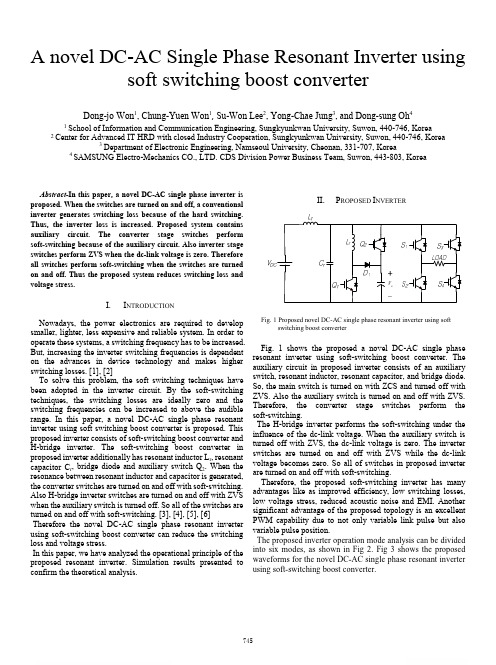
A novel DC-AC Single Phase Resonant Inverter usingsoft switching boost converterDong-jo Won1, Chung-Yuen Won1, Su-Won Lee2, Yong-Chae Jung3, and Dong-sung Oh41 School of Information and Communication Engineering, Sungkyunkwan University, Suwon, 440-746, Korea2 Center for Advanced IT HRD with closed Industry Cooperation, Sungkyunkwan University, Suwon, 440-746, Korea3Department of Electronic Engineering, Namseoul University, Cheonan, 331-707, Korea4 SAMSUNG Electro-Mechanics CO., LTD. CDS Division Power Business Team, Suwon, 443-803, KoreaAbstract-In this paper, a novel DC-AC single phase inverter is proposed. When the switches are turned on and off, a conventional inverter generates switching loss because of the hard switching. Thus, the inverter loss is increased. Proposed system contains auxiliary circuit. The converter stage switches perform soft-switching because of the auxiliary circuit. Also inverter stage switches perform ZVS when the dc-link voltage is zero. Therefore all switches perform soft-switching when the switches are turned on and off. Thus the proposed system reduces switching loss and voltage stress.I.I NTRODUCTIONNowadays, the power electronics are required to develop smaller, lighter, less expensive and reliable system. In order to operate these systems, a switching frequency has to be increased. But, increasing the inverter switching frequencies is dependent on the advances in device technology and makes higher switching losses. [1], [2]To solve this problem, the soft switching techniques have been adopted in the inverter circuit. By the soft-switching techniques, the switching losses are ideally zero and the switching frequencies can be increased to above the audible range. In this paper, a novel DC-AC single phase resonant inverter using soft switching boost converter is proposed. This proposed inverter consists of soft-switching boost converter and H-bridge inverter. The soft-switching boost converter in proposed inverter additionally has resonant inductor L r, resonant capacitor C r, bridge diode and auxiliary switch Q2. When the resonance between resonant inductor and capacitor is generated, the converter switches are turned on and off with soft-switching. Also H-bridge inverter switches are turned on and off with ZVS when the auxiliary switch is turned off. So all of the switches are turned on and off with soft-switching. [3], [4], [5], [6] Therefore the novel DC-AC single phase resonant inverter using soft-switching boost converter can reduce the switching loss and voltage stress.In this paper, we have analyzed the operational principle of the proposed resonant inverter. Simulation results presented to confirm the theoretical analysis.II.P ROPOSED I NVERTERFig. 1 Proposed novel DC-AC single phase resonant inverter using soft switching boost converterFig. 1 shows the proposed a novel DC-AC single phase resonant inverter using soft-switching boost converter. The auxiliary circuit in proposed inverter consists of an auxiliary switch, resonant inductor, resonant capacitor, and bridge diode. So, the main switch is turned on with ZCS and turned off with ZVS. Also the auxiliary switch is turned on and off with ZVS. Therefore, the converter stage switches perform the soft-switching.The H-bridge inverter performs the soft-switching under the influence of the dc-link voltage. When the auxiliary switch is turned off with ZVS, the dc-link voltage is zero. The inverter switches are turned on and off with ZVS while the dc-link voltage becomes zero. So all of switches in proposed inverter are turned on and off with soft-switching.Therefore, the proposed soft-switching inverter has many advantages like as improved efficiency, low switching losses, low voltage stress, reduced acoustic noise and EMI. Another significant advantage of the proposed topology is an excellent PWM capability due to not only variable link pulse but also variable pulse position.The proposed inverter operation mode analysis can be divided into six modes, as shown in Fig 2. Fig 3 shows the proposed waveforms for the novel DC-AC single phase resonant inverter using soft-switching boost converter.Fig. 2 Operation mode diagrams for the novel DC-AC single phase resonant inverter using soft-switching boost converterFig.3 Operation waveforms for the novel DC-AC single phase resonant inverter using soft-switching boost converterIII. E QUVALENT C IRCUIT A NALYSISMode 1 (t 0≤t<t 1): The resonant capacitor is discharged throughresonant path C r and L r . The resonant inductor current begins to increase linearly from zero. Therefore, the main switch is turned on with ZCS influenced by resonant inductor. The energy of the main inductor is delivered to the load through the switches (S 1, S 4).The next mode is started as soon as the resonant capacitor has fully discharged. In this mode, the main inductor current is given by(1)(2)Initial resonant inductor current and capacitor voltage given by(3)(4)The resonant period isThe resonant impedance is(6)The inductor current and resonant capacitor voltage in resonant period are given by,(7)(8)Mode 2 (t 1≤t<t 2): When the resonant capacitor is fully discharged to Mode1, the anti-parallel diodes in inverter switches constitute current path. At this time, the inverter stage is zero. When the inverter stage is in the zero voltage condition, the inverter switches are given to PWM signal (S 1, S 4). So, inverter switches are turned on and off with ZVS. This mode is maintained when the main switch is turned-off. The main inductor current is given by(9)The resonant inductor current and resonant capacitor voltage are given by(10)(11)Mode 3 (t 2≤t<t 3): When the switch is turned off with ZVS, the resonant inductor releases energy . Thus, the bridge diode is turned on. The dc-link capacitor is transferred to main inductor and resonant inductor energy through the bridge diode. The resonant capacitor starts to charge main inductor energy. At that time, the resonant inductor current and resonant capacitor voltage are given by(12)(13)(14)In this mode, the main inductor current is given by(15)(16)Mode 4 (t 3≤t<t 4): When the resonant inductor energy is fully released, the bridge diode is turned-off. This mode is maintained until the resonant capacitor voltage becomes 400[V]. The main inductor current flows continuously through the inverter switches (S 1, S 4). In this mode, resonant capacitor voltage is given by(17)(18)Resonant inductor current is given by(19)Mode 5 (t 4≤t<t 5): This mode is started when the resonant capacitor is fully charged. After that, the auxiliary switch is turned on with ZVS because the switch voltage is zero. When the main inductor current decreases linearly, the dc-link capacitor is charged from the main inductor energy. Because the main inductor current flows through the anti-parallel diode, the auxiliary switch voltage is zero voltage. When the auxiliary switch current path is changed, the next mode starts. In this mode, the main inductor current can be expressed as(20)1m in 1010()()cos ()sin ()o Lr L o o r r r Vi t I I I t t t t Z ωω=−+−+⋅−r Z =11010()()()in L L Vi t i t t t L =+−r t =1010()cos ()sin ()o cr o r o r r rVv t v t t I Z t t Z ωω=−−⋅⋅−11121()()()inL L V I t I t t t L=+−10min 0()()L Lr i t I i t ≅≅0()0Lr i t ≅0()cr out v t V ≅12()()()Lr Lr Lr i t i t i t ≅≅12()()0cr cr v t v t V≅≅()3232()()cos ()sin ()L o in Lr o o r r r I Ii t v v t t t t C Z ωω=+−−−−32()32()cos ()()sin ()cr o o r r in o L o r v t v v t t Z I I I t t ωω=−−+−−−11232()()()o inL L v vI t I t t t L−=−−12max()L I t I ≅3()0Lr i t ≅1433()()()L ocr C I I v t t t V t C−=−+34()()0Lr Lr i t i t ≅≅4()cr outv t V ≅11454()()()o inL L v v I t I t t t L−=−−Mode 6 (t 5≤t<t 6): In this mode, the auxiliary switch current path is changed because the dc-link capacitor starts to discharge. Therefore, the load is supplied the energy by the dc-link capacitor and main inductor. This mode maintains that the main inductor current equal to the resonant current. The main inductor current in this mode is expressed as(21)(22)(23)(24)After this mode ends, returning the mode 1.IV. S IMULATION R ESULTThis proposed resonant inverter is simulated to demonstrate the features and theoretical analysis. A 3kW prototype resonant inverter is built and simulated using the PSIM tool. The parameters used for simulations are as follow TABLE1.TABLE1. Simulation parametersFig. 4 shows simulation waveforms of converter stage in resonant DC-AC single phase inverter. During the resonance period between the resonant inductor and the resonant capacitor, the main switch and auxiliary switch are turned on and off with ZVS and ZCS.Fig.4 Simulation waveforms of converter stage in resonant DC-AC singlephase inverterFig.5 Principle operation waveforms of the proposed resonant inverterFig. 6 The waveforms of the voltage and the current of the main switchat turned-on and off with ZVSV dc 200[V] V dc-link 400[V] Main inductor 1000[μH] Resonant inductor 10[μH] Resonant capacitor 10[nF] DC-Link-Cap 1000[μF] Con. Switching Freq. 30[kHz] Inv. Switching Freq.15[kHz]11565()()()o inL L v v I t I t t t L−=−−56()()0Lr Lr i t i t ≅≅4()cr outv t V ≅16min ()L i t I ≅Fig. 7 The waveforms of the voltage and the current of the auxiliary switch at turned-on and off with ZVSFig. 8 The waveforms of the voltage and the current of the inverter switch at turned-on and off with ZVSFig. 5 presents principle operation waveforms of the proposed resonant inverter. When the switch current in inverter stage flows through the anti-parallel diode of inverter switch, the inverter switches maintain the freewheeling mode. Therefore, all inverter switches perform the soft-switching under the zero voltage condition.Fig.6 shows the main switch waveforms of the voltage and the current when the switch is turned and off with ZVS. Fig.7 shows the waveforms of the voltage and the current of the auxiliary switch at turned-on and off with ZVSDuring the resonant period, the bridge diode is turned on. At this time, dc-link capacitor is charged from resonant inductor energy when the current flows through the anti-parallel diode of auxiliary switch. Therefore, the auxiliary switch has zero-voltage condition. At this time, the switch is turned on with ZVS.Fig. 8 presents the waveforms of the voltage and the current of the inverter switch at turned-on and off with ZVS. All inverter switches have freewheeling mode, under the zero voltage condition. After this mode ends, returning the mode 1.V. C ONCLUSIONIn this paper, we proposed a novel DC-AC single phase resonant inverter using soft-switching boost converter. In this topology, all switches perform a soft switching by resonance between the resonant inductor and capacitor. So, the proposed topology can reduce the switching loss and voltage stress. The proposed inverter is analyzed through the operation mode, and its validity is proven through simulation.VI. A CKNOWLEDGMENTThis work is outcome of the fostering project of the Specialized Graduate School supported financial Ministry of Knowledge Economy (MKE).VII.R EFERENCES[1] D. M. Divan, G. Skibinski, “Zero switching loss inverters for highpower applications,” IEEE IAS Rec., pp. 627-634, 1987.[2]S.R. Park, S.H. Park, C.Y. Won, Y.C. Jung, "Low loss soft switchingboost converter", 2008 13th International Power Eletronics and Motion Control Conference (EPE-PEMC 2008) pp. 181 - 186. 2008[3]K. Wang, G. Hua, and F. C. Lee, “"Analysis, design and ZCS-PWMboost converters” in Proc. IEEJ Int. Power Electronics Conf., pp.1202-1207, 1995[4] G. Hua, X. Yang, Y. Jiang, and F.C. Lee, “Novel zero-current-transitionPWM converter”, IEEE Power Electronics Specialist Conf. Rec., pp.538~544, 1993.[5] H. Ohashi, ‘‘Power Electronics Inovation with Next GenerationAdvanced Power Devices’’, Proceeding of INTELEC'03, Oct.2003, Yokohama (Japan), pp.9-13[6] D. M. Divan and G. Skibinski, “Zero switching loss inverters for highpower applications,” IEEE IAS Rec., pp. 627-634, 1987.。
电子信息工程数据库管理中英文对照外文翻译文献

中英文对照外文翻译文献(文档含英文原文和中文翻译)译文:数据库管理数据库(有时拼成Database)也称为电子数据库,是指由计算机特别组织的用下快速查找和检索的任意的数据或信息集合。
数据库与其它数据处理操作协同工作,其结构要有助于数据的存储、检索、修改和删除。
数据库可存储在磁盘或磁带、光盘或某些辅助存储设备上。
一个数据库由一个文件或文件集合组成。
这些文件中的信息可分解成一个个记录,每个记录有一个或多个域。
域是数据库存储的基本单位,每个域一般含有由数据库描述的属于实体的一个方面或一个特性的信息。
用户使用键盘和各种排序命令,能够快速查找、重排、分组并在查找的许多记录中选择相应的域,建立特定集上的报表。
数据库记录和文件的组织必须确保能对信息进行检索。
早期的系统是顺序组织的(如:字母顺序、数字顺序或时间顺序);直接访问存储设备的研制成功使得通过索引随机访问数据成为可能。
用户检索数据库信息的主要方法是query(查询)。
通常情况下,用户提供一个字符串,计算机在数据库中寻找相应的字符序列,并且给出字符串在何处出现。
比如,用户必须能在任意给定时间快速处理内部数据。
而且,大型企业和其它组织倾向于建立许多独立的文件,其中包含相互关联的甚至重叠的数据,这些数据、处理活动经常需要和其它文件的数据相连。
为满足这些要求,开发邮各种不同类型的数据库管理系统,如:非结构化的数据库、层次型数据库、网络型数据库、关系型数据库、面向对象型数据库。
在非结构化的数据库中,按照实体的一个简单列表组织记录;很多个人计算机的简易数据库是非结构的。
层次型数据库按树型组织记录,每一层的记录分解成更小的属性集。
层次型数据库在不同层的记录集之间提供一个单一链接。
与此不同,网络型数据库在不同记录集之间提供多个链接,这是通过设置指向其它记录集的链或指针来实现的。
网络型数据库的速度及多样性使其在企业中得到广泛应用。
当文件或记录间的关系不能用链表达时,使用关系型数据库。
- 1、下载文档前请自行甄别文档内容的完整性,平台不提供额外的编辑、内容补充、找答案等附加服务。
- 2、"仅部分预览"的文档,不可在线预览部分如存在完整性等问题,可反馈申请退款(可完整预览的文档不适用该条件!)。
- 3、如文档侵犯您的权益,请联系客服反馈,我们会尽快为您处理(人工客服工作时间:9:00-18:30)。
Technology and Application of Fieldbus Control System -------- IntelligentEquipment & Measurement And Control System Based on DeviceNetPromoted by the new technological revolution that automation control technology is tending digitization and internet in the field of automation industry, Shanghai Aton Electric Co., Ltd. developed Intelligent Equipment & Measurement And Control System Based on DeviceNet as a high and new technology industrialization model project. It was a state hi-tech development project of 2000 and was approved by the State Committee of Technology. Shanghai Aton Electric Co., Ltd. constructed production line of intelligent controller of pump and valve, relying on Shanghai Electric (Group) Corporation; constructed measurement and control system FCS R&D center of intelligent controller of pump and valve and built up mass production R&D basis, cooperating with Shanghai Jiaotong University and Shanghai University; constructed FCS remote diagnosis and service center of intelligent controller of pump and valve; constructed FCS training center of intelligent controller of pump and valve; founded mass production R&D basis along with the Rockwell Laboratory of Shanghai Jiaotong University and CIMS Center.1 Summary(1)Fieldbus control system is a system applied to field of production and microcomputerized measurement control equipment to realize both-way multinode serial communications. It is also called low-level control network for open, digital and multiplespot communications.Application: Flow Control System of Manufacturing; Process Control System; Traffic Control & Management; Building Automation. Features: Fieldbus control system is low-level low-bandwidth digital communication and control network in industrial system as well as open system connecting microcomputerized appearance. Intelligent instrument and controller are equal to microcomputer. They make up network with Fieldbus control system as the links to complete digital communication and other tasks.(2)Difference between FCS and DCS,FCS is updated control system after DCS integrated with digital control system and distributing control system. It solves the problem that in traditional DCS, devices made by different manufacturers cannot be connected. They can't realize exchange and operation to organize an network system with wider range of information sharing. It conquers the defect that special closed system for network should be used for communication in DCS to realize various functions of integrated automation. It turns the distributing structure combining concentration with deconcentration in DCS into new-type full distributing structure. Itreleases the control function to the field thoroughly and makes it possible to realize basic control function by means of fieldbus equipment itself. FCS breaks the traditional structure form of control system. The traditional analog control system adopts one-to-one equipment tie-wire and puts up connections respectively according to control loop. FCS adopts intelligent field equipment to place the control module, all input/output modules that used to be in the control chamber of DCS into field equipment. Since field equipment has ability to communicate, the field measuring and transferring instruments can transfer signals to actuating mechanism such as valve directly. Its control function can be fulfilled directly on the spot independent of the computer or control meter in the control chamber, which realizes thorough decentralized control.FCS adopts digital signals to replace analog signals so that multiple signals (including multiple operating parameter values, device status and failure information) can be transferred on a pair of cables. Meanwhile, it can give power supply to several devices. No switched block for analog/digital or digital/analog is needed besides fieldbus.(3) C haracteristics of FCS• Open System;• Interoperability;• replace ability of devices made by different manufacturers.• Intelligentize and Autonomy;• Field equipment completing basic functions of automatic control.• Decentralized System Structure;• Field Adaptability;• Relatively Strong Interference Killing Feature and Safety• Intelligentized local equipment can save investment and quantity of hardware• Saving installation expenses and cables• Saving daily maintenance expenses• Enhancing accuracy and reliability of system• Enhancing initiativeness of system integration for users(4) Development Background and Trend of Fieldbus Control System, With the rapid development of computer and computer network, FCS has been rapidly developed as the interlinked communication network between the field intelligentdevices in the field of process automation, building and traffic etc. Because FCS meets the needs that industrial control system is developing in the way of decentralization, network and intellectualized, it has become the focus of global industrial automation and been universally concerned by the whole world. FCS has causedgreat revolutions on the aspects of system structure and function system for the current production of automation instrument, distributing control system and programmable controller. It is predicted that FCS will be the general trends in a very long time in the future fore sure.2 APPLICATION OF RELAYThe product reliability generally refers to the operating reliability. It is defined as: the ability of accomplishing the specified function under prescribed conditions and in prescribed time. It consists of intrinsic reliability and application reliability. The intrinsic reliability is determined by product designing and manufacturing technique, and the application reliability is concerned with the correct application of users and the services provided by the manufacturer before and after selling. When using relay, the user should pay attention to the following items.2.1 Coil applied voltageIt is best to choose the coil applicative voltage according to the rated voltage in design, or choose the voltage according to the temperature rising curve. Using any coil voltage that is less than the rated voltage will affect the operation of the relay. The coil operating voltage refers to the voltage that is applied between the coil terminals. The voltage value between the two terminals must be guaranteed, especially when using enlargement circuit to energize the coil. Whereas, it will also affect the relay characteristics if the applied voltage exceeds the highest rated voltage. Exorbitant voltage will bring exorbitant coil temperaturerising, especially in high temperature ambient. Exorbitant temperature rising will damage the insulating material and affect the working safety of relay. For magnetic latching relay, energizing (or return) pulse width should not less than 3 times of the operating (or return) time, otherwise, the relay would be left on the middle-position state. When using solid-state components to energize the coil, the components dielectric strength must be above 80V, and the leakage of current must be as little as possible to ensure the relay to release.Energizing power source: Under 110% of the rated current, the adjusting ratio of the power source is less than 10% (or the output impedance is less than 5% of the coil impedance), the wave voltage of the DC power source is less than 5%. The AC wave is sine wave; the waviness coefficient is between 0.95~1.25; wave distortion is within ±10%; the frequency change is within ±1Hz or ±1% of the specified frequency (choosing the bigger value). The output power should not less than coil power consumption.2.2 Transient suppressionAt the moment when the coil power is stopped, peak-inverse voltage that is more than 30 times ofthe coil rated voltage is produced on the coil, which is harmful to the electronic circuit. Generally, the peak-inverse voltage is suppressedby transient suppression (cutting-peak) diode or resistance to limit the peak-inverse voltage within 50V. But the diode in parallel connection will delay3~5 times of the release time. If the request of the release time is high, a suitable resistance in series can be putted with and at one end of the diode.The power supply to relays in parallel connection and series connection, When several relays in parallel connection are supplied, the relay that the peak-inverse voltage is higher will release power to the relays that the peak-inverse voltage is lower. The release time of the relay will delay. So the relays in parallel connection should be controlled separately to eliminate mutual influence.The relays with different coil resistance and power can'bt e used in series, otherwise, the relay that the coil current is higher in the series circuit can'otperate reliably. Only the relays of the same specification can be used in series, but the peak-inverse voltage will be increased and the peak-inverse voltage should be suppressed. Resistance in series can be used to bear the part voltage that exceeds the rated voltage of the coil according to the ratio of the divided voltage.2.2.1 Contact loadThe load applied to the contacts should be accordant to the rated load and characteristics of the contacts. A load that is not applied according to the rated value range will cause problem. The relay that is only suitable for DC load can used in ' t be AC occasions. The relay that can switch 10A load can ' t always reliably operate in low level load (less tha n 10m AX6A) or in dry circuit occasi ons. The relay that can switch single-phase AC power source isn 'atlways suitable to switch two single-phase AC loads that aren 't synchronous; the relay that is onlyiesdpteocisfwitch the load of AC 50Hz(or 60Hz)can't be used to switch AC load of 400Hz.2.2.2 Parallel and series connection of contactsThe contacts used in parallel connection can ' t increase the load current, becausethe operating times of several sets of contacts are absolutely different; that is to say, there is still only a set of contacts switching the increased load. This would damage or weld the contacts and make the contacts can ' t close or open. The parallel connectionof the contacts can decreasehte misplay of “ break ” . But the parallel connection of the contacts would increase the misplay of “ freezing ”. Because the misplay of “bre the main pattern of invalidation of contacts, the parallel connection can increase the reliability and can be used on the pivotal part of equipments. But the applied voltage should not exceed the highest operating voltage of the coil and should not less than 90% of the rated voltage, otherwise, the coil life and the applicative reliability would be damaged. The series connection of the contacts can increasethe load voltage. The amount of the contact sets is equal to the times that the load voltage can be increased.The series connection of contacts can decrease the misplay of “ freezing ”, but it w increase the misplay of “ break ”An. yway, when using redundant technology to increase the operating reliability of contacts, the characteristics and size and the failure mode of load must be considered.2.2.3 Switching speedThe switching speed should not exceed the reciprocal of 10 times of the sum of operating and release time (times/s), otherwise, the contacts can ' t switch on stead Magnetic latching should be used under the pulse width specified in the technique criterion, or the coil may be damaged.3 RVT DISTRIBUTING ELECTRICITY INTEGRATE TEST APPARATUSBasic functionMeasure asupervision:Three mutually electric voltage/electric current/ power factor with a great achievement/ power without a great achievement/electricity with a greatachiverment/electricity/homophonic-wave electric voltage/ homophonic-wave electric/ current Day electric voltage/ electric current biggest and minimum value/fire for the failure Electric voltage over top, the limit/ lack mutually of time homophonic-wave analyzes is up to 13 times.The data is stored for 2 months. The data communicateRS232/485 communicating connect,The way in communicating can adopt the spot communicating or the long range communicating. ,Possible to settle invoke orthe solid hour invokes, responding to the modification and long ranges control of the parameter. Without power compensationTaking physics measuresas the power factor without a great achievement,the power factor with a great achievement and the dull place without power compensation;Y+ the combination method of the △,Y+ the △ connects the line method,Y+ △ , Y, the △ connects the line method. Data managementAccording to WINDOW98 operation terrace, data in communication automatically reports born statement, curve and pillar form diagrams. Circulation of the protectionWhen the charged barbed wire net of mutually electric voltage over press, owe to press, and a super limit hour fast cut off in expiation of capacitor,When the charged barbed wire net lacks mutually or super limit in the preface of zero hour fast cut off in expiation of capacitor. screen manifestationChinese operation interface ,Adopt 128*64 the back light liquid crystal display.The solid hour shows the charged barbed wire net relevant parameter.view manifestation to place the parameter.现场总线控制系统的技术和应用随着新的科学技术革命的出现,在自动化工业领域中,自动控制技术的发展趋向于数字化和网络互联化。