压缩空气精密过滤器使用说明书
高效压缩空气过滤器Parker说明书

●Atmospheric Dirt ●Rust ●pipescale●Water Vapour ●Condensed Water ●Water Aerosols●Liquid Oil ●Oil Aerosols ●Oil Vapour●Micro – organismsCompressed air is an important source of energy in today’s modern production factories because it isflexible and reliable.1[[Contaminants are ever present in the atmosphere. The compressed air stream typically contains water, oil, dirt and micro-organisms which can contribute to product rejects, lost production time and increased maintenance expenses. For example, small traces of impurities can cause serious sheye blemishing in automotive nishing operations. Water left in air stream can freeze during exposure to cold temperatures, blocking ow or rupturing pipes. Residual compressor oil and water can form an acidic sludge and therefore, compressed air contaminants will eventually, lead to premature component wear, needing repairs or replacements.Most problems experienced by compressed air users derive from contamination that already in the compressed air system.There are typically 10 different contaminants. These are coming from four different sources:Before compressed air can be ef ciently used, these contaminants need to be removed orreduced to acceptable levels.Parker EcoPure Plus compressed air filter● Air flow from 0.6m 3/min to 40m 3/min ●Filter housings from 1/4” BSPP to 3” BSPP connections● Operate at pressures from 1 bar g to 16 bar g ● Technically advanced and proven technology ●Patented, unique element interface for high efficiency filter performance● Filter element performance guaranteed for 12 months * ●Air quality performance tested in accordance with ISO8573* - If used in accordance with manufacturer’s instructionsParker Hanni n, the global leader in motion and control technologies, carries a stable of strong known brands in the eld of compressed air treatment. Parker EcoPure Plus is our latest addition to this family and continues to offer a perfect high value solution to compressed air puri cation.The Parker EcoPure Plus range lter is designed by Parker’s highly trained team of lter experts with advanced and proven compressed air puri cation technology. It combines the key essential elements of Parker’s total ltration knowledge, pooled over decades of lter manufacturing experience to ensure clean compressed air with the minimum of cost.2Compressed air is expensive to produce and must be properly treated in order to limit maintenance costs,downtime and spoilage.[[3Filter PerformanceParker EcoPure Plus - Embodying the The Parker EcoPure Plus series of compressed air lters, inherits many characteristics of Parker’s compressed air ltration technology. Yes, this is Parker EcoPure Plus - an innovation in compressed air ltration, designed with reliability & ef ciency for you.Parker EcoPure Plus amasses decades of Parker's design experience in compressed air lters, drawing out the most perfect high value solution to compressed air puri cation. Most importantly, Parker EcoPure Plus delivers consistent high quality compressed air.In a comparative test of Parker EcoPure Plus lters against ve commonly available alternative lters, the blockage characteristics and the true differential pressure of each lter re ects its superior performance.Essence of Compressed Air Filters4Proven technology means Reliability & EfficiencyMaintaining air quality and energy efficiency through regular maintenanceParker EcoPure Plus lters carry air ow from the inside out; a long understood and proven method. Liquid contaminants are captured in the lter matrix and collect together into larger and larger droplets through collisions with the media. These droplets eventually coalesce on the outside of the lter tube where they collect and are drained away by gravity.The inner element surface acts as a pre- lter to remove large contaminants while the internal pores are trap and to remove aerosols and solids from the air stream. The larger outside pores also allow a smooth air stream to pass freely through the media, minimizing pressure drop.Another important relationship is the gap between the lter element outside diameter and the lter bowl's inner diameter. The spacing between these two surfaces are sized so that air velocity is minimized, thus reducing the possibility of oil or water vapor carryover.It has long been the practice to change lter elements based upon the pressure drop measured across the lter as this directly contributes to increased operational costs. However, one must remember the reason for installing the lter in the rst place, i.e. to achieve high quality compressed air.Filter elements must always be replaced in accordance with the manufacturers instructions to ensure the delivered air quality is never compromised.Parker EcoPure Plus- Feature The zero-loss drain (standard forltration grades GP & HE) features an auto-cleaning protection screen for highest reliability. Simply press the drain to verify its correct operation.As the clean air exits the element, outlet air stabilizers direct the air out of the lter housing with the minimum of turbulence andpressure loss. These also ensure the element is located correctly within the lter bowl.The differential pressureindicator gives a visualindication on the current state of the lter element.(option)To maintain your guaranteed air quality, lter elements must be replaced every year with genuine Parker parts. Throughout its life, the lter element is constantly under bombardment from oily, acidic condensate and high velocity dirt particles, which needs to be removed and retained to protect your compressed air system.5Surface ProtectionAll sizes of housings are built to the highest quality standards, featuring our unique surface protectiontreatment, applied to both the inside and the outside of the lter housing. Thanks to the attention of quality surface treatment, Parker EcoPure Plus can withstand even the toughest industrial conditions and comes with a 5 year guarantee on the lter housings.Filtration MediaModern coalescing lters use a graded porosity lter medium with ne glass bers in the interior and larger bers on both the inside and outside surfaces. Parker EcoPure Plus elements have 8 to 10μm pores on the inner surface, reducing to 0.5 μm pores in the interior of the element, and widening to 40 to 80μm pores on the outer surface.Coalescing ElementsThis coalescing element is made with Parker’s special UNI-CAST construction. Composing an epoxy saturated, borosilicate glass micro- ber media, this media is used in applications requiring the removal of liquid and particulate contamination. The outer synthetic fabric layer allows swift removal of coalesced liquids.6minimum clearanceCompressed Air Standards and ApplicationsFrom aeration in pharmaceutical and chemical processes to pneumatic power systems, the possibilities for applications are endless. Parker has some suggested air cleanliness standards that may fit your needs.International Standard ISO8573-1 has become the industry standard method for specifying compressed air cleanliness. The following diagrams describe various systems in terms of their corresponding ISO classification.The applications are based upon the test result of GP-060-FX, HE-060-FX and AC-060-MX.Product SelectionStated flows are for operation at 7 bar g (100 psi g) with reference to 20°C, 1 bar a, 0% relative water vapour pressure.For flows at other pressures apply the correction factors shown.Correction FactorsFilter Coding ExamplesTo correctly select a filter model, the flow rate of the filter must be adjusted for the minimum operating pressure of the system 1. Obtain the minimum operating pressure and maximum compressed air flow rate at the inlet of the filter.2. Select the correction factor for minimum operating pressure from the CFP table (always round down e.g. for 5.3 bar, use 5 bar correction factor)3. Calculate the minimum filtration capacity Minimum Filtration Capacity = Compressed Air Flow Rate x CFP4. Using the minimum filtration capacity, select a filter model from the flow rate tables above (filter selected must have a flow rate equal to or greater than the minimum filtration capacity)Filtration GradesGrade GP filters are used as pre-filters for Grade HE to remove gross amounts ofparticle, water and oil aerosols.Grade GPGrade HEGrade ACAdsorption Element(removal of vapor and odor)9(Precede with Grade GP filter) Grade HE filters are used when “total removal of particle, water and oil aerosols” is required. Because of its overall performancecharacteristics, this grade is most often recommended.(Precede with Grade HE filter) Grade AC are used to remove oil vapor and odor. It is used to remove smell or taste ofcompressor lube oil, as well as trace amounts of oil vapour in the compressed air stream.Weights and DimensionsAccessories1. Tested per ISO 8573.2.2. Oil vapor removal efficiency is given for AC media.Differential Pressure Gauge Float Drain Manual Drain10Europe domnick hunter IndustrialDukesway, Team Valley Trading Estate Gateshead, Tyne & Wear England NE11 0PZT +44 (0) 191 402 9000, F +44 (0) 191 482 Compressed Air TreatmentParker Gas SeparationsOude Kerkstraat 4P O Box 2584870 AG Etten-Leur, NetherlandsT +31 76 508 5300, F +31 76 508 5333Hiross ZanderPadova Business UnitStrada Zona Industriale 435020 S. Angelo di Piove Padova, Italy T +39 049 9712 111, F +39 049 9701 Hiross ZanderEssen Business UnitZander Aufberaitungstechnik GmbH Im Teelbruch 118D-45219 Essen, GermanyT +49 2054 9340, F +49 2054 934164www.zander.deRacorShaw Cross Business Park Churwel Vale Dewsbury,WF12 7RD England T +44 (0) 1924 487000, F +44 (0) 1924 /rfdeRacor Research & DevelopmentParker Hannifin GmbH & Co KG Inselstrasse 3-570327 Stuttgart Germany T +49 (0) 711 7071 290-0, F +49 (0) 711 7071 /racorHydraulic FilterStieltjesweg 8, 6827 BV P.O. Box 5008 6802 EA Arnhem, HollandT +31 26 3760376, F +31 26 /hfdeUrjala OperationSalmentie 26031700 Urjala as FinlandT +358 20 753 2500, F +358 20 753 /hfdeCondition Monitoring CenterBrunel Way Thetford,Norfolk IP 24 1HP EnglandT +44 1842 763299, F +44 1842 /hfdedomnick hunter ProcessDurham Road, Birtley Co. Durham,DH3 2SF EnglandT +44 (0) 191 410 5121, F +44 (0) 191 410 Engine Filtration & Water PurificationHydraulic FiltrationProcess FiltrationNorth AmericaW o r l d w i d e M a n u f a c t u r i n g L o c a t i o n sParker Hannifin Filtration Products and Systems (Shanghai) Co.,LtdNo.2 Workshop,786 Wangqiao Road,Jinqiao Processing Southem Zone,Shanghai, ChinaTel: +(86)21 5838 3030Fax:+(86)21 5838 2428Parker Hannifin Corporation Filtration GroupGlobal Headquarters 6035 Parkland Boulevard Cleveland, OH 44124-4141T 216 896 3000, F 216 896 Engine Filtration &Water PurificationRacor - Village Marine Tec.2000 West 135th Street Gardena, CA 90249T 310 516 9911, F 310 538 Hydraulic FiltrationHydraulic Filter16810 Fulton County Road #2Metamora, OH 43540-9714T 419 644 4311, F 419 644 /hydraulicfilterProcess FiltrationProcess Advanced Filtration2340, Eastman Avenue Oxnard, CA 93030T 805 604 3400, F 805 604 /processfiltrationFiltration & Separation/Balston242 Neck RoadHaverhill, MA 01835-0723T 978 858 0505, F 978 858 /balston Filtration & Separation/Finite500 Glaspie Street, PO. Box 599Oxford, MI 48371-5132T 248 628 6400, F 248 628 /finitefilterPurification, Dehydration and Filtration Division4087 Walden Avenue Lancaster, NY 14086T 716 685 4040, F 716 685 /pdfSales Office5900-B Northwoods Parkway Charlotte, NC 28269T 704 921 9303, F 704 921 Racor3400 Finch Road, PO Box 3208Modesto, CA 95353T 209 521 7860, F 209 529 /racorChina280 YunQiao RoadJinQiao Export Processing Zone Shanghai 101206 ChinaT +86 21 5031 2525, F +86 21 5834 /chinaIndiaPlot EL 26, MIDC, TTC Industrial Area Mahape, Navi Mumbai 400 709 India T +91 22 5613 7081, 82, 83, 84, 85F +91 22 2768 6618 /indiaJapan626, Totsuka-cho, Totsuka-ku Yokohama-shi, 244-0003 JapanT +81 45 870 1522, F +81 45 864 /japanKorea1-C Block, Industrial Complex of Jangan,615-1, Geumui-Ri Jangan-Myeon,Hwaseong-City Gyeonggi-Do, Korea T +82 31 359 0771, F +82 31 359 /koreaSingapore11, Fourth Chin Bee Road Singapore 619 702T +65 6887 6300, F +65 6261 /singaporeThailand1023 3rd Floor, TPS Building Pattanakam Road, Suanluang,Bangkok 10250 ThailandT +66 2717 8140, F +66 2717 /thailandLatin AmericaAfricaParker Comercio Ltda.Filtration DivisionEstrada Municipal Joel de Paula 900 Eugenio de Melo,Sao Jose dos Campos CEP 12225-390 SP BrazilT +55 12 4009 3500, F +55 12 4009 /brPan American Division-Miami7400 NW 19th Street, Suite A Miami, FL 33128T 305 470 8800, F 305 470 /panamParker Hannifin Africa Pty LtdParker Place, 10 Berne Avenue,Aeroport Kempton Park,1620 South AfricaT +27 11 9610700, F +27 11 /euAsia PacificAustralia9 Carrington Road, Castle Hill NSW 2154, AustraliaT +61 2 9634 777, F +61 2 9899 /australiaCompressed Air TreatmentFC-2-54A 12/03。
空压机精密过滤器说明书

空压机精密过滤器说明书目录1.概述2.过滤器的作用3.过滤器的结构4.过滤器的工作示意图5.过滤器的安装6.过滤器的操作步骤7.日常管理及注意事项8.常见问题及处理方法1.概述过滤器是工业空气处理过程中主要的净化设备之一。
空气压缩系统中的空气通常来至普通空气,经过空压机压缩后除含有一定数量的水分外还含有其他细小颗粒、悬浮物,油份等残留杂质。
这些杂质的存在会对相关设备及产品产生危害。
2.过滤器的作用当压缩空气通过过滤器时,由于过滤器中的过滤介质(碳素纤维、活性碳等)的接触絮凝作用、吸附和截留作用使得杂质被吸附、截留。
通过过滤器的过滤,可进一步降低空气的浊度等。
3.过滤器的结构3.1过滤器的分类过滤器直径可从Ф300mm—Ф3000mm,依据直径大小可分为大型过滤器和小型过滤器。
一般直径小于1000mm的称为小型过滤器,直径大于1000mm的称为大型过滤器。
3.2过滤器的结构3.2.1壳体过滤器的壳体有钢衬胶,或不锈钢,或玻璃钢或塑料等。
3.2.2滤料根据要求的不同和使用范围的不同,过滤器的滤料有石碳素纤维、活性碳等。
3.2.3操作系统有管道、阀门、自动排水器等。
4.过滤器的工作示意图表1压缩空气不纯物用途过滤器(尘埃)水份油份脱臭① 3um - - - 建筑清洁用土木机械金属制品制钢压力成型路面工程② 3um - 99.9% - 气力工具一般工厂控制阀涂装③ 0.01um 压力露点 0.1ppm - 仪器静电涂装精密工业精密零件干燥电子工业④ 0.01um 2℃ 0.1ppm 99.5% 食品工业、输出医药工业搅拌、干燥包装呼吸用⑤ 0.01um 压力露点2℃ 0.1ppm 99.5% 超干燥呼吸用电脑室高压电绝缘集中管理计装用粉体储藏、输送化学分析装置4.1级别4.1.1过滤器级别选用参见上图。
表2 过滤器级别等级过滤精度残油量P 3μ≤3 PPMU 1μ≤0.5 PPMH 0.01μ≤0.01 PPMC 活性碳吸著式4.1.2过滤器的配套一般人可能只根据所需要的空气质量选择相应处理精度的过滤器,而不考虑过滤器的配套使用。
Finite BA-Series 双阶段压缩空气过滤器说明书
2
How it works
Port 1
Air In
4.65”
Port 2
Clean Air Out
Compressed air enters port #1 of the housing and is directed down
by means of a non-bypassing separation device. The second stage’s
BA-Series filters may also be used in applications requiring compressed air to be free of odor or taste bearing hydrocarbons. Food/beverage applications would be typical where compressed air comes in contact with the product. The BA-Series can also be used as a prefilter for critical needs such as zero air generators, membrane filters and many others!
Note: This product does not
element into the bowl where it is
remove toxic gases from the air
removed either manually, or by an
stream. A carbon monoxide moni-
Replacement elements are supplied in convenient repair kits which include one coalescing element, two activated carbon adsorber elements, and replacement seals. Two adsorber elements are supplied because the stage one coalescer will routinely outlive the extremely sensitive second stage adsorber element.
汉吉森高性能压缩空气过滤器说明书
New modular housings for flows
synonymous with cost-efficient treatment of
compressed air. 50 years of successful work New matrix blended fiber media
through 1325 m³/h
3 Colour coded elements for easy
identification
3 Slide indicator (up to HF-20)
3 Economical - changes colour when filter
element requires replacement
3 Inlet screen at condensate drain for addi-
rust and scale, compressor lubricants,
condensed water droplets and acidic Withstands temperatures to 66°C.
condensates, oil and hydrocarbon vapors. The-
A typical compressed air system is contaminated Chemically resistant end caps bound to
with abrasive, solid particles such as dust, dirt,
meulated adhesive
saving running costs.
their production procedure.
Parker OIL-X 压缩空气过滤器手册说明书

FILTRO PER ARIACOMPRESSA OIL-XFiltri per aria compressaMANUALE UTENTE: 17 118 6004 08/19 Rev. AGuida alla manutenzione: 171186001Guida all'installazione e configurazione: 171186002Manuale utente FiltrazioneP010 - P055 (WS, A0, AA, ACS)0405091116131819222123201217071014– Installazione del sistema OIL-X– Raccomandazioni per l'installazione– Codifica dei modelli– Portate del separatore d'acqua– Portate del filtro – Dati tecnici– Portate del filtro– Dichiarazione di conformità– Accessori/Ricambi– Parker nel mondo– Pesi e dimensioni del filtro– Depressurizzazione del sistema – Rimozione del bicchiere del filtro– Rimozione di elementi del bicchiere del filtro – Sostituzione dello scarico automatico– Etichetta di promemoria manutenzione – Procedura di avviamento del sistema– Intervalli di manutenzione– I nserimento di elementi di ricambio nel bicchiere del filtro– S ostituzione della guarnizione dell'o-ring della testa del filtro– Reinstallazione del bicchiere nella testa del filtro– Procedura di avviamento – Configurazione di esercizio– P esi e dimensioni del separatore d'acqua– Video: GuidaRACCOMANDAZIONI PER L'INSTALLAZIONERACCOMANDAZIONI PER L'INSTALLAZIONESi raccomanda che l'aria compressa venga trattata prima dell'ingresso nel sistema di distribuzione e nei punti di utilizzo/applicazioni critici.L'installazione di essiccatori per aria compressa in un sistema precedentemente umidificato potrebbe generare ulteriore sporco nei filtri sul punto di utilizzo durante l'essiccazione del sistema di distribuzione.In questo periodo potrebbe essere necessario cambiare gli elementi filtranti più frequentemente.Nelle installazioni in cui sono utilizzati compressori senza olio e sono ancora presenti aerosol d'acqua e particolato, devono essere ancora utilizzati gradi generici e ad alta efficienza.Un filtro per uso generico deve sempre essere installato per proteggere il filtro ad alta efficienza da aerosol di liquidi dispersi e particolato solido. Installare un'apparecchiatura di depurazione alla temperatura più bassa oltre il punto di congelamento, preferibilmente a valle di postraffreddatori e serbatoi d'aria.Il punto di utilizzo dell'apparecchiatura di depurazione deve essere installato il più vicino possibile all'applicazione.L'apparecchiatura di depurazione non deve essere installata a valle di valvole ad apertura rapida e deve essere protetta da eventuali flussi inversi o urti.Spurgare tutte le tubazioni in ingresso nell'apparecchiatura di depurazione prima dell'installazione, dopo l'installazione e prima della connessione all'applicazione finale.Se le linee di bypass sono installate attorno all'apparecchiatura di depurazione, assicurarsi che venga fornita una filtrazione adeguata alla linea, per evitare la contaminazione del sistema a valle.Installare le linee di scarico dai filtri a coalescenza direttamente in un separatore di condensa. Se non è possibile collegare le linee di scarico direttamente a un separatore, sfiatare le linee in un manifold di condensa (dotato di sfiato a un'estremità) e quindi in un unico ingresso di un separatore di condensa.Incaricare un'azienda preposta per lo smaltimento dei liquidi raccolti dall'apparecchiatura di filtrazione.I liquidi raccolti devono essere trattati e smaltiti responsabilmente.PROCEDURA DI AVVIAMENTOPrima di pressurizzare il filtro, assicurarsi che la testa e il bicchiere siano installati in modo appropriato e che il blocco sia allineato correttamente. Aprire lentamente la valvola di ingresso (01) per pressurizzare gradualmente il filtro e attendere 1 minuto (02) prima di aprire lentamente la valvola di uscita (03) per ripressurizzare le tubazioni a valle.Nota: non aprire le valvole di ingresso o uscita rapidamente né sottoporre l'unità a una pressione differenziale eccessiva, in quanto possono verificarsi danni.0 bar7 bar0103WSAAAO 1 minuto02WSAAAOMANUTENZIONE DEL PRODOTTOINTERVALLI DI MANUTENZIONEPer prestazioni ottimali del filtro, gli elementi filtranti a coalescenza e anti-particolato asciutto OIL-X Grado AO e OIL-X Grado AA devono essere sostituiti ogni 12 mesi (8736 ore) insieme allo scarico automatico con galleggiante.A differenza degli elementi filtranti a coalescenza e anti-particolato asciutto, che vengono sostituiti annualmente per garantire laqualità dell'aria compressa, la durata dell'elemento filtrante ad adsorbimento e della cartuccia può dipendere da vari fattori e richiedere sostituzioni più frequenti. I fattori che influiscono sulla durata dei filtri ad adsorbimento sono:Concentrazione dei vapori d'olioMaggiore è la concentrazione di vapore d'olio in ingresso, più rapidamente si esaurisce la capacità del materiale di adsorbimento, con conseguente riduzione della durata dell'elemento filtrante ad adsorbimento e della cartuccia.Grandi quantità di olioI filtri ad adsorbimento sono progettati solo per ridurre vapori di olio e odori, non olio liquido o sospensioni di olio. Un prefiltraggio con scarsa manutenzione o inesistente (filtri a coalescenza) causa il rapido esaurimento della capacità del filtro con conseguente rapida riduzione della durata dell'elemento filtrante ad adsorbimento e della cartuccia.TemperaturaIl contenuto di vapori di olio aumenta in modo esponenziale rispetto alla temperatura di ingresso, riducendo la durata dell'elemento filtrante ad adsorbimento e la cartuccia. Inoltre, nella misura in cui aumenta la temperatura, la capacità di adsorbimento del materiale adsorbente diminuisce, riducendo ulteriormente la durata dell'elemento filtrante ad adsorbimento e della cartuccia.Umidità relativa e punto di rugiadaL'aria umida riduce la capacità di adsorbimento del materiale adsorbente e la durata dell'elemento filtrante ad adsorbimento e della cartuccia. In teoria, i filtri ad adsorbimento in linea devono sempre essere installati a valle dell'essiccatore per aria compressa per prolungare la durata degli elementi filtranti ad adsorbimento e della cartuccia.Cambio dell'olio del compressoreQuando si cambia l'olio del compressore, il nuovo lubrificante brucia "componenti leggeri", aumentando il contenuto di vapore di olio per ore o settimane dopo il cambio. Questo incremento del contenuto di vapore di olio viene adsorbito dall'elemento filtrante o dalla cartuccia, riducendone la durata.Filtri ad adsorbimento OIL-X Grado ACSL'elemento OIL-X Grado ACS offre prestazioni ottimali a una temperatura di ingresso nominale di 21 °C, con punto di rugiada in pressione a -40 °C e concentrazione massima di vapore di olio di ingresso di 0,018 mg/m3. In queste condizioni il filtro OIL-X Grado ACS avrà una durata di 650 ore. L'uso del filtro OIL-X Grado ACS a temperature di ingresso/concentrazioni di vapore di olio di ingresso superiori o a monte di un essiccatore ad adsorbimento o frigorifero riduce la durata del filtro ad adsorbimento. Sostituire l'elemento filtrante a carbone se si rilevano vapori, odori o sapori. I filtri OIL-X Grado ACS sono raccomandati per applicazioni al punto di utilizzo solo dove la sostituzione degli elementi con più frequenza è accettabile.Filtr iA differenza dei filtri ad adsorbimento in linea (OIL-X Grado ACS), i filtri ad adsorbimento OIL-X Grado OVR sono dimensionati e selezionati non solo per fornire aria di qualità costante ma anche per garantire una durata della cartuccia di 12 mesi. La durata di 12 mesi (6000 ore per modelli OVR 100 ~ OVR 250 e 8736 ore per modelli OVR 300 ~ OVR 550) della cartuccia dipende dal dimensionamentodei seguenti parametri di ingresso: temperatura di ingresso massima/tipo di compressore, pressione di ingresso minima, posizione nel sistema (a monte o a valle dell'essiccatore) e contenuto di vapori di olio. Il filtri ad adsorbimento OIL-X Grado OVR sono progettati sia per l'intero impianto (sala compressori) che per applicazioni al punto di utilizzo.Chiudere lentamente le valvole di ingresso (01) e di uscita (02) e depressurizzare il filtro (03) utilizzando lo scarico.Svitare il bicchiere del filtro (01 e 02) e rimuovere gli elementi utilizzati (03).Nota: per rimuovere il bicchiere dei filtri 050 e 055 potrebbe essere necessaria una chiave a nastro.Attenzione0 bar/0 psi010203Attenzione0 bar/0 psiGuanti di protezioneSmaltire in modo sicuro0102Rimuovere l'elemento del bicchiere del filtro.Svitare lo scarico automatico (01) e smaltirlo (02). Installare il nuovo scarico (03) e serrarlo (04).2,5 N/mSmaltire in modo sicuro0104030203Inserire il nuovo elemento nel bicchiere del filtroaccertandosi che i capicorda siano posizionati correttamente nelle scanalature.Sostituire l'o-ring posto nella testa del filtro con il nuovo o-ring fornito.Reinstallare il bicchiere e la testa del filtro accertandosi che le filettature siano completamente inserite (01) e i blocchi siano allineati (02).Nota: per garantire che il bicchiere sia completamente inserito nella testa, è necessaria una rotazione di 360° fino all'arresto filettato per il bicchiere 010-030, di 720° per il bicchiere 035-045 e di 540° per il bicchiere 050-055.Accertasi di lubrificare l'o-ring e le filettature con un tipo di vaselina priva di acidi adeguato.0201Fino a 720°Non aprire le valvole diingresso o uscita rapidamentené sottoporre l'unità a unapressione differenzialeeccessiva, in quanto possonoverificarsi danni.Attaccare l'etichetta con la data di sostituzione dell'elemento al bicchiere del filtro e annotarvi sopra la data della sostituzione successiva, ad esempio dopo 12 mesi.Aprire lentamente la valvola di ingresso (01) per pressurizzare gradualmente il filtro e attendere 1 minuto (02) prima di aprire lentamente la valvola di uscita (03) per ripressurizzare le tubazioni a valle.Non utilizzaresolventi o alcol perpulire le etichette inquanto ciò potrebbecausare danni.0 bar/0 psi7 bar/100 psi011 minuto0203PROBLEMI? GUARDATE LA GUIDAGuarda la guida sul sito Web Parker Hannifin CONTENUTO DEL VIDEOInstallazione del sistema OIL-XProcedura di avviamentoDepressurizzazione del sistemaRimozione del bicchiere del filtroRimozione di elementi dal bicchiere del filtroSostituzione dello scarico automaticoInserimento di elementi di ricambio nel bicchiere del filtroSostituzione della guarnizione dell'o-ring della testa del filtroReinserimento del bicchiere nella testa del filtroEtichetta di promemoria manutenzioneProcedura di avviamento del sistemaSPECIFICHE TECNICHEESEMPIO DI CODIFICA DEI MODELLISCELTA DEL PRODOTTOI valori di portata indicati si riferiscono al funzionamento a 7 bar g (100 psi g), con valori di riferimento a 20o C, 1 bar (a), 0% di pressione relativa al vapore acqueo.Per valori di portata in presenza di altri livelli di pressione applicare i fattori correttivi indicati.MODELLO A = 1/4"B = 3/8"C = 1/2"D = 3/4"E = 1"G = 1 1/2"H = 2"I = 2 1/2"J = 3"G = BSPP N = NPTF = Galleggiante M = ManualeX = Nessuno I = Monitor criticitàWS AO AA ACS030PCodice a 3 cifre come mostrato di seguitoPORTATE DEL SEPARATORE D'ACQUACFP – Fattore di correzione della pressione minima di ingresso (separatori d'acqua)MODELLODIMENSIONIATTACCOL/SM 3/MINM 3/HCFMP010A P020D P045I P010C P035G P025E P055JP010B P025D P050I P015C P040H P030G [ ][ ][ ][ ][ ][ ][ ][ ][ ][ ][ ][ ][ ][ ][ ][ ][ ][ ][ ][ ][ ][ ][ ][ ][ ][ ][ ][ ][ ][ ][ ][ ][ ][ ][ ][ ][ ][ ][ ]¼¾2 ½½1 ½1½13⅜¾2 ½½2104035010350110800101108004.2 2-235EPDM 1100,62,421,00,621,06,648,00,66,648,02,421,06,636144126036126039628803639628801441260396218574221742233169521233169585742233161514131211109876543212322182031891741601451311161008773584429150,680,710,730,760,790,820,850,890,941,001,141,331,592,002,634,00DATI TECNICIMODELLOMODELLI DI FILTROMIN. DI ESERCIZIO PRESSIONE MAX DI ESERCIZIO PRESSIONE MIN. RACCOMANDATA TEMP . DI ESERCIZIO MAX RACCOMANDATA TEMP . DI ESERCIZIOBAR GBAR GOCOCPSI GPSI GOFOFNota: i filtri di grado AO/AA/WS per l'uso fino a 16 bar g (232 psi g) sono forniti con scarico galleggiante [F] di serie.Per pressioni da 16 a 20 bar g (da 232 a 290 psi g), è necessario utilizzare uno scarico manuale [M].I filtri di grado ACS sono forniti con scarico manuale [M] di serie.P010P010P010P010P010P010055055055055055055[ ][ ][ ][ ][ ][ ][ ][ ][ ][ ][ ][ ][ ][ ][ ][ ][ ][ ][ ][ ][ ][ ][ ][ ]F M M FFM F M M FFM [ ][ ][ ][ ][ ][ ][ ][ ][ ][ ][ ][ ]11111116202016162015151515151523229029023223229022222235353535353580100100808050176212212176176122––––––P030G P050I P040H P055JP035G P055I P045I 1 ½2 ½231 ½2 ½2 ½1104302206201606203306,625,813,237,39,637,319,823391146613143391314699P030P050P040P055P035P055P0453961548792223257622321188PORTATE DEL FILTROCFP – Fattore di correzione della pressione minima di ingresso (filtri a coalescenza e anti-particolato asciutto)MODELLODIMENSIONI ATTACCOL/SM 3/MINKIT ELEMENTI DI RICAMBIOM 3/HCFMN.P010A P020C P010C P025D P010B P020D P015C P025E ¼½½¾⅜¾½110301060103020600,61,80,63,60,61,81,23,6216421127216442127P010P020P010P025P010P020P015P025[Grado][Grado][Grado][Grado][Grado][Grado][Grado][Grado][Grado][Grado][Grado][Grado][Grado][Grado][Grado]111111*********3610836216361087221616201519141813171211109876543212322902182772032631892481741601451311161008773584429150,680,710,730,760,790,820,850,890,941,001,141,331,592,002,634,00[ ][ ][ ][ ][ ][ ][ ][ ][ ][ ][ ][ ][ ][ ][ ][ ][ ][ ][ ][ ][ ][ ][ ][ ][ ][ ][ ][ ][ ][ ][ ][ ][ ][ ][ ][ ][ ][ ][ ][ ][ ][ ][ ][ ][ ]PESI EDIMENSIONI DEL SEPARATORE D'ACQUAPESI E DIMENSIONI DEL SEPARATORE D'ACQUAMODELLOTUBO MISURAALTEZZA (H)(A)LARGHEZZA (L)(B)PROFONDITÀ (P)(C)PESOMMMMMMMMMMMMKGINSINSINSINSINSINSLB¼13½1 ½¾2 ½⅜1 ½½2¾2 ½180277516180440238440180277238440277516154232444154383202383154232202383232444761201927616489164761208916412019250701205010050100507050100701206509021836515784157650902841570902183383840383838383838383838400,802,6410,830,786,691,356,280,792,541,086,462,6410,807,0910,9120,317,0917,329,3717,327,0910,919,3717,3210,9120,316,069,1317,486,0615,087,9515,086,069,137,9515,089,1317,482,994,727,562,996,463,56,462,994,723,56,464,727,561,972,764,721,973,941,973,941,972,761,973,942,764,722,564,537,202,566,183,316,182,564,533,316,184,537,201,51,51,571,51,51,51,51,51,51,51,51,51,571,765,8323,891,7214,742,9813,851,755,612,3914,235,8323,81WSP010A WSP025E WSP055JWSP010C WSP035G WSP020D WSP045I WSP010B WSP030G WSP015C WSP040H WSP025D WSP050I Nota: i separatori d'acqua non presentano alcun indicatore DP , utilizzare le dimensioni H + d per l'altezza complessiva.Diametro del tubo (dimensioni attacco)bicchiere rimozione GiocoW ACHBDPESI EDIMENSIONI DEL FILTROPESI E DIMENSIONI DEL FILTROMODELLOTUBO MISURAALTEZZA (H)(A)LARGHEZZA (L)(B)PROFONDITÀ (P)(C)PESOMMMMMMMMMMMMKGINSINSINSINSINSINSLB¼¾2 ½3½1 ½½2⅜1½1 ½¾2 ½2 ½1802776548441803672385321802772384402385328441542325827721543222024751542322023832024757727612019219276120891647612089164891641925070120120507050100507050100501001206509021831836509028415765090284157841571833232686832323868323232683268680,842,1410,3015,300,823,041,177,300,842,691,166,901,447,1015,97,0910,9125,7533,237,0914,459,3720,947,0910,919,3717,3210,9120,9433,236,069,1322,9130,396,0612,687,9518,76,069,137,9515,077,9518,730,392,994,727,567,562,994,723,56,462,994,723,56,463,56,467,561,972,764,724,721,972,761,973,941,972,761,973,941,973,944,722,564,537,207,202,564,533,316,182,564,533,316,183,316,187,201,51,51,571,571,51,51,51,51,51,51,51,51,51,51,571,864,7122,7133,731,816,702,5816,091,865,922,5515,213,1915,6535,05P010A P025D P050I P055JP010C P030G P020C P040H P010B P025E P015C P035G P020D P045I P055I W ACHBDDiametro del tubo (dimensioni attacco)Gioco rimozione bicchiereCMODELLI DI FILTRON. CAT.INDICE010010010025 – 030025 – 030025 – 030015 – 020015 – 020015 – 020035 – 045035 – 045035 – 045050 – 055050 – 055035 – 055010 – 055TRK1-2MBK1-1MBK1-2TRK3-2MBK3-1MBK3-2TRK2-2MBK2-1MBK2-2TRK4-2MBK4-1MBK4-2TRK5-2MBK5-1ZD90GL EM1ACCESSORI/RICAMBI (KIT DI MANUTENZIONE)PARKER NEL MONDOAE – EAU, DubaiTel.: +971 4 8127100********************AR – ARGENTINA, Buenos AiresTel.: +54 3327 44 4129AT – AUSTRIA, Wiener NeustadtTel.: +43 (0)2622 23501-0*************************AT – EUROPA ORIENTALE,Wiener NeustadtTel.: +43 (0) 2622 23501 900****************************AU – AUSTRALIA, Castle HillTel.: +61 (0)2-9634 7777AZ – AZERBAIGIAN, BakuTel.: +994 50 2233 458****************************BE/LU – BELGIO, NivellesTel.: +32 (0) 67 280 900*************************BR – BRASILE, Cachoeirinha RSTel.: +55 51 3470 9144BY – BIELORUSSIA, MINSKTel.: +375 17 209 9399*************************CA – CANADA, Milton, OntarioTel.: +1 905 693 3000CH – SVIZZERA, EtoyTel.: +41 (0)21 821 87 00*****************************CL – CILE, SantiagoTel.: +56 2 623 1216CN – CINA, ShanghaiTel.: +86 21 2899 5000CZ – REPUBBLICA CECA, KlecanyTel.: +420 284 083 111*******************************DE – GERMANIA, KaarstTel.: +49 (0) 2131 4016 0*************************DK – DANIMARCA, BallerupTel.: +45 43 56 0400*************************ES – SPAGNA, MadridTel.: +34 902 330 001***********************FI – FINLANDIA, VantaaTel.: +358 (0) 20 753 2500*************************FR – FRANCIA, Contamine s/Arve Tel.: +33 (0)4 50 25 80 25************************GR – GRECIA, Atene Tel.: +30 210 933 6450************************HK – Hong Kong Tel.: +852 2428 8008HU – UNGHERIA, Budapest Tel.: +36 1 220 4155*************************IE – IRLANDA, Dublino Tel.: +353 (0) 1 466 6370*************************IN – INDIA, Mumbai Tel.: +91 22 6513 7081-85IT – ITALIA, Corsico (MI)Tel.: +39 02 45 19 21***********************JP – GIAPPONE, Tokyo Tel.: +81 (0) 3 6408 3901KR – COREA DEL SUD, Seul Tel.: +82 2 559 0400KZ – KAZAKISTAN, Almaty Tel.: +7 7272 505 800****************************LV – LETTONIA, Riga Tel.: +371 6 745 2601************************MX – MESSICO, Apodaca Tel.: +52 81 8156 6000MY – MALESIA, Shah Alam Tel.: +60 3 7849 0800NL – Paesi Bassi,Oldenzaal Tel.: +31 (0) 541 585 000********************NO – NORVEGIA, Asker Tel.: +47 66 75 34 00************************NZ – NUOVA ZELANDA, Mt Wellington Tel.: +64 9 574 1744PL – POLONIA, Varsavia Tel.: +48 (0)22 573 24 00************************PT – PORTOGALLO, Leca da Palmeira Tel.: +351 22 999 7360**************************RO – ROMANIA, Bucarest Tel.: +40 21 252 1382*************************RU – RUSSIA, Mosca Tel.: +7 495 645-2156************************SE – SVEZIA, Spånga Tel.: +46 (0)8 59 79 50 00************************SG – Singapore Tel.: +65 6887 6300SK – SLOVACCHIA, Banská Bystrica Tel.: +421 484 162 252**************************SL – SLOVENIA, Novo Mesto Tel.: +386 7 337 6650**************************TH – TAILANDIA, Bangkok Tel.: +662 717 8140TR – TURCHIA, Istanbul Tel.: +90 216 4997081************************TW – TAIWAN, Taipei Tel.: +886 2 2298 8987UA – UCRAINA, Kiev Tel.: +380 44 494 2731*************************UK – REGNO UNITO,Warwick Tel.: +44 (0) 1926 317 878********************US – USA, Cleveland Tel.: +1 216 896 3000VE – VENEZUELA, Caracas Tel.: +58 212 238 5422ZA – SUD AFRICA,Kempton Park Tel.: +27 (0) 11 961 0700*****************************22Filtro per aria compressa OIL-X - Manuale utente. ©2019.Centro informazioni prodotti per l'Europa Numero verde: 00 800 27 27 5374(da AT, BE, CH, CZ, DE, EE, ES, FI, FR, IE, IL, IS, IT, LU, MT, NL, NO, PT, SE, SK, UK)GARANZIA DI UN ANNO SULLAQUALITÀ DELL'ARIALa garanzia della qualità dell'aria ha durata di 1 anno e si rinnova a ogni sostituzione annuale degli elementi filtranti.Le sostituzioni annuali degli elementi filtranti garantiscono:• Prestazioni ottimali costanti• Qualità dell'aria sempre conforme agli standard internazionali• Protezione delle apparecchiature a valle, del personale e dei processi• Costi operativi ridotti• Maggiore produttività e redditività• TranquillitàPARKER HANNIFIN MANUFACTURING LIMITEDGas Separation and Filtration Division EMEADukesway, Team Valley Trading EstGateshead, Tyne and WearInghilterra NE11 0PZTel.: +44 (0) 191 402 9000Fax: +44 (0) 191 482 6296/gsfe© Parker Hannifin Corporation. Tutti i diritti riservati.。
压缩空气与气体过滤器产品有限公司的过滤器功能指南说明书
Compressed Air & Gas Filtration ProductsFinite Filtration Capabilities GuideBasics of Coalescing FiltrationThis fi lter housing cutawaydepicts the coalescing process. Air enters the housing and fl ows through the fi lter media passing from the inside element surface to the outside.Coalesced liquid collects in the housing where it is drained, and clean air exits the housing through the outlet port.CleanAir OutDirty Air InFor example, trace amounts of submicronic oil can cause serious fi sh eye blemishing in automotive fi nishing operations. Water left in air lines can freeze during exposure to cold, blocking fl ow or rupturing pipes. Compressor lubricant not captured in a coalescing fi lter willeventually collect in pneumatic components, causing premature component repair or replacement. Environmental concerns will be raised if oily, compressed air is continually discharged into Q.What is coalescing fi ltration?A. A steady state process whereby aerosols are caused to agglomerate (come together) into even larger droplets as they pass through the fi lter elements’ fi ber matrix, eventually becoming large enough to be gravitationallydrained away.Q.Why fi lter compressed air?Submicronic contaminants in compressed air systems can:• Plug orifi ces of sensitive pneumatic instrumentation • Wear out seals• Erode system components• Reduce the absorptive capacity of desiccant air/gas dehydrators• Foul heat transfer surfaces• Reduce air tool e ciency resulting in:• Product rejects• Lost production time• Increased maintenance costsA.the atmosphere through a pneumatic mu er.• Compressed air/gas fi lters • Par-Fit™ conversion elements• Instrumentation and gas sampling fi lters • CNG/Alternative fuel fi lters • Steam and vacuum exhaust fi lters • Air dryers•Drains, gauges, and other accessoriesFinite Filters & AccessoriesFinite o ers a full line of low to high pressure gauges, brackets, and drains.Superior Design and ConstructionOur UNI-CAST glass microfi ber fi lters, formed with a proprietary vacuum process, combine surface (edge) fi ltration with enhanced depth fi ltration. UNI-CAST pore construction traps largerpore-clogging particles on the surface while allowing access to the element’s internal fi ber matrix for coalescing and submicron particulate removal. The result is lower pressure drop and less frequent change-outs, saving you time and money.What Separates Finite Filters from the Competition?In addition to our broad selection of quality fi lters, we o ervalue-added services including:Value-Added Services• Custom branding • Kitting• Local Parker stores• Compressed air analysis • In-house training•Competitor interchange elementsOEM CapabilitiesFinite fi lter experts are ready to work with you. Our team will tailor a confi guration to meet your special need from the wide variety of fi lter media available. With LEAN manufacturing, special product capabilities allow enhanced performance to your product andcontinued support of aftermarket replacement elements.Finite coalescing, particulate, absorption, and water separating elements assure that clean compressed air is always available for unique industrial applications. These media types are available across Finite product families to ensure your application functions at maximum performance.Compressed Air & Gas Treatment Filtration ProductsApplications• Spray painting • Powder coating • Blow molding • Printing • Packaging• Pneumatic conveying • Air gauging •Air bearingsFilters-Regulators-Lubricators• Two- and three-unit combos• Metal and polycarbonate bowls available • Pressures to 250 PSIG•Connections from 1/8” to 1½” NPT• Coalescing, particulate, and adsorption • Pressures to 185 PSIG • Temperatures up to 450º F• Connections from 3” NPT to 16” fl ange • Flows up to 37,000 SCFM • Custom designs available • Available with a variety of fi ltration media •Captures .01 - 100 micronASME Coded VesselsPar-Fit™ Conversion Elements• Coalescing, particulate and adsorption elements • O er UNI-CAST Finite advantage •Over 2500 interchanges availableWater Separators• Remove bulk water from your application • Connections from 1/4” to 3” NPT • Pressures to 230 PSIG• Flows from 25-17,000 SCFM •Temperatures up to 175º F• For point-of-use and OEM applications• Pressure dewpoints down to -40° F • Connections from 1/4” to 1” NPT • Ideal for intermittent fl ows• Di erential pressure gauges• Float, solenoid, and zero-air-loss drains • Mounting brackets and adapter kitsFDD Desiccant DryersAccessories• Compressed air hollow fi ber membrane dryers• Pressure dewpoints down to -40° F • Connections from 1/4” to 1/2” NPT • Flows up to 40 SCFMMembrane Dryers40° FNPT • Coalescing, particulate, and adsorption elements • Pressures to 500 PSIG • Temperatures up to 450º F • .01 -100 micron• Connections from 1/4” to 3” NPT , BSPF , & BSPT • Flows from 10 to 1600 SCFM •Available with a variety of fi ltration mediaH-SeriesFinite’s H-Series compressed air fi lters are the most widely used fi lter. Our standard grade 6 element captures 99.97% of particulate,oil, and water contamination.• 1/4” - 3” NPT • 15-1,300 SCFM • 290 PSIG• Temperatures up to 212º F •.01 - 100 micronHX Series FiltersSN3L & SN4L Stainless Steel Filters for Harsh Environments• 3/4” - 1” NPT • 80-170 SCFM• Pressures up to 250 PSIG • Temperatures up to 450º F •.01 - 100 micronely usAlternative Fuel & High Pressure Filtration ProductsApplications• CNG refueling stations • CNG on-board vehicle• Hydrogen refueling stations • Hydrogen on-board vehicle • Natural gas processing • Landfi ll methane fi ltration • O -shore oil drilling• Process/chemical plants •High pressure (SCUBA) breathing air• Hydraulic test systems • Plastic bottle blow moldingHigh pressures encountered in CNG (Compressed Natural Gas) and other alternative fuel systems add another dimension to fi lter performance and magnify the problems of preventing contamination. Excessive amounts of liquid aerosols and solid particulate contamination lead to poor component performance, wear, and unscheduled maintenance. Finite o ers a variety of high-pressure compressed air and gas fi lters for every stage of compression.From the gas well to the dispenser, Parker offers a full line of compressed natural gas fi lters.• Coalescing, particulate, and adsorption elements • Pressures to 500 PSIG • Temperatures up to 450º F • .01 -100 micron• Connections from 1/4” to 3” NPT , BSPF , & BSPT• Flows from 10 to 1600 SCFM • Available with a variety of fi ltration mediaH-SeriesFinite’s H-Series compressed air fi lters are the most widely used fi lter. Our standard grade 6 element captures 99.97% ofparticulate, oil, and water contamination.• Pressures to 800 PSIG• Connections from 1/4” to 2” NPT , BSPT & BSPF • Use with specialty gases • Variety of fi lter elements available • Flows from 6-590 SCFM • Temperatures up to 175ºF •Captures .01-100 micronMedium Pressure Filters, M-Series• CNG, alternative fuel and breathing air fi lters • Pressures to 5000 PSIG• Ductile iron and nodular cast iron• Coalescing, particulate, and adsorption fi lter elements available • 1/4”-2” NPT• Flows from 15-26, 230 SCFM • Temperatures up to 350ºF •Captures from .01-100 micronHigh Pressure Filters, J-SeriesHigh Flow Stainless Steel Filters, SNS8• 2” NPT• Pressures to 500 PSIG • T emperatures up to 175ºF •Variety of fi lter elementsavailable• Used in the most demanding environments • Pressures from 250 PSIG• Connections from 3/4” to 1” NPT • Flows up to 170 SCFMSN3L & SN4L Stainless Steel Filters for Harsh EnvironmentsHigh Pressure Stainless Steel Filters, SJ-Series• Compatible with high pressure specialty gases • Pressures to 6000 PSIG • Variety of fi lter elements available • Temperatures up to 350ºF • Captures .01 to 3 micronStainless Steel Filters• Safely drain condensate under pressure• Pressures to 6000 PSIG• Directly connect to J-Series and SJ-Series• Horizontal or vertical mountingHigh Pressure Drains• Coalescing, particulate and adsorption• Pressures to 185 PSIG • Connections from 3” NPT to 16” fl ange• Flows up to 37,000 SCFM • Available with a variety of fi ltration mediaASME Coded VesselsDisposable LiquidPropane Filters (LPGD-200)• 1/2” SAE• Flows from 1-1.5 and 4-10 GPM • Pressures up to 500 PSIG • Temperatures up to 250ºF •Captures 1-5 micronReplaceable LiquidPropane Filters (LPGR-200)• 1/2” NPT , SAE-8• Flows from 1-1.5 and 4-10 GPM• Pressures up to 800 PSIG • Temperatures up to 250ºF •Captures 1-5 micronOn-Board CNG FiltrationFFC-110• 1/4”-1/2” NPT • 6-590 SCFM• Pressures up to 800 PSIG •Temperatures up to 221º FFFC-112• 1/4” NPT• 12-576 SCFM• Pressures up to 3,600 PSIG •Temperatures up to 221º FFFC-113• 1/2” NPT• 34-1,922 SCFM• Pressures up to 3,600 PSIG •Temperatures up to 221º FCompressed Natural Gas, or CNG, is a leading alternative to traditional fuel for the automotive industry. CNG is used in passenger vehicles, pickup trucks, in transit and on school buses. It can be less expensive than gasoline, and is more environmentally friendly – it reduces the amount of carbon monoxide, carbon dioxide and hydrocarbon vehicle exhaust emissions. Natural gas is gathered from a pipeline and travels to a connecting compressor station. The gas is elevated to pressures ranging from 2000 PSIG up to 5000 PSIG and the resultant CNG is stored in large tanks. The CNG then makes its way to a gas dispenser where it is ready for use in natural gas vehicles.Contaminants can enter into the gas at any stage of this processing. Filters are critical at each stage to ensure clean gas as a fi nal prod-uct. Contamination that collects during handling, water that condenses in tanks and compressors that leak oil into the fuel stream are all prob-lems that could shorten the life of expensive equipment, create unnecessary downtime and increase maintenance costs.From pipeline to engine, Finite fi lters provide the critical fi ltration required for most alternative fuel systems.Low Flow Instrumentation Filters• Stainless steel, aluminum, and plastic housings• Clear bowls available• Connections from 1/8” to 2” NPT •Pressures to 5000 PSIGAnalytical Gas Sampling Filters• Gas analyzer protection • Pressures to 6000 PSIG• Stainless steel and aluminum housings • Variety of fi lter elements available • 1/8”-1/4” NPT• Flows from 2-45 SCFM (aluminum)Flows from 2-437 SCFM (stainless steel)• Pressures up to 1000 PSIG (aluminum)Pressures up to 5000 PSIG (stainless steel)• Temperatures up to 225ºF (aluminum)Temperatures up to 400ºF (stainless steel)•Captures .01-100 micronSpecialty Filter Elements - Par-Fit Series• Coalescing, particulate and adsorption fi lter media • Filter media ranging from stainless steel mesh to PTFE membrane• Compatible with a variety of gases, including refrigerantGas Sampling & Specialty FiltrationApplications•Food, beverage sanitization, and cooking • Dairy and meat packing sanitation • Air conveying of dry food products • Compressed air bakery mixing • Pharmaceutical manufacturing • Hospital sterilization • Respirator air purifi cation • Laboratory gas sampling •Industrial breathing airFinite fi lters eliminate overall contamination, taste di erences, and odors in food products and facilitate sterilization in hospitals and pharmaceutical processing facilities. Finite fi lters provide absolute rated fi ltration for contaminants as small as 0.01µm to assure contamina-tion-free processing in semiconductor, pharmaceutical, food and beverage applications.Protect your products and your workingenvironmentParker offers kitting for systemapplications. This assembly is used to provide breathable air for fi ve people.Disposable Gas Sampling Filters• Pressures up to 100 PSIG • Connections from 1/8” - 1/4”• Flows from .8-5.3 SCFM • Temperatures up to 125ºF •Captures from .01-44 micronBRO_FNT-Finite Capabilities_092022Parker Hannifi n CorporationIndustrial Gas Filtration and Generation Division 242 Neck RoadHaverhill, MA 01835Phone 800 343 Aerospace Filtration Division Greensboro, North Carolina 336 668 4444Bioscience & Water Filtration Division Bioscience Filtration Oxnard, California 877 784 2234Water Puri cation Carson, California 310 608 5600Engine MobileAftermarket Division Kearney, Nebraska 308 234 1951Engine Mobile Original Equipment Division Modesto, California 209 521 7860HVAC Filtration Division Jeffersonville, Indiana Industrial Gas Filtration & Generation Division Lancaster, NY 800 343 4048Industrial Process Filtration Division Mineral Wells, T exas 940 325 2575Bioscience Engineering Filtration Division EMEA Birtley, United Kingdom +44 (0) 191 410 5121Engine Mobile Filtration Division EMEADewsbury, United Kingdom +44 (0) 1924 487 037Gas Separation &Filtration Division EMEA T eam Valley, United Kingdom +44 (0) 191 402 9000Gas Turbine Filtration Division Australia Filtration Division Castle Hill, Australia +61 2 9634 7777China Filtration Division Shanghai, China +86 21 2067 2067India Filtration Division Chennai, India +91 22 4391 0700Korea Filtration Division Hwaseon City, Korea +82 31 359 0852Latin America Filtration Division Sao Paulo, Brazil +55 12 4009 3500Parker Filtration Group。
Parker Zander 迷你过滤器系列:压缩空气、气体和疲劳过滤器说明书

Compressed air,gas and vacuum filtersCompressed air filters are now recognised as being an integral part of any system.Few,if any, compressed air systems can ope-rate successfully without high effi-ciency filters.Production and pro-cess standards demand the finest quality air and components are now manufactured to such tight tolerances that no contamination is permitted.We are one of the leaders in the purification of compressed air,gas and vacuum filters.Their product development is lead by strongpartnerships with compressed airand gas users to ensure the bestavailable product for increasinglydemanding applications.Dust,dirt and oil mist filtration iscommon enough today.ParkerZander emphasises,not only thefiltration efficiency but,important-ly,links this to energy costs interms of pressure differential,pro-duct consistency and reliability.Micro-filter-compressed air,gas and vacuum filtersBoth types of housings are built to the highest quality standards and have a double surface protection. The aluminium housings are alu-chromed and epoxy powder coated,the steel housings are intensivly cle-aned,polyester primed and acrylicpainted.Thanks to the attention of qualitysurface treatment,Parker Zanderoffers a10year guarantee on thefilter housings.This gives confiden-ce to the user!G-Housings with threaded connection from G1/4to G3 -High grade aluminium casting -Alu-chromed in and outside to prevent corrosion-Powder coated to ensure top quality finish F-Flanged housingsDN80to DN300-Welded mild steel vessels -Sand blasted,cleaned and de-greased-Polyester primed in and outside -Acrylic paint outsideMicro-filters in two housing formats:Filter HousingsUntreated and Alu-chromed filter bowlsafter a salt spray test acc.toDIN50021SS>250hoursAll Micro-filter housings are two piece.This means that,no matter what the size is,one person can change the filter ele-ments.This saves having to employ a helper!The F flanged filter housings,which can weigh up to a ton,have a hinged lower cover,which one person can open and close,when it is time to change the elements.Parker ZANDER Micro-filterMicro-filter Housing ConstructionOther types of housingMicro-filter Tie RodThe tie rod fixing of the element to the housing ensures that the ele-ment sits in the housing without any possibility of movement and therefore leakage between the dirty and clean side.The lower end cap of the element is firmly secured to the tie rod.This elimi-nates any possibility of the end cap flying off under severe shock conditions.Equally,the tie rod makes the ele-ment easier to change.There is no risk of the element end cap corro-ding.This does occur when alumini-um threads on the element corrode into the housing.This means anexpensive new housing instead of a simple ele-ment replacement.A small difference with large cost savings!Parker Zander element secured with tie rodAnother methodMicro-filter Modular ConceptThe user can install simply and economically Micro-filters inmodular units up to the ing a filter combination kit,the installer can link together up to three filters in a set.This lowers the conse-quential pressure drop.These filter combinationscan be easily wall mounted with brackets.Parker Zander filter housings combinati-onsOther types of housing linked with pipe or nip-ples3piece hous-ing with retain-ing ring2piece housingG FWDH KW G1/4-G3 DN80-DN300Standard combination (up to G13size only)Combination kits wall brackets G2StandardScrewedplugs Pressure diffe-rential gaugemanual drainFilter with G1/2thread connection,plug in(Standard on V–XP4)Filter with G1thread connection,oil removal"no-loss”condensate drain ED3000range.G2connection with activated carbon filter,Wall bracketsExamplesEOPK2K3Electronic filtermonitor DeltatronicOil indicatorElectronic level sensing drain Electronic level sensing drain Parker Zander filters use machine pleated elements,which form the heart of the filter.These pictures -higher dirt holding capacity -longer service life -lower operating costsTechnical DataC a p a c i t y *1n o m i n a lC o n n e c t i o nM a x .p r e s s u r eD i m e n s i o n sW e i g h tF i l t e r e l e m e n t*2calculated for constant velocity and 20°CExample 1:If you have a flow of 1300m 3/h (1bar a and 20˚C)–)at a minimum working pressure of 10bar e,what size filter do you require?Answer:Flow ÷f =1300m 3/h ÷1.38=940m 3/h =>G14size Example 2:What is the nominal flow through a G14filter with a minimum working pressure of 10bar e?Answer:Flow:·f =940m 3/h ·1.38=1300m 3/h (1bar a and 20˚C)Micro-filterParker Zander mm mm mm mm Anzahl/Type m 3/h G/DN bar A B C D kg TypeG 230G 1/4166016514600,61/1030G 350G 1/4168721521751,01/1050G 570G 3/8168721521901,01/1070G 7100G 1/21687285211601,21/1140G 9180G 3/416130325431353,81/2010G 11300G 116130425432354,51/2020G 12470G 11/216130525433355,01/2030G 13700G 11/216130725435256,41/2050G 14940G 216164825485209,61/3050G 171450G 21616410754877012,31/3075G 181940G 21/21625010507460024,61/5060G 192400G 31625012007475027,01/5075F 171850DN 8016380128017553052,01/3075F 192920DN 8016440132020553079,01/5075F 203700DN 100165001440230550106,02/3075F 305550DN 100165001440230550106,53/3075F 407400DN 150166401590280550148,04/3075F 6011100DN 150167901650300550208,06/3075F 8014800DN 200167901730340550230,08/3075F 10018500DN 200168401780360550368,010/3075F 12022200DN 250169401940420600450,012/3075F 16029600DN 250169401940420600460,016/3075F 20037000DN 300169401970450600520,020/3075*1Calculated at 1bar a and 20˚C at 7barg working pressureFilter Element Performance Tables Pre-filter element V–0.02bar (dry)–0.07bar (saturated)–99.99%(3µ)General Purpose Filter ZP –0.03bar (dry)–0.10bar (saturated)–99.9999%(1µ)–≤0.5mg/m 3(1bar a and 20˚C)Oil Removal Filter XP –0.06bar (dry)–0.15bar (saturated)–99.99999%(0.01µ)–≤0.01mg/m 3(1bar a and 20˚C)Super Fine Filter XP4–0.12bar (dry)–0.28bar (saturated)–≥99.99999%(0.01µ)–≤0.001mg/m 3(1bar a and 20˚C)Activated Carbon Filter A –0.03bar -≤0.003mg/m 3(1bar a and 20˚C)with an inlet concentration of ≤0.01mg/m 3Activated Carbon Cartridge KTA –Depending on size 0.15-0.4bar –bar (Oil Removal as A grade)Conversion factor f for other operating pressures*2Operating pressure bar e12345678910111213141516f=0.250.380.500.630.750.881.001.131.251.381.501.631.751.882.002.13DimensionsPre-filter,General purpose filter and Superfine filter V,ZP,ZX,XP4Standard format with automatic condensate drainGrades VD (E),ZPD(E),XPD(E)and XP4(E)Complete with automatic drain and differential pressure gauge (E with volt-free contact)Activated carbon filter A &KTAStandard format with manual drainActivated carbon filter AOP &KTAOPComplete with manual drain and oil indicatorDimensions with electronic condensate drainsLS rangeLC rangeG2-G13G14-G17/F17G18-F20F40-F120F160-F200G2-G13G14-G19/F19F20-F40F60-F200ED 3002ED 3004ED 3007ED 3030ED 3100ED2010ED2010ED2010ED2020MKMKMKMKMKMKMKMKMKM14-G38G12-G12G12-G12G10-G12G10-G12M14-G12G12-G12G10-G12G10-G34G10-G12Parker Hannifin CorporationZANDER Aufbereitungstechnik GmbH Im Teelbruch 118D-45219EssenTel:+49(0)20549341Fax:+49(0)2054934164www.zander.deYour local authorized Parker distributor。
压缩空气过滤器系列说明说明书

CompressedAir FiltrationCompressed Air Filtration Filters | Coalescers | Absorbers | Elements | Mist EliminatorsIn any compressed air net distribution it is a must to install one or more filters. As a result, an improved air quality is achieved, which benefits your complete compressed Using only a single filter could result in saturation of the reduced air quality or end upprematurely replacing your elements.TECHNOLOGY YOU CAN TRUSTA V A I LAB I L I T Y S E R VI C E AB IL I T Y R E L I A B I L I T YP A R T N ER SH IPS I MP L I C I T YUser BenefitsBoost quality and productivity • Purify the compressed air by eliminating oil/dust contaminants • Higher final product quality• Increase your overall productivity Save costs• Prolong the life span of your operation process (machine/equipment...)• Reduce potential downtime• Annual service intervals to ensure optimal operations Easy operation and installation Compatible with any compressor technology• Can be installed quickly and into an existing network• Optional pressure drop device (indicator/gauge) to advise on the cartridge replacement• Cartridge replacement done in no time• No electrical supply neededRisks You AvoidImpurities in the compressed air can cause:• Damage to the distribution lines, increasing the leakage risk • A considerable increase in maintenance costs• A reduction in the efficiency and life span of the pneumatic devices • Deterioration of the final product quality• Limitations to the reliability of the production process and all its components• Decrease of the overall profitabilityQuincy Filters Keep Your Air Distribution Network In Optimal Shape!2Important GuidelinesWhen selecting purification equipment for your compressed air system, these are some useful guidelines to consider:1. Depending on the application, each point of use in the system may require a different compressed air quality.2. Ensure that the purification equipment which is being chosen will provide the required air purity in accordance with the classi-fications from the ISO 8573-1:2010 table.3. When comparing filters to one another, make sure they have been tested in accordance with the standards of ISO 8573 and ISO 12500 series.4. Whenever you compare different filtration solutions, it is crucial to keep in mind that the filter performance is highly dependent on the inlet conditions.5. When taking into account the operational cost of oil coalescence filters, only compare the initial saturated wet pressure loss. The reason for this is that dry pressure loss is not representative forperformance in a normally wet compressed air system.36. For dust filters on the other hand, one can expect the pressure drop to rise over time. A low starting pressure drop does not mean it will remain as such throughout the filter element’s lifetime.7. Consider the total cost of ownership for purification equipment (purchase, operational and maintenance costs).Your local sales representative can help you to select the optimal purifcation equipment for your compressed air system.Compressed Air According to ISO 8573-1:2010Depending on the customer’s application, a certain air purity is required. These purity requirements have been categorized in air purity classes. The purity classes are defined in the ISO 8573-1 standard, edition 2010.This table defines 7 purity classes ranging from 0 up to 6 following the rule: the lowr the class, the higher the air quality.Model Grades 1800-10,500A Solution for Every Air QualityReference condition: pressure 7 bar (102 PSI). Maximum operating temperature of 122°F, only for QAF series.Minimum operating temperature of -4°F4Model Grades 6-1500Filter Range OverviewThe quality of air required throughout a typical compressed airsystem varies. Offering an extensive filter range, Quincy Compressor can always match your precise requirements, ensuring that all types of contamination are avoided and costs are reduced to an absolute minimum.QMF Filter RangeMicronic coalescing filters for general purposeprotection, removing solid particles, liquid water and oil aerosol.Total Mass Efficiency: 99 %QPF Filter RangeParticulate filters for dust protection. Removes solid particles, dust, liquid and oil aerosol.Count Efficiency: 99.8% at MPPS (MPPS = 0.1 micron)QCF Filter RangeHigh-efficiency coalescing filters, removing solid particles, liquid water and oil aerosol.Total Mass Efficiency: 99.9 %QAF Filter RangeActivated carbon filter for removal of oil vapour and hydrocarbon odors.1000 Hour Lifetime* Inlet oil concentration = 40 mg/m3** MPPS = Most Penetrating Particle Size of 0.01 µm5High Temperatures1 Micron Dust Filters, 450°F, 150 PSIG• Designed specifically for Heat Reactivated Desiccant Air Dryers • Nomex outer layer is provided for high-temperature operation • Push-to-fit design used on threaded filters for easy filter element replacement•Multiwrap element construction provides optimum performanceAluminum Housing Threaded NPT Connctions 15 to 650 CFM, Series HTDT• Features a high-temperature dust filter with heavy-duty bowl • Ribbed bowl facilitates removal when changing elements NOTE: Alloy filters shipped loose will have a special high-temperature black powder coat paint.ModelsHTDT 15 & 30Models HTDT 65–650Specifications & Engineering Datasponding to the working pressure.6Mechanical Moisture Separators6 to 1500 CFM, 232 PSIG, Series QWSQuincy Mechanical Moisture Separators are designed to removebulk liquids and large volumes of water. They are typically installeddownstream of after coolers, air receivers, refrigerated air dryers andat strategic points of use throughout the compressed air distributionsystem. The design employs an internal spinner to create a centrifugalaction that effectively removes large quantities of water.• Aluminum housings (1⁄4” to 3 NPT) to prevent corrosion• Low pressure drop: < 1 PSIG• CRN approvedSpecifications & Engineering Data7Stainless Steel FiltersCoalescer — AbsorberQuincy’s line of 316 grade Stainless Steel filters for pressure requirements of 750 PSIG through 5000 PSIG feature:• Three pressure ranges (750 PSIG, 1,500 PSIG, 5,000 PSIG)• Heavy-duty, Stainless Steel tie rod design for 1500 PSIG and 5000 PSIG750 PSIG/250°F 60 to 2000 SCFM (1/2” to 2” NPT)• SSCT standard coalescer • SPCT polishing coalescer • SACT activated carbon1500 PSIG/250°F 65 to 2050 SCFM (1/2” to 2” NPT)• ESCT standard coalescer • EPCT polishing coalescer • EACT activated carbon5000 PSIG/250°F 28 to 775 SCFM (1/2” to 11/2” NPT)• VSCT standard coalescer • VPCT polishing coalescer • VACT activated carbonHigh-PressureAluminum FiltersCoalescer — AbsorberQuincy’s aluminum alloy, 750 PSIG high-pressure filter lineup offers an economic alternative to the high cost of stainless steel. There are two levels of coalescing and an activated carbon absorber. Ideally suited for the PET bottle blowing industry, the coalescers remove various levels of liquid aerosols and the activated carbon absorber removes vapor and odors.• High-temperature capacity (250°F.)• Multiwrap element construction for optimum performance and long life• Synthetic lubricant and mineral oil compatibility• Large sump and quiet zone to prevent re-entrainment • Push-to-fit design for easy filter element replacement• Modular design allows for easy installation of multiple filters and saves energy750 PSIG/250°F 150 to 3000 SCFM (1/2” to 2” NPT)• HSCT standard coalescer • HPCT polishing coalescer • HACT activated carbon750 PSIG - Specifications & Engineering Data8corresponding to the working pressure.corresponding to the working pressure.9High-Pressure1500 & 5000 PSIG - Specifications & Engineering Data10corresponding to the working pressure.corresponding to the working pressure.11Models E_T 65-2050V_T 28-775Models H_T 94 & 147Models S_T 60–2000ModelsH_T 265–1882Unique Double Element Design1,500 cfm through 15,000 cfm models utilize a space-saving double element design (see Figure 2). Using a double nesting technique, the Quincy Mist Eliminator offers high efficiency separation in a low profile package. By nesting an element inside an element, total surface area is greater than conventional single element designs. Due to reduced overall height, the Quincy Mist Eliminator can be installed in locations where conventional single element designs cannot. For example, a 10,000 cfm Quincy Mist Eliminator low profile design is only 118 inches tall. Compare this to other single element designs that are 210 inches tall. That’s a reduction of over 7 feet in overall height! Imagine the savings in time and convenience when you change the element or service the unit.All Quincy Mist Eliminator tanks are ASME coded and stamped. Standard equipment includes a calibrated differential pressure gauge and enamel paint. No Loss Demand Drains are optional. Pressure relief valves are not included but may be required by local codes.Mist EliminatorHigh Efficiency Heavy-Duty Coalescing FilterLong Life and Low Pressure DropThe Quincy Mist Eliminator is a heavy-duty coalescing type filter engineered to efficiently remove oil, particulate, and water from compressed air. By using a combination of impaction, interception and Brownian Movement, the Quincy Mist Eliminator achieves100% efficiency in removing particles 3 micron and larger, 99.8% of 0.1 micron and larger and 99.5% of 0.01 micron and larger. Typical pressure drop is less than 1 psig. Average element life in continuous service is 10 years. A 10-year element life can be achieved in relatively clean environments.• Lower pressure drop compared to conventional coalescing and particulate filters (average 1 psig versus 6 psig). Higher pressure drops require the compressor to operate at an elevated pressure, therefore requiring more power. Every 2 psig reduction in pres-sure saves approximately 1% air compressor power based on 100 psig operating pressure. Quincy Mist Eliminator could easily save in excess of $1,500 per year in air compressor electrical energy (based on 8,000 hours per year operation, $0.07 per Kw hour, 100 hp compressor and a 93% motor efficiency).• Large tank volume captures and retains inadvertent lubricant discharge caused by compressor separation system malfunction, which protects downstream equipment.• Average element life of 10 years versus 6 months for conventional coalescing and particulate filter elements reduces maintenance and waste disposal.12Mist EliminatorSpecifications & Engineering DataNotes: Larger Sizes Available, Consult Factory * Does Not Include Rigging.13Quincy Helps Y ou Do More. For Less.Combining nearly 100 years of expertise with unrivaled quality and performance, Quincy Compressor is the headquarters for your air filtration needs. Innovative filtration solutions are engineered to provide the best quality air and meet today’s increasing quality demands. Backed by the Air Quality Performance Guarantee, Quincy Compressor offers a full line-up of superior quality filtration solutions to meet the high quality requirements of your specific application. Exceed your expectations by providing your system with Quincy Compressor filters. Compressed Air FiltersQuincy Compressor Air Quality Performance Guarantee• Quincy Compressor offers a performance guarantee on its Air Treatment Filtration line. Quincy’s Filters are guaranteed to perform to the currently published specifications as found in filtration documentation available at /literature_ library.html.• Under normal operating conditions, and when installed in an original installation, the Quincy QCF, QMF, and QPF filter elements meet or exceed air quality standards of ISO 8573. The Quincy filters are guaranteed to operate for 8,000 hours or 12 months, which-ever shall occur first, before reaching the recommended 6 PSIG pressure differential for filter replacement.• Quincy Compressor guarantees that the aforementioned filters will perform as stated above, or Quincy Compressor will either repair or replace the filter or element, at Quincy’s discretion. Quincy Compressor will not be responsible for removal, reinstallation and/or related costs.The Air Quality Performance Guarantee is in accordance and established based upon Air Quality-ISO 8573 standard for oil-free and contaminant-free compressed air applications. The Air Quality Performance Guarantee remains in effect for the below listed site so far as all installation and maintenance requirements set forth and in accordance with the warranty and policies and procedures handbook, under Section 1 General Information; Warranty Coverage Rules are maintained.1415Quality Comes in All Shapes and Sizes—But Just One Color.The Quincy PromiseQuincy Compressor and its partnering distributors promise to provide you with uncompromising reliability in all Quincy equipment. This makes your compressed air system one less thing that you need to worry about, allowing you to focus on your company’s productivity and profitability.The Quincy SolutionOperating at peak efficiency and providing quality product is a priority for many of our customers. Quincy Compressor in partnership with our global network of authorized distributors strives to be your provider for all of your compressed air system needs. From the air compressor to filtration to dryers and storage solutions, Quincy Compressor is your single-source provider for all of your compressed air system needs.Air CompressorsQuincy Compressor is a premier provider of many different types of air compressors designed for a variety of applications using different compression technologies.The Quincy QT is a Reciprocating Splash Lubricated compressor for tough everyday use. The Quincy QP is a reciprocating fully pressure lubricated compressor for a competitive advantage. The Quincy QR is a reciprocating compressor designed for the most demanding conditions. The Quincy QGS 5-30 HP is a heavy-duty belt drivenrotary compressor at a competitive price. The Quincy QSI provides an industrial-grade premium fixed-speed rotary screw air compressor.The Quincy QGV provides a premium variable-speed rotary screw air compressor designed to optimize your energy efficiency. Compressed Air TreatmentQuincy Compressor is your single-source provider of compressed air treatment products to complement your air compressor. Quincy provides refrigerated air dryers, desiccant air dryers, compressed air filtration from 5 to .01 micron, condensate drains, condensate management systems, storage solutions, and flow control valves. Quincy Compressor is truly a single-source provider for all of your compressed air needs.Genuine PartsGenuine Parts from Quincy Compressor keep your equipmentrunning like new. When servicing your Quincy compressor, insist on Genuine Quincy parts. Not only will you save time and money, but you will gain the peace-of-mind from using only the highest quality parts worthy of the Quincy name.System ControlsWhether you have one air compressor or many air compressors from many different manufacturers, Quincy Compressor provides you with a way to control and monitor all of the components in your compressed air system in a way that maximizes your energy efficiency and decreases your energy costs. Whether you need to control your system on site or from half way around the world,Quincy Compressor is your source for reliable, efficient controls.©2017 Quincy Compressor. All rights reserved. Printed in U.S.A.(QATF-005 10/19)701 N. Dobson Avenue | Bay Minette, AL 36507Phone 251.937.5900 | Fax 251.937.0872Email:*************************|。
空压机压缩空气精密过滤器中文说明书
压缩空气精密过滤器Compressed air Fine filter使用说明书USER MANUAL中国杭州山立净化设备有限公司SHANLI PURIFY EQUIPMENT CO., LTDHANGZHOU, CHINA一、产品简介:1、产品概述大气环境下的自由空气经空压机压缩后,其中的水汽、尘埃、油雾等有害物质随同压缩空气一起被送入气动装置和仪表,毋用多久这种高温高湿高压的气流将对昂贵的气动装置、仪表及管道造成严惩的锈蚀和污染,除影响产品品质外,往往还会因仪表及装置失准而造成设备人身事故。
另外,许多工业气源如化纤、印刷、喷涂、搅拌、气动输送等直接工序,本身就要求压缩空气纯净干燥,不允许含水、含油、含尘,所以对压缩空气进行进一步的净化处理使之达到生产要求已是必不可少的重要手段,采用压缩空气干燥机和与之配套的精密过滤器是满足这一要求的可靠保证。
2、结构原理精密过滤器主要由滤芯和滤壳两部分组成,由于滤壳结构不同分成法兰式和压盖式两种基本型式(图1、图2)。
上游压缩空气经进气口和滤芯5上端的通气孔进入滤芯,由于滤芯由多层不同作用的过滤材料构成,压缩空气通过拦截、惯性、重力、扩散及吸附等效应,使其中的水汽、尘埃、油雾及化学异味物质被阻隔截留,纯净的压缩空气通过滤芯5从滤壳压盖的出气通道进入下游,源源不断供应气动装置使用,被截留的水分、油雾、尘埃等有害物质被收集在滤壳筒体6的底部,达到一定容量后由自动排水器自动打开阀门使之排出机外。
滤壳的进出气通道有隔板2和0型橡胶滤芯密封圈3隔开。
滤壳均按压力容器的有关技术标准进行设计和检测滤芯是一种由多层不同材料构成的管装零件,按不同的过滤功能分成C、T、A、H四种基本规格(见表一)二、配置安装为了使过滤装置达到预期的效果,除在产品品质上予以保证,正确的配置安装无疑是极端重要的。
1、过滤器的标准管线一套完整的压缩空气净化系统将由多台设备和相关过滤器组成,为了便于使用和维修,每只过滤器均应按图3所示的标准管线进行安装。
这份文档的中文名字为:压缩空气过滤器系统产品说明书
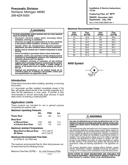
IntroductionFollow these instructions when installing, operating, or servicing the product.A 5 micrometer pre-filter installed immediately ahead of the filter, will greatly extend the life of the cartridge assembly up to twice the life expectancy in most cases. A pre-filter is also recommended to remove abnormally large amounts of liquid water and/or oil entering a coalescing filter.Application LimitsThese products are intended for use in general purpose compressed air systems only.Maximum Operating Pressure:kPa PSIG bar Plastic Bowl103415010.3Metal Bowlw/ Manual Drain172425017.2w/ Internal Auto Drain120717512.0Maximum Ambient Temperature:Metal Bowl w/ Manual Drain 74°C (165°F)All Others49°C (120°F)Maximum Recommended Flow Rate:50 SCFM @ 100 PSIG InletThe maximum recommended flow for other inlet pressures can be determined by the following formula:Maximum Flow Rate (SCFM) =50 x Inlet Pressure (PSIA)____________________114.7Maximum Recommended FlowsInlet FlowInlet Flow (PSIG)(SCFM)(PSIG)(SCFM)1010.89045.62015.110050.03019.511054.44023.812058.75028.213063.16032.614067.47036.915071.88041.3ANSI SymbolInstallation & Service Instructions:1C106Coalescing Filter, 3/4" NPTF ISSUED: November, 2003Supersedes:July, 1999Doc.# 1C106, ECN# 030539, Rev. 1WARNINGTo avoid unpredictable system behavior that can cause personal injury and property damage:•Disconnect electrical supply (when necessary) before installation, servicing, or conversion.•Disconnect air supply and depressurize all air lines connected to this product before installation, servicing, or conversion.•Operate within the manufacturer’s specified pressure,temperature, and other conditions listed in these instructions.•Medium must be moisture-free if ambient temperature is below freezing.•Service according to procedures listed in these instructions.•Installation, service, and conversion of these products must be performed by knowledgeable personnel who understand how pneumatic products are to be applied.•After installation, servicing, or conversion, air and electrical supplies (when necessary) should be connected and the product tested for proper function and leakage. If audible leakage is present, or the product does not operate properly, do not put into use.•Warnings and specifications on the product should not be covered by paint, etc. If masking is not possible, contact your local representative for replacement labels.WARNINGFAILURE OR IMPROPER SELECTION OR IMPROPER USE OF THE PRODUCTS AND/OR SYSTEMS DESCRIBED HEREIN OR RELATED ITEMS CAN CAUSE DEATH, PERSONAL INJURY AND PROPERTY DAMAGE.This document and other information from The Company, its subsidiaries and authorized distributors provide product and/or system options for further investigation by users having technical expertise. It is important that you analyze all aspects of your application, including consequences of any failure and review the information concerning the product or systems in the current product catalog. Due to the variety of operating conditions and applications for these products or systems, the user,through its own analysis and testing, is solely responsible for making the final selection of the products and systems and assuring that all performance, safety and warning requirements of the application are met.The products described herein, including without limitation, product features, specifications, designs, availability and pricing, are subject to change by The Company and its subsidiaries at any time without notice.EXTRA COPIES OF THESE INSTRUCTIONS ARE AVAIL ABL E FOR INCLUSION IN EQUIPMENT / MAINTENANCE MANUALS THAT UTILIZE THESE PRODUCTS. CONTACT YOUR LOCAL REPRESENTATIVE.Pneumatic DivisionRichland, Michigan 49083269-629-5000!!Coalescing Filter 3/4" NPTF1C106 Installation:1.Determine if the flow requirement is within the limitsrecommended for the filter.2.Do not install the filter in a location that would exposethe polycarbonate bowl to harmful fumes or fluids (seeCaution below).3.Check downstream piping for cleanness.4.Install the filter in a level (bowl down) position.Lock RingCAUTIONPolycarbonate bowls, being transparent and tough, are ideal for use with Filters and L ubricators. They are suitable for use in normal industrial environments, but should not be located in areas where they could be subjected to direct sunlight, an impact blow, nor temperatures outside of the rated range. As with most plastics, some chemicals can cause damage. Polycarbonate bowls should not be exposed to chlorinated hydro-carbons, ketones, esters and certain alcohols. They should not be used in air systems where compressors are lubricated with fire-resistant fluids, such as phosphate ester and di-ester types.Metal bowls are recommended where ambient and/or media conditions are not compatible with polycarbonate bowls. Metal bowls resist the action of most such solvents, but should not be used where strong acids or bases are present or in salt laden atmospheres. Consult the factory for specific recommendations where these conditions exist. TO CL EAN POLYCARBONATE BOWL S, USE MIL D SOAP AND WATER ONLY! DO NOT use cleansing agents such as acetone, benzene, carbon tetrachloride, gasoline, toluene, etc., which are damaging to this plastic.OperationAfter start-up – inspect points of delivery to insure that the filtration is effective. If there is evidence of airline contamination, check the following:1.Downstream piping – piping often contains residue fromprevious use or storage.2.Flow – exceeding the maximum recommended flow candrastically reduce the filter’s efficiency.3.Check to see that the filter is in a level position.4.Inspect filter and cartridge assembly for damage. Maintenance1.Periodically drain filter. Do not allow the liquid to reach thecartridge assembly.2.The life of the filter is dependent upon the amount of dirt inthe air stream; replacing the cartridge assembly is recommended if the pressure drop exceeds 10 psi.3.T o replace cartridge assembly, remove lock ring and bowl.Unscrew cartridge assembly counter-clockwise. Remove o-ring and discard. Replace with new cartridge assembly Kit Part #035367522 (includes new o-ring). T o reassemble, place o-ring into top of cartridge assembly and reassemble unit. Avoid gripping the sponge sleeve when installing a new cartridge assembly.4.The polycarbonate bowl should be cleaned only with amild household detergent or white kerosene.!Bowl guards are recommended for added protection of polycarbonate bowls where chemical attack may occasionally occur.。
Parker Hannifin Corporation 压缩空气和气体过滤器手册说明书
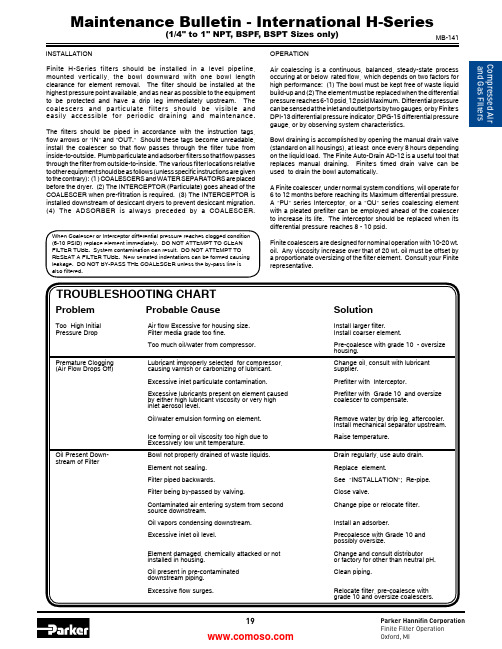
19Parker Hannifin Corporation Finite Filter Operation Oxford, MIProblemProbable CauseSolutionToo High Initial Air flow Excessive for housing size. Install larger filter.Pressure Drop Filter media grade too fine.Install coarser element.Too much oil/water from compressor. Pre-coalesce with grade 10 - oversizehousing.Premature Clogging Lubricant improperly selected for compressor, Change oil, consult with lubricant(Air Flow Drops Off) causing varnish or carbonizing of lubricant. supplier.Excessive inlet particulate contamination. Prefilter with Interceptor.Excessive lubricants present on element caused Prefilter with Grade 10 and oversize by either high lubricant viscosity or very high coalescer to compensate.inlet aerosol level.Oil/water emulsion forming on element. Remove water by drip leg, aftercooler.Install mechanical separator upstream. Ice forming or oil viscosity too high due to Raise temperature.Excessively low unit temperature.Oil Present Down- Bowl not properly drained of waste liquids. Drain regularly, use auto drain. stream of FilterElement not sealing. Replace element.Filter piped backwards.See "INSTALLATION"; Re-pipe. Filter being by-passed by valving.Close valve.Contaminated air entering system from second Change pipe or relocate filter. source downstream.Oil vapors condensing downstream. Install an adsorber.Excessive inlet oil level. Precoalesce with Grade 10 andpossibly oversize.Element damaged, chemically attacked or not Change and consult distributor installed in housing.or factory for other than neutral pH. Oil present in pre-contaminated Clean piping.downstream piping. Excessive flow surges. Relocate filter, pre-coalesce withgrade 10 and oversize coalescers.Maintenance Bulletin - International H-Series(1/4" to 1" NPT , BSPF , BSPT Sizes only)When Coalescer or Interceptor differential pressure reaches clogged condition (6-10 PSID) replace element immediately. DO NOT ATTEMPT TO CLEAN FILTER TUBE. System contamination can result. DO NOT ATTEMPT TO RESEAT A FILTER TUBE. New serrated indentations can be formed causing leakage. DO NOT BY-PASS THE COALESCER unless the by-pass line is also filtered.Finite H-Series filters should be installed in a level pipeline, mounted vertically, the bowl downward with one bowl length clearance for element removal. The filter should be installed at the highest pressure point available, and as near as possible to the equipment to be protected and have a drip leg immediately upstream. The coalescers and particulate filters should be visible and easily accessible for periodic draining and maintenance.The filters should be piped in accordance with the instruction tags, flow arrows or "IN" and "OUT." Should these tags become unreadable,install the coalescer so that flow passes through the filter tube from inside-to-outside. Plumb particulate and adsorber filters so that flow passes through the filter from outside-to-inside. The various filter locations relative to other equipment should be as follows (unless specific instructions are given to the contrary): (1 ) COALESCERS and WATER SEPARATORS are placed before the dryer. (2) The INTERCEPTOR (Particulate) goes ahead of the COALESCER when pre-filtration is required. (3) The INTERCEPTOR is installed downstream of desiccant dryers to prevent desiccant migration. (4) The ADSORBER is always preceded by a COALESCER.INSTALLATIONOPERATIONAir coalescing is a continuous, balanced, steady-state process occuring at or below rated flow, which depends on two factors for high performance: (1) The bowl must be kept free of waste liquid build-up and (2) The element must be replaced when the differential pressure reaches 6-10 psid, 12 psid Maximum. Differential pressure can be sensed at the inlet and outlet ports by two gauges, or by Finite's DPI-13 differential pressure indicator, DPG-15 differential pressure gauge, or by observing system characteristics.Bowl draining is accomplished by opening the manual drain valve (standard on all housings), at least once every 8 hours depending on the liquid load. The Finite Auto-Drain AD-12 is a useful tool that replaces manual draining. Finite's timed drain valve can be used to drain the bowl automatically.A Finite coalescer, under normal system conditions, will operate for 6 to 12 months before reaching its Maximum differential pressure. A "PU" series Interceptor, or a "QU" series coalescing element with a pleated prefilter can be employed ahead of the coalescer to increase its life. The interceptor should be replaced when its differential pressure reaches 8 - 10 psid.Finite coalescers are designed for nominal operation with 10-20 wt. oil. Any viscosity increase over that of 20 wt. oil must be offset by a proportionate oversizing of the filter element. Consult your Finite representative.MB-141TROUBLESHOOTING CHARTParker Hannifin Corporation Finite Filter Operation Oxford, MIAssembly Drawing/Parts List1/4" to 1" NPT/BSPF/BSPTRodEnd Cap O-RingHeadElementBowl Brass NutDrain Bushing O-Ring (drain) Shell - 40605 Spring - 40006Piston - 40604 Diaphram - 415691Parker Hannifin Corporation Finite Filter Operation Oxford, MIProblemProbable CauseSolution Too High Initial Air flow Excessive for housing size. Install larger filter.Pressure Drop Filter media grade too fine.Install coarser element.Too much oil/water from compressor. Precoalesce with grade 10 - oversizehousing.Premature Clogging Lubricant improperly selected for compressor, Change oil, consult with lubricant(Air Flow Drops Off) causing varnish or carbonizing of lubricant. supplier.Excessive inlet particulate contamination. Prefilter with Interceptor.Excessive lubricants present on element caused Prefilter with Grade 10 and oversize by either high lubricant viscosity or very high coalescer to compensate.inlet aerosol level.Oil/water emulsion forming on element. Remove water by drip leg, aftercooler.Install mechanical separator upstream. Ice forming or oil viscosity too high due to Raise temperature.Excessively low unit temperature.Oil Present Down- Bowl not properly drained of waste liquids. Drain regularly, use auto drain. stream of FilterElement not sealing. Replace element.Filter piped backwards.See "INSTALLATION"; Re-pipe. Filter being by-passed by valving.Close valve.Contaminated air entering system from second Change pipe or relocate filter. source downstream.Oil vapors condensing downstream. Install an adsorber.Excessive inlet oil level. Precoalesce with Grade 10 andpossibly oversize.Element damaged, chemically attacked or not Change and consult distributor installed in housing.or factory for other than neutral pH. Oil present in precontaminated Clean piping.downstream piping. Excessive flow surges. Relocate filter, precoalesce withgrade 10 and oversize coalescers.Maintenance Bulletin - International H-Series(1 1/4" to 3" NPT , BSPF , BSPT Sizes only)When Coalescer or Interceptor differential pressure reaches clogged condition (6-10 PSID) replace element immediately. DO NOT ATTEMPT TO CLEAN FILTER TUBE. System contamination can result. DO NOT BY-PASS THE CO -ALESCER unless the by-pass line is also filtered.INSTALLATIONOPERATIONAir coalescing is a continuous, balanced, steady-state process occurring at or below rated flow, which depends on two factors for high performance: (1) The bowl must be kept free of waste liquid buildup and (2) The element must be replaced when the differential pressure reaches 6-10 psid, 12 psid Maximum. Differential pressure can be sensed at the inlet and outlet ports by two gauges, or by Finite's DPI-13 differential pressure indicator, DPG-15 differential pressure gage, or by observing system characteristics.Bowl draining is accomplished by opening the manual drain valve (standard on all housings), at least once every 8 hours depending on the liquid load. The Finite Auto-Drain AD-12 is a useful tool that replaces manual draining. Finite has an assortment of electrically timed drain valves that can be used to drain the bowl automatically. A Finite coalescer, under normal system conditions, will operate for 6 to 12 months before reaching its Maximum differential pressure. A "PU" series Interceptor, or a "QU" series coalescing element with a pleated prefilter can be employed ahead of the coalescer to increase its life. The interceptor should be replaced when its differential pres -sure reaches 8 - 10 PSID.Finite coalescers are designed for nominal operation with 10-20 wt. oil. Any viscosity increase over that of 20 wt. oil must be offset by a proportionate oversizing of the filter element. Consult your Finite representative.Finite H-Series filters should be installed in a level pipeline, mounted vertically, the bowl downward with one bowl length clearance for element removal. The filter should be installed at the highest pressure point available, and as near as possible to the equipment to be protected and have a drip leg immediately upstream. The coalescers and particulate filters should be visible and easily accessible for periodic draining and maintenance. Filters should be piped according to these instructions also following the flow direction label on the filters.Filters up to and including 2" connection sizes flow as follows: Coalescers/WS : from port 1 to port 2 Interceptors : from port 2 to port 1 Adsorbers : from port 2 to port 1.Filters with connection sizes 2 1/2" and 3" flow as follows: Coalescers/WS : from port 1 to port 2 Interceptors : from port 1 to port 2 Adsorbers : from port 1 to port 2.The following are recommended filter locations relative to other com -pressed air equipment (unless specific instructions are given to the contrary):(1) COALESCERS and WATER SEPARATORS (WS) (liquid removal) are placed before the dryer.(2) The INTERCEPTOR (particulate removal) should be installed ahead of the COALESCER when prefiltration is required.(3) The INTERCEPTOR (particulate removal) can also be installed downstream of desiccant dryers to prevent desiccant migration. (4) The ADSORBER (vapor removal) is always preceded by a COALESCER.DANGERFilter housings must be depressurized before performing any maintenance activities.!MB-143TROUBLESHOOTING CHARTParker Hannifin Corporation Finite Filter Operation Oxford, MIShell - 40605 Spring - 40006Piston - 40604 Diaphram - 41569RodEnd CapO-RingHeadElementBowlBrass Nut Drain Bushing O-Ring (drain)。
亚特兰茅斯公司压缩空气过滤器产品说明书
Compressed air filtersCOMMITTED TO SUPERIOR PRODUCTIVITYIn-house development & testingSince 1998, our dedicated filtration team is responsible for in-house development of cutting-edge filtration solutions. This results in expert know-how of filtration mechanisms, state-of-the-art test facilities and breakthrough innovations. For many years, our filtration team has cooperated closely with the University of Karlsruhe, a leading institute in research of filtration mechanisms.Rigorous quality controlTo ensure the highest standards, all Atlas Copco products are subjected to rigorous quality control testing. The entire filter range is produced in-house, on the most advanced production lines, using the most stringent methods in the industry. You can rest assured at all times that strict certification and testing procedures are conducted to ensure our filtration products meet the highest standards.Cast design6 grades 13 sizes 9 → 550 l/s19 → 1,200 cfm850 → 1,100 l/s 1,801 →DDp+H Dry dust Oil aerosol Wet dust Oil vaporWater dropsMicro-organisms m eCERTIFIED PERFORMANCEAtlas Copco filters are qualified according to the ISO 8573-1:2010 standard. This is the latest edition of the standard. Beware of filters that comply with earlier editions, such as ISO 8573-1:1991 or ISO 8573-1:2001. The difference is inferior quality of the delivered compressed air. This qualification is a result of our filters being tested according to ISO 12500-1:2007, ISO 12500-2:2007, and ISO 12500-3:2009. These specify the test layout, test procedures and inlet conditions required for testing coalescing filters, vapor filters, and solid particle filters used in compressed air systems, to determine their effectiveness in removing oil aerosol, oil vapor and solid particles. The measurements of the air purity downstream the filter for each specific contaminant have been performed according to the test methods described in respectively ISO 8573-2:2007, ISO 8573-5:2001 and ISO 8573-4:2001. Tests have been conducted in-house as well as in external labs, and are independently validated by TÜV.ISO certificationAtlas Copco’s filters have been fully tested and qualified according to the following ISO standards:Certified peace of mind• ISO 8573-1:2010: Compressed air - Contaminants and purity classes• ISO 8573-2:2007: Compressed air - Test method for oil aerosol content• ISO 8573-4:2001: Compressed air - Test method for dust• ISO 8573-5: 2001: Compressed air - Test method for oil vapor and organic solvent content• ISO 12500-1:2007: Filters for compressed air - test methods - oil aerosols• ISO 12500-2:2007: Filters for compressed air - test methods - oil vapors• ISO 12500-3:2009: Filters for compressed air - test methods - particulatesA SOLUTION FOR EVERY APPLICATIONAt different points of use, different compressed air purities might be needed, depending on the application. The various air purity classes are provided in the table below, which clearly shows the various Atlas Copco filters and dryers that meet all the different classes.* Please contact your Atlas Copco sales representative.UD+ SERIESTwo-in-one oil coalescing filters with supreme energy savingsUD+ filters efficiently reduce oil aerosol, wet dust and water drops in your compressed air stream to protect your investment, equipmentand processes. The UD+ combines two filtration steps (DD+ and PD+) into one, a unique technology to meet the high-quality requirements of diverse applications and provide ultimate energy savings.PerformanceSave spaceapplications where space is at a premium.Save moneyto conventional filters.* Inlet oil concentration = 10 mg/m³. Oil = oil aerosol and liquid.• EWD electronic drain with no loss of compressed air and , F and larger).Wall mounting kitCBACCBAAB850+T & 1100+T 9+ – 550+550+F – 8000+FDD(+)/PD(+) SERIESHigh performance oil coalescing filtersDD(+) and PD(+) filters efficiently reduce oil aerosol, wet dust and water drops in your compressed airstream. These could come from the lubrication of the compressor element, the intake air, and the compressor installation itself. These innovative filtration solutions are engineered to cost-effectively provide the best air purity and meet today’s increasing quality demands.Easy maintenanceMonitoring of energy use* Inlet oil concentration = 10 mg/m³. Oil = oil aerosol and liquid.Performance850+T & 1100+T 9+ – 550+550+F – 8000+FAB(EWD is optional on sizes 10+ - 550+ l/s and 12-690 l/s; standard on sizes ≥550F).EWD electronic drain• Multiply the nominal capacity of the selected filter with the corresponding correction CCCBBAADDp(+)/PDp(+) SERIESOptimal dry dust filtrationDDp(+) and PDp(+) filters efficiently prevent dust,particulates and micro-organisms arising from corrosion,dirt and adsorption material from entering yourcompressed air stream. These innovative filtrationsolutions are engineered to cost-effectively providethe best air purity and meet today’s increasingquality demands.Easy maintenanceMonitoring of energy use PerformanceVoltage-free contactCCBBAAC9+ – 550+550+F – 8000+F850+T & 1100+T ABQDT SERIESActivated carbon towers for optimal oil vapor filtrationThe high efficiency activated carbon tower is capable of removing hydrocarbons, odors and oil vapor from compressed air.The activated carbon will, by the use of adsorption,reduce the residual oil content to lower than 0.003 mg/m³.The pressure drop is low and stays minimal during the filter’s lifetime.Performance* After UD+ or DD+/PD+ with inlet oil concentration of 10 mg/m³.CertificationISO 8573-5:2001AABBCCUD+ & QDT: the winning combinationUD+For other compressed air inlet pressures, please multiply the filter capacity by the following correction factor (Kp):QDT 20-310QD(+) SERIESHigh performance oil vapor filtersQD(+) filters efficiently reduce hydrocarbons, odors and oilvapor in your compressed air stream to protect your investment, equipment and processes. The activated carbon layers will, by the use of adsorption, reduce the residual oil content to less than 0.003 mg/m³. The pressure drop is lowand stays minimal during the lifetime of the filter.* After UD+ or DD(+)/PD(+) with inlet oil concentration of 10 mg/m³.PerformanceOptions(DD & PD only).SFA SERIESSilicone-free removal of oil aerosol, dust and oil vaporSuperb air purity is a prerequisite to safeguard your instruments and end product. Our silicone-free SFA filters efficiently prevent dry and wet dust, particulates, oil aerosol and water drops from entering your compressed air system. The SFA series is manufactured and treated according to the high standards of silicone-free equipment, and certified bythe Fraunhofer Institute as guaranteed silicone-free.* Nominal pressure: 7 bar(e)/102 psig; temperature: 20°C, 68°F.• Painting • AutomotiveThe performance of the SFA filters is comparable to the performance of the + range filters (please refer to pages 8, 10 and 14).CABH SERIESGuaranteed air purity up to 350 barHigh pressure filters efficiently reduce oil aerosol, dust and wet dust, particulates, water droplets and oil vapor in your compressed air stream to protect your investment, equipment and processes. Our innovative high pressure filtration solutions are engineered to cost effectivelyprovide the best air purity and meet today’s increasing quality demands up to working pressures of 350 bar. All high pressure filter housings are hydraulically tested to ensure safe and reliable operation at all times. A pressure test certificate accompanies each filter.Applications• Chemical• Food & beverage • Manufacturing • Military • Oil & gasPerformanceAlways install a liquid water separation system in front of a filter. Water separation is not needed in the high pressure line if there is a sufficiently low PDP in the low pressure line (e.g. nitrogen skid, low pressure line with adsorption dryer).* Inlet oil concentration = 10 mg/m³. Oil = oil aerosol and liquid.** After DD(+)/PD(+) with inlet oil concentration of 10 mg/m³.DDH, DDHp, PDH, PDHp, QDH20 bar Aluminum50 bar Aluminum1250+1725+1925+3200+50 bar Stainless Steel1000+1700+2040+3400+100 bar Stainless Steel1200+1700+Example• Working pressure 300 bar(g), compressed air flow 500 m³/h.• Multiply the nominal capacity of the selected filter with thecorresponding correction factor at the required working pressure to obtain the capacity at working pressure:- Size 510+: 510 m³/h * 0.96 = 490 m³/h => the 510+ filter sizeis not large enough.- Size 750+: 750 m³/h * 0.96 = 720 m³/h => the 750+ filter sizeis the size to select.CBAMV SERIESMedical vacuum filters for optimal protectionof man and machineMedical vacuum filters are installed at the inlet of the vacuum pump toremove any liquid, solid or bacterial contamination which could damagethe vacuum pump and biologically infect the downstream air.Our innovative medical vacuum filtration solutions complywith HTM medical standards.Performance* In accordance with BS 3928-1969.Applications• Medical• Dental• VeterinaryCorrection factorsB CA Drain flask2935 0932 44 © 2018, A t l a s C o p c o A i r p o w e r N V , B e l g i u m . A l l r i g h t s r e s e r v e d . D e s i g n s a n d s p e c i fi c a t i o n s a r e s u b j e c t t o c h a n g e w i t h o u t n o t i c t i o n . R e a d a l l s a f e t y i n s t r u c t i o n s i n t h e m a n u a l b e f o r e u s a g e .。
压缩空气精密过滤器使用方法

压缩空气精密过滤器使用方法
2015-03-27 15:00 系统分类:经验体会专业分类:建筑电气浏览数:105
1、压缩空气精密过滤器以“先粗后精”原则组合配置,顺序不能颠倒。
2、实际通过过滤器的压缩空气流量、压力及温度不能超过铭牌规定值。
3、安装时须注意分清过滤器的进、出口位置。
4、过滤器安装应对地垂直。
留有一定的离地高度,便于调换滤芯。
5、下列情况之一出现时,应当更换滤芯:
a.过滤效果明显恶化;
b.压差表示值超过0.07MPa;(注:滤芯初始压降<0.015Mpa)
c.超过使用时限:一般是8000h。
6、不带自动排水器的过滤器,应定时打开球阀排除滤壳积水。
通常每班不少于1—2次。
7、过滤器进气温度不超过66℃。
8、若工作压力低于标准值(0.7MPa)时,过滤器的实际处理能力应按标准进行修正。
Parker OIL-X系列压缩空气过滤器说明书
|series of compressed air filters, taking efficiency to a different level.Built on Parker’s worldwide expertise in filtration, the OIL-X range has been developed to ensure consistent outstanding air quality, guaranteed for 12 months, and third-party validated to meet ISO 8573-1.The Parker domnick hunter OIL-X range of die-castcompressed air filters has been designed from the outset to meet the air quality requirements of all editions of ISO8573-1, when validated in accordance with the stringent requirements of ISO12500-1.An efficient and cost effective manufacturingprocess is a major factor in maintaining the profitability and growth of your business. All Parker domnick hunter products are designed to not only minimize the use of compressed air and electrical energy in their operation, but also tosignificantly reduce the operational costs of the compressor by minimizing pressure losses.OIL-X filters incorporate a number of unique and patenteddesign features to minimize differential pressure and provide a filter and element combination where the differential pressure starts low and stays low to maximize energy savings and provide the lowest lifetime costs without compromising air quality.FOCUSED ON EFFIC I ENCYParker domnick hunter OIL-X a new The Parker domnick hunter OIL-X has been developed with a design philosophy of simplicity, compatibility and usability, but above all validated air quality. OIL-X is available in four different variants: water separation, coalescing, dry particulate and oil vapor removal.Features• For the removal of water and oil aerosols,atmospheric dirt and solid particles, rust,pipescale and micro-organisms• Coalescing filter performance tested tothe stringent requirements of ISO12500-1and ISO8573-2• Dry particulate filter performance testedin accordance with the requirements ofISO8573-4• Unique filter elementWith a specialist construction and unique design forreduced air flow velocity, reduced pressure loss,increased dirt holding capacity, and improved efficiencyincluding a 12-month air quality guarantee. Energy efficientmedia - 1.8 psig saturated pressure drop.• Flow management systemSpecially engineered ‘bell mouth’, with 90-degree elbow, flowdistributor and conical flow diffuser, to promote a consistent,optimum air flow, contributing towards maximum efficiency,reduced differential pressure and lower energy consumption. • Differential pressure indicatorIndication of required change out of element.• Filter housingDesigned to allow easy maintenance and elementreplacement, and covered by a 2-year guarantee, for reduceddowntime, service cost and peace of mind.• Flexible connectionsA wide range of port sizes and filter connections, foradded flexibility and time saving.• Epoxy coatingFinished with alocrom corrosion protection and a tough, drypowder epoxy coating for a high quality feel with the reassurance of durability.Your air quality has been guaranteed for 1 year and will be renewed at every annual filter element change.Annual filter element changes ensure:1.8 psig operational differential pressure Validated performance you can rely onBuilt on Parker’s worldwide expertise in filtration, the Parker domnick hunter OIL-X range has been developed to ensure consistent outstanding air quality, guaranteed for 12 months - and third-party validated to meet ISO 8573-1 (the international standard of compressed air quality).Combining the unique filter element with a specially designed advanced air flow management system, the Parker domnick hunter OIL-X range is engineered to not only deliver air quality in accordance with ISO 8573-1 classifications, but it does so with an extremely low differential pressure – ensuring maximum efficiency Combining the unique filter element with a specially designed advanced air flow management system, the Parker domnick hunter OIL-X range is engineered to not only deliver air quality in accordance with ISO 8573-1 classifications, but it does so with the lowest differential pressure on the market-ensuring maximum efficiency One Year Air Quality GuaranteeOIL-X Water Separators Technical DataProduct Selection Stated flows are for operation at 102 psi g (7 bar g) with reference to 68°F (2014.5 psi (1 bar), 0% relative water vapor pressure.WSP010ANFX-US WSP010BNFX WSP010CNFX WSP015CNFX WSP020DNFX WSP025DNFX WSP025ENFX WSP030GNFX WSP035GNFX WSP040HNFX WSP045INFX WSP050INFX WSP055JNFX WSP060KNFX Applying Correction FactorsTo correctly select a filter model, the flow rate of the filter must be adjusted for the minimum operating pressure of the system.• To correctly select a filter model, the flow rate of the filter must be adjusted for the minimum operatingpressure of the system.• Obtain the minimum operating pressure and maximum compressed air flow rate at the inlet of the filter.• Select the correction factor for minimum operating pressure from the CFP table (always round down e.g. for 73.2 psi, use 73 psi correction factor).• Calculate the minimum filtration capacity : Minimum Filtration Capacity = Compressed Air Flow Rate x CFP.• Using the minimum filtration capacity, select a filter model from the flow rate tables above (filter selected must have a flow rate equal to or greater than the minimum filtration capacity.Filtration Grade WSP010-WSP050WSP060Product SelectionAA P 030G N F IWS AO AA ACSGradeFiltration Grade Filter Type Drain Type Min Operating Pressure Max Operating Pressure Min Operating Temperature Max Operating Temperature psi g bar g psi g bar g °F °C °F °C AO/AA Coalescing Float 1512321635217680AO/AA Dry Particulate Manual 15129020352212100ACSOil Vapor RemovalManual1512902035212250Filtration Grade WSAOAAACSFilter TypeBulk Liquid RemovalCoalescing &Dry Particulate Coalescing & Dry ParticulateOil Vapor RemovalParticle Removal (inc water & oil aerosols)N/A Down to 1 micron Down to 0.01 micronN/A Max Remaining Oil Content at 21°C (70°F)N/A 0.5mg/m³0.5 ppm(w)0.01mg/m³0.01 ppm(w)0.003 mg/m³0.003 ppm(w)Filtration Efficiency >92%99.925%99.9999%N/A Test Methods UsedISO8573.9ISO8573.2ISO8573.4ISO12500-1ISO8573.2ISO8573.4ISO12500-1ISO8573.5ISO12500-1 Inlet Challenge ConcentrationN/A 40mg/m³10mg/m³N/AInitial Dry Differential Pressure N/A <1.0psi (70 mbar)<1.0psi (70 mbar)<2.0psi (140 mbar)Initial Saturated Differential PressureN/A <1.8psi (125 mbar)<1.8psi (125 mbar)N/AChange Element Every N/A 12 months 12 monthsWhen Oil Vapor is DetectedPrecede with Filtration GradeN/AWS (for bulk liquid)AOAALine Pressure Correction Factor Pressure (CFP)psi g bar g 151 2.65292 1.87443 1.53584 1.32735 1.18876 1.081007 1.0011680.9413190.88145100.84160110.80174120.76189130.73203140.71218150.68232160.66Manual drain filters only 248170.64263180.62277190.61290200.59Product SelectionStated flows are for operation at 102 psi g (7 bar g) with reference to 68°F (20ºC), 14.5 psi (1 bar), 0% relative water vapor pressure.Applying Corrective Factors• To correctly select a filter model, the flow rate of the filter must be adjusted for the minimum operating pressure of the system.• Obtain the minimum operating pressure and maximum compressed air flow rate at the inlet of the filter .• Select the correction factor for minimum operating pressure from the CFP table (always round down e.g. for 73.2 psi, use 73 psi correction factor).• Calculate the minimum filtration capacity : Minimum Filtration Capacity = Compressed Air Flow Rate x CFP .• Using the minimum filtration capacity, select a filter model from the flow rate tables above (filter selected must have a flow rate equal to or greater than the minimum filtration capacity.ModelPort Conn.Flow RatesReplacementElements scfm L/s m 3/min m 3/hr GRADE P010AN(*)1/4”21100.636P010 GRADE GRADEP010BN(*) 3/8”21100.636P010 GRADE GRADE P010CN(*) 1/2”21100.636P010 GRADE GRADE P015CN(*) 1/2”4220 1.272P015 GRADE GRADE P020CN(*)1/2”6430 1.8108P020 GRADE GRADE P020DN(*) 3/4”6430 1.8108P020 GRADE GRADEP025DN(*) 3/4”12760 3.6216P025 GRADE GRADE P025EN(*)1”12760 3.6216P025 GRADE GRADE P030GN(*) 1-1/2”233110 6.6396P030 GRADE GRADE P035GN(*)1-1/2”3391609.6576P035 GRADE GRADEP040HN(*) 2”46622013.2792P040 GRADE GRADE P045IN(*) 2-1/2”69933019.11188P045 GRADE GRADE P050IN(*) 2-1/2”91143025.91548P050 GRADE GRADE P055IN(*)2-1/2”131462037.32232P055 GRADE GRADE P055JN(*)3”131462037.32232P055 GRADE GRADEP060KN(*)4”2119100060.03600060 GRADE(*) = Replace with (F) when ordering AO/AA coalescing filters, (M) when ordering AO/AA dry particulate filters or (M) when ordering ACS oil vapor removal filters.= Replace with (I) for differential Pressure Indicator . Replace with (X) for no differential pressure indicator.*AO/AA only available with differential pressure indicator (I). WS/ACS only available without differential pressure indicator (X).OIL-X FiltersTechnical DataModel Pipe Size Height (H)Width (W)Depth (D)(a)(b)(c)(d)Weight mm ins mm ins mm ins mm ins mm ins mm ins mm ins kg lbs WS / P010A 1/4”1807.0976 2.9966 2.60154 6.150 1.9732 1.338 1.50.61 1.34WS / P010B 3/8”1807.0976 2.9966 2.60154 6.150 1.9732 1.338 1.50.61 1.34WS / P010C 1/2”1807.0976 2.9966 2.60154 6.150 1.9732 1.338 1.50.61 1.34WS / P015C 1/2”238.59.3689 3.583.5 3.292028.050 1.9732 1.338 1.5 1.16 2.55P020C 1/2”238.59.3689 3.583.5 3.292028.050 1.9732 1.338 1.5 1.12 2.58WS / P020D 3/4”238.59.3689 3.583.5 3.292028.050 1.9732 1.338 1.5 1.12 2.58WS / P020D 3/4”22710.9120 4.72114.5 4.52329.170 2.7632 1.338 1.5 2.21 4.86WS / P025E 1”22710.9120 4.72114.5 4.52329.170 2.7632 1.338 1.5 2.21 4.86WS / P030G 1-1/2”36714.45120 4.72114.5 4.532312.770 2.7632 1.338 1.5 2.68 5.91WS / P035G 1-1/2”53120.9164 6.46156 6.1038415.1100 3.9468 2.6838 1.5 6.9015.20WS / P040G 2”62324.5164 6.46156 6.1047618.7100 3.9468 2.6838 1.57.3016.10WS / P045H 2-1/2”62324.5164 6.46156 6.1047618.7100 3.9468 2.6838 1.57.1015.65WS / P050I 2-1/2”74529.31927.561837.2058723.1120 4.7268 2.6838 1.510.3022.71P055I 2-1/2”93536.81927.561837.2077230.4120 4.7268 2.6838 1.515.3033.73WS / P055J3”93536.81927.561837.2077230.41204.72682.68381.515.3033.73Diagram offilter dimensionsParker Hannifin CorporationIndustrial Gas Filtration and Generation Division 4087 Walden Avenue Lancaster, NY 14086phone 800 343 /igfg© 2018 Parker Hannifin Corporation. Product names are trademarks or registered trademarks of their respective companies BRO_OIL-X_102018North AmericaCompressed Air TreatmentIndustrial Gas Filtration and Generation DivisionLancaster, NY 716 686 6400/igfg Haverhill, MA 978 858 0505/igfgEngine FiltrationRacorModesto, CA 209 521 7860/racor Holly Springs, MS 662 252 2656/racorHydraulic FiltrationHydraulic & Fuel FiltrationMetamora, OH 419 644 4311/hydraulicfilter Laval, QC Canada 450 629 9594 VelconColorado Springs, CO 719 531 5855 Process Filtrationdomnick hunter Process Filtration SciLogOxnard, CA 805 604 3400/processfiltrationWater PurificationVillage Marine, Sea Recovery, Horizon Reverse OsmosisCarson, CA 310 637 3400/watermakersEuropeCompressed Air Treatmentdomnick hunter Filtration & SeparationGateshead, England +44 (0) 191 402 9000 /dhfnsParker Gas SeparationsEtten-Leur, Netherlands +31 76 508 5300/dhfnsHiross AirtekEssen, Germany +49 2054 9340/hzfd Padova, Italy+39 049 9712 111 /hzfdEngine Filtration & Water PurificationRacorDewsbury, England +44 (0) 1924 487 000 /rfdeRacor Research & DevelopmentStuttgart, Germany +49 (0)711 7071 290-10Hydraulic FiltrationHydraulic FilterArnhem, Holland +31 26 3760376/hfde Urjala, Finland +358 20 753 2500Condition Monitoring Parker KittiwakeWest Sussex, England +44 (0) 1903 731 470 Process Filtrationdomnick hunter Process Filtration Parker Twin Filter BVBirtley, England+44 (0) 191 410 5121/processfiltrationAsia PacificAustraliaCastle Hill, Australia +61 2 9634 7777/australiaChinaShanghai, China +86 21 5031 2525 /chinaIndiaChennai, India +91 22 4391 0700 /indiaParker FowlerBangalore, India +91 80 2783 6794JapanTokyo, Japan +81 45 870 1522/japanKoreaHwaseon-City +82 31 359 0852/koreaSingaporeJurong Town, Singapore +65 6887 6300/singaporeThailandBangkok, Thailand +66 2186 7000/thailandLatin AmericaParker Comercio Ltda. Filtration DivisionSao Paulo, Brazil +55 12 4009 3500 /brPan American DivisionMiami, FL 305 470 8800/panamAfricaAeroport Kempton Park, South Africa +27 11 9610700/africaWorldwide Filtration Manufacturing Locations。
精密过滤器说明书
精密过滤器用户手册目录工作原理1性能特点1原理特点2结构形式2主要技术参数3安装使用说明3操作说明4滤芯的更换方法5反渗透膜元件的清洗6滤芯的清洗8一、工作原理精密过滤器又称保安过滤器。
壳体采用优质不锈钢制作而成,滤芯采用成型的滤材(聚丙烯纤维熔喷或线绕蜂房),在压力的作用下,使原液通过滤材,滤渣留在滤材上,滤液透过滤材流出,能有效去除水中杂质、沉淀物和悬浮物、细菌,从而达到过滤的目的。
精密过滤是采用成型的滤材,在压力的作用下,使原液通过滤材,滤渣留在滤材壁上,滤液透过滤材流出,从而达到过滤目的。
成型的滤材有:滤布、滤网、滤片、烧结滤管、线绕滤芯、熔喷滤芯、微孔滤芯及多功能滤芯。
因滤材的不同,过滤孔径也不相同。
精密过滤是介于砂滤(粗滤)与超滤之间的一种过滤,过滤孔径一般在0.01-120um范围。
同种形式的滤材,按外形尺寸又分为不同的规格。
线绕滤芯(又称蜂房滤芯)有两种:一种是聚丙烯纤维-聚丙烯骨架过滤,最高使用温度60℃;另一种是脱脂棉纤维-不锈钢骨架滤芯,最高使用温度120℃。
熔喷滤芯是以聚丙烯为原料,采用熔喷工艺形成的滤材,最高工作温度60℃。
精密过滤可去除水中的悬浮物、某些胶体物质和细小颗粒物等。
二、性能特点1、过滤精度高,滤芯孔径均匀。
2、过滤阻力小,通量大、截污能力强,使用寿命长。
3、滤芯材料洁净度高,对过滤介质无污染。
4、耐酸、碱等化学溶剂。
5、强度大,耐高温,滤芯不易变形。
6、价格低廉,运行费用低,易于清洗,滤芯可更换。
三、原理特点本公司生产的精密过滤器, 是蜂房式管状滤芯过滤器, 适用于对含悬浮物或机械杂质较低的水进一步净化。
为其后的设备提供良好的进水条件。
蜂房式管状滤芯,利用其特定工艺形成的外疏内密的蜂窝状结构这一优良的过滤特性,完成对被处理水的固液相分离过程,达到满意的制水效果。
但随着制水周期的递增,滤芯因受截留物的污染,其运行阻力会随之上升, 当设备运行的进、出水压差比初始压差升高0.15Mpa时,应及时更换滤芯。
压缩空气精密过滤器使用说明书
压缩空气精密过滤器使用说明书杭州超滤净设备有限公司尊敬的用户,为了更好更准确的使用本机器,请您在使用机器前认真阅读本说明书,并严格按照说明书上的使用要求去做。
如果您的机器遇到故障,请认真参照说明书中所列条目对照检修,也可与我们的授权机构或直接拨打售后服务热线8寻求帮助;对您的机器进行及时的保养,将更好的发挥它的性能。
希望本产品在您的工作给您带来便利,谢谢您的支持与合作!过滤器是利用物理阻隔技术来分离介质中其他成分的一种设备。
空气过滤器是用来过滤空气中固体微粒、水滴及油雾等气溶胶类杂质,使空气获得清净的主要设备。
过滤器结构图精密过滤器的性能与安装性能:安装:图1、图2所示在一个完整的压缩空气净化系统中,各级过滤器的安装次序。
图3为单支过滤器的标准配置。
1-空压机2-后部冷却器3-贮气罐4-FC级离心式油水分离器5-冷冻式干燥机6-FT级主管路过滤器7-FA级微油雾过滤器8-FH级除臭活性炭过滤器图1 过滤器与冷干机的标准安装次序1-空压机 2-后部冷却器 3-贮气罐 4-FC 级离心式油水分离器5-FA 级微油雾过滤器 6-吸干机7-FT 级主管路过滤器 8-FH 级除臭活性炭过滤器 图2 过滤器与吸干机的标准安装次序注意事项:1、过滤器以“先粗后精”原则组合配置,顺序不能颠倒。
2、实际通过过滤器的压缩空气流量、压力及温度不能超过铭牌规定值。
3、安装时须注意分清过滤器的进、出口位置。
4、过滤器安装应对地垂直。
留有一定的离地高度,便于调换滤芯。
BA图3 过滤器标准配置图5、下列情况之一出现时,应当更换滤芯:a. 过滤效果明显恶化;b. 压差表示值超过0.07MPa;(注:滤芯初始压降<0.015Mpa)c. 使用时限:FC、FT、FA为8000h,FH为2000h。
6、不带自动排水器的过滤器,应定时打开球阀排除滤壳积水。
通常每班不少于1—2次。
7、过滤器进气温度不超过66℃。
8、若工作压力低于标准值(0.7MPa)时,过滤器的实际处理能力应按下表进行修正:常见故障排除过滤器在使用过程中若出现故障,请按下表找出原因,然后在对症处理。
巴尔斯顿压缩空气过滤器说明书
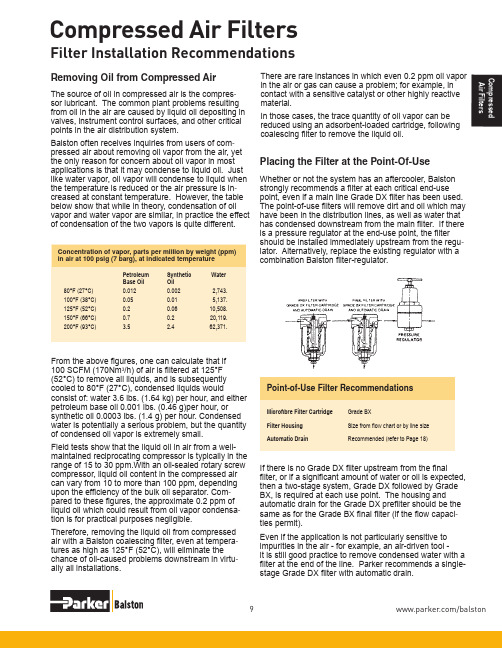
in air at 100 psig (7 barg), at indicated temperature Petroleum Synthetic WaterBase Oil Oil 80°F (27°C) 0.012 0.002 2,743.100°F (38°C) 0.05 0.01 5,137.125°F (52°C) 0.2 0.06 10,508.150°F (66°C) 0.7 0.2 20,119.200°F (93°C)3.52.462,371.Point-of-Use Filter RecommendationsMicrofibre Filter Cartridge Grade BXFilter Housing Size from flow chart or by line size Automatic DrainRecommended (refer to Page 18)combination Balston filter-regulator.From the above figures, one can calculate that if 100 SCFM (170Nm 3/h) of air is filtered at 125°F (52°C) to remove all liquids, and is subsequently cooled to 80°F (27°C), condensed liquids wouldconsist of: water 3.6 lbs. (1.64 kg) per hour, and either petroleum base oil 0.001 lbs. (0.46 g)per hour, or synthetic oil 0.0003 lbs. (1.4 g) per hour. Condensed water is potentially a serious problem, but the quantity of condensed oil vapor is extremely small.Field tests show that the liquid oil in air from a well-maintained reciprocating compressor is typically in the range of 15 to 30 ppm.With an oil-sealed rotary screw compressor, liquid oil content in the compressed air can vary from 10 to more than 100 ppm, depending upon the efficiency of the bulk oil separator. Com -pared to these figures, the approximate 0.2 ppm of liquid oil which could result from oil vapor condensa -If there is no Grade DX filter upstream from the finalfilter, or if a significant amount of water or oil is expected, then a two-stage system, Grade DX followed by Grade BX, is required at each use point. The housing and automatic drain for the Grade DX prefilter should be theCompressed Air Filters/balstonC o m p r e s s e d A i r F i l t e r sProperly specified filters are relatively inexpensive pro -tection for air dryers. Both refrigerated and desiccant dryers benefit from filter protection.Refrigerated Dryers A Grade DX prefilter with automatic drain should beinstalled upstream from a refrigerated dryer to preventoil and condensed water from entering the dryer. Oilentering a dryer coats the cooling coil and reduces its ef -ficiency; condensed water increases the cooling load and reduces dryer capacity. A dryer that was in operation before a Balston filter was installed may already have oil inside it. Therefore a second filter, a Grade BX filter with automatic drain, must be installed downstream from the dryer if oil-free air is required.Desiccant Dryers Desiccant dryers are very sensitive to water and oildroplets. Water can saturate the desiccant and reduceits drying efficiency or even destroy it. Oil can coat the desiccant, rendering it ineffective, or the oil can accumu -late on the desiccant and create a combustion hazardwhen the desiccant is heated for regeneration.For maximum protection of the desiccant dryer, a two-stage filter (Grade DX followed by Grade BX) system with automatic drains should installed upstream from the dryer. To protect downstream delivery points from abra -sive desiccant particles, a high efficiency filter with high solids holding capacity should be installed downstream from the dryer. The Balston Grade DX filter cartridge is recommended for this downstream installation location. (Note: All Balston desiccant dryers are equipped with prefilters and final filters, as recommended above).Membrane DryersMembrane air dryers are sensitive to water and oildroplets. Oil can permanently damage the hollow fiber core. Balston Membrane Air Dryers are assembled with maximum protection, two stage coalescing filters (Grade DX followed by BX) designed to remove all contaminants down to 0.01 microns. Most all other membrane dryers are not assembled with adequate prefiltration protection and should be protected with a two stage Balston Filter System (Grade DX, Grade BX).Using Filters With Air DryersIn a typical compressed air delivery system, a properly specified Balston filter cartridge can be expected to last for one year. The filter cartridge can continue to co -alesce indefinitely, but solids loading in the depth of thecartridge will cause a pressure drop through the housing.The filter should be changed when the pressure drop reaches 10 psi (0.7 barg). At pressure drops higher than 10 psig (0.7 barg), the cartridge will continue to perform at its rated efficiency, but downstream instrumentation may be affected by the pressure drop.To monitor the condition of the filters, install Balston Differential Pressure Indicators (DPI) on the filters or across a multi-filter installation. The DPI gives a vi -sual indication of differential pressure through the filter cartridge. The Balston Differential Pressure Indicatoris factory-installed on 1/4” and larger line size BalstonCompressed Air Filter Assemblies. To use a DPI witha smaller Balston Compressed Air Filter, pressure taps must be provided with “tees” on the line upstream and downstream from the filter. Filter Installation RecommendationsMaintaining The FiltersParker HannifinFiltration and Separation Division 242 Neck Road, Haverhill, MA 01845 1-800-343-4048 or 1-978-858-0505。
OIL-X 高质量压缩空气过滤器系列说明书

OIL-X Die-cast Aluminium Compressed Air FiltersGrade AO General Purpose & Grade AA High Efficiency Coalescing & Dry Particulate Filters (1/4”~ 4”)Coalescing & Dry Particulate FiltersCoalescing filters are the most important items of purification equipment in any compressed air system. They are designed to treat 6 of the 10 main contaminants found in compressed air (aerosols of oil & water and solid particulates such as atmospheric particulate, rust, pipescale and micro-organisms).The origins of modern compressed air filtration can be traced back to domnick hunter in 1963, it was the first company to use microfibre filter media for purification applications, changing the compressed air industry forever. The OIL-X filter range was the first filter range to fully utilise this ground breaking technology and has always been synonymous with high quality compressed air. Now in the 21st century, the OIL-X name remains, but the technology has evolved beyond recognition.Parker domnick hunter OIL-XSince the introduction of the first OIL-X range, Parker domnick hunter has continued to develop both thecompressed air filter and the standards governing compressed air quality.Constantly innovated, OIL-X has become the leading technology for compressed air filtration, providing the exact balance between air quality, energy efficiency andlow lifetime costs.Advantages•Meets or exceeds the requirements for delivered air quality shown in all editions of ISO8573-1, the international standard for compressed air quality •Deep pleated filter element – Filter media is constructed to reduce air flowvelocity and pressure loss whilst providing increased dirt holding capacity, and improved filtration efficiency•Flow management system - Engineered to provide smooth air flow from entry to exit, the filter element design includes a 90-degree elbow, turning vanes and conical flow diffuser to promote a consistent, optimum air flow with minimal pressure loss•Filter Media Optimisation - The flow management system also evenlydistributes compressed air flow throughout the element ensuring optimum filtration performance again with low pressure loss•Parker OIL-X coalescing and dry particulate filters are fully tested – Inaccordance with ISO12500-1 / ISO8573-2 for oil aerosol and ISO8573-4 for particulate•Filtration performance independently validated - by Lloyds Register •Parker OIL-X materials of construction are FDA Title 21 CFR compliant &EX1935/2004 exempt•Air Quality Guarantee - The only filter range to offer a one year air quality guarantee•Housing Guarantee - 10 year guarantee on filter housingsFlow RatesTo correctly select a filter model, the flow rate of the filter must be adjusted for the minimum operating (inlet) pressure at the point of installation.1. O btain the minimum operating (inlet) pressure and maximum compressed air flow rate at the inlet of the filter.2. S elect the correction factor for minimum inlet pressure from the CFMIP table (always round down e.g. for 5.3 bar, use 5 bar correction factor)3. C alculate the minimum filtration capacity. Minimum Filtration Capacity = Compressed Air Flow Rate x CFMIP 4. U sing the minimum filtration capacity, select a filter model from the flow rate tables above (filter selected must have a flow rate equal to or greater than the minimum filtration capacity).Stated flows are for operation at 7 bar (g) (102 psi g) with reference to 20°C, 1 bar (a), 0% relative water vapour pressure.Filtration PerformanceTechnical DataProduct Selection & Correction Factorsand fit an external automatic drain.Grade AO General Purpose Coalescing FilterFiltration PerformanceTechnical DataFlow RatesStated flows are for operation at 7 bar (g) (102 psi g) with reference to 20°C, 1 bar (a), 0% relative water vapour pressure.and fit an external automatic drain.Grade AA High Efficiency Coalescing Filter101000.00010.0010.01OIL-X Grade AO & AA Oil Carryover versus FlowPercentage of Rated FlowO i l C a r r y o v e r (m g /m ³)50750.5125Grade AO (ISO 12500-1 Inlet Challenge 40mg/m³)Grade AA (ISO 12500-1 Inlet Challenge 10mg/m³)Flow RatesTo correctly select a filter model, the flow rate of the filter must be adjusted for the minimum operating (inlet) pressure at the point of installation.1. O btain the minimum operating (inlet) pressure and maximum compressed air flow rate at the inlet of the filter.2. S elect the correction factor for minimum inlet pressure from the CFMIP table (always round down e.g. for 5.3 bar, use 5 bar correction factor)3. C alculate the minimum filtration capacity. Minimum Filtration Capacity = Compressed Air Flow Rate x CFMIP 4. U sing the minimum filtration capacity, select a filter model from the flow rate tables above (filter selected must have a flow rate equal to or greater than the minimum filtration capacity).Stated flows are for operation at 7 bar (g) (102 psi g) with reference to 20°C, 1 bar (a), 0% relative water vapour pressure.Filtration PerformanceProduct Selection & Correction Factorsversion and fit an external automatic drain.Grade AO General Purpose Dry Particulate FilterFiltration PerformanceFlow Rates Stated flows are for operation at 7 bar (g) (102 psi g) with reference to 20°C, 1 bar (a), 0% relative water vapour pressure.and fit an external automatic drain.Grade AA High Efficiency Dry Particulate Filter25%50%75%100%20406080100120Percentage of Rated FlowD i f f e r e n t i a l P r e s s u r e [m b a r ]0140OIL-X Grade AO Coalescing FilterInitial Saturated Differential Pressure (25% - 100% Rated Flow)ISO12500-1 Challenge - 40mg/m³AOPX010AOPX015 & AOPX020AOPX025 & AOPX030AOPX035, AOPX040 & AOPX045AOPX050 & AOPX055OIL-X Grades AO & AA - Differential Pressure Curves25%50%75%100%Percentage of Rated FlowD i f f e r e n t i a l P r e s s u r e [m b a r ]AOPX010AOPX015 & AOPX020AOPX025 & AOPX030AOPX035, AOPX040 & AOPX045AOPX050 & AOPX0550OIL-X Grade AO Dry Particulate FilterInitial Dry Differential Pressure (25% - 100% Rated Flow)1020304050607025%50%75%100%20406080100120OIL-X Grade AA Coalescing FilterInitial Saturated Differential Pressure (25% - 100% Rated Flow)ISO12500-1 Challenge - 10mg/m³Percentage of Rated FlowD i f f e r e n t i a l P r e s s u r e [m b a r ]0140AAPX010AAPX015 & AAPX020AAPX025 & AAPX030AAPX035, AAPX040 & AAPX045AAPX050 & AAPX05525%50%75%100%102030405060OIL-X Grade AA Dry Particulate FilterInitial Dry Differential Pressure (25% - 100% Rated Flow)Percentage of Rated FlowD i f f e r e n t i a l P r e s s u r e [m b a r ]070AAPX010AAPX015 & AAPX020AAPX025 & AAPX030AAPX035, AAPX040 & AAPX045AAPX050 & AAPX055W DDWH©2021 Parker Hannifin Corporation. All rights reserved.PISGSFEOILXPXDCAOAA-00-ENEMEA Product Information Centre Free phone: 00 800 27 27 5374(from AT , BE, CH, CZ, DE, DK, EE, ES, FI, FR, IE, IL, IS, IT , LU, MT , NL, NO, PL, PT , RU, SE, SK, UK, ZA) US Product Information Centre Toll-free number: 1-800-27 27 537 /gsfeEurope, Middle East, AfricaAE – United Arab Emirates, DubaiTel: +971 4 8127100AT – Austria, St. Florian Tel: +43 (0)7224 66201 AZ – Azerbaijan, Baku Tel: +994 50 2233 458BE/NL/LU – Benelux, Hendrik Ido Ambacht Tel: +31 (0)541 585 000BY – Belarus, Minsk Tel: +48 (0)22 573 24 00CH – Switzerland, Etoy Tel: +41 (0)21 821 87 00 CZ – Czech Republic, PragueTel: +420 284 083 111DE – Germany, Kaarst Tel: +49 (0)2131 4016 0DK – Denmark, Ballerup Tel: +45 43 56 04 00ES – Spain, Madrid Tel: +34 902 330 001FI – Finland, Vantaa Tel: +358 (0)20 753 2500FR – France, Contamine s/Arve Tel: +33 (0)4 50 25 80 25GR – GreeceTel: +30 69 44 52 78 25HU – Hungary, Budaörs Tel: +36 23 885 470IE – Ireland, Dublin Tel: +353 (0)1 466 6370IL – IsraelTel: +39 02 45 19 21IT – Italy, Corsico (MI) Tel: +39 02 45 19 21KZ – Kazakhstan, Almaty Tel: +7 7273 561 000NO – Norway, Asker Tel: +47 66 75 34 00PL – Poland, Warsaw Tel: +48 (0)22 573 24 00PT – PortugalTel: +351 22 999 7360RO – Romania, Bucharest Tel: +40 21 252 1382RU – Russia, Moscow Tel: +7 495 645-2156SE – Sweden, Borås Tel: +46 (0)8 59 79 50 00SL – Slovenia, Novo Mesto Tel: +386 7 337 6650TR – Turkey, Istanbul Tel: +90 216 4997081UK – United Kingdom, Warwick Tel: +44 (0)1926 317 878ZA – South Africa, Kempton Park Tel: +27 (0)11 961 0700North AmericaCA – Canada, Milton, Ontario Tel: +1 905 693 3000US – USA, Cleveland Tel: +1 216 896 3000Asia PacificAU – Australia, Castle Hill Tel: +61 (0)2-9634 7777CN – China, Shanghai Tel: +86 21 2899 5000HK – Hong Kong Tel: +852 2428 8008IN – India, MumbaiTel: +91 22 6513 7081-85JP – Japan, Tokyo Tel: +81 (0)3 6408 3901KR – South Korea, Seoul Tel: +82 2 559 0400MY – Malaysia, Shah Alam Tel: +60 3 7849 0800NZ – New Zealand, Mt Wellington Tel: +64 9 574 1744SG – Singapore Tel: +65 6887 6300TH – Thailand, Bangkok Tel: +662 186 7000TW – Taiwan, Taipei Tel: +886 2 2298 8987Parker WorldwideSouth AmericaAR – Argentina, Buenos Aires Tel: +54 3327 44 4129BR – Brazil, Sao Jose dos Campos Tel: +55 080 0727 5374CL – Chile, Santiago Tel: +56 22 303 9640MX – Mexico, Toluca Tel: +52 72 2275 4200。
- 1、下载文档前请自行甄别文档内容的完整性,平台不提供额外的编辑、内容补充、找答案等附加服务。
- 2、"仅部分预览"的文档,不可在线预览部分如存在完整性等问题,可反馈申请退款(可完整预览的文档不适用该条件!)。
- 3、如文档侵犯您的权益,请联系客服反馈,我们会尽快为您处理(人工客服工作时间:9:00-18:30)。
压缩空气精密过滤器
使
用
说
明
书
杭州超滤净设备有限公司
尊敬的用户,为了更好更准确的使用本机器,请您在使用机器前认真阅读本说明书,并严格按照说明书上的使用要求去做。
如果您的机器遇到故障,请认真参照说明书中所列条目对照检修,也可与我们的授权机构或直接拨打售后服务热线8寻求帮助;对您的机器进行及时的保养,将更好的发挥它的性能。
希望本产品在您的工作给您带来便利,谢谢您的支持与合作!
过滤器是利用物理阻隔技术来分离介质中其他成分的一种设备。
空气过滤器是用来过滤空气中固体微粒、水滴及油雾等气溶胶类杂质,使空气获得清净的主要设备。
过滤器结构图
精密过滤器的性能与安装
性能:
安装:
图1、图2所示在一个完整的压缩空气净化系统中,各级过滤器的安装次序。
图3为单支过滤器的标准配置。
1-空压机2-后部冷却器3-贮气罐4-FC级离心式油水分离器
5-冷冻式干燥机6-FT级主管路过滤器
7-FA级微油雾过滤器8-FH级除臭活性炭过滤器
图1 过滤器与冷干机的标准安装次序
1-空压机 2-后部冷却器 3-贮气罐 4-FC 级离心式油水分离器
5-FA 级微油雾过滤器 6-吸干机
7-FT 级主管路过滤器 8-FH 级除臭活性炭过滤器 图2 过滤器与吸干机的标准安装次序
注意事项:
1、过滤器以“先粗后精”原则组合配置,顺序不能颠倒。
2、实际通过过滤器的压缩空气流量、压力及温度不能超过铭牌规定值。
3、安装时须注意分清过滤器的进、出口位置。
4、过滤器安装应对地垂直。
留有一定的离地高度,便于调换滤芯。
B
A
图3 过滤器标准配置图
5、下列情况之一出现时,应当更换滤芯:
a. 过滤效果明显恶化;
b. 压差表示值超过0.07MPa;(注:滤芯初始压降<0.015Mpa)
c. 使用时限:FC、FT、FA为8000h,FH为2000h。
6、不带自动排水器的过滤器,应定时打开球阀排除滤壳积水。
通常每班不少于1—2次。
7、过滤器进气温度不超过66℃。
8、若工作压力低于标准值(0.7MPa)时,过滤器的实际处理能力应按下表进行修正:
常见故障排除
过滤器在使用过程中若出现故障,请按下表找出原因,然后在对症处理。
附:自动排水器
工作原理
图1为常用AD—402型自动排水器。
其动作原理是:当水杯内无气压时,浮子靠自重落下,压块关闭上节流孔,活塞靠弹簧力压下,活塞杆与O形圈脱开,凝结水通过排水口排出。
当水杯内压力大于最低动作压力(0.2MPa)时,活塞受气压力作用,克服弹簧力及摩擦阻力上移,排水口被封闭。
当水杯内水位升高到一定位置,浮子浮力使压块与上节流孔脱离,气压力进入活塞上腔,活塞下移,排水口被打开排水。
水位下落至一定位置,上节流孔又被关闭。
活塞上腔气压通过下节流孔排泄,活塞上移,排水孔再次被关闭,这时水已基本排完。
图1 AD402浮子自动排水器工作原理图
1—主体2—O形圈3—纱网4—压块5—上节流孔6—浮子7—水杯
8—过滤片9—排水口10—O形圈11—排水管12—下节流孔13—活塞
14—活塞密封圈15—弹簧16——控制杆
浮子式自动排水器的特点是没有电气传动和控制部分,使用方便,连接简单,十分适宜用于空气管路设备和过滤器的排水。
维护保养
自动排水器是一个易损零部件,使用不当或长久使用后会出现“长放不关”或“长关不放”两个极端相反的故障。
请注意定时对排水器进行保养并按图2装拆顺序对其不锈钢滤网进行清洗,清水和皂液皆可。