efector500电子压力传感器操作手册
Series EPT-1 电子压力传感器规格与使用说明书

®WIRINGUse 12 AWG wire maximum for electrical connections and 3/16˝ inner diameter rubber or plastic tubing for pneumatic connections. For your convenience we sell 3/16˝ I.D. rubber tubing, part number A-202, and 3/16˝ I.D. flexible vinyl tubing, part number A-220.See Figures 1 and 2 for wiring configurations and Figures 3 through 5for jumper designations.CAUTION•Ensure that the main supply pressure does not exceed 40 psi (276 kPa).•Ensure a minimum of 6 to 10 feet (1.8 to 3.0 m) of tubing between the transducer and the actuator.•For a 24 VAC supply voltage, ensure that the hot and neutral lines are not reversed. If more than one transducer is being powered from the same power supply, the hot and neutral lines should be the same for each transducer.* Do not connect 120 VAC to the electro-pneumatic transducer.Note:The transducer’s gage is for indication only. The transducer measures more precisely than what is displayed on the gage.WIRING DIAGRAMSFigures 1 and 2 illustrate typical wiring diagrams for the electro-pneumatic transducer.CAUTIONThis transducer contains a half-wave rectifier power supply and must not be powered from transformers powering other devices with non-isolated full-wave rectifier power supplies.ADJUSTMENTS - Jumper ConfigurationThe electro-pneumatic transducer is factory configured for a 4-20 mA input. To change the input, adjust the jumper settings as follows (see figures 3, 4 and 5.)©Copyright 2005Dwyer Instruments, Inc.Printed in U.S.A. 12/05FR# R1-443413-00TRANSDUCER OPERATION•Adjust the input signal to obtain a maximum output pressure for the appropriate range.•Ensure that the output is 15 or 20 psi (100 or 138 kPa).•Adjust the input signal to obtain a minimum output pressure.•Ensure that the output is 3 or 0 psi (20 or 0 kPa).CALIBRATIONAll electro-pneumatic transducers are factory calibrated to meet or exceed published specifications. If field adjustment is necessary, follow these instructions.1.Connect air to the Main port (see figure 6).2.Connect an accurate gage to the Branch port using a minimum of 6 to 10 feet (1.8 to3.0 m) of tubing.3.Connect the (+) and (–) terminals to an appropriate power source. The transducer can accept either a 24 VAC or VDC supply voltage. The maximum supply voltage should not exceed 30 VAC/VDC.4.Apply a low input signal to the (–) and (I) terminals (0 VDC or 4 mA).5.Adjust (Z) to obtain the desired low output pressure.6.Apply a high input signal to the (–) and (l) terminals (5/10 VDC or 20 mA).7.Adjust (S) to obtain the desired high output pressure.8.The zero and span controls are slightly interactive, so steps 4 through 7 should be repeated until the transducer is fully cali-brated.MANUAL OPERATION (select models)To manually control the transducer output, you will need to switch SW up for manual mode (see figure 6). Once in manual mode, you can increase or decrease the output by adjusting PB1 and PB2 (see figure 6).MAINTENANCEAfter final installation of the Series EPT-1 Electro-pneumatic Transducer, no routine maintenance is necessary. A periodic check of calibration is recommended following the procedure listed in the CALIBRATION section. Except for this, these transducers are not field serviceable and should be returned, freight prepaid, if repair is needed.Be sure to include a clear description of the problem plus any application information available. Contact customer service to receive a return goods authorization number before shipping.TRAN S DUCER 18-28 VAC TRAN S FORMER + HOT – NEUTRALCONTROLLER + OUTPUT– COMMON S HIELD/GROUNDLEGEND+ = S UPPLY VOLTAGE – = COMMON = INPUT+–TRAN S DUCER 18-28 VAC POWER S UPPLYCONTROLLER + OUTPUT– COMMON S HIELD/GROUNDLEGEND+ = S UPPLY VOLTAGE – = COMMON = INPUT+–+–MAINBRANCHZ S S W PB1PB2+========S UPPLY VOLTAGE COMMON INPUT ZERO S PANUP (MANUAL) DOWN (AUTO)INCREA S E DECREA S E+–Z S S W PB1PB2Figure 1: Wiring the electro-pneumatic transducer with a 24 VAC supply.Figure 2: Wiring the electro-pneumatic transducer with a 24 VDC supply.Figure 3: Jumper settings for electro-pneumatic transducers with 4-20mA input.Figure 4: Jumper settings for electro-pneumatic transducers with 0-5VDC input.Figure 5: Jumper settings for electro-pneumatic transducers with 0-10VDC input.Figure 6: Terminal locations on the electro-pneumatic transducer.。
Fisher 电子压力传感器 IP510 Series 说明书

U Hazardous Location and Intrinsically Safe RatingsU NEMA 4X (IP66)U 0.1% Accuracy TypicalU Closed-Loop Pressure Feedback ControlU Built-In Volume Booster Provides Flow Up to 12 SCFMU Easy Access to Zero and SpanU Damping Pot Prevents Overshoot and HuntingU Low Air ConsumptionU Mount at Any AngleU Compact and LightweightU Virtually No Sensitivity to Supply Pressure ChangesU Removable Orifice for Easy MaintenanceU Buna-N Seals StandardU Fluorocarbon Seals OptionalCurrent to Pressure (I/P) andVoltage to Pressure (E/P) ModelsEP511-X30, shown smaller than actual size.HEAVY-DUTY ELECTROPNEUMATIC CONVERTERS IP510-X27, shown smaller than actual size.IP510 SeriesSPECIFICATIONS Accuracy: Typical: ±0.1% of output span Maximum: ±0.25% of output span Hysteresis: Typical: ±0.01% of output span Maximum: ±0.10% of output span Deadband: No effect The IP510/EP510 Series is a patented family of electro-pneumatic instruments used to reduce a supply pressure to a regulated output pressure that is directly proportional to a 2-wire current or 3-wire voltage input. This design incorporates closed-loop sensing of the output pressure to achieve excellent accuracy and vibration stability. It also features a unique damping circuit that can be adjusted to prevent overshoot and actuator “hunting.” Model selection includes general purpose NEMA 1 (IP00) and watertight/corrosion-resistant NEMA 4X (IP66). All models carry hazardous location and intrinsically safe ratings.Repeatability: Typical: ±0.01% of output span Maximum: ±0.10% of output span Ambient Temperature Effect: Typical: ±0.004% of nominal span per ºF Maximum: ±0.022% of nominal span per ºF Span: Typical: 0.013% of calibrated span per ºF Maximum: 0.022% of calibrated span per ºF Temperature Effect: ≤0.02%/ºF, zero and span effects combinedHEAVY-DUTY ELECTROPNEUMATIC CONVERTERS COIL COIL WIRE DAMPING POTENTIOMETER TERMINAL BLOCK GROUND SCREW NPT ELECTRICAL PORT 1⁄8GAUGE PORT REMOVABLE ORIFICE。
系列壓力感測器操作手冊系列压力传感器操作手册

系列壓力感測器操作手冊注意事項1. 安裝時離開高電壓及具有強高周波雜訊的地方防止干擾。
在以下情況會發生的場所避免使用本機:(a) 灰塵過多及有腐蝕性氣體; (b) 高溼度及高輻射; (c) 震動及衝擊。
2. 本機型僅適用於氣體壓力量測,且應避免使用於腐蝕性氣體,易燃性氣體或有毒氣體的量測。
產品部位名稱1. 壓力值顯示∕參數值內容顯示 6.設定功能鍵2. 設定值顯示∕設定項目顯示 7.向下調整鍵3. 壓力單位顯示 8.電源和輸出信號端子4. 第一/二組數位開關信號輸出指示燈 9.壓力輸入氣孔5. 向上調整鍵選購資訊電氣規格輸入電源電壓範圍12 ~ 24 VDC +/- 10% 無隔離消耗功率40 mA Max.壓力量測壓力型式非腐蝕性氣體,相對式氣壓量測 (gauge type)量測範圍DPB01: -100kPa ~ 100kPa; DPB10: -100kPa ~ 1,000kPa最大耐壓DPB01: 200kPa; DPB10: 1,500kPa量測精度 +/-3%全量程顯示設定顯示雙排LCD顯示,可顯示4位數量測值及3.5位數設定顯示。
顯示週期 100ms、250ms、500ms、1,000ms輸出輸出組數內建兩組NPN或PNP晶體數位輸出晶體輸出最大耐壓30V/100mA,導通殘餘電壓1.5V。
反應時間 2ms、4ms、10ms、30ms、50ms、100ms、250ms、500ms、1,000ms、5,000ms環境溫度操作:0°C ~ +50°C;存放:-20°C ~ +65°C操作環境溼度35% ~ 80% RH(無結露)安裝方式 外觀尺寸面板安裝:需選購配件DPA-PFKit角架安裝:需選購配件DPA-FMKit參數設定操作說明輸出模式設定1. 簡易模式:壓力大於(P + dP) OFF。
(見圖一:簡易模式輸出圖)在量測模式下,按鍵找到,按鍵設定P值。
柳木川电子有限公司EJA系列电子压力传感器用户手册说明书

Y okogawa Electric Corporation IM 01C22A00-12E 2nd EditionIM 01C22A00-12E1.INTRODUCTIONThank you for purchasing the DPharp electronic pressure transmitter.This manual contains important note and handling cautions for the DPharp EJA Series DifferentialPressure/Pressure Transmitters with NEPSI certifica-tion, option code /NS2 and /NF2.Refer to each of the following user’s manuals for standard specifications, functions, handling cautions,and operations, etc.Table 1 List of Individual User’s ManualsEJA110A, EJA120A, and EJA130A IM 01C21B01-01E EJA210A and EJA220A IM 01C21C01-01E EJA310A, EJA430A, and EJA440A IM 01C21D01-01E EJA510A and EJA530A IM 01C21F01-01E EJA110 and EJA120 IM 01C22B01-01E EJA210 and EJA220 IM 01C22C01-01E EJA310 and EJA430 IM 01C22D01-01E EJA118W, EJA118N, and EJA118Y IM 01C22H01-01E EJA438W and EJA438N IM 01C22J01-01E EJA115 IM 01C22K01-01ET01.EPSDocument No.Model2. NEPSI Certificationa.NEPSI Intrinsically Safe TypeCaution for NEPSI Intrinsically safe type.Note 1.Model EJA Series differential, gauge, andabsolute pressure transmitters withoptional code /NS2 are applicable for use in hazardous locations• Applicable Standard: GB3836.1:2000,GB3836.4:2000• Type of Protection and Marking Code: Ex ia IIC T4• Ambient Temperature :–40 to 60°C • Max. Process Temp.: 120°C • Enclosure: IP67Note 2.Entity Parameters• Intrinsically safe ratings are as follows:Maximum Input Voltage (Ui) = 30 V Maximum Input Current (Ii) = 165 mA Maximum Input Power (Pi) = 0.9 WMaximum Internal Capacitance (Ci) = 22.5 nF Maximum Internal Inductance (Li) = 730 µH Maximum Internal Inductance (Li) = 730 µH • Installation RequirementsUo ≤ Ui, Io ≤ Ii, Po ≤ Pi,Co ≥ Ci + Ccable, Lo ≥ Li + Lcable Uo, Io, Po, Co, and Lo are parameters of barrier.Note 3.Installation• In any safety barreir used output current must be limited by a resistor 'R' such that Io=Uo/R.• The safety barrier must be NEPSI certified.• Input voltage of the safety barrier must be less than 250 Vrms/Vdc.• The instrument modification or parts replacement by other than authorized representative of Yokogawa Electric Corporation and will void NEPSI Intrinsically safe certification.• The cable entry devices and blanking elements for type n shall be of a certified type providing a level of ingress protection of at least IP54, suitable for the conditions of use and correctly installed.• Electrical Connection:The type of electrical connection is stamped near the electrical connection port according to the following marking.Note 4. Operation • WARNING:WHEN AMBIENT TEMPERATURE ≥ 55°C,USE THE HEAT-RESISTING CABLES ≥ 90°C.Note 5. Special Conditions for Safe Use • WARNING:IN THE CASE WHERE THE ENCLOSURE OF THE PRESSURE TRANSMITTER IS MADE OF ALUMINUM, IF IT IS MOUNTED IN AN AREA WHERE THE USE OF ZONE 0 IS REQUIRED,IT MUST BE INSTALLED SUCH, THAT, EVEN IN THE EVENT OF RARE INCIDENTS, IGNI-TION SOURCES DUE TO IMPACT AND FRICTION SPARKS ARE EXCLUDED.[Intrinsically Safe]FD No. IM 01C22A00-12E 2nd Edition: June 2011(YK)All Rights Reserved, Copyright © 2007, Yokogawa Electric Corporationb.NEPSI Flameproof TypeCaution for NEPSI flameproof type.Note 1.Model EJA Series differential, gauge, andabsolute pressure transmitters withoptional code /NF2 are applicable for usein hazardous locations:• Applicable Standard: GB3836.1:2000,GB3836.2:2000• Type of Protection and Marking Code:Ex d IIC T6...T4• Enclosure: IP67• Maximum Process Temperature: 120°C (T4),100°C (T5), 85°C (T6)• Ambient Temperature: –40 to 75°C (T4), –40 to80°C (T5), –40 to 75°C (T6)• Supply Voltage: 42 V dc max.• Output Signal: 4 to 20 mA dcNote 2.Wiring• In hazardous locations, the cable entry devices shallbe of a certified flameproof type, suitable for theconditions of use and correctly installed.• Unused apertures shall be closed with suitableflameproof certified blanking elements. (The plugattached is certificated as the flame proof IP67 as apart of this apparatus.)• In case of ANSI 1/2 NPT plug, ANSI hexagonalwrench should be applied to screw in.Note 3. Operation• WARNING:AFTER DE-ENERGIZING, DELAY 10 MINUTESBEFORE OPENING.• WARNING:WHEN AMBIENT TEMPERATURE ≥ 70°C,USE THE HEAT-RESISTING CABLES ≥ 90°C.• Take care not to generate mechanical sparkingwhen accessing to the instrument and peripheraldevices in a hazardous location.Note 4. Maintenance and Repair• The instrument modification or parts replacementby other than authorized representative ofYokogawa Electric Corporation is prohibited andwill void NEPSI Certification.Revision RecordJanuary 20071st edition New PublicationJune 20112nd edition Delete certificaion No.IM 01C22A00-12E。
Bosch SMT500 Leak Detector 漏气检测仪操作指南说明书
2SP01501467 | REV A | 4.2021Bosch Automotive Service Solutions IncSafety PrecautionsBEFORE OPERATING THIS TOOL, ALL OPERATORS SHOULD READ AND UNDERSTAND THIS DOCUMENT AND FOLLOW ALL SAFETY WARNINGS AND INSTRUCTIONS.KEEP THESE INSTRUCTIONS WITH THE TOOL FOR FUTURE REFERENCE. IF YOU HAVE ANY QUESTIONS, CONTACT YOUR BOSCH REPRESENTATIVE OR DISTRIBUTOR.DANGERWhen an engine is operating, keep the service area wellventilated or attach a building exhaust removal system to the engine exhaust system. Engines produce carbon monoxide, an odorless, poisonous gas that causes slower reaction time and can lead to death or serious personal injury.WARNING:• All diagnostic work should be performed with the engine off • Do not leave a vehicle unattended while equipment is connected or operating• Operates on a 12-volt battery: connect to battery (+) and chassis ground (-)• Vapor chamber can become hot. Do not lift or carry by vapor chamber• Do not perform tests near a source of spark of ignition • When working with the fuel system, work in a well-venti-lated area• Always wear the appropriate safety protection• Wear OSHA standard eyewear and protective gloves when using this equipment•When working with hydraulic or fuel lines, be careful that liquids under pressure do not escape and create a dangerous condition. Use adequate ventilation and make sure there are no sparks or possibility of sparks that may ignite any vapor.• Wear an American National Standards Institute (ANSI) Z87.1 approved eye shield when testing or repairing vehicles.• Objects propelled by whirling engine components or pressurized liquids escaping may cause personal injury.•Set the parking brake and block the wheels before test-ing or repairing a vehicle. It is especially important to block the wheels on front-wheel drive vehicles because the parking brake does not hold the drive wheels.• Do not drive the vehicle and operate the software at the same time.• Maintain adequate clearance around moving components or belts during testing.• Moving components and belts can catch loose clothing, body parts, or test equipment and cause serious personal injury or tool damage.•Automotive batteries contain sulfuric acid and produce explosive gases that can result in serious injury due to ignition of gases. Keep lit cigarettes, sparks, flames, and other ignition sources away from the battery at all times.•Refer to the service manual for the vehicle being ser-viced. Adhere to all diagnostic procedures and precau-tions. Failure to do so could result in personal injury or otherwise unneeded repairs.• Use only specially designed replacement parts (brake hoses and lines) for ABS equipped vehicles.• After bleeding the brake system, check the brake pedal for excessive travel or a ”spongy” feel. Bleed again if either condition is present.•When installing transmitting devices (Citizen Band radio, telephone, etc) on ABS-equipped vehicles, do not locate the antenna near the ABS control unit or any other con-trol unit.•This equipment has been tested and found to comply withthe limits for a Class B digital device, pursuant to Part 15 of the FCC Rules. These limits are designed to provide reasonable protection against harmful interference in a residential installation. This equipment generates and radiates radio frequency energy and, if not installed and used in accordance with the instructions, may cause harm-ful interference to radio communications.• Do not operate the tool with a damaged cord or connector. Replace damaged cords and connectors immediately.• Do not expose tool to rain, moisture, or snow.• Verify that cords are located where they will not bestepped on, tripped over, or otherwise become a safety hazard or subjected to damage or stress.•Do not store or leave your tool near a heat source such as a radiator, fireplace, stove, electric heater, or other heat-generating appliance or otherwise expose it to tempera-tures in excess of 60ºC (140ºF). When heated to excessive temperatures, battery cells could explode or vent, causing personal injury or risk of fire.CAUTION:• Do not place the tool on the distributor of a vehicle.Strong electromagnetic interference can damage the tool.• Never disconnect or reconnect any electrical connec-tor while the ignition is on. Powertrain Control Module(PCM) damage may result.SP01501467 | REV A | 4.2021Bosch Automotive Service Solutions Inc3SpecificationsL x W x H 8 in. x 10 in.x 12.5 in. (20 cm x 25 cm x 33 cm)Weight10.3 lb (4.5 kg)Shipping weight 18 lb (8 kg)Power supply12 volts DC; input power supply 11.5–14 VDC Power consumption 8 ampsOutput pressure0.47 PSI / 13.0 in. H20 / 0.032 BAR Operating temperature 30°F to 115°F (-1°C to 46°C)Operating humidity No restrictions Operating altitude No restrictions Vapor output hose 10 ft (3 m)Power supply cables 10 ft (3 m)Operating modes Vapor test cycle/Air only test cycle Pressure SupplyOnboard micro air compressor Micro-compressor duty cycle 100%Housing materialHigh-impact PC/ABS polycarbonate Vapor chamber material Billet aluminum Vapor chamber assembly Bolted Vapor chamber warrantyLifetime4SP01501467 | REV A | 4.2021Bosch Automotive Service Solutions IncReference Guide1. Compound pressure gauge• Indicates amount of pressure or vacuum • Allows for decay/leak down test to confirmrepair is 100% complete 2. Flow meter• Measures leak size as small as 0.010-in.3. Flow control knob• Open flow control valve to allow vapor/pressure into the system• Close flow control valve to lock out systemfor pressure decay testing 4. Reset button• Used for service functions only 5. Air-only test button• Begins 5-minute air-only cycle to testwithout vapor• Blue light indicates onboardmicrocompressor is generating air-only 6. Vapor test button• Begins 5-minute vapor cycle • Red light indicates vapor cycle •Push again to stop testing7. Power indicator light•Green light indicates adequate power8. Fluid fill port• Turn counter clockwise to removedipstick 9. External gas input• 1/4-in. NPT threaded port• Connects external compressed gas(inert gases such as nitrogen or CO2)10. Battery power cables• Connects to 12-Volt DC battery(+) andchassis ground(-)11. Vapor output hoseSP01501467 | REV A | 4.2021Bosch Automotive Service Solutions Inc 5AccessoriesOEM-Approved Vapor-Producing Fluid169500005Vapor-producing fluid will perform over 1,000 typical tests (500+ per bottle)IMPORTANT: Contains no dye/contami-nantsSchrader Valve Removal Tool6522-5EVAP Service Port Adapter6522-4Daylight Spectrum LED Cordless LightSMT-01Bright white beam finds even the tiniest wisps of vapor under the hood or chassisCap Plug Kit6522-6Seals a variety of openings to pressurize system for testingEasy INTAKE™SMT-02Award-winning Easy INTAKE™ is an inflatable block off bladder with a pressurized vapor pass-through that allows technicians to test an entire intake or exhaust system quickly and easily6SP01501467 | REV A | 4.2021Bosch Automotive Service Solutions IncSetupFILL/ADD VAPOR PRODUCING FLUID1. Remove fluid fill dipstick.2. Pour vapor producing fluid into fluid fill portuntil fluid level is near top of the fill line onthe dipstick.3.Replace fluid fill dipstick Notes:• First time fill requires approx. 2 oz (60 ml).• Check fluid level every 75–100 tests.• Never use dyes, solvents, or other contaminantsin intake or exhaust systems. They may coat and/or harm critical sensors and catalysts.• Fill fluid to maximum fill line on dipstick.CONNECT TO POWERThis machine runs on a fully-charged 12-voltbattery.1. Connect red lead (+) to battery’s positiveterminal.2.Connect black lead (-) to chassis ground.Power indicator light:Solid green light Machine has adequatepower Flashing green light Improper power; supplied voltage is too high or toolowNo lightNo power. See TroubleshootingTesting for LeaksTESTING WITH SMOKE1. Connect vapor output hose to system thatis to be tested. See Diagnostics section for more detail.2. Push vapor test button to begin a 5-minutevapor cycleVapor indicator light:Solid red lightVapor is being generated Flashing red lightSee Troubleshooting No lightNo vapor is being generated3. Turn Flow Control Knob counter-clockwiseto release smoke / pressureNote: Flow meter indicates flow and measuresleak size.4. Use provided Halogen Inspection Light tolocate leaks5. Perform repair(s) as neededTESTING WITH AIR-ONLY1. Connect vapor output hose to system thatis to be tested. See Diagnostics section for more detail.2. Push air-only test button to begin a 5-minutevapor cycle.Air-only indicator light:Solid blue light Machine has adequate power 3. Turn flow control knob counter-clockwise torelease pressure.Note: Flow meter indicates flow and measures leak.SP01501467 | REV A | 4.2021Bosch Automotive Service Solutions Inc7Verify RepairsPERFORM DECAY / LEAK DOWN TEST 1. Pressurize the sealed system.2. Lock out system by turning flow control knobclockwise to the fully closed position.OBSERVE PRESSURE GAUGE FOR DECAYPressure holdsNo leaks; repair completePressure decreases Leak(s) exist; repairnecessaryNOTE: Not all systems are designed to be 100%sealed.DiagnosticsIntake System and Vacuum LeaksThis procedure will locate leaks in vacuum lines as well as manifolds, EGR valves, oil seals, gaskets, solenoids, o-rings, ducting, throttle shafts, diaphragms, canisters, and more.Note: For best results, test in a draft-free area.1. Remove the air filter housing from ducting.2. If the vehicle has a round inlet tube from theair filter, place the cone adapter into the duct toward the engine.3. Put the vapor supply hose into cone adapterto introduce vapor into the system.4. Use daylight spectrum LED cordless light tolocate leaks.Alternative method:1. Select an appropriate vacuum line to accessthe vacuum system (i.e. a brake booster supply line before the check valve).2. Seal all system openings.• Air Intake must be sealed to prevent vapor from leaking back through the intake.• To seal the intake, use cap plugs, a latex glove, or plastic wrap around the filter.3. Put vapor output hose into cone adapter tointroduce vapor into the system.4. Use daylight spectrum LED cordless light tolocate leaks.EVAP LeaksLeaks in the EVAP system, or fuel vapor recovery system, are frequently the cause for check engine lights. Using a diagnostic leak detector, these leaks can now be quickly diagnosed and repaired, making them profitable services for repair facilities.1. To access the EVAP service port, remove thegreen cap.2. Remove Schrader valve using the Schradervalve removal tool.Note: Schrader valve has left-handed threads; turn clockwise to remove.3. Connect the EVAP service port adapter tothe service port.4. Use a scan tool to close the vent solenoidto close EVAP system from atmosphere. (If vent solenoid does not close, intermittent solenoid may have failed.)8SP01501467 | REV A | 4.2021Bosch Automotive Service Solutions Inc5. Input vapor into the system through adapter.6. Remove the fuel cap until dense vapor isexiting the filler neck.7. Replace the fuel cap and continue pumpingvapor into the system.8. As the system fills with vapor and the systempressure equalizes, observe the flow meter and pressure gauge.9. When pressure gauge reaches its maximumpressure, the flow meter will indicate leak size.Note: Flow meter will drop to zero if there are no leaks.10. Use the daylight spectrum LED cordless light to inspect under the hood and trace the route of the EVAP system on the undersideof the vehicle for leaks.11. Repair the system as needed.After all repairs have been made, retest the system using the decay or leak down testing method with air only.12. Input air into EVAP system until fullypressurized.13. Lock out system by turning the flow controlknob to the fully closed position.If leaks are repaired properly, system will hold pressure.If pressure decays or leaks exist, repeat above procedures until all repairs are complete.Exhaust LeaksThis test is most effective when exhaust system is cold; thermal expansion may cause small leaks to seal.1. Insert Easy INTAKE™ into the end of thetailpipe. If the vehicle has dual exhaust with cross over system, plug the other tailpipe to seal the system.2. Put vapor output hose into Easy INTAKE™ tointroduce vapor into the system.Note: A hot catalytic converter may consumesome of the smoke.Under-Dashboard LeaksMany vehicles have a common vacuum line, leading from the engine compartment through the firewall, under the dashboard.This line supplies vacuum to climate controlfunctions and other vacuum-operated systems.1. Disconnect the vacuum line, under the hood,at its source.2. Input vapor into the vacuum line.3. Observe the flow meter and pressure gaugewhile changing the climate controls from heat to vent, to defrost, etc.Note: Change in the flow meter or pressure gauge reading will indicate which system is leaking.4. Set the climate control to the leaking system.5. Use the daylight spectrum LED cordless light to locate under-dash leaks.Central locking system leak inspection isperformed in the same manner.Activate control solenoids while introducingvapor into the system.SP01501467 | REV A | 4.2021Bosch Automotive Service Solutions Inc 9MaintenanceCheck Fluid Level1. Remove fluid-fill plug from fluid fill port.2. Pour OEM-approved vapor agent into fluid-fill port until fluid level is near top of the fluid-fill port.3. Replace fluid-fill plug.Check fluid level every 75–100 tests.Clean Flow Meter1. Disconnect air supply and power from themachine.2. Remove the flow meter’s top plug.3. Invert the machine to remove flow meter ball.4. Apply isopropyl/rubbing alcohol to a longcotton swab to clean flow meter tube.5. Use a dry cotton swab to dry flow meter tube.6.Wipe flow meter ball clean with dry cloth.Do not use alcohol / cleaners on flow meter ball.7. Reinstall the flow meter ball and the top plug.Drain Vapor Hose1. Elevate the machine2. Allow the entire vapor hose to hangdownward.3. Place a container beneath the nozzle tocapture fluid.Draining the vapor hose takes approximately 5 minutes.10SP01501467 | REV A | 4.2021Bosch Automotive Service Solutions IncTroubleshootingProblem SolutionNo green light• Check polarity• Ensure 12-volt battery is fully charged • Reconnect power cablesGreen light flashing • Power supply must be between 11.5 and 14 VDC • Connect to a fully charged 12-volt battery • Never use battery charger as power source Amber or red light flashing • Open circuit/internal component • Contact technical supportNo air flow• Open the flow control valve• Ensure hoses are not kinked or pushed into machine Insufficient vapor• Check fluid level• Open the flow control valve• Ensure hoses are not kinked or pushed into machine Flow meter ball sticking • Tap face of flow meter• If problem persists, clean flow meter Gauge bouncing or flow meter bouncingDrain vapor hoseHigh pressure readingEnsure hoses are not kinked or pushed into machine11 NotesSP01501467 | REV A | 4.2021 Bosch Automotive Service Solutions Inc。
电子空气压力仪测量与控制单元操作指南说明书

Operating InstructionsDPG 109Vacuum Measuring AndControl UnitPG0005KJL/E(0508)21.Safety Instructions . . . . . . . . . . . . . . . . . . . . . . . . . . . . . . . . . . . . . . . . . . . . . . .31.1.For Your Orientation. . . . . . . . . . . . . . . . . . . . . . . . . . . . . . . . . . . . . . . . . . . . . . . . . . . . . . . . . 42.Understanding The DPG 109 . . . . . . . . . . . . . . . . . . . . . . . . . . . . . . . . . . . . . . .52.1.Main Features . . . . . . . . . . . . . . . . . . . . . . . . . . . . . . . . . . . . . . . . . . . . . . . . . . . . . . . . . . . . . 5Proper Use. . . . . . . . . . . . . . . . . . . . . . . . . . . . . . . . . . . . . . . . . . . . . . . . . . . . . . . . . . . . . . . . 6Improper Use. . . . . . . . . . . . . . . . . . . . . . . . . . . . . . . . . . . . . . . . . . . . . . . . . . . . . . . . . . . . . . 62.2.Package Contents . . . . . . . . . . . . . . . . . . . . . . . . . . . . . . . . . . . . . . . . . . . . . . . . . . . . . . . . . . 63.Installation . . . . . . . . . . . . . . . . . . . . . . . . . . . . . . . . . . . . . . . . . . . . . . . . . . . . . .73.1.Preparation For Installation . . . . . . . . . . . . . . . . . . . . . . . . . . . . . . . . . . . . . . . . . . . . . . . . . 73.2.Mains Connection. . . . . . . . . . . . . . . . . . . . . . . . . . . . . . . . . . . . . . . . . . . . . . . . . . . . . . . . . . 73.3.Transmitter Connection. . . . . . . . . . . . . . . . . . . . . . . . . . . . . . . . . . . . . . . . . . . . . . . . . . . . . 83.4. PC Connection (RS 232). . . . . . . . . . . . . . . . . . . . . . . . . . . . . . . . . . . . . . . . . . . . . . . . . . . . . 93.5.Relay Output . . . . . . . . . . . . . . . . . . . . . . . . . . . . . . . . . . . . . . . . . . . . . . . . . . . . . . . . . . . . . 104.Operation . . . . . . . . . . . . . . . . . . . . . . . . . . . . . . . . . . . . . . . . . . . . . . . . . . . . . .114.1.First-Time Operation. . . . . . . . . . . . . . . . . . . . . . . . . . . . . . . . . . . . . . . . . . . . . . . . . . . . . . . 114.2.Switching On The Unit . . . . . . . . . . . . . . . . . . . . . . . . . . . . . . . . . . . . . . . . . . . . . . . . . . . . . 124.3.Measuring Mode . . . . . . . . . . . . . . . . . . . . . . . . . . . . . . . . . . . . . . . . . . . . . . . . . . . . . . . . . 124.4.Configuration Mode (Overview Of Menu Options). . . . . . . . . . . . . . . . . . . . . . . . . . . . . 124.5.General Procedure For Parametering. . . . . . . . . . . . . . . . . . . . . . . . . . . . . . . . . . . . . . . . 144.5.1.Menu «PRESSURE». . . . . . . . . . . . . . . . . . . . . . . . . . . . . . . . . . . . . . . . . . . . . . . . . . . . . . . . 154.5.2.Menu «CHANNEL MENU». . . . . . . . . . . . . . . . . . . . . . . . . . . . . . . . . . . . . . . . . . . . . . . . . . 16Gas Type Correction Factor («CHANNEL MENU»). . . . . . . . . . . . . . . . . . . . . . . . . . . . . . 17Retro Adjustment («CHANNEL MENU»). . . . . . . . . . . . . . . . . . . . . . . . . . . . . . . . . . . . . . 18Degassing («CHANNEL MENU»). . . . . . . . . . . . . . . . . . . . . . . . . . . . . . . . . . . . . . . . . . . . 194.5.3.Menu «RELAY MENU». . . . . . . . . . . . . . . . . . . . . . . . . . . . . . . . . . . . . . . . . . . . . . . . . . . . . 204.5.4.Menu «COMMON MENU». . . . . . . . . . . . . . . . . . . . . . . . . . . . . . . . . . . . . . . . . . . . . . . . . . 224.6 Communication Via RS 232 Interface . . . . . . . . . . . . . . . . . . . . . . . . . . . . . . . . . . . . . . . . 235.Error Signals . . . . . . . . . . . . . . . . . . . . . . . . . . . . . . . . . . . . . . . . . . . . . . . . . . .256.Maintenance, Service . . . . . . . . . . . . . . . . . . . . . . . . . . . . . . . . . . . . . . . . . . . .267.Technical Data . . . . . . . . . . . . . . . . . . . . . . . . . . . . . . . . . . . . . . . . . . . . . . . . .277.1.Data Listings. . . . . . . . . . . . . . . . . . . . . . . . . . . . . . . . . . . . . . . . . . . . . . . . . . . . . . . . . . . . . . 277.2.Dimensions Diagram . . . . . . . . . . . . . . . . . . . . . . . . . . . . . . . . . . . . . . . . . . . . . . . . . . . . . . 278.Accessories . . . . . . . . . . . . . . . . . . . . . . . . . . . . . . . . . . . . . . . . . . . . . . . . . . . .289.Supplementary Information . . . . . . . . . . . . . . . . . . . . . . . . . . . . . . . . . . . . . . .28IndexPagePlease note!Current operating instructions are available at 1. Safety Instructions☞Read and follow all the instructions in this manual.☞Inform yourself regarding:–Dangers which can be caused by the unit–Dangers which can be caused by the system☞Observe the safety and accident prevention instructions.☞Check regularly that the safety procedures are being complied with.☞Take into account the prevailing environmental conditions when installing the DPG 109.☞The protection type is IP 20.☞Take account of the relevant instructions when handling the process media and observe the safety procedures.☞Take account of the possible reactions between materials and process media.☞Take account of possible reactions in the process media resulting from the spontaneous warming of the product.☞Do not carry out any unauthorized modifications to or conversions on the unit.☞When returning the unit to the manufacturer please follow the shipping instructions.☞Before beginning work, inform yourself regarding the existence of any possible contamination.☞When handling contaminated parts observe the relevant instructions and follow the safety procedures.☞Ensure that all other users receive the safety instructions.ValidityThese operating instructions describe the installation and operation of the Digital Vacuum Measurement And Control Unit DPG 109 with the part number KTG15010. The part number appears on the rating plate.To ensure the avoidance of possible product identification errors in any correspondence with the Kurt J. Lesker Company please always state the part number appearing on the rating plate.This document is based on the component software version 1.30.Technical modifications reserved.3DPG 1097If the unit is to be fitted into a rack, mains voltage must be supplied via a terminal box.3. Installation0031Kurt J.Lesker Company 1925 Worthington Ave Clairton, PA 15025 。
压力传感器操作指南说明书

压力传感器操作指南说明书操作指南说明书1. 产品概述本操作指南说明书旨在向用户介绍压力传感器的正确操作方法。
压力传感器是一种用于测量物体压力或压力变化的设备,广泛应用于工业领域中的自动化控制系统中。
本说明书将详细介绍压力传感器的各个部件、规格参数以及正确的使用方法。
2. 产品组成压力传感器主要由以下部件组成:- 压力感应器头:用于感知物体的压力,并将其转换为电信号。
- 电路板:将压力感应器头的信号转换为数字信号,通过接口与控制系统进行通信。
- 接口:用于与外部设备连接,传输数字信号。
3. 使用前准备在开始使用压力传感器之前,请确保以下步骤已完成:- 检查传感器的外观是否完好,如有损坏请勿使用。
- 查看产品标识,确认传感器是否适用于您的应用场景。
- 连接传感器到合适的电源,并确保电源电压符合规定。
4. 使用步骤4.1 连接传感器将传感器的接口与控制系统的接口连接,确保连接稳固且无松动。
4.2 设定工作参数根据实际需求,通过控制系统设置传感器的工作参数,如测量范围、刷新频率等。
4.3 校准传感器首次使用传感器或者在长时间使用后,应进行校准操作,以确保精准测量。
具体校准方法请参考附带的校准指南。
4.4 启动传感器通电后,传感器会自动进行初始化,并开始测量工作。
在使用过程中,传感器会持续监测压力变化,并将测量结果通过控制系统进行处理和显示。
4.5 关闭传感器在不使用传感器时,应及时关闭电源,避免长时间不必要的功耗。
5. 注意事项- 请勿在高温、潮湿、腐蚀性环境中使用传感器,以免影响性能和寿命。
- 请勿将压力传感器投掷、撞击或受到过大的力量挤压,以免损坏设备。
- 若传感器长时间不使用,请妥善保管,并放置在干燥、清洁的环境中。
6. 故障排除一旦发现传感器工作异常或显示数值不准确,应立即停止使用,并进行以下检查:- 检查设备连接是否松动或损坏。
- 检查控制系统设置是否正确。
- 尝试重新校准传感器。
若问题仍未解决,请联系售后服务中心或厂家进行进一步的维修和处理。
ifm efector SA5004流速传感器SAD10XDB50KG US-100用户手册说明书

[V] [mA]
[s]
Inputs / outputs Number of inputs and outputs
Outputs Total number of outputs Output signal Number of analog outputs Analog current output Max. load Short-circuit protection Type of short-circuit protection Overload protection
SA5004
Flow sensor
SAD10XDB50KG/US-100
Electrical data Operating voltage Current consumption Protection class Reverse polarity protection Power-on delay time
Reaction times
Flow monitoring
Response time
[s]
0.5; (T09; water; glycol: 0,8 s; air: 7 s; oil: 1,8 s; each T09)
Temperature monitoring Dynamic response T05 / T09 [s]
SA5004
Flow sensor
SAD10XDB50KG/US-100
Temperature monitoring
Temperature drift
Accuracy
[K]
± 0,005 K/°C ± 0,3 / ± 1; (water; Flow velocity: 0,3...3 m/s / air; Flow velocity: > 10 m/s)
ifm PN5002 压力传感器显示器说明书

Delay time programmable dS, dr
[s]
Software / programming
Parameter setting options
Operating conditions
Ambient temperature
[°C]
Storage temperature
[°C]
Protection
PN5002
Pressure sensor with display
PN-100-SBR14-HFPKG/US/ /V
Outputs
Total number of outputs
Output signal
Electrical design
Number of digital outputs
Output function Max. voltage drop switching output DC Permanent current rating of switching output DC Switching frequency DC
1 switching signal
PNP 1
normally open / normally closed; (parameterisable) 2
250 < 170 yes pulsed
0...100 bar 1...100 bar 0.5...99.5 bar
0.5 bar
0...1450 psi 20...1450 psi 10...1440 psi
Mechanical data Weight Materials Materials (wetted parts) Min. pressure cycles Process connection
压力传感器说明书

半导体式压力传感器的结构与动作说明应变片式压力传感器的结构与动作说明●半导体隔膜式压力传感器的结构与动作说明●特点●传感器芯片的结构半导体隔膜式压力传感器采用双重隔膜方式,由直接与测量介质接触的高耐腐蚀性金属隔膜(相当于Hastelloy哈氏合金C-22、SUS316L等)与通过封入的硅油检测压力的硅芯片(硅隔膜)构成。
通过压力导入口直接与测量介质接触的是SUS316L隔膜(或相当于Hastelloy哈氏合金C-22等),介质(空气、水、油及其他)不会浸入其中,能够稳定测量。
[连接螺丝的形状为G3/8时,与配管间采用O型圈密封(氟橡胶)。
]●可以制作能够测量正压、负压、连成压、绝对压力的各种传感器元件●直接接触介质的受压部可以采用相当于Hastelloy哈氏合金C-22、 SUS316L的材料制作,因此,耐腐蚀性能优良●用于检测压力的硅芯片,其隔膜厚度较大,因此,具有优良的耐压性能●半导体隔膜式压力传感器 VESW , VESX , VESY , VESZ , VHR3 , VHG3 , VAR3 , VAG3 , VPRNP , VPNPR , VPNPG , VNF , HS1 , HV1 , AS1 , AV1 , NS1 , NV1 , VESI , VESV , VSW2 , VST 等●应变片式压力传感器 VSD4 , NSMS-A6VB , HSSC , HSSC-A6V , VHS , VHST , HSMC2, HSMC , VPE , VPB , VPRT , VPRTF , VPRQ , VPRQF , 0VPVT , VPVTF , VPVQ , VPVQF , VPRF , VFM , VF , VTRF , VPRF2 , VPRH2 等硅芯片受压部(硅隔膜)与通常的IC制作工艺相同,利用杂质扩散原理形成硅应变片。
当向硅芯片施加压力时,电阻应变片的电阻值会随着其变形而改变,并转换为电信号。
Defender 500系列 说明书

Defender 500系列用户手册简介祝贺你!您选择了Denfender 500系列的具有可靠Drycal技术的一级流量校准器,Defender 510和Defender 520型均能为你提供示数±1%误差的准确度,同时便携耐用的设计方式可使你方便的用于空气采样泵在现场进行校准。
在仪器使用前,我们建议你花一些时间浏览该手册以熟悉你的Defender。
如果你有关于该仪器使用的任何问题,请通过公司网站() 与Bios联系或打电话 973.492.8400向我们高级技术支持工程师咨询。
关于DefenderDefender是一个真正的能够提供即时流量显示的一级标准仪器,精确度为示数的±1%。
它的准确性和快速操作性使它成为一个极好的校准工具,能以负压或正压应用模式将设定的流量快速准确的显示在空气采样泵上。
Defender 520型仪器的可选功能更多,它在气路系统使用综合的温度和压力传感器以记录校准期间的周围环境。
作为一个理想的“三合一”校准器,Defender 520型能提供扩展跟踪-流速、温度和压力-而不需要额外的仪器。
Defender是由一个内置的铅蓄电池提供能量(仪器中包括),这种电池没有记忆效应,即使仪器在使用时也可以连续充电,Defender的特点是具有on/off控制按钮,液晶显示屏和方便的键盘控制。
通过触摸键盘上的右、左、上和下箭头控制在不同的命令屏上操作Defender标配有以下配件:交流适配器/充电器Bios Optimizer 软件安装光盘电脑串口数据线塑料的泄漏测试帽(2);在泄漏测试时使用校准证书使用手册软质包装盒子或硬质包装盒,可从Bios或Bios经销商处购买Defender操作开始使用尽管Defender的电池出厂时已经充电,但我们建议你第一次使用时应使用交流电源适配器/充电器将新电池充满电,初次充电时间约8小时。
初次充电后,你可以继续将它连在充电器上给Defender充电,另外还需注意应每隔三个月给Defender至少充电一次以延长电池寿命。
ifm efector PN5001 压力传感器与显示器说明书
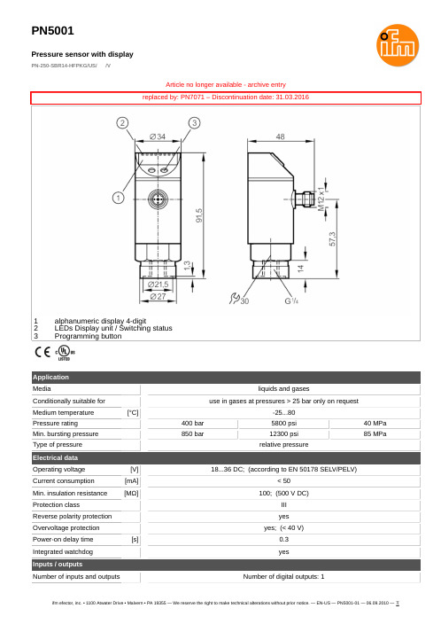
ifm efector, inc. • 1100 Atwater Drive • Malvern • PA 19355 — We reserve the right to make technical alterations without prior notice. — EN-US — PN5001-01 — 06.09.2010 —
< ± 0,25 < ± 0,05; (per 6 months)
0,2; (0...80 °C)
0,2; (0...80 °C)
0; 0,2...50
hysteresis / window; normally open / closed; switch-on/switch-off delay; Damping; Display unit
PN5001
Pressure sensor with display
PN-250-SBR14-HFPKG/US/ /V
Outputs
Total number of outputs
Output signal
Electrical design
Number of digital outputs
Output function Max. voltage drop switching output DC Permanent current rating of switching output DC Switching frequency DC
stainless steel (1.4305 / 303); ceramics; FKM
100 million
threaded connection G 1/4 Internal thread
压力传感器使用方法说明书

压力传感器使用方法说明书一、产品概述压力传感器是一种用于检测、测量和监测液体或气体压力的设备。
本使用方法说明书旨在帮助用户正确使用压力传感器,并有效解决在使用过程中可能遇到的问题。
二、技术参数1. 测量范围:(填入测量范围,如0-10MPa)2. 精度:(填入精度,如±1%)3. 输出信号:(填入输出信号类型,如4-20mA)4. 工作温度范围:(填入工作温度范围,如-20℃至80℃)5. 供电电源:(填入供电电源类型及电压范围,如12-36V DC)三、安装步骤1. 准备工作:在进行安装之前,确认已关闭所有相关设备的电源,并确保操作环境安全。
2. 安装位置:选择合适的安装位置,并确保传感器与被测介质充分接触。
在安装前,清洁被测介质并移除其中的杂质。
3. 连接电源:将传感器的电源线连接至供电电源,并确保极性正确连接。
4. 连接输出信号:根据使用要求,连接传感器的输出信号线至相应的接收设备。
5. 安装固定件:根据需要,使用合适的固定件将传感器牢固地固定在安装位置上。
6. 校准:根据需要进行传感器的校准,以确保测量结果的准确性。
7. 检查:完成安装后,检查所有连接是否牢固,并确保无泄漏现象。
四、使用注意事项1. 防尘防水:确保传感器的工作环境干燥,并避免灰尘、水分等杂质进入传感器内部,以免影响正常工作。
2. 温度限制:请在传感器允许的工作温度范围内使用,并避免超温使用,以免损坏设备。
3. 避免过载:确保被测介质的压力不超过传感器的测量范围上限,避免产生过载现象。
4. 避免撞击:使用过程中,请避免传感器受到重物撞击或挤压,以免损坏设备。
5. 维护保养:定期检查传感器的工作状态,并根据需要进行清洁和保养。
五、故障排除1. 传感器不工作:检查电源连接是否正确,并确认供电电源是否正常工作。
2. 输出信号异常:检查输出信号线是否连接正确,并确保接收设备的正常工作。
3. 测量结果不准确:进行传感器校准并检查被测介质的状态是否正常。
压力传感器使用说明书

压力传感器使用说明书1211131000/100110141100/11019158167176185194203212221一.仪表选型注1:标准型:仪表出厂前具有继电器输出和电压脉冲输出。
注2:如果仪表选串行通讯口,报警只能选该型号。
二.接线图电源报警2(-)AC90-260V (+)RS484报警3(-)通讯SSR 输出-(+)(D2)24V/20mA +电流互感器输入继电器AC5A 4-20mA 输出+报警1或热电偶PT100第二输出(带PD )安装尺寸(面板安装)1000/10011100/110150145+0.692+0.845+0.692+0.892+0.845+0.6深100mm深100mm深105mm注:为确保安装正确,请参阅英文版手册中的注意事项和警告。
三.功能说明1)输入种类热电偶:K、J、N、S、R、T热电阻:PT100电压:0-50mv,10-50mv电流:0-20mA,4-20mA,0-10mA(电流输入需在输入端并接2.5Ω或5Ω精密电阻)电流互感器输入2)输出输出1:继电器:端子额定电流5A/220VacSSR:24V/20mA电压脉冲DC输出:4-20mA输出2:用报警输出1,通过软件组态改为PD控制功能3)报警功能报警1可以带PD控制,触点电流5A报警2和3触点为常开,可以通过内部跳线改为常闭触点容量为3A/220Vac4)数字通讯(电流环/RS485)如果仪表有1200波特率无源电流环接口,接收二极管在端子8(RX+)和端子9(RX-)传输晶体管端子10(TX+)和(TX-)标准配置(并联到串行口)联接到二极管阻值为1千欧,集电极电阻为100Ω对串联连接,接到二极管阻值为100欧若配置为4线制RS485(1200波特率),输入端为8(RX+)和9(RX-)传输为10(TX+)和11(TX-)[参阅硬件组态]四.显示面板和按键说明A:显示测量值B:显示设定值1)显示过程设定值2)当AL1,AL2,AL3/HB灯闪烁时,设定报警值显示3)当字母“P”前面显示[0-99%]显示主输出功率4)可显示组态参数F:主输出灯,当第一输出动作时该灯亮G:报警输出指示C :功能键“F ”1)F 键用来选择设定值或报警值以便读取和修改设定值,如果未按住F 键,10秒钟后,修改值将自动存贮,同时返回显示过程设定值。
压力传感器的使用指南说明书

压力传感器的使用指南说明书压力传感器使用指南说明书1. 引言压力传感器是一种用于测量压力变化并将其转换为电信号的设备。
本说明书旨在向用户提供关于压力传感器的详细信息以及正确使用和维护该设备的指南。
2. 压力传感器的工作原理压力传感器基于压电效应或德式效应,通过测量压力对感应电极产生的变化电荷或电阻进行压力测量。
该设备对于各种应用领域,如工业自动化、汽车工程、医疗监测等起着至关重要的作用。
3. 适用范围本款压力传感器适用于各种气体或液体介质的压力测量。
请在使用前仔细查阅技术规格表,确保其适用于目标应用环境的压力范围和介质。
4. 安装要求4.1 安装位置:为确保准确测量压力,请将传感器安装在位于压力变化区域的合适位置。
避免在振动、温度变化较大或受到冲击的环境中直接安装。
4.2 连接管路:根据应用需求,选择合适的管路和连接接头,并确保其与传感器连接紧固可靠,避免压力泄漏。
5. 连接和电气接线5.1 连接方式:根据用户需求,可选择扁平电缆连接或引线连接。
5.2 接线要求:用户在连接电源和信号输出时,请遵循正确的极性连接规则,确保传感器能够正常工作。
6. 使用注意事项6.1 温度限制:请确保传感器在规定的温度范围内工作,避免超出温度范围,以免影响设备的性能和寿命。
6.2 防尘与防水:传感器防护等级应根据实际需求选择,以确保设备在尘土、湿气等恶劣环境下的正常运行。
6.3 电磁干扰:请避免将传感器安装在具有强电磁辐射的设备附近,以免影响传感器的准确性。
6.4 震动与冲击:传感器对于颠簸、震动和冲击很敏感,请注意将其安装在稳定的位置,并采取适当的防护措施。
6.5 供电电压:在使用过程中,请确保传感器的电源电压与规定的供电电压相匹配,以免引起设备损坏。
7. 校准和维护7.1 校准:为保证测量的准确性和稳定性,建议定期对传感器进行校准。
请参考附带的校准操作手册执行校准。
7.2 维护:传感器在使用过程中需要定期清洁和维护。
压力传感器的操作介绍

压力传感器的操作介绍1.安装传感器:首先要选择合适的传感器型号和规格,根据具体的应用需求,确定传感器的测量范围、输出信号类型和工作环境等参数。
然后,按照传感器的安装指南,将传感器正确安装到被测对象上。
注意传感器与被测对象之间的接触面要充分密封,以保证压力信号的准确性。
2.连接信号线:将传感器与读取设备连接起来。
通常情况下,传感器会有两根信号线,一个是电源线,用于提供电源给传感器;另一个是信号线,用于传输传感器测得的压力信号。
根据传感器的电气接口,将信号线正确连接到读取设备上。
3.设置参数:根据具体的应用需求,有些压力传感器可以进行参数的设置,如测量范围的调整、输出信号的标定等。
通过连接读取设备,可以进入传感器的设置界面,根据设备的说明书进行相应的参数设置。
4.热补偿(可选):有些高精度的压力传感器需要进行热补偿操作,以消除温度对传感器的影响。
热补偿是通过连接温度传感器,测量当前环境温度,并经过计算得到补偿系数,再根据补偿系数去修正压力传感器输出的压力值。
5.读取数据:当传感器已经连接好并设置完毕,可以通过读取设备来实时读取传感器输出的压力信号。
根据具体的读取设备,可以通过仪表、计算机等设备来查看压力值的变化情况。
6.数据分析和控制:读取到的压力数据可以进行分析,了解被测对象的压力变化情况。
同时,可以通过控制设备,对被测对象的压力进行控制,以实现特定的操作要求。
7.维护保养:定期对压力传感器进行检查和维护,确保传感器的正常工作。
可以清洁传感器表面,防止杂质进入影响测量精度,也可以定期校准传感器,保证测量准确性。
总结:以上是压力传感器的操作介绍。
通过正确安装、连接信号线、设置参数、热补偿、数据读取、数据分析和控制、维护保养等步骤,可以正确使用压力传感器,并得到准确的压力测量结果。
压力传感器在工业控制和科学研究中有着广泛的应用。
AVENTICS Pressure sensor, Series PE5 压力传感器说明书
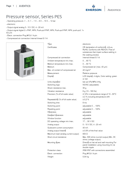
Pressure sensor, Series PE5- Operating pressure -1 ... 0 -1 ... 1 0 ... 6 0 ... 10 0 ... 12 bar- electronic- Output signal analog 0 - 10 V DC, 4 - 20 mA- Output signal digital 2 x PNP, NPN, Push-pull PNP, NPN, Push-pull PNP, NPN, push-pull, 1xIO-Link- Electr. connection Plug M12x1 4-pin- Compressed air connection Internal thread G 1/4Type electronicCertificates CE declaration of conformity, cULus,RoHS, Conforms with REACH, Free ofsubstances that impair surface wetting inthe coating processCompressed air connection Internal thread G 1/4Ambient temperature min./max.0 ... 60 °CMedium temperature min./max.0 ... 60 °CMedium Compressed air (max. 40 μm)Max. oil content of compressed air40 mg/m³Measurement Relative pressureDisplay LCD display, 4 digits, Color setting: greenor redUnits displayed bar psi kPa MPa inHgSwitching logic NO/NC (adjustable)Shock resistance max.30 gVibration resistance 5 g (10 - 150 Hz)Precision (% of full scale value)±1.5% in temperature range of 10 - 30°C± 2 % including temperature driftRepeatability (% of full scale value)± 0,2 %Switching time 5 msSwitching point adjustable 0 ... 100%Resetting point adjustable 0 ... 100%Hysteresis adjustableDelayed hysteresis adjustableWindow function adjustableDC operating voltage min./max.17 ... 30 V DCAnalog output0 - 10 V DC, 4 - 20 mAQuiescent current consumption40 mAAnalog output linearity± 0.5% of the final valueMaximum load (analog current output)600 ΩShort circuit resistance Max. 600 ohms (current output) Min. 3Kohms (voltage output)Mounting types Directly on hat rail and wall mounting Forpanel installation using mounting kit viadouble nippleProtection class IP65 IP67 with connections assembledElectr. connection Plug M12x1 4-pinWeight0,04 kgOutput signal0 - 10 V DC-4 ... 20 mA1) The IO-Link device description (IODD) for the PE5 pressure sensor is available for download in the Media Centre.1) M12x1 electrical connection2) Mounting for hat rail and wall mounting3) Alternative pressure connection (G1/4) closed with plug4) Pressure connection G1/41) M12x1 electrical connection2) Mounting for hat rail and wall mounting3) Alternative pressure connection (G1/4) closed with plug4) Pressure connection, tubing Ø 4 mm1) LCD display2) Control panel with 3 buttonsH: HysteresisSP = switching pointRP = resetting pointOut (NC): switch output, break contact Out (NO): switch output, make contactH: HysteresisSP = switching pointRP = resetting pointOut (NC): switch output, break contactOut (NO): switch output, make contactdS: switching delaydR = reset delay1) period of pressure over the switching point dS: pressure sensor does not switch2) Period of pressure over the switching point > dS: pressure sensor switches3) Period of pressure under the resetting point > dR: pressure sensor switchesFH: pressure band, upper valueFL: pressure band, lower valueOut (NC): switch output, break contact Out (NO): switch output, make contact1) Internally stored parameter2) Adjustable parameter3) Output valueRL = storable postionRL = storable postionAllocation operational voltage + UBswitch output Out2, analog: A or V, digital: PNP, NPN, push-pull0 Vswitch output Out1, digital: PNP, NPN, push-pullAllocation Supply Voltage Switch output PNP/NPN/push-pull, switchable0 VSwitch output PNP/NPN/push-pull/leakage mode, digital switch input PNPAnalog output ( 0 to 10 V DC, 4 to 20 mA)Your local contact:/contactus/EmersonAutomationSolutions/company/Emerson-Automation-SolutionsAn example configuration is depicted on the title page. The delivered product may thus vary from that in the illustration. Subject to change. This Document, as well as the data, specifications and other information set forth in it, are the exclusive property of AVENTICS GmbH. It may not be reproduced or given to third parties without its consent. Only use the AVENTICS products shown in industrial applications. Read the product documentation completely and carefully before using the product. Observe the applicable regulations and laws of the respective country. When integrating the product into applications, note the system manufacturer's specifications for safe use of the product. The data specified only serve to describe the product. No statements concerning a certain condition or suitability for a certain application can be derived from our information.The information given does not release the user from the obligation of own judgement and verification. It must be remembered that the products aresubject to a natural process of wear and aging.of the Emerson family of companies. All other marks are the property of their respective owners. © 2020 Emerson Electric Co.All rights reserved.2020-12。
感应式压力传感器P500的产品说明说明书

| P500PRESSURE SENSOR DescriptionFeatures• Small Size (3/4” Hex)• External Hex for Easy Installation • Linear Amplified Output • Temperature Compensated • Superior Long-Term Stability • Low Power Consumption• Minimum Life Expectancy: Ten Million CyclesThe P500 incorporates Kavlico’s 4th generation ceramic capacitive sense element with the latest state of the art proprietary ASIC. Available in brass or stainless steel housings, this multi-purpose sensor is rugged by design. Highly reliable, the P500 is ideal for measuring a broad range of process media including hydrocarbon based fluids, air, and gases. The P500 package has a built-in Metri-Pack 150 series sealed electrical connector and is available with popular pressure connection thread options. The sensor is offered with seal materials suitable for diverse applications. Standard pressure ranges are available in PSI or Bar.Applications• Compressors • Process Controls• Instruments & Test Equipment • Sterilizers • Air Pressure• Oil & Fuel Pressure • Coolant Pressure• Agricultural Equipment• CNG & Natural Gas EnginesSPECIFICATIONSTECHNICAL SPECIFICATIONSPressure RangesPhysicalPerformanceElectricalPART NUMBER DESIGATION: P500-300-S-E 4 AVoutputN/CVsupplyGNDVENT HOLE (GAUGE)USE STANDARD OPENEND WRENCH OR SPECIALIZED SOCKET WRENCH ONLY19.1818.69.755.736HEXDATE CODE EXAMPLE: L0515UL LOGO (PRESSURE DEPENDENT)KAVLICO PART #(SEE EXAMPLE)PERMANENTLY IDENTIFY X X X X XDATE CODE11P500-XXX-X-X4XSHOWN19.09 1.575 MAX.752405.59.220Dimensions in mm [Inch]DIMENSIONSPressure Sensor with Electrical ConnectionPressure Connections and Recommended Installation Torque1/4 - 18 NPT 1/8 - 27 NPT Stud EndDIN 3852-B-G1/4External External External 25 Nm20 Nm20 NmTapped Hole DIN 3852-Y-G1/43/8-24 UNF-2A PER SAE J 1926/23/8-24 UNF-2B PER SAE J 1926/1Internal External Internal 15 Nm22 Nm22 NmPage 4CONTACT USAmericas+1 (800) 350 2727***************************************Europe, Middle East & Africa +359 (2) 809 1826****************************Asia Pacific*************************.com China +86 (21) 2306 1500Japan +81 (45) 277 7117Korea +82 (31) 601 2004India +91 (80) 67920890Rest of Asia +886 (2) 27602006 ext 2808Sensata Technologies, Inc. (“Sensata”) data sheets are solely intended to assist designers (“Buyers”) who are developing systems that incorporate Sensata products (also referred to herein as “components”). Buyer understands and agrees that Buyer remains responsible for using its independent analysis, evaluation and judgment in designing Buyer’s systems and products. Sensata data sheets have been created using standard laboratory conditions and engineering practices. Sensata has not conducted any testing other than that specifically described in the published documentation for a particular data sheet. Sensata may make corrections, enhancements, improvements and other changes to its data sheets or components without notice.Buyers are authorized to use Sensata data sheets with the Sensata component(s) identified in each particular data sheet. HOWEVER, NO OTHER LICENSE, EXPRESS OR IMPLIED, BY ESTOPPEL OR OTHERWISE TO ANY OTHER SENSATA INTELLECTUAL PROPERTY RIGHT, AND NO LICENSE TO ANY THIRD PARTY TECHNOLOGY OR INTELLECTUAL PROPERTY RIGHT, IS GRANTED HEREIN. SENSATA DATA SHEETS ARE PROVIDED “AS IS”. SENSATA MAKES NO WARRANTIES OR REPRESENTATIONS WITH REGARD TO THE DATA SHEETS OR USE OF THE DATA SHEETS, EXPRESS, IMPLIED OR STATUTORY, INCLUDING ACCURACY OR COMPLETENESS. SENSATA DISCLAIMS ANY WARRANTY OF TITLE AND ANY IMPLIED WARRANTIES OF MERCHANTABILITY, FITNESS FOR A PARTICULAR PURPOSE, QUIET ENJOYMENT, QUIET POSSESSION, AND NON-INFRINGEMENT OF ANY THIRD PARTY INTELLECTUAL PROPERTY RIGHTS WITH REGARD TO SENSATA DATA SHEETS OR USE THEREOF.All products are sold subject to Sensata’s terms and conditions of sale supplied at SENSATA ASSUMES NO LIABILITY FOR APPLICATIONS ASSISTANCE OR THE DESIGN OF BUYERS’ PRODUCTS. BUYER ACKNOWLEDGES AND AGREES THAT IT IS SOLELY RESPONSIBLE FOR COMPLIANCE WITH ALL LEGAL, REGULATORY AND SAFETY-RELATED REQUIREMENTS CONCERNING ITS PRODUCTS, AND ANY USE OF SENSATA COMPONENTS IN ITS APPLICATIONS, NOTWITHSTANDING ANY APPLICATIONS-RELATED INFORMATION ORDERING OPTIONSP500 Sensor, 0 - 16 Bar Absolute, Fluorosilicone Seal Material, 1/4 - 18 NPTA: With Mating Connector, w/12”, 18 AWG Leads C: Without Mating ConnectorAGENCY APPROVALS & CERTIFICATIONSEN 61326-1, 2006IEC 61000-4-2, 2001IEC 61000-4-3, 2006IEC 61000-4-8, 20012002/95/EC RoHS Directive File # SA10552。
- 1、下载文档前请自行甄别文档内容的完整性,平台不提供额外的编辑、内容补充、找答案等附加服务。
- 2、"仅部分预览"的文档,不可在线预览部分如存在完整性等问题,可反馈申请退款(可完整预览的文档不适用该条件!)。
- 3、如文档侵犯您的权益,请联系客服反馈,我们会尽快为您处理(人工客服工作时间:9:00-18:30)。
可编辑efector 500 电子压力传感器操作说明1 显示屏菜单结构 P.3 ---------------------------------------------1 2 编程 P.4 ---------------------------------------------------------1 3 安全提示 ---------------------------------------------------------1 4 控制和显示说明--------------------------------------------------1 5 功能及特性-------------------------------------------------------1 6 操作模式 ---------------------------------------------------------3 7 安装 --------------------------------------------------------------3 8 电气连接 ---------------------------------------------------------4 9 编程 --------------------------------------------------------------4 10安装和装配/操作 ------------------------------------------------5 11技术信息/功能/参数 --------------------------------------------6精品可编辑1 显示屏菜单结构 P.3(图)2 编程 P.41. 选择参数; 2. 设定数值*; 3. 参数值确定。
* 当参数调至最大设定值,继续调整参数值将从最小的设定值重新开始循环。
在设置开 关点(SPx,rPx)或模拟输出信号(ASP,AEP)的限制之前选定显示单位,这将避免 单位转换中舍入误差的发生,得到更精确的设定值。
3 安全提示 安装之前请阅读产品说明; 请检查该产品是否适合你的使用; 用户如未遵循本手册的操作说明或技术数据进行操作,可能发生人身伤害或财产损失; 在所有应用中,请检查本产品的材料(参看技术数据)是否适用于所测量的物质。
4 控制和显示说明(图)P.20 ① 7 段码数字显示屏 ② 2×红色发光二极管LED ③ 模式/输入( Mode/Enter )按 键 ④ 设定(Set)按键系统压力显示,参数和参数值显示 状态转换提示,如输出Ⅰ/Ⅱ转换相应灯发光 选择参数和确定参数值设定参数值(按下该按键数值增加,按住按键数值连续增加)精品可编辑5 功能及特性 该压力传感器检测系统压力; 显示屏指示当前系统压力; 通过输出设置产生 2 个输出信号。
输出 1输出 2模拟输出I:4…20mA(仅输出 2 显示)U:0…10V转换函数 (在输出 1 和输出 2 中函数可以分别选取)滞后函数/N.O.(Hno) 滞后函数/N.C.(Hnc) 窗口函数/N.O.(Fno) 窗口函数/N.C.(Fnc)输出极性 (同时应用于 2 个输出)正转换(p-switching,PnP) 负转换(n-switching,nPn)5.1 程序设定通过设定各类参数,所测信号的赋值是不同的,可应用于各自不同的应用。
(见 9、11.1 节)5.2 EHEDG 3A部件已通过 EHEDG 和 3A 认证。
5.3 应用型号 PF2053 PF2054 PF2056 PF2057bar PSI MPabar PSI kPabar PSI kPa mbar PSI kPa测量范围 -1.0…25 -15…363 -0.1…2.5-0.5…10 -7…145 -50…1 000-0.13…2.501) -1.8…36.3 -13…250 -50…1 000 -0.7…14.5 -5.0…100允许过载压力爆破压力10035014505 070103550 725 5 000(5MPa)150 2 175 15 000 (15MPa)20502907252 000(2MPa) 5 000(5MPa)10 000(10bar) 30 000(30bar)1454501 000(1MPa) 3 000(3MPa)精品可编辑1)如显示到负值小数点后两位,小数点前的 0 不会显示。
如:-0.05 显示为-.05 不同显示单位的标示方式封装于设备中,选取传感器上各自的标示或填入空白的标示。
勿使静态或动态的过压超过给定的过载压力。
任何高于爆破压力的瞬时压力都会损伤设备(损伤危险)!6 操作模式6.1 运行模式(Run mode)正常操作模式。
当所需电压已经提供时,设备处于运行模式。
根据设定参数监视并产生输出信号。
显示屏指示当前系统压力(见 11.1 节)。
红色发光二极管指示输出的状态切换。
6.2 显示模式(Display mode)参数指示和参数值设定。
按下 Mode/Enter 按键,设备进入可以读取参数值的显示模式。
此时内部的传感、处 理和输出功能仍然继续进行。
用 Mode/Enter 按键选取需要设定的参数; 按下 Set 按键,相应的参数值会显示 15 秒。
再经过 15 秒设备返回运行模式。
6.3 编程模式(Programming mode)参数值的设定。
看见参数值时,按住 Set 键 5 秒以上,设备进入编程模式。
Set 键改变参数值,按下 Mode/Enter 键确定新的参数值。
该模式期间设备仍将按之前的参数继续进行感应、处理 和输出计算,直到新的参数值确定。
如果 15 秒内未按下任何按键,设备将返回运行模式。
7 安装装配和拆除传感器时,确定系统没有承受压力。
精品可编辑7.1 工艺适配器该设备可采用单独购买的 ifm 适配器作为其附件。
首先将适配器(C)安装到传感器上,然后传感器+适配器通过螺母、钳位法兰或其他类 似原件(B)装上工艺连接件。
(图)P.23如果使用焊接适配器:首先焊接适配器,然后安装传感器。
7.2 适配器的安装如果固定件(B)不能通过传感器顶部套入:装配适配器前先将固定件套入传感器底部。
传感器和设配器只能进行一次安装。
步骤 1:用提供润滑粘贴剂涂抹于传感器和适配器的螺纹和密封切面上。
润滑粘贴剂符 合食品级要求(USDA-H1 84-201)。
确定 O 型环(D)安装正确。
(图)P.23 步骤 2:将传感器装入适配器。
避免密封页面的机械损伤。
(图)P.23 步骤 3:将传感器和适配器钳入箝位(紧固)装置(E)。
不要损伤密封斜面(F)。
用扳 手紧固传感器直到感觉不能拧动为至。
(图)P.24如果继续拧紧,可能对密封造成损伤。
8 电气连接该单元必须由电工连接。
安装中必须遵守电气设备安装相关的国内和国际规定。
电压提供满足 EN50178,SELV,PELV。
连接设备前切断电源。
配线:2×正极 (图)P.24 1×正极/1×模拟 (图)P.24 连接插槽(传感器) (图)P.242×负极 (图)P.24 1×负极/1×模拟 (图)P.24 Ifm 插槽内芯颜色: 1=BN(褐色)精品可编辑2=WH(白色) 3=BU(蓝色) 4=BK(黑色)9 编程可调参数(见 11.1 节)菜单结构(见 1 节)1 按下 Mode/Enter 键几次,直到相应的参数显示 (图)P.25按住 Set 键,当前的参数值闪烁显示 5 秒,然后增加数值*(按下按键数值2 增加,持续按住按键数值连续增加)(图)P.25按下 Mode/Enter 键(确认)。
参数类型再次显示,参数值已经改为设定3值(图)P.254 更改其他参数: 返回步骤 1结束编程: 等待 15 秒,或按 Mode/Enter 键直 到显示当前测量值。
*当参数调至最大设定值,继续调整参数值将从最小的设定值重新开始循环。
在设置开关点(SPx,rPx)或模拟输出信号(ASP,AEP)的限制之前选定显示单位,这将避免单位转换中舍入误差的发生,得到更精确的设定值。
9.1 超时退出如果设定过程中有 15 秒内未按下任何按键,将返回运行模式,参数值不发生变化。
9.2 快速编程/连续编程设定的参数由编程/显示单元 PP2000 存储,然后可传给其他单元。
编程说明见编程设备的操作指导。
9.3 锁定/解锁为防止对设定参数的意外调整,设备可电子锁定:按住两个按键 10 秒(设备必须处于 运行模式),锁定显示会弹出(锁定/解锁确定)。
出厂时设备处于解锁状态。
当设备处于锁定状态下,任何试图改变参数值的操作都会在显示屏上出现 Loc。
精品可编辑10 安装和装配/操作装配、配线和检查后,确认设备是否正常运行。
10.1 运行器件的故障显示OL超负荷 overload=(高于传感器的测量范围)UL负荷不足 underload=(低于传感器的测量范围)SC 1 (闪烁)=转换输出 1 短路SC 2 (闪烁)=转换输出 2 短路SC(闪烁)=两路转换输出都发生短路短路的输出会被切断。
10.2 中止保护级别传感器避免在极端恶劣的环境下使用(防护等级 IP67)。
使用专门的附件(产品号 E30043)可以提高防护等级。
10.3 过滤盖清洗如果传感器过滤盖由于粘性物和残余物媒体阻塞(引起测量精度的下降),需要进行清 洗。
(图)P.26 拧开过滤盖(B)(使用一对钳夹带有塑料套的钳子)。
彻底清洗过滤盖。
过滤孔(A)应该由熟练的技工清洗,并且清洗时注意不要发生损伤。
任何媒介残余物都不要进入过滤孔。
这可能阻塞过滤系统,降低传感器的测量精度。
将过滤盖重新拧上,并确定牢固。
11 技术信息/功能/参数菜单结构见 1 节。
11.1 可调参数SP1接通点 1/2 上限值,达到此值时输出改变它的接通状态。
精品可编辑SP2 SP2 仅在 OU2=Hno,Hnc,Fno 或 Fnc 时可以激活。
rP1 rP2OU1 OU2 ASP AEP断开点 1/2下限值,达到此值时输出改变它的接通状态。
rPx 总是低于 SPx。
设备只接受低于 SPx 值的数值输入。
接通点数值改变时断开点做出相应改变(SPx 与 rPx 的差值恒定)。
如差值高于新的切换点差值,差值会自动减少(rPx 被设为最小设定值)。
rP2 仅在 OU2=Hno,Hnc,Fno 或 Fnc 时可以激活。
设定范围:SP1/SP2rP1/rP2步长bar-0.8…25-0.9…24.90.1PF2053 PSI-12…363-13…3621MPa1) -0.08…2.5-0.09…2.490.01bar1) -0.45…9.99-0.50…9.940.01PF2054 PSI-7…145-7…1441kPa-45…999-50…9941bar1)-0.11…2.5-0.12…2.490.01PF2056 PSI-1.6…36.3-1.7…36.20.1kPa-11…250-12…2491mbar -45…999-50…9941PF2057 PSI-0.7…14.5-0.7…14.40.1kPa-4.5…99.9-5.0…99.40.11) 如显示到负值小数点后两位,小数点前的 0 不会显示。