Fluke 51Series II_用户手册中文版(温度计)
Fluke 50 系列II 温度计
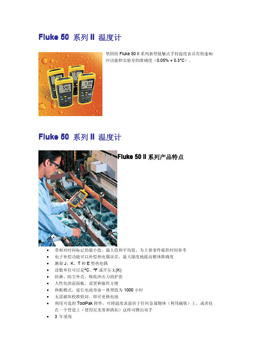
Fluke50系列II温度计
坚固的Fluke50II系列新型接触式手持温度表具有快速响
应功能和实验室的准确度(0.05%+0.3°C)。
50系列II温度计
Fluke50II系列产品特点
∙带相对时间标记的最小值、最大值和平均值,为主要事件提供时间参考
∙电子补偿功能可以补偿热电偶误差,最大限度地提高整体准确度
∙测量J、K、T和E型热电偶
∙读数单位可以是ºC、ºF或开尔文(K)
∙防淋、防尘外壳,吸收冲击力的护套
∙人性化的前面板,设置和操作方便
∙休眠模式,延长电池寿命-典型值为1000小时
∙无需破坏校准铅封,即可更换电池
∙利用可选的ToolPak附件,可将温度表悬挂于任何金属物体(利用磁铁)上,或者挂在一个管道上(使用尼龙带和搭扣)这样可腾出双手
∙3年质保
Fluke50系列II温度计
Fluke50系列II温度计
C50 TPAK
80PJ-EXT 80PK-1 80PK-3A 80PK-EXT 80PT-EXT
FlukeView Forms
FVF-SC1
80PK-IR 80PK-2A 80PK-4A 80PK-6A 80PK-7 80PT-5A。
FLUKE福禄克系列示波器中文说明书上册
2011 年 5 月(Simplified Chinese)© 2011 Fluke Corporation. 版权所有。
荷兰印刷。
规格如有更改,恕不另行通知。
所有产品名称均为其所属公司的商标。
ScopeMeter 190 Series IIFluke 190-062, -102, -104, -202, -204, -502用户手册上 册有限保修及服务范围在正常使用与维修情况下,Fluke 保证每一产品均无材料和工艺问题。
自发货之日算起,测试工具保修期为三年,附件保修期为一年。
零配件及产品修理与维护的保修期为 90 天。
此保修仅限于原始购买者或 Fluke 指定经销商的产品使用客户;而不适用于保险丝和普通电池,或任何 Fluke 认为因错误使用、改装、疏忽或因事故或非正常条件下操作或处理而导致损坏的产品。
在 90 天内,Fluke 保证软件运行符合其功能规范,并且保证软件正确记录于完好无损的介质上。
Fluke 不保证软件毫无差错或无操作中断情况。
Fluke 指定经销商只能向产品使用客户对新的或未使用过的产品提供保修,而无权以 Fluke 的名义扩充或更改保修内容。
从 Fluke 指定的销售渠道或按相应国际价格购买的产品可以得到保修。
当产品在一个国家购买而要在另一个国家修理时,Fluke 保留向客户收取修理/更换零配件费用的权利。
对于在保修期内送回 Fluke 指定的维修中心,要求按原价退款或者免费维修或更换的有故障产品,Fluke 的保修义务是有限的。
要获得保修服务,请就近联系 Fluke 指定的维修中心,或在附上故障说明、邮费和预付保险(目的地交货价)后,将产品寄往最近的 Fluke 指定的维修中心。
Fluke 对运输中可能出现的损坏情况不承担责任。
产品在维修后,将寄回给客户,邮费预付(目的地交货价)。
如果 Fluke 确定产品故障是由于错误使用、改装、事故或非正常情况下使用或操作造成的,Fluke 将提供维修费用预算并在得到认可后方进行维修。
福禄克仪表说明书

fluke中文使用手册12E

i
12E 用户手册
测试保险丝 ................................................................................................................ 9 更换电池和保险丝 ..................................................................................................... 10 保养和零件..................................................................................................................... 10 一般规格 ........................................................................................................................ 11 精确度规格..................................................................................................................... 12
用户手册
有限担保和有限责任
Fluke 公司保证本产品从购买之日起三年内,其材料和工艺均无任何缺陷。本项担保不包括保险丝、可弃置的电池或者因意 外、疏忽、误用或非正常情况下的使用或处理而损坏的产品。Fluke 也未曾授权予经销商将本保证期延长。保证期间如果需要 维修,请将测试仪表附上故障说明送到购买仪表的分销商处。
福禄克 Fluke 2AC 非接触式试电笔 说明页 说明书
PN 4245967 (Simplified Chinese)August 2010 Rev. 1, 7/11© 2010-2011 Fluke Corporation. Specifications are subject to change without notice. All rights reserved. Printed in China 2ACVoltAlert说明书首先阅读:安全须知WX警告为避免可能发生的触电或人身伤害:•如果未依照制造商的指示使用本测试仪,则本测试仪提供的保护功能可能会受到影响。
•使用前后,在本产品的额定交流电压量程内,在已知带电的电源上进行测试,以确保产品处于良好的工作状态。
•在使用本测试仪时,即使尖端没有发光,仍然可能会有电压存在。
本测试仪指示了在有电源(市电电源)电压产生足够强度静电场时的有效电压。
如果场强很低,则本测试仪可能不提供现场电压的指示。
如果有电压存在而本测试仪无法检测到,则会发生无指示的情况。
导致此类状况产生的因素包括但不限于:•屏蔽的电线/电缆•绝缘层的厚度和类型•到电压源的距离•完全绝缘、无法有效接地的使用者•凹处插座中的插孔/插座设计的差异•本测试仪和电池的状况•如果测试仪已经损坏,或者测试仪无法正常工作,请勿使用。
使用前请特别检查探头尖端是否有破裂或断头现象。
若有疑问,请将测试仪送修。
•请勿施加超过测试仪上标记的额定电压。
•测量交流 30 伏以上的电压时须特别小心,避免发生触电。
•遵守当地和国家的安全规范。
•依照当地或国家主管当局的规定使用适当的保护设备。
表 1. 符号T双重绝缘X危险电压:有触电危险W有危险。
重要信息。
请见说明书。
)符合加拿大和美国的相关标准。
P符合相关欧盟指令符合澳大利亚的相关标准~请勿将本产品作为未分类的城市废弃物处理。
请访问 Fluke 网站了解回收信息。
CAT IV 设备的设计可以使其免受初级供应电压水平所产生的瞬变的影响。
福禄克 BT521 系列蓄电池内阻分析仪 用户手册补遗 说明书
© 2016-2019 Fluke Corporation. All rights reserved.x�Manual Title: BT521 Users Supplement Issue: 3 Print Date: May 2014 Issue Date: 9/19 Revision/Date: 1, 7/15 Page Count: 3This supplement contains information necessary to ensure the accuracy of the above manual.BT521 Users Manual Supplement9/19 1Change #1, 312, 314On page 1-5, under Warning , add:• Do not short the battery terminals together. On page 1-7, in the Symbols table, add:´This product contains a Lithium-ion battery. Do not mix with solid waste stream. Spent batteries should be disposed of by a qualified recycler or hazardous materials handler per local regulations. Contact your authorized Fluke Service Center for recycling information.Change #2, 688, 721Replace page 7-7, Parts and Accessories , with:Parts and AccessoriesTable 7-1 lists the user-replaceable parts and accessories. To order replacement parts or additionalaccessories, contact your nearest Fluke Service Center. Check with your local vendor for list of parts that can be ordered in your country. See the “Contact Fluke” section.Table 0-1. Parts and AccessoriesItem No. DescriptionFluke Part Number QuantityBTL10, Basic Test Lead4542264 1 TL175, TwistGuard™ Test Leads 3521976 1 BTL_A, Voltage/Current Probe Adapter 4542258 1 BTL21, Interactive Test Probe set, with extender and temperature sensor 4542286 1 i410, AC/DC Current Clamp617727 1 BP500, 7.4 V 3000 mAh Lithium-ion battery 4398817 1 BC500, 18 V dc charger with power cord and international connector set4542299 1 Standard mini-b USB cable (cable length: 1 m) 4499448 1 BCR, Zero calibration board 4497419 1 Shoulder strap 4462888 1 Belt strap 4490316 1 Magnetic plate4329190 1 C500L Soft carrying case, large 4497130 1 Spare fuse 943121 2 Paper battery tags 4499453 100 Safety Sheet 4453942 1 Warranty card2396000 1Quick Reference Guide44539561Manual SupplementBT521 Users29/19FlukeView ®Battery (CD) containing USB driver and manuals in all languages4529552 1 BT-500 Probe-Tip, Replacement Probe tips with Red covers4397118 2 BT-500 Probe-Tip, Replacement Probe tips with Black covers4397107 2BT-500 Probe-Tip, Replacement Probe tips connector44086152Change #3, 721On page 1-3, replace Table 1-1. Standard Equipment , with:Item No. Description QuantityMainframe1 BTL10, Basic Test Lead1 TL175, TwistGuard™ Test Leads 1 BTL_A, Voltage/Current Probe Adapter1 BTL21, Interactive Test Probe set, with extender and temperature sensor 1 i410, AC/DC Current Clamp1 BP500, 7.4 V 3000 mAh Lithium-ion battery1 BC500, 18 V dc charger with power cord and International connector set1 Standard mini-b USB cable (cable length: 1 m) 1 BCR, Zero calibration board 1 Shoulder strap 1 Belt strap 1 Magnetic plate1 C500L Soft carrying case, large 1 Spare fuse2 Paper battery tags100 Probe-Tip, Replacemnet Probe tips with covers. 1 -- Safety Sheet, not shown 1 -- Warranty card, not shown1 -- Quick Reference Guide, not shown1 --FlukeView ®Battery (CD) containing USB driver and manuals in all languages, not shown1On page 1-7, Table 1-2, remove®.BT521 Users Manual Supplement On page 1-4, replace Figure 1-1. Standard Equipment, with:9/19 3。
Fluke 50 Series II 和 Fluke 51 Series II 和 Fluke 52
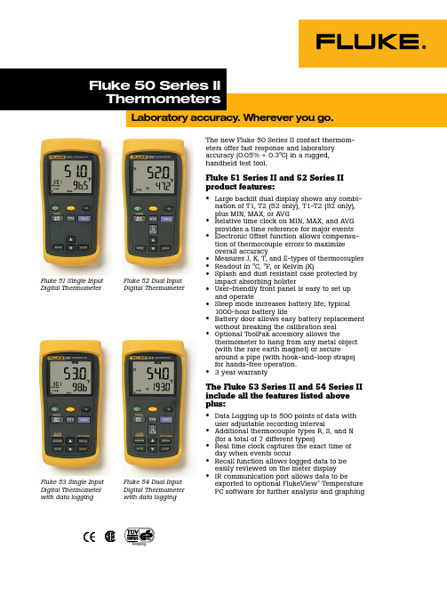
The new Fluke 50 Series II contact thermom-eters offer fast response and laboratory accuracy (0.05% + 0.3°C) in a rugged,handheld test tool.Fluke 51 Series II and 52 Series II product features:•Large backlit dual display shows any combi-nation of T1, T2 (52 only), T1-T2 (52 only),plus MIN, MAX, or AVG •Relative time clock on MIN, MAX, and AVG provides a time reference for major events •Electronic Offset function allows compensa-tion of thermocouple errors to maximize overall accuracy •Measures J, K, T, and E-types of thermocouples •Readout in °C, °F, or Kelvin (K)•Splash and dust resistant case protected by impact absorbing holster •User-friendly front panel is easy to set up and operate •Sleep mode increases battery life; typical 1000-hour battery life •Battery door allows easy battery replacement without breaking the calibration seal •Optional ToolPak accessory allows the thermometer to hang from any metal object (with the rare earth magnet) or secure around a pipe (with hook-and-loop straps)for hands-free operation.• 3 year warranty The Fluke 53 Series II and 54 Series II include all the features listed above plus:•Data Logging up to 500 points of data with user adjustable recording interval •Additional thermocouple types R, S, and N (for a total of 7 different types)•Real time clock captures the exact time of day when events occur •Recall function allows logged data to be easily reviewed on the meter display •IR communication port allows data to be exported to optional FlukeView ® TemperaturePC software for further analysis and graphingFluke 51 Single Input Digital Thermometer Fluke 52 Dual InputDigital ThermometerFluke 53 Single Input Digital Thermometer with data logging Fluke 54 Dual InputDigital Thermometerwith data logging©1999 Fluke Corporation. All rights reserved.Printed in U.S.A. 8/99 1278880 D-ENG-N Rev APrinted on recycled paper.Fluke.Keeping your world up and running.Temperature Measurement accuracy:Above -100 °C (-148 °F)J, K, T, E, and N-type**±[0.05% + 0.3°C (0.5°F) ]R** and S-type**±[0.05% + 0.4°C (0.7°F) ]Below -100 °C (-148 °F):J, K, E, and N-types ±[0.20% + 0.3°C (0.5°F) ]T-type ±[0.50% + 0.3°C (0.5°F) ]Display resolution:0.1°C / °F / K < 1000°1°C / °F / K ≥ 1000°Measurement range:J-type:-210°C to 1200°C (-346°F to 2192°F)K-type:-200°C to 1372°C (-328°F to 2501°F)T-type:-250°C to 400°C (-418°F to 752°F)E-type:-150°C to 1000°C (-238°F to 1832°F)N-type**:-200°C to 1300°C (-328°F to 2372°F)R** and S-type**:0°C to 1767°C (32°F to 3212°F)Temperature scale: ITS-90Applicable standards: NIST-175** Only the Fluke Models 53 and 54 Series II thermometers are capable of measuring N, R, and S-type thermocouples.EnvironmentalOperating temperature:-10°C to 50°C (14°F to 122°F)Storage temperature:-40°C to 60°C (-40°F to 140°F)Humidity:0% to 90%; 0°C to 35°C (32°F to 95°F)0% to 70%; 0°C to 50°C (32°F to 122°F)GeneralUnit weight:400g (14 oz)Dimensions:17.3 cm L x 8.6 cm W x 3.8 cm D(6.8 in L x 3.4 in W x 1.5 in D)Battery: 3 AA batteries; typical 1000-hour lifeCertification:CE, CSA, TÜV (pending)Safety:CSA C22.2 No. 1010.1 1992; EN 61010 Amendments 1,2Included Accessories •Impact absorbing holster •Two bead probe thermocouples (54+52)•One beaded probe thermocouple (51+53)Selection tableSpecificationsOptional ToolPak accessory allows the ther-mometer to hang from any metal object (with the rare earth magnet) or secure around a pipe (with hook-and-loop straps) for hands-free operation.。
福禄克561红外测温仪
有限担保和有限责任
Fluke 公司担保本产品自购买之日起二年内,在材料和工艺上均无 任何缺陷。本担保不适用于保险丝,一次性电池,或由于意外、 疏忽、
误用、改装、污染及非正常操作或处理引起的损坏。经销商无权以 Fluke 的名义给予其它 任何担保。如在保修期内需要保修服务,请与您就近的
Fluke 授权服务中心联系,获得产品退还授权信息; 然后将产品寄至该 服务中心,并附上产品问题描述。 本项担保是您能获得的唯一补偿。除此以外,Fluke 不提供任何明示或隐含 的担保,例如适用于某一特殊目的的隐含担保。同时,FLUKE 不对基于任 何原因或推测而导致的任何特殊、间接、附带或继起的损坏或损失负责由 于某些州或国家不允许对默示担保及附带或继起的损坏加以限制,故上述 的责任限制与规定或许对您不适用。
或者,请访问 Fluke 的全球网址:。 如要注册您的产品,请访问 。
1
561 用户手册
安全须知
XW警告
警告说明对用户可能造成危害的状况的动作。为避免触电或人身伤害,请遵循以下指南: • *请勿将激光直接对准眼睛或间接反射的表面上。 • 在使用测温仪之前,请检查机箱。如果测温仪已经损坏,请勿使用。查看是否有损
度。 • 如果未按照本手册规定的方式使用本设备,设备提供的保护可能会遭到破坏。 • 若未依照制造商的指示使用本测温仪,本测温仪提供的担保可能无效。
W小心
为避免损坏测温仪或被测设备,请保护它们免于下列伤害: • 来自包括电焊机、电感应加热器等的 EMF(电磁场)。 • 静电。 • 热冲击(由较大或突然的环境温度变化所造成 – 使用前等待 30 分钟使测温仪稳
Fluke Corporation P.O. Box 9090 Everett, WA 98206-9090 U.S.A.
Fluke L-51Omegaette 温度计说明书
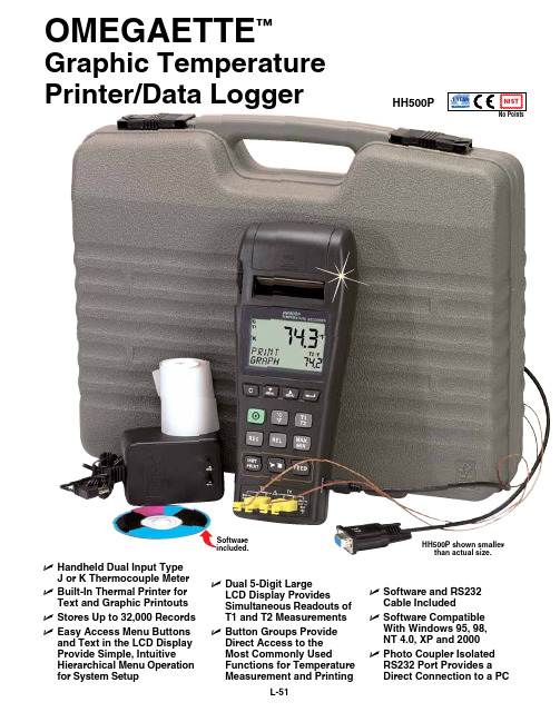
Omegaette™graphic temperaturePrinter/Data LoggerHH500P shown smallerthan actual size.U Handheld Dual Input typeJ or K thermocouple meter U Built-In thermal Printer fortext and graphic Printouts U Stores Up to 32,000 Records U easy access menu Buttons and text in the LCD DisplayProvide Simple, IntuitiveHierarchical menu Operation for System Setup U Dual 5-Digit LargeLCD Display ProvidesSimultaneous Readouts oft1 and t2 measurementsU Button groups ProvideDirect access to themost Commonly UsedFunctions for temperaturemeasurement and PrintingU Software and RS232Cable IncludedU Software CompatibleWith Windows 95, 98,Nt 4.0, XP and 2000U Photo Coupler IsolatedRS232 Port Provides aDirect Connection to a PCHH500PSoftwareincluded.L-51L-52Lpower supply, NIST certificate (no data points), 2 rolls of thermal paper, RS232 cable, Windows-based software, and 2 Type K thermocouples.Ordering Example: HH500P,Type J/K data logger.The HH500P is a powerful (32,000 records), low-cost, Type J or K temperature data logger with RS232 interfacing and graphic printing capability. The Windows-based software package (RS232 cable and software) is included and is easy to set up by following the text menu prompting on the HH500P LCD display. The HH500P is also a dual-input thermometer that allows the user to display either T1 and T2 or ∆T (T1 minus T2) readings with 0.1° resolution.The included software allows for downloading stored data or recording real-time data onto your computer.HH500P shown smallerthan actual size.The HH500P includes 2 free1 m (40") Type K insulated beaded wire thermocouples with subminiature connector and wire spool caddy Order2 Spares! Thermocouples。
Fluke 53IIB_用户手册中文版(温度计)
Simplified Chinese January 2011
© 2011 Fluke Corporation, All rights reserved. Specifications subject to change without notice. All product names are trademarks of their respective companies.
进入或退出设定(Setup) ......................................................................................... 9 改变记录间隔(Changing the Logging Interval) ...................................................... 10 改变热电偶类型 ......................................................................................................... 11 热电偶偏差的补偿...................................................................................................... 11 启动或关闭睡眠模式 .................................................................................................. 12 设定时间 .................................................................................................................... 12 改变电源频率 ............................................................................................................. 13 测量温度......................................................................................................................... 13 连接热电偶................................................................................................................. 13
福禄克测线仪2

January 2007 (Simplified Chinese)©2007 Fluke Corporation. All rights reserved.All product names are trademarks of their respective companies.MicroScanner 2Cable VerifierTM用户手册有限担保和责任限制Fluke Networks 担保在正常使用和保养的情况下,其产品没有材料和工艺上的缺陷。
主机的担保期为购买产品之日起一年。
如无另外规定,部件、零配件、产品修理和服务的担保期为 90 天。
Ni-Cad(镍镉),Ni-MH(镍氢)和 Li-Ion(锂离子)电池、电缆或其它外围设备均被视作部件或零配件。
本担保仅适用于 Fluke Networks 授权零售商的原始买方或最终用户,本担保不适用于任何 Fluke Networks 公司认为由于误用、滥用、改造、疏忽、污染或因事故或非正常的操作和使用而导致损坏的产品。
Fluke Networks担保软件能够在完全符合性能指标的条件下至少操作 90 天,并且软件是正确地记录在无缺陷的媒体上。
Fluke Networks并不担保软件毫无错误或在运行过程中不出现中断的情况。
Fluke Networks 授权的零售商应仅对最终用户就新的和未用的产品提供本担保,但无权代表 Fluke Networks 公司提供额外或不同的担保。
仅对在 Fluke Networks 授权的销售点的购买者或支付适当的国际价购买产品时提供担保支持。
在一国购买的产品需在他国修理时,Fluke Networks 有权向买方要求负担重大修理/零件更换费用。
Fluke Networks 的担保为有限责任,由 Fluke Networks 决定是否退还购买金额、免费修理或更换在担保期间退回 Fluke Networks 授权的维修中心的瑕疵产品。
Fluke 数字漏电流计应用说明书

Application NoteF r o m t h e F l u k e D i g i t a l L i b r a r y @ w w w.f l u k e.c o m /l i b r a r yPower interruptions Unfortunately the unconditional availability of electrical power can never be taken for granted. In fact, quite frequently interrup-tions occur of various durations. Many of these pass unnoticed, but some may prevent your equipment from working prop-erly. The longest interrupts are obviously the ones that make all lights go down and all equip-ment stop. But sometimes, we see only a single piece of equip-ment blink as if the power has been interrupted, after which operation continues immediately with nothing else apparently indicating that anything has happened. This then raises ques-tion of whether the ‘hiccough’ was due to a power malfunction, or to the fact that the affected piece of equipment itself is faulty.An oscilloscope from the ScopeMeter 190 Series II can be a valuable tool in finding answers here, as it allows you to detect these short-duration interrupts of the electrical power system.Pulse width triggering ScopeMeter 190 Series II oscil-loscopes are equipped with a pulsewidth-trigger mode. This trigger mode is able to detect, for instance, the pulse width in Electrical energy is the driving force of today’s world. It is available almost everywhere you go, and is capable of driving all sorts of equipment from heating and cook-ing equipment, through motors and ventilators to the PC that this application note is written on. And it’s available all the time. Or is it?a repetitive signal. But it is also capable of detecting the absence of a signal for a certain amount of time, for instance of the mains voltage.When the oscilloscope is used to monitor the mains signal, an interruption will trigger the oscilloscope and the waveform information will be “frozen” in the oscilloscope’s memory. If more such events should occur, the scope screen will automati-cally be updated for each such event, and the successive events will be stored in the REPLAY-memory. The whole sequence of events can then be re-played and analyzed from the scope screen which also displays a date- and timestamp. The replay screens can be copied to a PC for documenting and archiving.Here’s a set-up that allows you to detect the moments that the mains voltage is interrupted.Instrument set-up The mains voltage is a sinusoidal ac voltage. This means that it is half the time positive and half the time negative. A full cycle takes 20 ms if the line frequency is 50 Hz, or 16.6 ms for 60 Hz systems.Given this ac voltage, we can set-up the ScopeMeter to detect if the mains voltage is inter-rupted. To do so, we set up the ScopeMeter to recognize the Measuring short interrupts on the mains with a Fluke ScopeMeter ®190 Series II absence of any voltage for longer than ¾ of a cycle, this is 15 ms (or 12.5 ms for a 60 Hz system), as this can only happen during an interrupt of the normal cycle.Connect the ScopeMeter probe to input A, and connect the probe ground clip (alligator) to the mains neutral. Connect the probe tip to the ‘live’ mains line. Be careful in making these connections as the mains system carries hazardous voltage! Use only the safety-designed acces-sories described with the Fluke ScopeMeter.Alternatively, if a low-voltage transformer is part of the system under test, measure on the low-voltage side of that transformer as this provides the necessary safety barrier.Select the ScopeMeter to work in ‘Scope’ mode, and make sure the instrument is in ‘Auto’ mode (see upper right corner of the screen). If it is not in ‘Auto’ mode,2 Fluke Corporation Measuring short interrupts on the mains with a ScopeMeter ® 190 Series II press the green AUTO/MANUAL button to set the indicator in the upper-right corner to read ‘Auto’. A continuous sinewave will now be visible. Change the time-base setting to give about 2 or3 cycles per horizontal division, so select 20 or 40 ms/div (see figure 1).Change the horizontal trigger position to a position to the right of the screen, e.g. at a position three divisions from the right side of the screen. Look at the ∫-symbol in Figure 1. A continu-ous sinewave will remain visible and is repeatedly refreshed on screen. The vertical position of the ∫-symbol marks the voltage level that the trigger system is responding to.Now select the ‘Trigger’ menu, and press F4 (Trigger options) and select “Pulse Width on A” from the menu. Press Enter. You will notice that a new menu layer appears. Select the negative oriented pulses (‘U’-shaped pulses) and the condition ‘Pulsewidth >t ’, select ‘Update on trigger’ in order to catch suc-cessive interrupts rather than only one.Press Enter until all selections are made, and the menu text is switched off again. The up and down controls (s and t) can now be used to change the time dura-tion of the interrupts that the scope will respond to. Set this to 15 ms (or 12.5 ms when working on a 60 Hz system). The oscil-loscope is now ready to respond to any short-term interrupt of the mains voltage.Figures 3 and 4 provide some examples of power interrupts that were captured.Conclusion Malfunctioning of electronic equipment is sometimes related to short-duration interrupts of the mains supply. This calls for a tool to find such interrupts, complete with date and time of occur-rence. Fluke ScopeMeter 190 Series II oscilloscopes are capa-ble of conveniently detecting and storing such power inter-rupts. Even if many such events occur over a longer period of time, up to 100 individual events can be stored, complete with date- and time-indicator, making longer-term power monitoring easier than ever.Fluke Corporation PO Box 9090, Everett, WA 98206 U.S.A.Fluke Europe B.V. PO Box 1186, 5602 BD Eindhoven, The NetherlandsFor more information call: In the U.S.A. (800) 443-5853 or Fax (425) 446-5116 In Europe/M-East/Africa +31 (0) 40 2675 200 or Fax +31 (0) 40 2675 222 In Canada (800)-36-FLUKE or Fax (905) 890-6866 From other countries +1 (425) 446-5500 or Fax +1 (425) 446-5116 Web access: ©2005-2011 Fluke Corporation. Specifications subject to change without notice. Printed in U.S.A. 4/2011 2543312B A-EN-N Pub_ID: 10616-eng, rev 01Modification of this document is not permitted without written permission from Fluke Corporation.Fluke. Keeping your worldup and running.Figure 1: 60 Hz mains voltage using AUTO-mode.Figure 2: Menu layer for pulse-width triggersettings.Figure 3: Power disruption due to a loosecontact in the wiring.Figure 4: Interrupt as stored in the replay-memory. Note the date- and time-markers that were automatically attached to the recording.。
2638a_ user manual_fluke_chinese 用户手册说明书

June 2013 (Simplified Chinese) Rev. 1, 5/16© 2013 -2016 Fluke Corporation. All rights reserved. Specifications are subject to change without notice. All product names are trademarks of their respective companies. 2638AHYDRA Series III Data Acquisition Unit用户手册有限担保及责任范围Fluke 公司保证其每一个Fluke的产品在正常使用及维护情形下,其用料和做工都是毫无瑕疵的。
保证期限是一年并从产品寄运日起开始计算。
零件、产品修理及服务的保证期是 90 天。
本保证只提供给从Fluke 授权经销商处购买的原购买者或最终用户, 且不包括保险丝、电池以及因误用、改变、疏忽、或非正常情况下的使用或搬运而损坏(根据 Fluke 的意见而定)的产品。
Fluke 保证在 90 天之内,软件会根据其功能指标运行,同时软件已经正确地被记录在没有损坏的媒介上。
Fluke 不能保证其软件没有错误或者在运行时不会中断。
Fluke 仅授权经销商将本保证提供给购买新的、未曾使用过的产品的最终用户。
经销商无权以 Fluke 的名义来给予其它任何担保。
保修服务仅限于从 Fluke 授权销售处所购买的产品,或购买者已付出适当的Fluke国际价格。
在某一国家购买而需要在另一国家维修的产品,Fluke 保留向购买者征收维修/更换零件进口费用的权利。
Fluke 的保证是有限的,在保用期间退回 Fluke 授权服务中心的损坏产品,Fluke有权决定采用退款、免费维修或把产品更换的方式处理。
欲取得保证服务,请和您附近的Fluke服务中心联系,或把产品寄到最靠近您的Fluke服务中心(请说明故障所在,预付邮资和保险费用,并以 FOB 目的地方式寄送)。
Fluke 50 Series Multifunction Thermometer 说明书
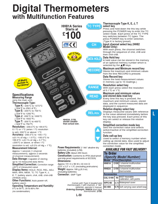
L-50SpecificationsMeasuring Range (only the main unit)Thermocouple Type:Type K:-200°C to 1372°C (-328°F to 2501.6°F); Type E:-200°C to 700°C (-328°F to 1292°F);Type J:-200°C to 1000°C (-328°F to 1832°F);Type T:-200°C to 400°C (-328°F to 752°F)Resolution: -200.0°C to 199.9°C; 0.1°C or 1°C (when 1°C resolution is set); 200°C or above: 1°CAccuracy: -200.0°C to -100.1°C:±(0.1% of rdg + 1.0°C); -100.0°C to 199.9°C: ±(0.1% of rdg + 0.7°C);+200°C or above, or when 1°Cresolution is set: ±(0.2% of rdg + 1°C)Measurement Interval: Approx 1 second (1-channelmeasurement); approx 2 seconds (2-channel measurement)Data Storage: Capable of storing up to 10 measured data itemsSimplified Correction: Correction range:±20°C of measured valueDisplay Items: HOLD, RCD, REL, ADJ,MAX, MIN, MEM, °C; TC Type K, J, E, T, battery alarm, chA, chB, chA-chB (HH82A only)Other Functions: Auto power-off,battery alarmOperating Temperature and Humidity:0°C to 50°C, 20 to 80% RH (no condensation)Power Requirements:2 “AA” alkaline dry batteries (included) (LR6)Battery Life:About 450 hoursConstruction:Conforms to IP54 (dust-proof and drip-proof requirements of IEC529)Dimensions:Approx 151 H x 56 W x 33 mm D(5.9" x 2.2" x 1.3") (excluding protrusions)Weight:Approx 180 g (6.3 oz) (including batteries)Connector:SMP TypeComes with Type K beaded wire thermocouple (1 per channel), 2 “AA”batteries, operator’s manual.Ordering Example: HH82A dual inputthermometer, £150.HH82A, £150,shown smaller than actual size.HH81A Series Starts at£100Digital Thermometerswith Multifunction FeaturesThermocouple Type K, E, J, T select keyPress and hold down the this key while pressing the POWER key to enter the TC select mode. Each press of the TC TYPE key switches between TC types. The press POWER key to enter selection.(Type K is factory preset)Input channel select key (HH82 Model Only)With each press, the channel switches through the sequence of chA, chB and then chA-chB.Data Hold keyA held value can be stored in the memory of an optional memory number which is selected by the keys.Maximum and Minimum record key Stores the maximum and minimum values from the time RECORD is pressed.Data Record keyStores the held measurement values in memory (up to 10 readings.)Resolution select keyWith each press select the resolution of 0.1°C or 1°C.Maximum and minimum values and stored data read keyEvery time this key is pressed, the maximum and minimum values, stored data, and the current measured data are displayed in sequence.Relative display select keyDisplays measured values with reference to the value obtained immediately before the key was pressed. Each press of this key can select or release the relative display.Simplified correction mode key Sets the correction value and selects active/inactive of the simplified correction function.Data call-up keyUsed to select a memory number when calling up stored data. Also used to adjust the correction value for the simplified correction mode.A l l M o d e l sA v a i l a b l e f o rF a s t D e l i v er y!G ET I T F I X E D ,G E TA F R E E L O AN ER !CANADA www.omega.ca Laval(Quebec)1-800-TC-OMEGA UNITED KINGDOM Manchester,England0800-488-488GERMANY www.omega.deDeckenpfronn,Germany************FRANCE www.omega.fr 088-466-342BENELUX www.omega.nl 0800-099-33-44UNITED STATES 1-800-TC-OMEGA Stamford,CT.CZECH REPUBLIC www.omegaeng.cz Karviná,Czech Republic596-311-899TemperatureCalibrators, Connectors, General Test and Measurement Instruments, Handheld Instruments for Temperature Measurement, Ice Point References, Indicating Labels,Crayons, Cements and Lacquers, Infrared Temperature Measurement Instruments, Recorders, Relative Humidity Measurement Instruments, PT100 Probes, PT100 Elements,Temperature & Process Meters, Timers and Counters,Temperature and Process Controllers and Power Switching Devices, Thermistor Elements, Probes and Assemblies,Thermocouples, Thermowells and Head and WellAssemblies, Transmitters, Thermocouple Wire, RTD ProbesPressure,Strain and ForceDisplacement Transducers, Dynamic Measurement Force Sensors, Instrumentation for Pressure and StrainMeasurements, Load Cells, Pressure Gauges, PressureReference Section, Pressure Switches, Pressure Transducers,Proximity Transducers, Regulators, Pressure Transmitters,Strain Gauges, Torque Transducers, ValvespH and ConductivityConductivity Instrumentation,Dissolved OxygenInstrumentation,Environmental Instrumentation,pH Electrodes and Instruments,Water and Soil Analysis InstrumentationHeatersBand Heaters,Cartridge Heaters,Circulation Heaters,Comfort Heaters,Controllers,Meters and SwitchingDevices,Flexible Heaters,General Test and Measurement Instruments,Heater Hook-up Wire,Heating Cable Systems,Immersion Heaters,Process Air and Duct,Heaters,Radiant Heaters,Strip Heaters,Tubular HeatersFlow and LevelAir Velocity Indicators,Doppler Flowmeters,LevelMeasurement,Magnetic Flowmeters,Mass Flowmeters,Pitot Tubes,Pumps,Rotameters,Turbine and Paddle Wheel Flowmeters,Ultrasonic Flowmeters,Valves,Variable Area Flowmeters,Vortex Shedding FlowmetersData AcquisitionAuto-Dialers and Alarm Monitoring Systems,Communication Products and Converters,Data Acquisition and Analysis Software,Data LoggersPlug-in Cards,Signal Conditioners,USB,RS232,RS485and Parallel Port Data Acquisition Systems,Wireless Transmitters and Receivers。
fluke万用表使用方法

fluke万用表使用方法英文回答:Fluke multimeters are widely used in electrical and electronic testing and troubleshooting. As a professional electrician, I have been using Fluke multimeters for many years and I can share with you the proper usage of these versatile tools.Firstly, it is important to understand the basic functions and features of a Fluke multimeter. These devices are capable of measuring various electrical parameters such as voltage, current, resistance, capacitance, and frequency. They are equipped with a digital display that provides accurate readings and may also offer additional featureslike continuity testing and diode testing.To use a Fluke multimeter, you need to follow these steps:1. Set the multimeter to the appropriate function. Depending on what parameter you want to measure, you need to select the corresponding function on the dial or button of the multimeter. For example, if you want to measure voltage, set the dial to the "V" or "ACV" position.2. Connect the test leads. The multimeter comes with two test leads, a red one and a black one. The red lead is usually connected to the positive terminal or the "VΩmA" port, while the black lead is connected to the negative terminal or the "COM" port. Make sure the leads are securely connected.3. Make the measurement. Once the multimeter is set and the test leads are connected, you can make the measurement. For example, if you want to measure the voltage across a circuit, touch the red lead to the positive terminal and the black lead to the negative terminal. The multimeterwill display the voltage reading on the digital display.4. Interpret the reading. After making the measurement, it is important to interpret the reading correctly. Payattention to the unit of measurement and any prefixes that may be displayed, such as millivolts (mV) or kilohms (kΩ). Also, consider the range of the measurement and make sureit falls within the expected values.It is worth mentioning that Fluke multimeters are known for their durability and accuracy. They are designed to withstand harsh working conditions and provide reliable measurements. Moreover, Fluke offers a wide range of multimeters to suit different needs and budgets, from basic models for hobbyists to advanced models for professionals.中文回答:Fluke万用表广泛用于电气和电子测试和故障排除。
FLUKE 51-II型温度仪
档案编号:设备仪器档案
设备名称:FLUKE 51-II型温度仪
设备编号:FLUK.01
使用部门:生产部
填写日期:
目录
(一)存档资料记录卡 (3)
(二)仪器设备相关手册存放记录 (4)
(三)设备主要技术特性 (5)
(四)附属设备及计量仪表 (6)
(五)设备易损件清单 (7)
(六)设备开箱检查验收单 (8)
(七)设备安装情况记录 (9)
(八)设备调试验收单 (10)
(九)设备保养维修记录 (11)
(十)设备事故报告 (12)
(十一)鉴定证书及确认说明 (13)
(十二)出厂报告 (16)
(一)存档资料记录卡
(二)仪器设备相关手册存放记录
(三)设备主要技术特性
(四)附属设备及计量仪表
(五)设备易损件清单
(六)设备开箱检查验收单
(七)设备安装情况记录
(八)设备调试验收单
(九)设备保养维修记录
(十)设备事故报告
(十一)鉴定证书及确认说明
(十二)出厂报告。
Fluke 51Series II_用户手册中文版(温度计)

通信地址:
Fluke Corporation
Fluke Europe B.V.
P.O. Box 9090
P.O. Box 1186
Everett, WA 98206-9090 5602 BD Eindhoven
USA(美国)
The Netherlands(荷兰)
或浏览我们的万维网站点:
指标................................................................................................................................ 13 环境........................................................................................................................... 13 综合性能.................................................................................................................... 14 80 PK-1 热电偶 (随温度计提供) ................................................................................ 14 电气特性.................................................................................................................... 14
FLUKE 51 52 Series II 说明书

®51 & 52 Series IIThermometerUsers ManualEnglishSeptember 1999© 1999 Fluke Corporation, All rights reserved. Printed in USAAll product names are trademarks of their respective companies.Limited Warranty & Limitation of LiabilityThis Fluke product will be free from defects in material and workmanship for 3 years from the date of purchase. This war-ranty does not cover fuses, disposable batteries or damage from accident, neglect, misuse or abnormal conditions of opera-tion or handling. Resellers are not authorized to extend any other warranty on Fluke’s behalf. To obtain service during the warranty period, send your defective tester to the nearest Fluke Authorized Service Center with a description of the problem. THIS WARRANTY IS YOUR ONLY REMEDY. NO OTHER WARRANTIES, SUCH AS FITNESS FOR A PARTICULAR PURPOSE, ARE EXPRESSED OR IMPLIED. FLUKE IS NOT LIABLE FOR ANY SPECIAL, INDIRECT, INCIDENTAL OR CONSEQUENTIAL DAMAGES OR LOSSES, ARISING FROM ANY CAUSE OR THEORY. Since some states or countries do not allow the exclusion or limitation of an implied warranty or of incidental or consequential damages, this limitation of liability may not apply to you.Fluke Corporation P.O. Box 9090 Everett WA 98206-9090Fluke Europe B.V. P.O. Box 11865602 B.D. Eindhoven The Netherlands10/96Table of ContentsTitle Page Introduction (1)Contacting Fluke (1)Getting Started (4)Components (5)Display Elements (6)Buttons (7)Using the Thermometer (9)Changing Setup Options (9)Entering or Exiting Setup (9)Setup Options (9)Changing a Setup Option (10)Measuring Temperatures (11)Connecting a Thermocouple (11)Displaying Temperatures (11)Holding the Displayed Readings (12)Viewing the MIN, MAX, and AVG Readings (12)Using the Offset to Adjust for Probe Errors (12)i51 & 52 Series IIUsers ManualMaintenance (13)Replacing the Batteries (13)Cleaning the Case and Holster (13)Calibration (13)Specifications (13)Environmental (13)General (14)80 PK-1 Thermocouple (supplied with thermometer) (14)Electrical (14)Replacement Parts and Accessories (15)ii51 & 52 Series IIIntroductionThe Fluke Model 51 and Model 52 Thermometers (“the thermometer”) are microprocessor-based, digital thermometers designed to use external J-, K-, T-, and E-type thermocouples (temperature probes) as temperature sensors.Use the thermometer only as specified in this manual. Otherwise, the protection provided by the meter may be impaired.Refer to safety information in Table 1 and meter symbols in Table 2.Contacting FlukeTo order accessories, receive assistance, or locate the nearest Fluke distributor or Service Center, call: 1-888-993-5853 in USA & Canada+31-402-678-200 in Europe+81-3-3434-0181 in Japan+65-738-5655 in Singapore+1-425-446-5500 from other countriesAddress correspondence to:Fluke Corporation Fluke Europe B.V.P.O. Box 9090P.O. Box 1186Everett, WA 98206-9090 5602 BD EindhovenUSA The Netherlands151 & 52 Series II Users Manual2Table 1. Safety InformationW WarningA Warning identifies conditions and actions that pose hazards to the user. To avoid electrical shock or personal injury, follow these guidelines:•Before using the thermometer inspect the case. Do not use the thermometer if it appears damaged. Look for cracks or missing plastic. Pay particular attention to the insulation around the connectors.•Disconnect the thermocouple(s) from the thermometer before opening the case.•Replace the batteries as soon as the battery indicator (B) appears. The possibility of false readings can lead to personal injury.•Do not use the thermometer if it operates abnormally. Protection may be impaired. When in doubt, have the thermometer serviced.•Do not operate the thermometer around explosive gas, vapor, or dust.•Do not apply more than the rated voltage, as marked on the thermometer, between the thermocouple(s), or between any thermocouple and earth ground.51 & 52 Series IIIntroductionTable 1. Safety Information (cont.)W Warning (cont.)•Model 52: Measurement errors may occur if voltages on the measurement surfaces result in potentials greater than 1 V between the two thermocouples. When potential differences are anticipated between the thermocouples, use electrically insulated thermocouples.•When servicing the thermometer, use only specified replacement parts.•Do not use the thermometer with any part of the case or cover removed.CautionA Caution identifies conditions and actions that may damage the meter or the equipment under test.•Use the proper thermocouples, function, and range for your thermometer.•Do not attempt to recharge the batteries.•To prevent explosion, do not throw batteries into a fire.•Follow local laws or regulations when disposing of batteries.•Match the + and − polarities of the battery with the battery case.351 & 52 Series II Users Manual4Table 2. International SymbolsW Refer to the manual for information about thisfeature.P Complies with European Union directives.M plies with relevant Canadian StandardsAssociation directives.Getting StartedEverything in this Users Manual applies both to Models 51 and 52 unless otherwise indicated.To become familiar with the thermometer, study the following:•Figure 1 and Table 3 describe the components.•Figure 2 and Table 4 describe the display.•Table 5 describes the functions of the buttons. Then read the following sections.51 & 52 Series II Getting Started5ComponentsFigure 1. ComponentsTable 3. ComponentsAThermocouple T1 inputB Model 52: Thermocouple T2 inputC HolsterD DisplayE ButtonsF Battery door GBatteries51 & 52 Series II Users Manual6Display Elementsaas02f.epsFigure 2. Display ElementsTable 4. Display ElementsAThe thermocouple measurement includes an offset. See "Changing Setup Options."BThe displayed readings do not change.C A shift function is in progress.DSetup is in progress.E Low battery. Replace the batteries.FPrimary Display.Model 51: T1 reading.Model 52: T1, T2, or T1-T2 reading.G The temperature unit.H Secondary Display: MAX, MIN, AVG, or offset.Model 52: T1or T2 reading.I The thermocouple type.JTime Display: The elapsed time.Getting StartedButtonsTable 5. ButtonsA Press A to turn the thermometer on or off.G(Shift function)Press G, M (CANCEL) to stop displaying the minimum, maximum, and average readings in the secondary display.Q Press Q to turn the backlight on and off. The backlight turns off after 2 minutes without any button presses. If the battery is low, the backlight is disabled.M Press M to step through the maximum, minimum, and average readings. When viewing logged readings, shows the maximum, minimum, and average of the logged readings.Press G, M (CANCEL) to turn off this display.C Press C to switch between Celsius (o C), Fahrenheit (o F), and Kelvin (K).h Press h to freeze or unfreeze the displayed readings.Press h when turning on the thermometer to test the display. All display elements appear.T Model 52: Press T to toggle showing the T1, T2, and T1-T2 (differential temperature measurement) in the primary or secondary display.Users ManualTable 5. Buttons (cont.)D Press D to start or exit Setup. (See "Changing Setup Options.")K Press K to scroll to the Setup option you want to change.Press K to increase the displayed setting.N Press N to scroll to the Setup option you want to change.Press N to decrease the displayed setting.E Press E to enter a Setup option.Press E again to store the displayed setting in memory.Using the ThermometerUsing the Thermometer1. Plug the thermocouple(s) into the input connector(s).2. Press A to turn on the thermometer.After 1 second the thermometer displays the first reading. If no thermocouple is plugged into the selected input or the thermocouple is "open," the display shows "- - - -" Changing Setup OptionsUse Setup to change the thermocouple type, offset, sleep mode, and line frequency settings.The thermometer stores the settings in its memory. Setup settings reset only when the batteries are removed for more than 2 minutes.Entering or Exiting SetupWhen the thermometer is in Setup mode, the display shows s.• PressD to start or exit Setup.Setup OptionsOptionMenuItem Settings ThermocoupleTypeTYPE J, K, T, or EOffset O T1 or T2 (Model 52) Sleep Mode SLP on (sleep mode on)or 0FF (sleep modeoff)Line Frequency Li ne50 H (50 Hz)or 60 H (60 Hz)Users ManualChanging a Setup Option1. Press K or N to scroll to the setup option youwant to change.2. Press E to indicate that you want to change thissetting.3. Press K or N until the setting you want to useappears on the display.4. Press E to store the new setting in memory.NotesSetup is disabled in MIN MAX mode.Offset:The primary display shows the temperature plusthe offset and the secondary display shows theoffset. Remember to reset the offset to 0.0 whenit is no longer needed. The offset automaticallyresets to 0.0 when you change the thermocoupletype. Model 52: You can store individual offsetsfor T1 and T2.Sleep mode:The thermometer enters sleep mode if no button press occurs for 20 minutes. Pressing any button wakes the thermometer and returns it to its previous state. Sleep mode becomes enabled each time you turn on the thermometer and is automatically disabled in MIN MAX mode.Line frequency:For optimum rejection of line noise, the thermometer must be set for the local line frequency.Measuring TemperaturesMeasuring TemperaturesConnecting a ThermocoupleTo change the thermocouple type, see “Changing Setup Options.” The North American ANSI Color Code is: Type J K E T N Color Black Yellow Purple Blue Orange 1.Plug a thermocouple into the input connector(s).(Make sure that the polarity is correct.)2.Set the thermometer for the correct thermocoupletype.Displaying Temperatures1.Press C to select the correct temperature scale.2.Hold or attach the thermocouple(s) to themeasurement location.The temperature reading appears in the primarydisplay.3.Model 52: Press T to toggle between showing theT1, T2, and T1-T2 readings in the primary orsecondary display.NotesThe display shows "- - - -" when a thermocouple is not connected.The display shows 0L (overload) when the temperature being measured is outside the thermocouple’s valid range.Model 52: If only thermocouple T2 is connected, the T2 reading appears in the primary display.Users ManualHolding the Displayed Readings1. Press h to freeze the readings on the display.The display shows H.2. Model 52: Press T to toggle showing the T1, T2, orT1-T2 readings in the primary or secondary display.3. Press h again to turn off the HOLD function. Viewing the MIN, MAX, and AVG Readings1. Press M to step through the maximum (MAX),minimum (MIN), or the average (AVG) readings.The elapsed time since entering MIN MAX mode, orthe time at which the minimum or maximum occurred, appears on the display.2. Press G, M (CANCEL) to exit MIN MAX ing the Offset to Adjust for Probe ErrorsUse the offset option in Setup to adjust the thermometer’s readings to compensate for the errors of a specific thermocouple.The allowable adjustment range is ± 5.0 o C or K, and± 9.0 o F.1. Plug the thermocouple into the input connector.2. Place the thermocouple in a known, stabletemperature environment (such as an ice bath or adry well calibrator).3. Allow the readings to stabilize.4. In Setup change the offset until the primary displayreading matches the calibration temperature. (See"Changing Setup Options.")MaintenanceMaintenanceReplacing the BatteriesRefer to the safety information in Table 1 before replacing the batteries.1. Turn off the thermometer if necessary.2. Loosen the screw and remove the battery door.3. Replace the three AA batteries.4. Replace the battery door and tighten the screw. Cleaning the Case and HolsterUse soap and water or a mild commercial cleaner.Wipe with a damp sponge or soft rag.CalibrationTo ensure that the thermometer performs to its accuracy specifications, Fluke recommends that you calibrate the thermometer annually, starting one year after purchase.To calibrate the thermometer, contact Fluke for the Service Center nearest you or follow the calibration procedure in the service manual listed in "Replacement Parts and Accessories."SpecificationsEnvironmentalOperatingTemperature−10 o C to 50 o C(14 o F to 122 o F)Storage Temperature−40 o C to +60 o C(−40 o F to +140 o F)Humidity0 % to 90 %: −10 o C to 35 o C(14 o F to 95 o F)0 % to 70 %: −10 o C to 50 o C(14 o F to 122 o F)Users ManualGeneralWeight280 g (10 oz)Dimensions (without holster)2.8 cm × 7.8 cm × 16.2 cm (1.1 in × 3 in × 6.4 in)Battery 3 AA batteriesCertification P, ) (TÜV pending)Safety CSA C22.2 No. 1010.1 1992EN 61010 Amendments 1, 2CAT I OVERVOLTAGE (Installation)CATEGORY I, Pollution Degree 2per IEC1010-1** Refers to the level of Impulse Withstand Voltage protection provided. Equipment of OVERVOLTAGE CATEGORY I is equipment for connection to circuits in which measures are taken to limit the transient over voltages to an appropriate low level. Example include protect electronic circuits.80 PK-1 Thermocouple (supplied with thermometer)Type Type K, Chromel Alumel, bead styleTemperatureRange−40 oC to +260 oC(−40 oF to +500 oF)Accuracy± 1.1 oC (± 2.0 oF)ElectricalMeasurementRangeJ-type: −210 oC to +1200 oC(−346 oF to + 2192 oF)K-type: −200 oC to +1372 oC(−328 oF to +2501 oF)T-type: −250 oC to +400 oC(−418 oF to +752 oF)E-type: −150 oC to +1000 oC(−238 oF to +1832 oF)DisplayResolution0.1 oC / oF / K < 1000o1.0 oC / oF / K ≥ 1000oReplacement Parts and Accessories Electrical (cont.)Measurement Accuracy, T1, T2, or T1-T2 (Model 52)J-, K-, T-, and E-type: ±[0.05 % of reading + 0.3 o C (0.5 o F)][below −100 o C (−148 o F): add 0.15 % of reading for J-, K-, E-, and N-type; and 0.45 % of reading for T-type]Temperature Coefficient 0.01 % of reading + 0.03 o C per o C (0.05 o F per o F) outside the specified +18 o C to 28 o C (+64 o F to +82 o F) range[below −100 o C (−148 o F): add0.04 % of reading for J-, K-, E-, and N-type; and 0.08 % of reading for T-type]Maximum Differential Common Mode Voltage 1 V (Maximum voltage difference between T1 and T2)TemperatureScaleITS-90ApplicableStandardsNIST-175Accuracy is specified for ambient temperatures between 18 o C (64 o F) and 28 o C (82 o F) for a period of 1 year. The above specifications do not include thermocouple error.Replacement Parts and AccessoriesAccessory Part Number Holster and Flex Stand™ Assembly1272438 AA NEDA 15A IEC LR6 batteries37675680PK-1 K-Type Bead Thermocouple773135CD-ROM1276106 Service Manual1276123Users Manual。
- 1、下载文档前请自行甄别文档内容的完整性,平台不提供额外的编辑、内容补充、找答案等附加服务。
- 2、"仅部分预览"的文档,不可在线预览部分如存在完整性等问题,可反馈申请退款(可完整预览的文档不适用该条件!)。
- 3、如文档侵犯您的权益,请联系客服反馈,我们会尽快为您处理(人工客服工作时间:9:00-18:30)。
认识仪表......................................................................................................................... 4 部件 ........................................................................................................................... 5 显示屏幕 .................................................................................................................... 6 按钮 ........................................................................................................................... 7
10/96
目录
条目
页码
简介 ................................................................................................................................ 1 如何与 Fluke 联系...................................................................................................... 1
请根据本说明书的步骤使用温度计,否则,温度计仪表的 保护设施可能会受到损坏。
请参阅表 1 的安全信息以及表 2 的国际符号。
如何与 Fluke 联系
欲订购附件、寻求协助、或找出离您最近的 Fluke 经销商 或服务中心的地址,请打电话:
1-888-99-FLUKE (1-888-993-5853) 美国 1-800-36-FLUKE (1-800-363-5853) 加拿大 +31-402-678-200 欧洲 +81-3-3434-0181 日本 +65-738-5655 新加坡 +1-425-446-5500 其它国家
为注册您的产品,请访问:
1
51 & 52 Series II 用户手册
表 1. 安全信息
W警告
警告 一词指出对使用者构成危险的状况或动作。为避免触电或人身受到伤害,请遵循以下指南: • 使用温度计以前应先检查外壳。如果温度计外表已经损坏就不要使用。检查外壳是否有断裂或缺少塑料件。特别注意
接头周围的绝缘。 • 打开仪表外壳以前,应先把热电偶与温度计的连接断开。
• 显示屏幕出现电池 (B) 标志时,应马上更换电池。错误读数可能会导致人身受到伤害。
• 如果温度计工作不正常,就不要使用它。保护设施可能已遭到损坏。若有疑问,应把温度计送去维修。 • 反光物体会导致测得的温度比实际温度要低。这些物体会产生烧伤危险。 • 切勿在爆炸性的气体、蒸汽或灰尘附近使用温度计。 • 请勿从地线连接至大于 30 V 交流(有效值)、42 V (峰值)、60 V 直流的电压。
指标................................................................................................................................ 13 环境........................................................................................................................... 13 综合性能.................................................................................................................... 14 80 PK-1 热电偶 (随温度计提供) ................................................................................ 14 电气特性.................................................................................................................... 14
i
51 & 52 Series II 用户手册
维护................................................................................................................................ 13 更换电池.................................................................................................................... 13 清理外壳及护套 ......................................................................................................... 13 校准........................................................................................................................... 13
®
51 & 52 Series II Thermometer
Simplified Chinese September 1999 Rev.2, 11/10
© 1999-2010 Fluke Corporation, All rights reserved. All product names are trademarks of their respective companies. Specifications subject to change without notice.
更换部件和附件.............................................................................................................. 15
ii
51 & 52 Series II
简介
Fluke 51 型和 52 型温度计(以下简称“温度计, thermometer”)是使用微处理机的数字式温度计,它们 能接受以下类型的热电偶(温度探头)输入:J-, K-, T-, 和 E-类型。
使用温度计 ..................................................................................................................... 9 改变设定(Setup)选项 ................................................................................................. 9
2
51 & 52 Series II 简介
通信地址:
Fluke Corporation
Fluke Europe B.V.
P.O. Box 9090
P.O. Box 1186
Everett, WA 98206-9090 5602 BD Eindhoven
USA(美国)
The Netherlands(荷兰)
或浏览我们的万维网站点:
用户手册
有限的保证及责任范围
Fluke 公司保证本产品从购买日起三年内,其用料和做工都是毫无瑕疵的。此保证不包括保险丝及电池在内,也不包括因意 外、疏忽、误用、或在非正常情况下的使用或搬运而导致的损坏。Fluke 也未曾授权予经销商将本项保证期延长。保证期间, 如果有维修上的需要,请将损坏的测试仪表(附上故障说明)送到您最近的 Fluke 授权服务中心。
Fluke Corporation
Fluke Europe B.V.
P.O. Box 9090
P.O. Box 1186
Everett, WA 98206-9090 5602 B.D. Eindhoven
USA
The Netherlands
为注册您的产品,请访问ຫໍສະໝຸດ
进入或退出设定(Setup) ......................................................................................... 9 Setup 选项 ................................................................................................................. 9 改变设定(Setup) 选项 ........................................................................................... 10 测量温度......................................................................................................................... 11 连接热电偶................................................................................................................. 11 显示温度 .................................................................................................................... 11 保持显示的温度读数 .................................................................................................. 12 查看 MIN, MAX, 和 AVG 读数.................................................................................... 12 用偏差值调整温度探头的误差......................................................................................... 12
