土木工程专业钢筋混凝土结构抗震性能外文翻译文献
土木工程专业文献翻译中英文
The frame structure anti- earthquake conceptdesignThe disaster has an earthquake dashing forward sending out nature, may forecast nature very low so far, bring about loss for human society is that the natural disaster of all kinds is hit by one of the gravest disaster gravely. In the light of now available our country science level and economy condition, correct the target building seismic resistance having brought forward "three standards " fortification, be that generally, the what be spoken "small earthquake shocks does not but constructs in the dirty trick, big earthquakes do not fall ". That generally, what be talked small shocks in the earthquake, big earthquakes refer to respectively is intensity exceed probability in 50 fortifying for 3%'s 63% , 10% , 2 ~ being more is caught in an earthquake, earthquake , rare Yu earthquake.Since building the astigmatic design complexity, in actual project, anti-knock conceptual design appears especially important right away. It includes the following content mainly: Architectural design should pay attention to the architectural systematic ness; Choose rational building structure system; the tensile resisting inclining force structure and the component is designed.That the ability designs law is the main content that the structure denasality designs includes standard our country internal force adjustment and structure two aspect. It is twenty centuries seventies later stage , reinforced concrete structure brought forward by famous New Zealand scholar T.Paulay and Park has sufficient tonsillitis method under the force designing an earthquake chooses value is prejudiced low situationW.hose core thought is: "The beam cuts organization " or "the beam column cuts organization " by the fact that "the strong weak post beam " guides structure to take form; Avoid structure by "strong weak scissors turn " before reach estimate that shearing happened in the denasality in the ability front destroy; Turn an ability and consume an ability by the fact that necessary structure measure makes the location may form the plasticity hinge have the necessary plasticity. Make structure have the necessary tonsillitis from all above three aspect guarantee. That framed structure is the common structure form, whose senility certainly designs that, is to embody from about this three aspect also mainly.1, Strong pillar weak beamDriving force reaction analysis indicates structure; architectural deformability is connected with to destroying mechanism. Common have three kinds model’s consume energ y organization ", beam hinge organization ““, post hinge organization ““, beam column hinge organization "."Beam hinge organization " and "beam column hinge organization " Lang Xianknuckle under , may let the entire frame have distribution and energy consumption heavier than big internal forces ability, limit tier displacement is big , plasticity hinge quantity is many , the hinge does not lose efficacy but the structure entirety does not lose efficacy because of individual plasticity. The as a result anti-knock function is easy to be that the armored concrete is ideal consume energy organization. Being that our country norm adopts allows a pillar , the shearing force wall puts up the hinge beam column hinge scheme, taking place adopting "strong relative weak post beam " measure , postponing a pillar cuts time. Weak tier of post hinge organization possibility appear on unable complete trouble shooting but , require that the axis pressure restricting a pillar compares as a result, architectural weakness prevents necessary time from appearing tier by the fact that Cheng analysis law judges now and then, post hinge organization.Are that V. I. P. is to enhance the pillar bending resistance , guidance holds in the beam appear first, the plasticity cuts our "strong common weak post beam " adjustment measure. Before plasticity hinge appearing on structure, structure component Yin La District concrete dehiscence and pressure area concrete mistake elasticity character, every component stiffness reduces a reinforced bar will do with the cementation degeneration between the concrete. That stiffness reduces a beam is relatively graver than accepting the pillar pressing on , structure enhances from initial shearing type deformation to curved scissors shape deformation transition , curved post inner regulation proportion really more curved than beam; The at the same time architectural period is lengthened, size affecting the participation modulus shaking a type respectively to structure's; Change happened in the earthquake force modulus , lead to the part pillar bend regulation enhancing, feasible beam reality knuckles under intensity rise , the post inner bends regulation when plasticity hinge appearing on thereby feasible beam enhancing since structure cause and the people who designs the middle reinforced bar's are to enhance.. And after plasticity hinge appearing on structure, same existence having above-mentioned cause, structure knuckles under mistake elasticity in the day after tomorrow process being that process , post that the earthquake enhances strenuously further bend regulation enhancing with earthquake force but enhance. The force arouses an earthquake overturn force moment having changed the actual post inner axis force. We knuckle under the ability lessening than axis pressure in standardizing being limited to be able to ensure that the pillar also can lead to a pillar in big the bias voltage range inner , axis force diminution like value. The anti-knock norm is stipulated: Except that the frame top storey and post axis pressure are compared to the strut beam and frame pillar being smaller than 0.15 person and frame, post holds curved regulation designing that value should accord with differencebeing,that first order takes 1.4 , the two stage takes 1.2 , grade-three takes 1.1. 9 degree and one step of framed structure still responds to coincidence,,intensity standard value ascertains that according to matchingreinforced bar area and material really. The bottom post axis is strenuously big, the ability that the plasticity rotates dispatches, be that pressure collapses after avoiding a foot stall producing a hinge, one, two, three steps of framed structure bottom, post holds cross section constituting curved regulation designing that value takes advantage of that 1.5, 1.25 compose in reply 1.15 in order to enhancing a modulus respectively. Combination of the corner post adjustment queen bends regulation still should take advantage of that not to be smaller than 1.10's modular. Curved regulation designs that value carries out adjustment to one-level anti-knock grade shearing force wall limb cross section combination , force the plasticity hinge to appear to reinforce location in the wall limb bottom, the bottom reinforces location and all above layer of curved regulation designing that value takes wall limb bottom cross section constituting curved regulation designing value , other location multiplies 1.2's by to enhance a modulus. Prop up anti-knock wall structure to part frame, bottom-end , whose curved combination regulation design value respond to one, two steps of frame pillars post upper end and bottom post take advantage of that 1.5 composes in reply 1.25 in order to enhancing a modulus respectively. All above "strong weak post beam” adjustment measure, reaction analysis indicates , big satisfied fundamental earthquakes demand no upside down course nonlinearity driving force. Reinforced bar spending area, the beam in 7 is controlled from gravity load, the post reinforced bar matches’ tendon rates basically from the min imum under the control of. Have enhanced post Liana Xiang all round resisting the curved ability. At the same time, 7 degree of area exactly curved regulation plasticity hinge appears on disaster very much, plays arrive at advantageous role to fighting against big earthquakes. In 9 degree of area, adopt reality to match reinforced bar area and material bending regulation within intensity standard value calculation post, structural beam reinforced bar enhancing same lead to enhancing bending regulation within post designing value, under importing in many waves, the beam holds the plasticity hinge rotating developing greatly, more sufficient, post holds the plasticity hinge developing insufficiency, rotate less. Design demand with the beam. Reaction and 9 degree are about the same to 8 degree of area , whose big earthquake displacement , that post holds the plasticity hinge is bigger than rotating 9 degree much but, the beam holds the plasticity hinge appearing sufficient but rotate small, as a result "strong weak post beam " effect is not obvious , curved regulation enhances a modulus ought to take 1.35 , this waits for improving and perfecting going a step further when the grade suggesting that 8 degree of two stage is anti-knock in connection with the expert.2, Strong shear weak curved"Strong weak scissors turn” is that the plasticity cuts cross section for guarantee on reach anticipate that shearing happened in the mistake elastic-deformation prior to destroy. As far as common structure be concerned, main behaviors holds in the beam, post holds, the shearing force wall bottom reinforces area , shearing force wall entrance to a cave company beam tools , beam column node core area. Show mainly with being not that seismic resistance is compared with each other, strengthening measure in improving the effect shearing force;Aspect adjusting a shear bearing the weight of two forces.1)effect shearing forceOne, two, three-level frame beam and anti-knock wall middle stride over high ratio greater than 2.5 company beam, shearing force design value amongthem, first order choose 1.3, two stage choose 1.2, three-level choose 1.1, first order framed structure and 9 Due Shan respond to coincidence. Coincidence one, two, three steps of frame post and frame pillar , shearing force being designed being worth taking 1.4 among them, one step , taking 1.2, three steps of take 1.1 , one-level framed structure and 9 Due Shank two steps responding to.One, two, three steps of anti-knock walls bottom reinforces location the shearing force designs that value is among them, first order takes 1.6 , the two stage takes 1.4 , grade-three takes 1.2, 9 Dud Shank respond to coincidence. The node core area seismic resistance the beam columnnode , one, two steps of anti-knock grades are carried out is born the weight of force checking calculation by the scissors , should accord with anti-knock structure measure about 3 step, correct 9 degree of fortify and one-level anti-knock grade framed structure, think to the beam end the plasticity hinge already appears , the node shearing force holds reality completely from the beam knuckling under curved regulation decision , hold reality according to the beam matching reinforced bar covering an area of the growing modulus that intensity standard value calculation, takes advantage of that at the same time with 1.15 with material. Other first order holds curved regulation according to the beamdesigning that value secretly schemes against , the shearing force enhances a modulus being1.35 , the two stage is 1.2.2) Shear formulaThe continuous beam of armored concrete and the cantilever beam are born the weight of at home and abroad under low repeated cycle load effect by the scissors the force experiment indicates the main cause pooling efforts and reducing even if tendon dowel force lessening is that the beam is born the weight of a force by the scissors, concrete scissors pressure area lessening shearing an intensity, tilted rift room aggregate bite. Scissors bear the weight of a norm to the concrete accepting descending strenuously being 60% be not anti-knock, the reinforced bar item does not reduce. By the same token, the experiment indicates to insisting to intimidate post with that the force is born the weight of by the scissors, loading makes post the force be born the weight of by the scissors reducing 10% ~ again and again 30%, the itemarouses , adopts practice identical with the beam mainly from the concrete. The experiment is indicated to shearing force wall, whose repeated loading breaks the subtraction modulus up than monotony increases be loaded with force lessening is born the weight of by the scissors 15% ~ 20%, adopts to be not that seismic resistance is born the weight of by the scissors energy times 0.8's. Two parts accept the pressure pole strenuously tilted from the concrete is born the weight of by the scissors and horizontal stirrup of beam column node seismic resistance cutting the expert who bears the weight of force composition , is connected with have given a relevance out formula.Tilted for preventing the beam , post , company beam , shearing force wall , node from happening pressure is destroyed, we have stipulated upper limits force upper limit to be born the weight of by the scissors , have stipulated to match hoop rate’s namely to accepting scissors cross section.Reaction analysis indicates strong weak curved scissors requests; all above measure satisfies basically by mistake elasticity driving force. The plasticity rotates because of anti-knock grade of two stage beam column under big earthquakes still very big , suggest that the shearing force enhances a modulus is bigger than having there is difference between one step unsuitably in connection with the expert, to the beam choose 1.25 is fairly good , ought to take 1.3 ~ to post 1.35. It's the rationality taking value remains to be improved and perfected in going a step further.Require that explanatory being , the beam column node accept a force very complicated , need to ensure that beam column reinforced bar reliability in the node is anchoring , hold occurrence bending resistance at the same time in the beam column destroying front, shearing happened in the node destroy, whose essence should belong to "strong weak curved scissors" categories. The node carries out adjustment on one, two steps of anti-knock grades shearing force and, only, the person enhances a modulus be are minor than post, ratio post also holds structure measure a little weak. As a result ", mor e strong node “statement, is not worth it encourage.3) Structure measureStructure measure is a beam, post, the shearing force wall plasticity cuts the guarantee that area asks to reach the plasticity that reality needs turning ability and consuming ability. Its "strong with "strong weak scissors turn ", weak post beam " correlates, a architectural denasality of guarantee.”Strong weak scissors turn " is a prerequisite for ensuring that the plasticity hinge turns an ability and consumes an ability; Strict "strong weak post beam " degree, the measure affecting corresponding structure, if put strict "strong weak post beam " into practice, ensure that the pillar does not appear than the plasticity hinge, corresponding axis pressure waiting for structure measure to should be a little loose right away except the bottom. Our country adopts "the strong relative weak post beam”, delays a pillar going beyond the hinge time, therefore needing to adopt stricter structure measure.①the beam structure measure beam plasticity hinge cross section senility and manyfactors match tendon rates and the rise knuckling under an intensity but reduce in connection with cross section tensile, with the reinforced bar being pulled; The reinforced bar matches tendon rates and concrete intensity rise but improve with being pressed on, width enhances but enhances with cross section; Plasticity hinge area stirrup can guard against the pressure injustice releasing a tendon , improve concrete limit pressure strain , arrest tilted rift carrying out , fight against a shearing force , plasticity hinge deformation and consume an ability bring into full play, That deck-molding is stridden over is smaller than exceeding , shearing deformation proportion is increasingly big, the gentility destroying , using the tilted rift easy to happen reduces. The beam has led low even if the tendon matches hoop, the reinforced bar may knuckle under after Lang Kai cracks break up by pulling even. As a result, the norm matches tendon rates to the beam even if the tendon maximum matches tendon rates and minimum , the stirrup encryption District length , maximal spacing , minimal diameter , maximal limb lead all have strict regulations from when, volume matches hoop. Being bending regulation , the guarantee cross section denasality , holding to the beam possibly for the end fighting against a beam to pull the pressure reinforced bar area ratio make restrict. Stride over height at the same time, to minimal beam width, than, aspect ratio has done regulation.② the post structure measureFor post bending a type accepting the force component, axis pressure than to the denasality and consuming to be able to, nature effect is bigger. Destroy axis pressure than big bias voltages happened in the pillar hour, component deformation is big , gentility energy nature easy to only consume, reduces; Nature is growing with axis pressure than enhancing , consuming an energy, but the gentility sudden drop, moreover the stirrup diminishes to the gentility help. Readjust oneself to a certain extent to adopt the pillar, main guarantee it's tonsillitis that the low earthquake designs strenuously, but consuming energy sex to second. The pressure ratio has made a norm to the axis restricting, can ensure that within big bias voltages range in general. Stirrup same get the strain arriving at big roles, restraining the longitudinal tendon, improving concrete pressure, deter the tilted rift from developing also to the denasality. Be to match tendon symmetrically like post, the person leads feeling bigger , as big , becoming deformed when the pillar knuckles under more even if the tendon matches tendon , the tensile finishes exceeding. As a result, the tendon minimum matches tendon rates, the stirrup encryption District length, maximal spacing, minimal diameter, maximal limb lead having made strict regulations out from when, and volume matches hoop to the pillar jumping. At the same time, aspect ratio , scissors to the pillar have stridden over a ratio , minimal altitude of cross section , width have done out regulation, to improve the anti-knock function.③ Node structure measureThe node is anchoring beam column reinforced bar area, effect is very big to structure function. Be under swear to act on earthquake and the vertical stroke to load, area provides necessary constraint to node core when node core area cuts pressure low than slanting, keepthe node fundamental shear ability under disadvantageous condition, make a beam column anchoring even if the tendon is reliable, match hoop rates to node core area maximal spacing of stirrup, minimal diameter, volume having done out regulation. The beam column is main node structure measure content even if tendon reliability in the node is anchoring. Have standardized to beam tendon being hit by the node diameter; Release the anchoring length of tendon to the beam column; anchoring way all has detailed regulation.To sum up ,; Framed structure is to pass "the design plan calculating and coming realize structure measure the ability running after beam hinge organization" mainly thereby, realize "the small earth—quake shocks does not but constructs in the dirty trick, big earthquakes do not fall " three standards to-en fortifying target's. References.框架结构抗震概念设计地震灾害具有突发性,至今可预报性很低,给人类社会造成的损失严重,是各类自然灾中最严重的灾害之一。
土木工程毕业设计译文 原稿为Comparison of Seismic Performance of
汶川地震前后钢筋混凝土框架结构的抗震性能比较摘要:2008年发生在中国的汶川大地震导致了大量的人员伤亡和财产损失.对地震之前和现在的混凝土框架结构的脆弱点比较是为了从理论上减小未来的损失。
一种之前在地震中被损坏的典型钢筋混凝土框架结构通过非线性有限元发进行分析.用于这些钢筋混凝土框架结构的基于概率论的地震响应模型被建立起来用来对之前和现在的建筑物的安全等级进行评估。
从关于及时占有率,重大损失,和损毁预防等级的脆弱性曲线的比较和分析可以看出,相比地震之前的混凝土框架结构,现在的混凝土框架结构有更高的安全等级。
关键词:钢筋混凝土框架结构,地震安全性,脆弱性评估,汶川地震引言:发生在2008年的里氏7。
9级汶川大地震是中国在过去50年中发生的最具破坏力的地震之一。
根据中国国家地震局发布的汶川地震等级地图显示,其震中最大烈度高达10度。
这样强烈的地表运动带来的直接结果是大概23143000房屋被损毁,其中多达6525000倒塌,主要在断层带上。
很多钢筋混凝土框架结构的建筑都遭受了大面积的和严重的损坏.汶川地震之后,很多国内和国际的组织着手对这些震区的损毁建筑进行调查研究。
地震发生后,由广州建筑鉴定中心派出的观测队被派往震中地区调查这些土木建筑表现的一手资料。
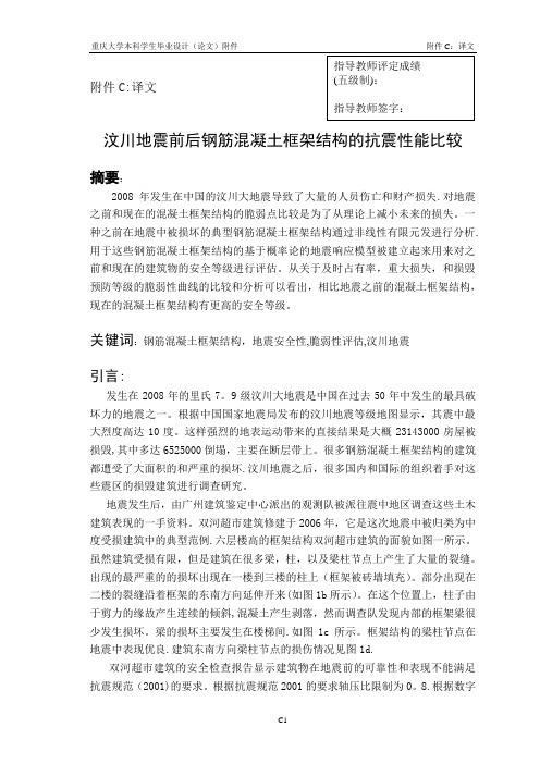
双河超市建筑修建于2006年,它是这次地震中被归类为中度受损建筑中的典型范例.六层楼高的框架结构双河超市建筑的面貌如图一所示。
虽然建筑受损有限,但是建筑在很多梁,柱,以及梁柱节点上产生了大量的裂缝。
出现的最严重的的损坏出现在一楼到三楼的柱上(框架被砖墙填充)。
部分出现在二楼的裂缝沿着框架的东南方向延伸开来(如图1b所示)。
在这个位置上,柱子由于剪力的缘故产生连续的倾斜,混凝土产生剥落,然而调查队发现内部的框架梁很少发生损坏。
梁的损坏主要发生在楼梯间.如图1c所示。
框架结构的梁柱节点在地震中表现优良.建筑东南方向梁柱节点的损伤情况见图1d.双河超市建筑的安全检查报告显示建筑物在地震前的可靠性和表现不能满足抗震规范(2001)的要求。
土木工程混凝土结构中英文对照外文翻译文献
中英文翻译Concrete structure reinforcement designAbstract:structure in the long-term natural environment and under the use environment's function, its function is weaken inevitably gradually, our structural engineering's duty not just must finish the building earlier period the project work, but must be able the science appraisal structure damage objective law and the degree, and adopts the effective method guarantee structure the security use, that the structure reinforcement will become an important work. What may foresee will be the 21st century, the human building also by the concrete structure, the steel structure, the bricking-up structure and so on primarily, the present stage I will think us in the structure reinforcement this aspect research should also take this as the main breakthrough direction.Key word:Concrete structure reinforcement bricking-up structure reinforcement steel structure reinforcement1 Concrete structure reinforcementConcrete structure's reinforcement divides into the directreinforcement and reinforces two kinds indirectly, when the design may act according to the actual condition and the operation requirements choice being suitable method and the necessary technology.1.1the direct reinforcement's general method1)Enlarges the section reinforcement lawAdds the concretes cast-in-place level in the reinforced concrete member in bending compression zone, may increase the section effective height, the expansion cross sectional area, thus enhances the component right section anti-curved, the oblique section anti-cuts ability and the section rigidity, plays the reinforcement reinforcement the role.In the suitable muscle scope, the concretes change curved the component right section supporting capacity increase along with the area of reinforcement and the intensity enhance. In the original component right section ratio of reinforcement not too high situation, increases the main reinforcement area to be possible to propose the plateau component right section anti-curved supporting capacity effectively. Is pulled in the section the area to add the cast-in-place concrete jacket to increase the component section, through new Canada partial and original component joint work, but enhances the componentsupporting capacity effectively, improvement normal operational performance.Enlarges the section reinforcement law construction craft simply, compatible, and has the mature design and the construction experience; Is suitable in Liang, the board, the column, the wall and the general structure concretes reinforcement; But scene construction's wet operating time is long, to produces has certain influence with the life, and after reinforcing the building clearance has certain reduction.2) Replacement concretes reinforcement lawThis law's merit with enlarges the method of sections to be close, and after reinforcing, does not affect building's clearance, but similar existence construction wet operating time long shortcoming; Is suitable somewhat low or has concretes carrier's and so on serious defect Liang, column in the compression zone concretes intensity reinforcement. 3) the caking outsourcing section reinforcement lawOutside the Baotou Steel Factory reinforcement is wraps in the section or the steel plate is reinforced component's outside, outside the Baotou Steel Factory reinforces reinforced concrete Liang to use the wet outsourcing law generally, namely uses the epoxy resinification to be in themilk and so on methods with to reinforce the section the construction commission to cake a whole, after the reinforcement component, because is pulled with the compressed steel cross sectional area large scale enhancement, therefore right section supporting capacity and section rigidity large scale enhancement.This law also said that the wet outside Baotou Steel Factory reinforcement law, the stress is reliable, the construction is simple, the scene work load is small, but is big with the steel quantity, and uses in above not suitably 600C in the non-protection's situation the high temperature place; Is suitable does not allow in the use obviously to increase the original component section size, but requests to sharpen its bearing capacity large scale the concrete structure reinforcement.4) Sticks the steel reinforcement lawOutside the reinforced concrete member in bending sticks the steel reinforcement is (right section is pulled in the component supporting capacity insufficient sector area, right section compression zone or oblique section) the superficial glue steel plate, like this may enhance is reinforcedcomponent's supporting capacity, and constructs conveniently.This law construction is fast, the scene not wet work or only has the plastering and so on few wet works, to producesis small with the life influence, and after reinforcing, is not remarkable to the original structure outward appearance and the original clearance affects, but the reinforcement effect is decided to a great extent by the gummy craft and the operational level; Is suitable in the withstanding static function, and isin the normal humidity environment to bend or the tension member reinforcement.5) Glue fibre reinforcement plastic reinforcement lawOutside pastes the textile fiber reinforcement is pastes with the cementing material the fibre reinforcement compound materials in is reinforced the component to pull the region, causes it with to reinforce the section joint work, achieves sharpens the component bearing capacity the goal. Besides has glues the steel plate similar merit, but also has anticorrosive muddy, bears moistly, does not increase the self-weight of structure nearly, durably, the maintenance cost low status merit, but needs special fire protection processing, is suitable in each kind of stress nature concrete structure component and the general construction.This law's good and bad points with enlarge the method of sections to be close; Is suitable reinforcement which is insufficient in the concrete structure component oblique section supporting capacity, or must exert the crosswise binding force to the compressional member the situation.6) Reeling lawThis law's good and bad points with enlarge the method of sections to be close; Is suitable reinforcement which is insufficient in the concrete structure component oblique section supporting capacity, or must exert the crosswise binding force to the compressional member the situation.7) Fang bolt anchor lawThis law is suitable in the concretes intensity rank is the C20~C60 concretes load-bearing member transformation, the reinforcement; It is not suitable for already the above structure which and the light quality structure makes decent seriously.1.2The indirect reinforcement's general method1)Pre-stressed reinforcement law(1)Thepre-stressed horizontal tension bar reinforces concretes member in bending,because the pre-stressed and increases the exterior load the combined action, in the tensionbar has the axial tension, this strength eccentric transmits on the component through the pole end anchor (, when tension bar and Liang board bottom surface close fitting, tension bar can look for tune together with component, this fashion has partial pressures to transmit directly for component bottom surface), has the eccentric compression function in the component, this function has overcome the bending moment which outside the part the load produces, reduced outside the load effect, thus sharpened component's anti-curved ability. At the same time, because the tension bar passes to component's pressure function, the component crack development can alleviate, the control, the oblique section anti-to cut the supporting capacity also along with it enhancement.As a result of the horizontal lifting stem's function, the original component's section stress characteristic by received bends turned the eccentric compression, therefore, after the reinforcement, component's supporting capacity was mainly decided in bends under the condition the original component's supporting capacity 。
钢筋混凝土结构文献综述范文

钢筋混凝土结构文献综述范文英文回答:Reinforced Concrete Structure Literature Review.Reinforced concrete (RC) is a composite material that combines the strength and durability of concrete with the tensile strength of steel reinforcement. RC structures are widely used in construction due to their versatility, durability, and cost-effectiveness.Properties of Reinforced Concrete.Compressive Strength: Concrete is strong in compression, but weak in tension.Tensile Strength: Steel reinforcement provides the tensile strength that concrete lacks.Bond Strength: The bond between concrete and steel iscrucial for the performance of RC structures.Durability: Concrete is resistant to fire, moisture, and weathering. Steel reinforcement can corrode if not properly protected.Design and Analysis of RC Structures.The design and analysis of RC structures involves considering various factors, including:Material properties (concrete strength, steel yield strength, bond strength)。
钢筋混凝土中英文对照外文翻译文献

中英文资料对照外文翻译目录1 中文翻译 (1)1.1钢筋混凝土 (1)1.2土方工程 (2)1.3结构的安全度 (3)2 外文翻译 (6)2.1 Reinforced Concrete (6)2.2 Earthwork (7)2.3 Safety of Structures (9)1 中文翻译1.1钢筋混凝土素混凝土是由水泥、水、细骨料、粗骨料(碎石或;卵石)、空气,通常还有其他外加剂等经过凝固硬化而成。
将可塑的混凝土拌合物注入到模板内,并将其捣实,然后进行养护,以加速水泥与水的水化反应,最后获得硬化的混凝土。
其最终制成品具有较高的抗压强度和较低的抗拉强度。
其抗拉强度约为抗压强度的十分之一。
因此,截面的受拉区必须配置抗拉钢筋和抗剪钢筋以增加钢筋混凝土构件中较弱的受拉区的强度。
由于钢筋混凝土截面在均质性上与标准的木材或钢的截面存在着差异,因此,需要对结构设计的基本原理进行修改。
将钢筋混凝土这种非均质截面的两种组成部分按一定比例适当布置,可以最好的利用这两种材料。
这一要求是可以达到的。
因混凝土由配料搅拌成湿拌合物,经过振捣并凝固硬化,可以做成任何一种需要的形状。
如果拌制混凝土的各种材料配合比恰当,则混凝土制成品的强度较高,经久耐用,配置钢筋后,可以作为任何结构体系的主要构件。
浇筑混凝土所需要的技术取决于即将浇筑的构件类型,诸如:柱、梁、墙、板、基础,大体积混凝土水坝或者继续延长已浇筑完毕并且已经凝固的混凝土等。
对于梁、柱、墙等构件,当模板清理干净后应该在其上涂油,钢筋表面的锈及其他有害物质也应该被清除干净。
浇筑基础前,应将坑底土夯实并用水浸湿6英寸,以免土壤从新浇的混凝土中吸收水分。
一般情况下,除使用混凝土泵浇筑外,混凝土都应在水平方向分层浇筑,并使用插入式或表面式高频电动振捣器捣实。
必须记住,过分的振捣将导致骨料离析和混凝土泌浆等现象,因而是有害的。
水泥的水化作用发生在有水分存在,而且气温在50°F以上的条件下。
土木工程 外文翻译 外文文献 英文文献
一、外文原文Talling building and Steel construction Although there have been many advancements in building construction technology in general. Spectacular archievements have been made in the design and construction of ultrahigh-rise buildings.The early development of high-rise buildings began with structural steel framing.Reinforced concrete and stressed-skin tube systems have since been economically and competitively used in a number of structures for both residential and commercial purposes.The high-rise buildings ranging from 50 to 110 stories that are being built all over the United States are the result of innovations and development of new structual systems.Greater height entails increased column and beam sizes to make buildings more rigid so that under wind load they will not sway beyond an acceptable limit.Excessive lateral sway may cause serious recurring damage to partitions,ceilings.and other architectural details. In addition,excessive sway may cause discomfort to the occupants of the building because their perception of such motion.Structural systems of reinforced concrete,as well as steel,take full advantage of inherent potential stiffness of the total building and therefore require additional stiffening to limit the sway.In a steel structure,for example,the economy can be defined in terms of the total average quantity of steel per square foot of floor area of the building.Curve A in Fig .1 represents the average unit weight of a conventional frame with increasing numbers of stories. Curve B represents the average steel weight if the frame is protected from all lateral loads. The gap between the upper boundary and the lower boundary represents the premium for height for the traditional column-and-beam frame.Structural engineers have developed structural systems with a view to eliminating this premium.Systems in steel. Tall buildings in steel developed as a result ofseveral types of structural innovations. The innovations have been applied to the construction of both office and apartment buildings.Frame with rigid belt trusses. In order to tie the exterior columns of a frame structure to the interior vertical trusses,a system of rigid belt trusses at mid-height and at the top of the building may be used. A good example of this system is the First Wisconsin Bank Building(1974) in Milwaukee.Framed tube. The maximum efficiency of the total structure of a tall building, for both strength and stiffness,to resist wind load can be achieved only if all column element can be connected to each other in such a way that the entire building acts as a hollow tube or rigid box in projecting out of the ground. This particular structural system was probably used for the first time in the 43-story reinforced concrete DeWitt Chestnut Apartment Building in Chicago. The most significant use of this system is in the twin structural steel towers of the 110-story World Trade Center building in New York Column-diagonal truss tube. The exterior columns of a building can be spaced reasonably far apart and yet be made to work together as a tube by connecting them with diagonal members interesting at the centre line of the columns and beams. This simple yet extremely efficient system was used for the first time on the John Hancock Centre in Chicago, using as much steel as is normally needed for a traditional 40-story building.Bundled tube. With the continuing need for larger and taller buildings, the framed tube or the column-diagonal truss tube may be used in a bundled form to create larger tube envelopes while maintaining high efficiency. The 110-story Sears Roebuck Headquarters Building in Chicago has nine tube, bundled at the base of the building in three rows. Some of these individual tubes terminate at different heights of the building, demonstrating the unlimited architectural possibilities of this latest structural concept. The Sears tower, at a height of 1450 ft(442m), is the world’s tallest building.Stressed-skin tube system. The tube structural system was developed for improving the resistance to lateral forces (wind and earthquake) and thecontrol of drift (lateral building movement ) in high-rise building. The stressed-skin tube takes the tube system a step further. The development of the stressed-skin tube utilizes the façade of the building as a structural element which acts with the framed tube, thus providing an efficient way of resisting lateral loads in high-rise buildings, and resulting in cost-effective column-free interior space with a high ratio of net to gross floor area.Because of the contribution of the stressed-skin façade, the framed members of the tube require less mass, and are thus lighter and less expensive. All the typical columns and spandrel beams are standard rolled shapes,minimizing the use and cost of special built-up members. The depth requirement for the perimeter spandrel beams is also reduced, and the need for upset beams above floors, which would encroach on valuable space, is minimized. The structural system has been used on the 54-story One Mellon Bank Center in Pittburgh.Systems in concrete. While tall buildings constructed of steel had an early start, development of tall buildings of reinforced concrete progressed at a fast enough rate to provide a competitive chanllenge to structural steel systems for both office and apartment buildings.Framed tube. As discussed above, the first framed tube concept for tall buildings was used for the 43-story DeWitt Chestnut Apartment Building. In this building ,exterior columns were spaced at 5.5ft (1.68m) centers, and interior columns were used as needed to support the 8-in . -thick (20-m) flat-plate concrete slabs.Tube in tube. Another system in reinforced concrete for office buildings combines the traditional shear wall construction with an exterior framed tube. The system consists of an outer framed tube of very closely spaced columns and an interior rigid shear wall tube enclosing the central service area. The system known as the tube-in-tube system , made it possible to design the world’s present tallest (714ft or 218m)lightweight concrete bu ilding( the 52-story One Shell Plaza Building in Houston) for the unit price of a traditional shear wall structure of only 35 stories.Systems combining both concrete and steel have also been developed, an examle of which is the composite system developed by skidmore, Owings &Merril in which an exterior closely spaced framed tube in concrete envelops an interior steel framing, thereby combining the advantages of both reinforced concrete and structural steel systems. The 52-story One Shell Square Building in New Orleans is based on this system.Steel construction refers to a broad range of building construction in which steel plays the leading role. Most steel construction consists of large-scale buildings or engineering works, with the steel generally in the form of beams, girders, bars, plates, and other members shaped through the hot-rolled process. Despite the increased use of other materials, steel construction remained a major outlet for the steel industries of the U.S, U.K, U.S.S.R, Japan, West German, France, and other steel producers in the 1970s.二、原文翻译高层结构与钢结构近年来,尽管一般的建筑结构设计取得了很大的进步,但是取得显著成绩的还要属超高层建筑结构设计。
土木工程专业钢筋混凝土结构设计毕业论文外文文献翻译及原文
毕业设计(论文)外文文献翻译文献、资料中文题目:钢筋混凝土结构设计文献、资料英文题目:DESIGN OF REINFORCED CONCRETE STRUCTURES 文献、资料来源:文献、资料发表(出版)日期:院(部):专业:土木工程班级:姓名:学号:指导教师:翻译日期: 2017.02.14毕业设计(论文)外文参考资料及译文译文题目:DESIGN OF REINFORCED CONCRETE STRUCTURES原文:DESIGN OF REINFORCED CONCRETESTRUCTURES1. BASIC CONCERPTS AND CHARACERACTERISTICS OF REINFORCED CONCRETEPlain concrete is formed from hardened mixture of cement, water , fine aggregate , coarse aggregate (crushed stone or gravel ) , air and often other admixtures . The plastic mix is placed and consolidated in the formwork, then cured to accelerate of the chemical hydration of hen cement mix and results in a hardened concrete. It is generally known that concrete has high compressive strength and low resistance to tension. Its tensile strength is approximatelyone-tenth of its compressive strength. Consequently, tensile reinforcement in the tension zone has to be provided to supplement the tensile strength of the reinforced concrete section.For example, a plain concrete beam under a uniformly distributed load q is shown in Fig .1.1(a), when the distributed load increases and reaches a value q=1.37KN/m , the tensile region at the mid-span will be cracked and the beam will fail suddenly . A reinforced concrete beam if the same size but has to steel reinforcing bars (2φ16) embedded at the bottom under a uniformly distributed load q is shown in Fig.1.1(b). The reinforcing bars take up the tension there after the concrete is cracked. When the load q is increased, the width of the cracks, the deflection and thestress of steel bars will increase . When the steel approaches the yielding stress ƒy , thedeflection and the cracked width are so large offering some warning that the compression zone . The failure load q=9.31KN/m, is approximately 6.8 times that for the plain concrete beam.Concrete and reinforcement can work together because there is a sufficiently strong bond between the two materials, there are no relative movements of the bars and the surrounding concrete cracking. The thermal expansion coefficients of the two materials are 1.2×10⁻⁵K-1 for steel and 1.0×10⁻⁵~1.5×10⁻⁵K-1 for concrete .Generally speaking, reinforced structure possess following features :Durability .With the reinforcing steel protected by the concrete , reinforced concreteFig.1.1Plain concrete beam and reinforced concrete beamIs perhaps one of the most durable materials for construction .It does not rot rust , and is not vulnerable to efflorescence .(2)Fire resistance .Both concrete an steel are not inflammable materials .They would not be affected by fire below the temperature of 200℃when there is a moderate amount of concrete cover giving sufficient thermal insulation to the embedded reinforcement bars.(3)High stiffness .Most reinforced concrete structures have comparatively large cross sections .As concrete has high modulus of elasticity, reinforced concrete structures are usuallystiffer than structures of other materials, thus they are less prone to large deformations, This property also makes the reinforced concrete less adaptable to situations requiring certainflexibility, such as high-rise buildings under seismic load, and particular provisions have to be made if reinforced concrete is used.(b)Reinfoced concrete beam(4)Locally available resources. It is always possible to make use of the local resources of labour and materials such as fine and coarse aggregates. Only cement and reinforcement need to be brought in from outside provinces.(5)Cost effective. Comparing with steel structures, reinforced concrete structures are cheaper.(6)Large dead mass, The density of reinforced concrete may reach2400~2500kg/pare with structures of other materials, reinforced concrete structures generally have a heavy dead mass. However, this may be not always disadvantageous, particularly for those structures which rely on heavy dead weight to maintain stability, such as gravity dam and other retaining structure. The development and use of light weight aggregate have to a certain extent make concrete structure lighter.(7)Long curing period.. It normally takes a curing period of 28 day under specified conditions for concrete to acquire its full nominal strength. This makes the progress of reinforced concrete structure construction subject to seasonal climate. The development of factory prefabricated members and investment in metal formwork also reduce the consumption of timber formwork materials.(8)Easily cracked. Concrete is weak in tension and is easily cracked in the tension zone. Reinforcing bars are provided not to prevent the concrete from cracking but to take up the tensile force. So most of the reinforced concrete structure in service is behaving in a cracked state. This is an inherent is subjected to a compressive force before working load is applied. Thus the compressed concrete can take up some tension from the load.2. HISTOEICAL DEVELPPMENT OF CONCRETE STRUCTUREAlthough concrete and its cementitious(volcanic) constituents, such as pozzolanic ash, have been used since the days of Greek, the Romans, and possibly earlier ancient civilization, the use of reinforced concrete for construction purpose is a relatively recent event, In 1801, F. Concrete published his statement of principles of construction, recognizing the weakness if concrete in tension, The beginning of reinforced concrete is generally attributed to Frenchman J. L. Lambot, who in 1850 constructed, for the first time, a small boat with concrete for exhibition in the 1855 World’s Fair in Paris. In England, W. B. Wilkinson registered a patent for reinforced concrete l=floor slab in 1854.J.Monier, a French gardener used metal frames as reinforcement to make garden plant containers in 1867. Before 1870, Monier had taken a series of patents to make reinforcedconcrete pipes, slabs, and arches. But Monier had no knowledge of the working principle of this new material, he placed the reinforcement at the mid-depth of his wares. Then little construction was done in reinforced concrete. It is until 1887, when the German engineers Wayss and Bauschinger proposed to place the reinforcement in the tension zone, the use of reinforced concrete as a material of construction began to spread rapidly. In1906, C. A. P. Turner developed the first flat slab without beams.Before the early twenties of 20th century, reinforced concrete went through the initial stage of its development, Considerable progress occurred in the field such that by 1910 the German Committee for Reinforced Concrete, the Austrian Concrete Committee, the American Concrete Institute, and the British Concrete Institute were established. Various structural elements, such as beams, slabs, columns, frames, arches, footings, etc. were developed using this material. However, the strength of concrete and that of reinforcing bars were still very low. The common strength of concrete at the beginning of 20th century was about 15MPa in compression, and the tensile strength of steel bars was about 200MPa. The elements were designed along the allowable stresses which was an extension of the principles in strength of materials.By the late twenties, reinforced concrete entered a new stage of development. Many buildings, bridges, liquid containers, thin shells and prefabricated members of reinforced concrete were concrete were constructed by 1920. The era of linear and circular prestressing began.. Reinforced concrete, because of its low cost and easy availability, has become the staple material of construction all over the world. Up to now, the quality of concrete has been greatly improved and the range of its utility has been expanded. The design approach has also been innovative to giving the new role for reinforced concrete is to play in the world of construction.The concrete commonly used today has a compressive strength of 20~40MPa. For concrete used in pre-stressed concrete the compressive strength may be as high as 60~80MPa. The reinforcing bars commonly used today has a tensile strength of 400MPa, and the ultimate tensile strength of prestressing wire may reach 1570~1860Pa. The development of high strength concrete makes it possible for reinforced concrete to be used in high-rise buildings, off-shore structures, pressure vessels, etc. In order to reduce the dead weight of concrete structures, various kinds of light concrete have been developed with a density of 1400~1800kg/m3. With a compressive strength of 50MPa, light weight concrete may be used in load bearing structures. One of the best examples is the gymnasium of the University of Illinois which has a span of 122m and is constructed of concrete with a density of 1700kg/m3. Another example is the two 20-story apartment houses at the Xi-Bian-Men in Beijing. The walls of these two buildings are light weight concrete with a density of 1800kg/m3.The tallest reinforced concrete building in the world today is the 76-story Water Tower Building in Chicago with a height of 262m. The tallest reinforced concrete building in China today is the 63-story International Trade Center in GuangZhou with a height a height of 200m. The tallest reinforced concrete construction in the world is the 549m high International Television Tower in Toronto, Canada. He prestressed concrete T-section simply supported beam bridge over the Yellow River in Luoyang has 67 spans and the standard span length is 50m.In the design of reinforced concrete structures, limit state design concept has replaced the old allowable stresses principle. Reliability analysis based on the probability theory has very recently been introduced putting the limit state design on a sound theoretical foundation. Elastic-plastic analysis of continuous beams is established and is accepted in most of the design codes. Finite element analysis is extensively used in the design of reinforced concrete structures and non-linear behavior of concrete is taken into consideration. Recent earthquake disasters prompted the research in the seismic resistant reinforced of concrete structures. Significant results have been accumulated.3. SPECIAL FEATURES OF THE COURSEReinforced concrete is a widely used material for construction. Hence, graduates of every civil engineering program must have, as a minimum requirement, a basic understanding of the fundamentals of reinforced concrete.The course of Reinforced Concrete Design requires the prerequisite of Engineering Mechanics, Strength of Materials, and some if not all, of Theory of Structures, In all these courses, with the exception of Strength of Materials to some extent, a structure is treated of in the abstract. For instance, in the theory of rigid frame analysis, all members have an abstract EI/l value, regardless of what the act value may be. But the theory of reinforced concrete is different, it deals with specific materials, concrete and steel. The values of most parameters must be determined by experiments and can no more be regarded as some abstract. Additionally, due to the low tensile strength of concrete, the reinforced concrete members usually work with cracks, some of the parameters such as the elastic modulus I of concrete and the inertia I of section are variable with the loads.The theory of reinforced concrete is relatively young. Although great progress has been made, the theory is still empirical in nature in stead of rational. Many formulas can not be derived from a few propositions, and may cause some difficulties for students. Besides, due to the difference in practice in different countries, most countries base their design methods on their own experience and experimental results. Consequently, what one learns in one country may be different in another country. Besides, the theory is still in a stage of rapid。
土木工程论文外语翻译 译文

公开于土木工程学报2015, 5, 203-2132015年六月发表于网上/journal/ojce/10.4236/ojce.2015.52020通过静力弹塑性分析建筑结构对钢筋混凝土结构抗震性能的影响Yasser Alashker1, Sohaib Nazar2, Mohamed Ismaiel2,31结构工程系,工程学院,扎加齐格大学,扎加齐格,埃及2工程学院,哈立德皇家学院,阿布哈,沙特阿拉伯王国3开罗大学,开罗,埃及邮箱: **********************2015年4月6日接收;2015年5月19日接受;2015年5月22日出版版权©2015年作者和科学研究出版公司本工作获得国际知识共享归属组织许可(CC BY)。
/licenses/by/4.0/摘要在最近的地震中,混凝土结构受到严重破坏或倒塌,这对现有建筑的抗震性提出质疑。
这些现有的钢筋混凝土建筑需要评估来确定抵抗地震荷载的能力。
建筑在地震中的表现取决于它的整体形状,大小和几何形状。
建筑抗震设计的常规方法是取决于为建筑提供足以抵抗一定等级地震破坏的强度、刚度和塑性变形能力。
这通常是通过选择一个合适的建筑结构和仔细设计的结构部件。
在这个研究中,在同一地区同一高度用三个不同的方案的非线性静力弹塑性分析来评估三个建筑物的抗震性能。
这个方法确定建筑基础的抗剪能力和建筑在不同强度的地震力作用下每一部分的性能水平。
从位移、基底剪力和塑性铰模式等方面分析了不同方案对建筑物抗震性的影响。
关键词静力弹塑性分析,抗震性能,基地剪力,建筑结构1.前言本文引用:Alashker, Y., Nazar, S. and Ismaiel, M. (2015)通过静力弹塑性分析钢筋混凝土建筑物的抗震性能来影响建筑结构。
公开于土木工程学报 2015, 5, 203-213/10.4236/ojce.2015.52020地震是地球表面的振动,伴随着地壳中的能量突然释放。
土木工程专业Reinforced-Concrete钢筋混凝土大学毕业论文外文文献翻译及原文
毕业设计(论文)外文文献翻译文献、资料中文题目:钢筋混凝土文献、资料英文题目:Reinforced Concrete文献、资料来源: __________________________ 文献、资料发表(出版)日期: _____________________ 院(部):专业:_________________________________________ 班级:_________________________________________ 姓名:_________________________________________ 学号:_________________________________________ 指导教师:翻译日期:2017.02.14外文文献翻译Reinforced ConcreteCon crete and rein forced con crete are used as build ing materials in every coun try. In many, in clud ing the Un ited States and Can ada, rein forced con crete is a dominant structural material in engin eered con structi on.The uni versal n ature of rein forced con crete con structi on stems from the wide availability of rei nforci ng bars and the con stitue nts of con crete, gravel, sand, and cement, the relatively simple skills required in con crete con structi on, and the economy of rein forced con crete compared to other forms of con structi on. Con crete and rein forced con crete are used in bridges, build ings of all sorts un dergro und structures, water tan ks, televisi on towers, offshore oil explorati on and product ion structures, dams, and eve n in ships.Rein forced con crete structures may be cast-i n-place con crete, con structed in their fin al locatio n, or they may be precast con crete produced in a factory and erected at the con structi on site. Con crete structures maybe severe and functional in design, or the shape and layout and be whimsical and artistic. Few other buildi ng materials off the architect and engin eer such versatility and scope.Con crete is stro ng in compressi on but weak in tension. As a result, cracks develop whe never loads, or restrai ned shri nkage of temperature changes, give rise to tensile stresses in excess of the tensile strengthof the con crete. In a pla in con crete beam, the mome nts about the n eutral axis due to applied loads are resisted by an internal tension-compression couple involving tension in the concrete. Such a beamfails very suddenly and completely when the first crack forms. In a reinforced concrete beam, steel bars are embedded in the con crete in such a way that the tension forces n eeded for mome nt equilibrium after the con crete cracks can be developed in the bars.The con structi on of a rein forced con crete member invo Ives build ing a from of mold in the shape of the member being built. The form must be strong eno ugh to support both the weight and hydrostatic pressure of the wet concrete, and any forces applied to it by workers, concrete buggies,wind, and so on. The reinforcement is placed in this form and held in place duri ng the con cret ing operati on. After the con crete has harde ned, the forms are removed. As the forms are removed, props of shores are in stalled to support the weight of the con crete un til it has reached sufficie nt stre ngth to support the loadsby itself.The designer must proportion a concrete memberfor adequate strengthto resist the loads and adequate stiffness to prevent excessive deflecti ons. In beam must be proporti oned sothat it can be con structed.For example, the reinforcement must be detailed so that it can beassembled in the field, and since the con crete is placed in the form after the rei nforceme nt is inplace, the con crete must be ableto flow around,between, andpast the reinforcement to fill all parts of the form completely.The choice of whether a structure should be built of concrete, steel, masonry, or timber depends on the availability of materials and on a number of value decisions.The choice of structural system is made by thearchitect of engineer early in the design, based on the followingcon siderati ons:1. Economy. Freque ntly, the foremost con sideratio n is the overall const of the structure. This is, of course, a fun cti on of the costs ofthe materials and the labor necessary to erect them. Frequently, however, the overall cost is affected as much or more by the overall con structi on time since the con tractor and owner must borrow or otherwise allocate money to carry out the con struct ion and will not receive a retur n on this investment until the building is ready for occupancy. In a typical large apartme nt of commercial project, the cost of con struct ion financing willbe a significant fraction of the total cost. As a result, financial savings due to rapid con structi on may more tha n offset in creased material costs. For this reas on, any measures the desig ner can take to sta ndardize the desig n and forming will gen erally pay off in reduced overall costs.In many cases the Ion g-term economy of the structure may be more importa nt tha n the first cost. As a result, maintenance and durability are importa nt con siderati on.2. Suitability of material for architectural and structural function.A rein forced con crete system freque ntly allows the desig ner to comb ine the architectural and structural functions. Con crete has the adva ntage that it is placed in a plastic con diti on and is give n the desired shapeand texture by meansof the forms and the finishing techniques. This allows such elements ad flat plates or other types of slabs to serve as load-bearingelements while providing the finished floor and / or ceiling surfaces. Similarly, rein forced con crete walls can providearchitecturally attractive surfaces in addition to having the ability to resist gravity, wind, or seismic loads. Fin ally, the choice of size of shape is governed by the designer and not by the availability of standard manu factured members.3. Fire resista nee. The structure in a buildi ng must withsta nd theeffects of a fire and rema in sta nding while the build ing is evacuated and the fire is exti nguished. A con crete buildi ng in here ntly has a 1- to 3-hour fire rat ing without special fireproofi ng or other details. Structural steel or timber build ings must be fireproofed to atta in similar fire ratin gs.4. Low maintenan ce. Con crete members in here ntly require less maintenance than do structural steel or timber members. This is particularly true if den se, air-e ntrained con crete has bee n used forsurfaces exposed to the atmosphere, and if care has bee n take n in the desig n to provide adequate drain age off and away from the structure. Special precauti ons must be take n for con crete exposed to salts such as deici ng chemicals.5. Availability of materials. Sand, gravel, ceme nt, and con cretemixi ng facilities are very widely available, and rein forci ng steel canbe tran sported to most job sites more easily tha n can structural steel. As a result, re in forced con crete is freque ntly used in remote areas.On the other hand, there are a nu mber of factors that may cause one to selecta material other tha n rein forced con crete. These in clude:1. Low tensile strength. The tensile strength concrete is much lower than its compressive strength ( about 1/10 ), and hence concrete is subject to crack ing. In structural uses this is overcome by using rei nforceme nt to carry ten sile forces and limit crack widths to with in acceptable values. Un less care is take n in desig n and con struct ion, however, these cracks maybe unsightly or mayallow penetration of water. Wherthis occurs, water or chemicals such as road deicing salts may cause deterioration or stai ning of the con crete. Special desig n details are required in such cases. In the case of water-retai ning structures, special details and /of prestress ing are required to preve nt leakage.2. Forms and shori ng. The con structi on of a cast-i n-place structureinvo Ives three steps not encoun tered in the con struct ion of steel or timberstructures. These are ( a ) the con struct ion of the forms, ( b ) the removal of these forms, and (c) propp ing or shori ng the new con crete to support its weight until itsstrength is adequate. Each of these steps invoIves labor and / or materials, which are not necessary with other forms of con structi on.3. Relatively low strength per unit of weight for volume. Thecompressive strength of concrete is roughly 5 to 10%that of steel, while its unit den sity is roughly 30% that of steel. As a result, a con cretestructure requires a larger volume and a greater weight of material than does acomparable steel structure. As a result, Iong-span structures are ofte n built from steel.4. Time-depe ndent volume cha nges. Both con crete and steelundergo-approximately the same amount of thermal expansionandcon tracti on. Because there is less mass of steel to be heated or cooled, andbecause steel is a better con crete, a steel structure is gen erallyaffected by temperature cha nges to a greater exte nt tha n is a con crete structure.On the other hand, con crete un dergoes fryi ng shri nkage, which, if restrained, may cause deflections or cracking. Furthermore, deflecti ons will tend to in crease with time, possibly doubli ng, due to creep of the con crete un der susta ined loads.In almost every branch of civil extensiveuse is made of reinforced foundations.Engineers and architects reinforced con crete desig n throughout theirprofessi onal careers. Muchof this text is directly concerned with the behavior and proporti oningof components that makeup typical reinforced concrete structures-beams, colu mns, and slabs. Once the behavior of these in dividual eleme nts is un derstood, the desig ner will have the backgro und to an alyze and desig n a wide range of complex structures, such as foun datio ns, buildi ngs, and bridges, composed of these eleme nts.Si nee rei nforced concrete is a no homogeneous material that creeps, shri nks,and cracks, its stresses cannot be accurately predicted by the traditi onal equati ons derived in a course in stre ngth of materials forhomoge neous elastic materials. Much of rein forced con crete desig n in thereforeempirical, i.e., design equations and design methods are based on experime ntal and engineering and architecture con crete for structures and requires basic knowledge oftime-proved results in stead of being derived exclusively from theoretical formulati ons.A thorough un dersta nding of the behavior of rein forced con crete will allow the desig ner to con vert an otherwise brittle material into tough ductile structural elements and thereby take advantage of concrete ' s desirable characteristics, its high compressive stre ngth, its fire resista nee, and its durability.Concrete, a stone like material, is madeby mixing cement, water, fine aggregate ( often sand ), coarse aggregate, and frequently other additives (that modify properties ) into a workable mixture. In its un harde ned or plastic state, concrete can be placed in forms to produce a large variety of structural eleme nts. Although the harde ned con crete by itself, i.e., without any rein forceme nt, is stro ng in compressi on, it lacks ten sile stre ngth and therefore cracks easily. Because unrein forced con crete is brittle, it cannot undergo large deformations under load and fails sudde nly-without warni ng. The additi on fo steel rein forceme nt to the con crete reduces the n egative effects of its two prin cipal in here nt weaknesses, its susceptibility to cracking and its brittleness. Whenthe rein forceme nt is stro ngly bon ded to the con crete, a strong, stiff, and ductile con struct ion material is produced. This material, calledrei nforced con crete, is used exte nsively to con struct foun dati ons,structural frames, storage takes, shell roofs, highways, walls, dams, canals, and innumerable other structures and building products. Twoother characteristics of concrete that are present even when concrete is rein forced are shri nkage and creep, but the n egative effects of these properties can be mitigated by careful desig n.A code is a set tech ni cal specificati ons and sta ndards that con trol importa nt details of desig n and con struct ion. The purpose of codes it produce structures so that the public will be protected from poor of in adequate and con struct ion.Two types f coeds exist. One type, called a structural code, is orig in ated and con trolled by specialists whoare concerned with the proper use of a specific material or who are invo Ived with the safe desig n of a particular class of structures.The sec ond type of code, called a build ing code, is established to cover con struct ion in a give n region, ofte n a city or a state. The objective of a build ing code is also to protect the public by acco un ti ng for the in flue nee of the local en vir onmen tal con diti ons on con structi on. For example, local authorities may specifyadditional provisions toaccount for such regional conditions as earthquake, heavy snow, ortorn ados. Nati onal structural codes gen rally are in corporated into local build ing codes.The America n Con crete In stitute ( ACI ) Buildi ng Code coveri ng the desig n of rein forced con crete build in gs. It contains provisi ons coveri ngall aspects of re in forced con crete manu facture, desig n, and con structi on. It includes specifications on quality of materials, details on mixing andplacing concrete, design assumptions for the analysis of continuous structures, and equati ons for proporti oning members for desig n forces.All structures must be proporti oned so they will not fail or deform excessively un der any possible con diti on of service. Therefore it is important that an engineer use great care in anticipating all the probable loads to which a structure will be subjected duri ng its lifetime.Although the desig n of most members is con trolled typically by dead and live load acting simultaneously, consideration must also be given tothe forces produced by wind, impact, shrinkage, temperature change, creep and support settleme nts, earthquake, and so forth.The load associated with the weight of the structure itself and its perma nent comp onents is called the dead load. The dead load of con crete members, which is substantial, should never be neglected in design computations. The exact magnitude of the dead load is not known accurately un til members have bee n sized. Since some figure for the dead load must be used in computations to size the members, its magnitude must be estimated at first. After a structure has been analyzed, the memberssized, and architectural details completed, the dead load can be computed more accurately. If the computed dead load is approximately equal to the initial estimate of its value ( or slightly less ), the design is complete,but if a significant differenee exists between the computed and estimated values of dead weight, the computations should be revised using an improved value of dead load. An accurate estimate of dead load is particularly importa nt whe n spa ns are long, say over 75 ft ( 22.9 m ),because dead load con stitutes a major porti on of the desig n load.Live loads associated with building use are specific items of equipme nt and occupa nts in a certa in area of a build ing, buildi ng codes specify values of un iform live for which members are to be desig ned.After the structure has bee n sized for vertical load, it is checkedfor wi nd in comb in ati on with dead and live load as specified in the code. Windloads do not usually con trol the size of members in buildi ng lessthan 16 to 18 stories, but for tall buildings wind loads becomesignificant and cause large forces to develop in the structures. Under these conditions economycan be achieved only by selecting a structural system that is able to tran sfer horiz on tal loads into the ground efficie ntly.钢筋混凝土在每一个国家,混凝土及钢筋混凝土都被用来作为建筑材料。
土木工程混凝土论文中英文资料外文翻译文献

土木工程混凝土论文中英文资料外文翻译文献外文资料STUDIES ON IMPACT STRENGTH OF CONCRETESUBJECTED TO SUSTAINEDELEVATED TEMPERATUREConcrete has a remarkable fire resisting properties. Damage in concrete due to fire depends on a great extent on the intensity and duration of fire. Spalling cracking during heating are common concrete behaviour observed in the investigation of the fire affected structures. Plenty of literature is available on the studies of concrete based on time temperature cures. In power, oil sectorsand nuclear reactors concrete is exposed to high temperature for considerable period of time. These effects can be reckoned as exposure to sustained elevated temperature. The sustained elevated temperature may be varying from a few hours to a number of years depending upon practical condition of exposures. The knowledge on properties under such conditions is also of prime importance apart from the structures subjected to high intensity fire. Impact studies of structure subjected to sustained elevated temperature becomes more important as it involves sensitive structures which is more prone to attacks and accidents. In this paper impact studies on concrete subjected to sustained elevated temperature has been discussed. Experiments have been conducted on 180 specimens along with 180 companion cube specimens. The temperatures of 100°C, 200°C and 300°C for a duration of exposure of 2 hours 4 hours and 6 hours has been considered in the experiments. The results are logically analyzed and concluded.1. INTRODUCTIONThe remarkable property of concrete to resist the fire reduces the damage in a concrete structure whenever there is an accidental fire. In most of the cases the concrete remains intact with minor damages only. The reason being low thermal conductivity of concrete at higher temperatures and hence limiting the depth of penetration of firedamage. But when the concrete is subjected to high temperature for long duration the deterioration of concrete takes place. Hence it is essential to understand the strength and deformation characteristics of concrete subjected to temperature for long duration. In this paper an attempt has been made to study the variation in Impact Strength of concrete when subjected to a temperature range 100oC, 200oC and 300oC sustained for a period of 2 hrs, 4 hrs and 6 hrs.The review of the literature shows that a lot of research work [1 – 3] has taken place on the effect of elevated temperature on concrete. All these studies are based on time –temperature curves. Hence an attempt has been made to study the effect of sustained elevated temperature on impact strength of concrete and the results are compared with the compressive strength. The experimental programme has been planned for unstressed residual strength test based on the available facilities. Residual strength is the strength of heated and subsequently cooled concrete specimens expressed as percentage of the strength of unheated specimens.2. EXPERIMENTAL INVESTIGATION2.1. TEST SPECIMEN AND MATERIALSA total of 180 specimens were tested in the present study along with 180 companion cubes. An electric oven capable of reaching a maximum temperature of 300oC has been used for investigation. Fine and coarse aggregates conforming to IS383 has been used to prepare the specimen with mix proportions M1 = 1:2.1:3.95 w/c = 0.58, M2 = 1:1.15:3.56 w/c = 0.53, M3 = 1:0.8:2.4 w/c = 0.4.2.2 TEST VARIABLESThe effects of the following variables were studied.2.2.1 Size sSize of Impact Strength Test Specimen was 150 mm dial and 64 mm thickness and size of companion cube 150 x 150 x 150 mm.2.2.2 Maximum TemperatureIn addition to room temperature, the effect of three different temperatures (100oC, 200oC and 300oC) on the compressive strength was investigated.2.2.3 Exposure Time at Maximum TemperatureThree different exposure times were used to investigate the influence of heat on compressive strength; they are 2 hrs, 4 hrs and 6 hrs.2.2.4 Cooling MethodSpecimens were cooled in air to room temperature.3. TEST PROCEDUREAll the specimens were cast in steel moulds as per IS516 and each layer was compacted. Specimens were then kept in their moulds for 24 hours after which they were decoupled and placed into a curing tank until 28 days. After which the specimens were removed and were allowed to dry in room temperature. These specimens were kept in the oven and the required target temperature was set. Depending on the number of specimen kept inside the oven the time taken to reach the steady state was found to vary. After the steady state was reached the specimens were subjected to predetermined steady duration at the end of which the specimens are cooled to room temperature and tested.ACI drop weight impact strength test was adopted. This is the simplest method for evaluating impact resistance of concrete. The size of the specimen is 150 mm dial and 64 mm thickness. The disc specimens were prepared using steel moulds cured and heated and cooled as. This consists of a standard manually operated 4.54 kg hammer with 457 mm drop. A 64 mm hardened steel ball and a flat base plate with positioning bracket and lugs. The specimen is placed between the four guides pieces (lugs) located 4.8 mm away from the sample. A frame (positioning bracket) is then built in order to target the steel ball at the centre of concrete disc. The disc is coated at the bottom with a thin layer of petroleum jelly or heavy grease to reduce the friction between the specimen and base plate. The bottom part of the hammer unit was placed with its base upon the steel ball and the load was applied by dropping weight repeatedly. The loading was continued until the disc failed and opened up such that it touched three of the four positioning lugs. The number of blows that caused this condition is recorded as the failure strength. The companion cubes were tested for cube compression strength (fake).4. ANALYSIS AND RESULTS4.1 RESIDUAL COMPRESSIVE STRENGTH VS. TEMPERATUREFrom Table 1, at 100°C sustained elevated temperature it is seen that the residual strength of air cooled specimens of mixes M1, M2 and M3 has increased in strength 114% for M1 mix, 109% for M2 mix and 111% for M3 mix for 6 hours duration of exposure. When the sustained elevated temperature is to 200°C for air cooled specimens there is a decrease in strength up to 910% approximately for M1 mix for a duration of 6 hours, but in case of M2 mix it is 82% and for M3 mix it is 63% maximum for 6 hours duration of exposure. When the concrete mixes M1, M2 and M3 are exposed to 300°C sustained temperature there is a reduction in strength up to 78% for M1 mix for 6 hour duration of exposure.4.2 RESIDUAL COMPRESSIVE STRENGTH VS DURATION OF EXPOSUREFrom Table 1, result shows that heating up to 100°C for 2 hours and 4 hours, the residual strength of mix M1 has decreased where as the residual strength of mix M2 and M3 has increased. The residual strength is further increased for 6 hours duration of exposure in all the three mixes M1, M2 and M3 even beyond the strength at room temperature. When the specimens of mixes M1, M2 and M3 are exposed to 200°C for 2,4 and 6 hours of duration, it is observed that the residual strength has decreased below the room temperature and has reached 92% for M1 mix, 82 and 73% for M2 and M3 mix respectively. Concrete cubes of mixes M1, M2 and M3 when subjected to 300°C temperature for 2,4 and 6 hours the residual strength for mix M1 reduces to 92% for 2 hours up to 78% for six hours duration of exposure, for M2 mix 90% for 2 hours duration of exposure up to 76% for six hour duration of exposure, for M3 mix 88% up to 68% between 2 and 6 hours of duration of exposure.5. IMPACT STRENGTH OF CONCRETE5.1 RESIDUAL IMPACT STRENGTH VS TEMPERATUREFrom the table 1, it can be observed that for the sustained elevated temperature of 100°C the residual impact strength of all the specimens reduces and vary between 20 and 50% for mix M1, 15 to 40% for mix M2 and M3. When the sustained elevated temperature is 200°C the residual impact strength of all the mixes further decreases. The reduction is around 60-70% for mix M1, 55 to 65% for M2 and M3 mix. When the sustained elevated temperature is 300°C it is observed that the residual impact strength reduces further and vary between 85 and 70% for mix M1 and 85 to 90% for mix M2 and mix M3.5.2 RESIDUAL IMPACT STRENGTH VS DURATION OF EXPOSUREFrom the Table 1 and Figures 1 to 3, it can be observed that there is a reduction in impact strength when the sustained elevated temperature is 100°C for 2 hrs, 4 hrs and 6 hrs, and its range is 15 to 50% for all the mixes M1, M2 and M3. The influence of duration of exposure is higher for mix M1 which decreases more rapidly as compared to mix M2 and mix M3 for the same duration of exposure. When the specimens are subjected to sustained elevated temperature of 200°C for 2,4 and 6 hour of duration, further reduction in residual impact strength is observed as compared to at 100°C. The reduction is in the range of 55-70% for all the mixes. The six hour duration of exposure has a greater influence on the residual impact strength of concrete. When the sustained elevated temperature is 300°C for 2,4 and 6 hours duration of exposure the residualimpact strength reduces. It can be seen that both temperature and duration of exposure have a very high influence on the residual impact strength of concrete which shows a reduction up to 90% approximately for all the mixes.6. CONCLUSIONThe compressive strength of concrete increases at 100oC when exposed to sustained elevated temperature. The compressive strength of concrete decreases when exposed to 200°C and 300°C from 10 to 30% for 6 hours of exposure. Residual impact strength reduces irrespective of temperature and duration. Residual impact strength decreases at a higher rate of 20% to 85% as compared to compressive strength between 15% and 30 % when subjected to sustained elevated temperature. The impact strength reduces at a higher rate as compared to compressive strength when subjected to sustained elevated temperature.混凝土受持续高温影响的强度的研究混凝土具有显着的耐火性能。
土木工程建筑外文文献及翻译
土木工程建筑外文文献及翻译土木工程建筑外文文献及翻译Cyclic behavior of steel moment frame connections under varying axial load and lateral displacementsAbstractThis paper discusses the cyclic behavior of four steel moment connections tested under variable axial load and lateral displacements. The beam specim- ens consisted of a reducedbeam section, wing plates and longitudinal stiffeners. The test specimens were subjected to varying axial forces and lateral displace- ments to simulate the effects on beams in a Coupled-Girder Moment-Resisting Framing system under lateral loading. The test results showed that the specim- ens responded in a ductile manner since the plastic rotations exceeded 0.03 rad without significant drop in the lateral capacity. The presence of the longitudin- al stiffener assisted in transferring the axial forces and delayed the formation of web local buckling.1. IntroductionAimed at evaluating the structural performance of reduced-beam section(RBS) connections under alternated axial loading and lateral displacement, four full-scale specimens were tested. These tests were intended to assess the performance of the moment connection design for the Moscone Center Exp- ansion under the Design Basis Earthquake (DBE) and the Maximum Considered Earthquake (MCE). Previous research conducted on RBS moment connections [1,2] showed that connections with RBS profiles can achieve rotations in excess of 0.03 rad. However, doubts have been cast on the quality of the seismic performance of theseconnections under combined axial and lateral loading.The Moscone Center Expansion is a three-story, 71,814 m2 (773,000 ft2) structure with steel moment frames as its primary lateral force-resisting system. A three dimensional perspective illustration is shown in Fig. 1. The overall height of the building, at the highest point of the exhibition roof, is approxima- tely 35.36 m (116ft) above ground level. The ceiling height at the exhibition hall is 8.23 m (27 ft) , and the typical floor-to-floor height in the building is 11.43 m (37.5 ft). The building was designed as type I according to the requi- rements of the 1997 Uniform Building Code. The framing system consists of four moment frames in the East–West direct- ion, one on either side of the stair towers, and four frames in the North–South direction, one on either side of the stair and elevator cores in the east end and two at the west end of the structure [4]. Because of the story height, the con- cept of the Coupled-Girder Moment-Resisting Framing System (CGMRFS) was utilized.By coupling the girders, the lateral load-resisting behavior of the moment framing system changes to one where structural overturning moments are resisted partially by an axial compression–tension couple across the girder system, rather than only by the individual flexural action of the girders. As a result, a stiffer lateral load resisting system is achieved. The vertical element that connects the girders is referred to as a coupling link. Coupling links are analogous to and serve the same structural role as link beams in eccentrically braced frames. Coupling links are generally quite short, having a large shear- to-moment ratio.Under earthquake-type loading, the CGMRFS subjects its girders to wariab- ble axial forces in addition to their endmoments. The axial forces in theFig. 1. Moscone Center Expansion Project in San Francisco, CAgirders result from the accumulated shear in the link.2. Analytical model of CGMRFNonlinear static pushover analysis was conducted on a typical one-bay model of the CGMRF. Fig. 2 shows the dimensions and the various sections of the 10 in) and the ?254 mm (1 1/8 in ?model. The link flange plates were 28.5 mm 18 3/4 in). The SAP 2000 computer ?476 mm (3 /8 in ?web plate was 9.5 mm program was utilized in the pushover analysis [5]. The frame was characterized as fully restrained(FR). FR moment frames are those frames for 1170 which no more than 5% of the lateral deflections arise from connection deformation [6]. The 5% value refers only to deflection due to beam–column deformation and not to frame deflections that result from column panel zone deformation [6, 9].The analysis was performed using an expected value of the yield stress and ultimate strength. These values were equal to 372 MPa (54 ksi) and 518 MPa (75 ksi), respective ly. The plastic hinges’ load–deformation behavior was approximated by the generalized curve suggested by NEHRP Guidelines for the Seismic Rehab ilitation of Buildings [6] as shown in Fig. 3. △y was calcu- lated based on Eqs. (5.1) and (5.2) from [6], as follows: P–M hinge load–deformation model points C, D and E are based on Table 5.4 from [6] for△y was taken as 0.01 rad per Note 3 in [6], Table 5.8. Shear hinge load- load–deformation model points C, D and E are based on Table 5.8 [6], Link Beam, Item a. A strain hardening slope between points B and C of 3% of the elastic slope was assumedfor both models.The following relationship was used to account for moment–axial load interaction [6]:where MCE is the expected moment strength, ZRBS is the RBS plastic section modulus (in3), is the expected yield strength of the material (ksi), P is the axial force in the girder (kips) and is the expected axial yield force of the RBS, equal to (kips). The ultimate flexural capacities of the beam and the link of the model are shown in Table 1.Fig. 4 shows qualitatively the distribution of the bending moment, shear force, and axial force in the CGMRF under lateral load. The shear and axial force in the beams are less significant to the response of the beams as compared with the bending moment, although they must be considered in design. The qualita- tive distribution of internal forces illustrated in Fig. 5 is fundamentally the same for both elastic and inelastic ranges of behavior. The specific values of the internal forces will change as elements of the frame yield and internal for- ces are redistributed. The basic patterns illustrated in Fig. 5, however, remain the same.Inelastic static pushover analysis was carried out by applying monotonically increasing lateral displacements, at the top of both columns, as shown in Fig. 6. After the four RBS have yielded simultaneously, a uniform yielding in the web and at the ends of the flanges of the vertical link will form. This is the yield mechanism for the frame , with plastic hinges also forming at the base of the columns if they are fixed. The base shear versus drift angle of the model is shown in Fig. 7 . The sequence of inelastic activity in the frame is shown on the figure. An elastic component, a long transition (consequence of the beam plastic hinges being formed simultaneously) and a narrow yield plateaucharacterize the pushover curve.The plastic rotation capacity, qp, is defined as the total plastic rotation beyond which the connection strength starts to degrade below 80% [7]. This definition is different from that outlined in Section 9 (Appendix S) of the AISC Seismic Provisions [8, 10]. Using Eq. (2) derived by Uang and Fan [7], an estimate of the RBS plastic rotation capacity was found to be 0.037 rad:Fyf was substituted for Ry?Fy [8], where Ry is used to account for the differ- ence between the nominal and the expected yield strengths (Grade 50 steel, Fy=345 MPa and Ry =1.1 are used).3. Experimental programThe experimental set-up for studying the behavior of a connection was based on Fig. 6(a). Using the plastic displacement dp, plastic rotation gp, and plastic story drift angle qp shown in the figure, from geometry, it follows that:And:in which d and g include the elastic components. Approximations as above are used for large inelastic beam deformations. The diagram in Fig. 6(a) suggest that a sub assemblage with displacements controlled in the manner shown in Fig. 6(b) can represent the inelastic behavior of a typical beam in a CGMRF.The test set-up shown in Fig. 8 was constructed to develop the mechanism shown in Fig. 6(a) and (b). The axial actuators were attached to three 2438 mm × 1219 mm ×1219 mm (8 ft × 4 ft × 4 ft) RC blocks. These blocks were tensioned to the laboratory floor by means of twenty-four 32 mm diameter dywidag rods. This arrangement permitted replacement of the specimen after each test.Therefore, the force applied by the axial actuator, P, can beresolved into two or thogonal components, Paxial and Plateral. Since the inclination angle of the axial actuator does not exceed , therefore Paxial is approximately equal to P [4]. However, the lateral 3.0 component, Plateral, causes an additional moment at the beam-to column joint. If the axial actuators compress the specimen, then the lateral components will be adding to the lateral actuator forces, while if the axial actuators pull the specimen, the Plateral will be an opposing force to the lateral actuators. When the axial actuators undergoaxial actuators undergo a lateral displacement _, they cause an additional moment at the beam-to-column joint (P-△effect). Therefore, the moment at the beam-to column joint is equal to: where H is the lateral forces, L is the arm, P is the axial force and _ is the lateral displacement.Four full-scale experiments of beam column connections were conducted.The member sizes and the results of tensile coupon tests are listed in Table 2All of the columns and beams were of A572 Grade 50 steel (Fy 344.5 MPa). The actual measured beam flange yield stress value was equal to 372 MPa (54 ksi), while the ultimate strength ranged from 502 MPa (72.8 ksi) to 543 MPa (78.7 ksi).Table 3 shows the values of the plastic moment for each specimen (based on measured tensile coupon data) at the full cross-section and at the reduced section at mid-length of the RBS cutout.The specimens were designated as specimen 1 through specimen 4. Test specimens details are shown in Fig. 9 through Fig. 12. The following features were utilized in the design of the beam–column connection:The use of RBS in beam flanges. A circular cutout was provided, as illustr- ated in Figs. 11 and 12. For all specimens, 30% of the beam flange width was removed. The cuts were made carefully, and then ground smooth in a direct- tion parallel to the beam flange to minimize notches.Use of a fully welded web connection. The connection between the beam web and the column flange was made with a complete joint penetration groove weld (CJP). All CJP welds were performed according to AWS D1.1 Structural Welding Code Use of two side plates welded with CJP to exterior sides of top and bottom beam flan- ges, from the face of the column flange to the beginning of the RBS, as shown in Figs. 11 and 12. The end of the side plate was smoothed to meet the beginning of the RBS. The side plates were welded with CJP with the column flanges. The side plate was added to increase the flexural capacity at the joint location, while the smooth transition was to reduce the stress raisers, which may initiate fractureTwo longitudinal stiffeners, 95 mm × 35 mm (3 3/4 in × 1 3/8 in), were welded with 12.7 mm (1/2 in) fillet weld at the middle height of the web as shown in Figs. 9 and 10. The stiffeners were welded with CJP to column flanges.Removal of weld tabs at both the top and bottom beam flange groove welds. The weld tabs were removed to eliminate any potential notches introduced by the tabs or by weld discontinuities in the groove weld run out regionsUse of continuity plates with a thickness approximately equal to the beam flange thickness. One-inch thick continuity plates were used for all specimens.While the RBS is the most distinguishing feature of these test specimens, the longitudinal stiffener played an important role indelaying the formation of web local buckling and developing reliable connection4. Loading historySpecimens were tested by applying cycles of alternated load with tip displacement increments of _y as shown in Table 4. The tip displacement of the beam was imposed by servo-controlled actuators 3 and 4. When the axial force was to be applied, actuators 1 and 2 were activated such that its force simulates the shear force in the link to be transferred to the beam. 0.5_y. After The variable axial force was increased up to 2800 kN (630 kip) at that, this lo- ad was maintained constant through the maximum lateral displacement.maximum lateral displacement. As the specimen was pushed back the axialforce remained constant until 0.5 y and then started to decrease to zero as the specimen passed through the neutral position [4]. According to the upper bound for beam axial force as discussed in Section 2 of this paper, it was concluded that P =2800 kN (630 kip) is appropriate to investigate this case in RBS loading. The tests were continued until failure of the specimen, or until limitations of the test set-up were reached.5. Test resultsThe hysteretic response of each specimen is shown in Fig. 13 and Fig. 16. These plots show beam moment versus plastic rotation. The beam moment is measured at the middle of the RBS, and was computed by taking an equiva- lent beam-tip force multiplied by the distance between the centerline of the lateral actuator to the middle of the RBS (1792 mm for specimens 1 and 2, 3972 mm for specimens 3 and 4). The equivalent lateral force accounts for the additional moment due to P–△effect. Therotation angle was defined as the lateral displacement of the actuator divided by the length between the centerline of the lateral actuator to the mid length of the RBS. The plastic rotation was computed as follows [4]:where V is the shear force, Ke is the ratio of V/q in the elastic range. Measurements and observations made during the tests indicated that all of the plastic rotation in specimen 1 to specimen 4 was developed within the beam. The connection panel zone and the column remained elastic as intended by design.5.1. Specimens 1 and 2The responses of specimens 1 and 2 are shown in Fig. 13. Initial yielding occurred during cycles 7 and 8 at 1_y with yielding observed in the bottom flange. For all test specimens, initial yielding was observed at this location and attributed to the moment at the base of the specimen [4]. Progressing through the loading history, yielding started to propagate along the RBS bottom flange. During cycle 3.5_y initiation of web buckling was noted adjacent to the yielded bottom flange. Yielding started to propagate along the top flange of the RBS and some minor yielding along the middle stiffener. During the cycle of 5_y with the increased axial compression load to 3115 KN (700 kips) a severe web buckle developed along with flange local buckling. The flange and the web local buckling became more pronounced with each successive loading cycle. It should be noted here that the bottom flange and web local buckling was not accompanied by a significant deterioration in the hysteresis loops.A crack developed in specimen 1 bottom flange at the end of the RBS where it meets the side plate during the cycle 5.75_y. Upon progressing through the loading history, 7_y, the crackspread rapidly across the entire width of the bottom flange. Once the bottom flange was completely fractured, the web began to fracture. This fracture appeared to initiate at the end of the RBS,then propagated through the web net section of the shear tab, through the middle stiffener and the through the web net section on the other side of the stiffener. The maximum bending moment achieved on specimen 1 during theDuring the cycle 6.5 y, specimen 2 also showed a crack in the bottom flange at the end of the RBS where it meets the wing plate. Upon progressing thou- gh the loading history, 15 y, the crack spread slowly across the bottom flan- ge. Specimen 2 test was stopped at this point because the limitation of the test set-up was reached.The maximum force applied to specimens 1 and 2 was 890 kN (200 kip). The kink that is seen in the positive quadrant is due to the application of the varying axial tension force. The load-carrying capacity in this zone did not deteriorate as evidenced with the positive slope of the force–displacement curve. However, the load-carrying capacity deteriorated slightly in the neg- ative zone due to the web and the flange local buckling.Photographs of specimen 1 during the test are shown in Figs.14 and 15. Severe local buckling occurred in the bottom flange and portion of the web next to the bottom flange as shown in Fig. 14. The length of this buckle extended over the entire length of the RBS. Plastic hinges developed in the RBS with extensive yielding occurring in the beam flanges as well as the web. Fig. 15 shows the crack that initiated along the transition of the RBS to the side wing plate. Ultimate fracture of specimen 1 was caused by a fracture in the bottom flange. This fracture resulted in almost total loss of the beam- carrying capacity. Specimen 1 developed0.05 rad of plastic rotation and showed no sign of distress at the face of the column as shown in Fig. 15.5.2. Specimens 3 and 4The response of specimens 3 and 4 is shown in Fig. 16. Initial yielding occured during cycles 7 and 8 at 1_y with significant yielding observed in the bottom flange. Progressing through the loading history, yielding started to propagate along the bottom flange on the RBS. During cycle 1.5_y initiation of web buckling was noted adjacent to the yielded bottom flange. Yielding started to propagate along the top flange of the RBS and some minor yielding along the middle stiffener. During the cycle of 3.5_y a severe web buckle developed along with flange local buckling. The flange and the web local buckling bec- ame more pronounced with each successive loading cycle.During the cycle 4.5 y, the axial load was increased to 3115 KN (700 kips) causing yielding to propagate to middle transverse stiffener. Progressing through the loading history, the flange and the web local buckling became more severe. For both specimens, testing was stopped at this point due to limitations in the test set-up. No failures occurred in specimens 3 and 4. However, upon removing specimen 3 to outside the laboratory a hairline crack was observed at the CJP weld of the bottom flange to the column.The maximum forces applied to specimens 3 and 4 were 890 kN (200 kip) and 912 kN (205 kip). The load-carrying capacity deteriorated by 20% at the end of the tests for negative cycles due to the web and the flange local buckling. This gradual reduction started after about 0.015 to 0.02 rad of plastic rotation. The load-carrying capacity during positive cycles (axial tension applied in the girder) did not deteriorate as evidenced with the slope of the force–displacement envelope for specimen 3 shownin Fig. 17.A photograph of specimen 3 before testing is shown in Fig.18. Fig. 19 is aFig. 16. Hysteretic behavior of specimens 3 and 4 in terms of moment at middle RBS versus beam plastic rotation.photograph of specimen 4 taken after the application of 0.014 rad displacem- ent cycles, showing yielding and local buckling at the hinge region. The beam web yielded over its full depth. The most intense yielding was observed in the web bottom portion, between the bottom flange and the middle stiffener. The web top portion also showed yielding, although less severe than within the bottom portion. Yielding was observed in the longitudinal stiffener. No yiel- ding was observed in the web of the column in the joint panel zone. The un- reduced portion of the beam flanges near the face of the column did not show yielding either. The maximum displacement applied was 174 mm, and the maximum moment at the middle of the RBS was 1.51 times the plastic mom ent capacity of the beam. The plastic hinge rotation reached was about 0.032 rad (the hinge is located at a distance 0.54d from the column surface,where d is the depth of the beam).5.2.1. Strain distribution around connectionThe strain distribution across the flanges–outer surface of specimen 3 is shown in Figs. 20 and 21. The readings and the distributions of the strains in specimens 1, 2 and 4 (not presented) showed a similar trend. Also the seque- nce of yielding in these specimens is similar to specimen 3.The strain at 51 mm from the column in the top flange–outer surface remained below 0.2% during negative cycles. The top flange, at the same location, yielded in compression only Thelongitudinal strains along the centerline of the bottom–flange outer face are shown in Figs. 22 and 23 for positive and negative cycles, respectively. From Fig.23, it is found that the strain on the RBS becomes several times larg- er than that near the column after cycles at –1.5_y; this is responsible for theflange local buckling. Bottom flange local buckling occurred when the average strain in the plate reached the strain-hardening value (esh _ 0.018) and the reduced-beam portion of the plate was fully yielded under longitudinal stresses and permitted the development of a full buckled wave.5.2.2. Cumulative energy dissipatedThe cumulative energy dissipated by the specimens is shown in Fig. 24. The cumulative energy dissipated was calculated as the sum of the areas enclosed the lateral load–lateral displacement hysteresis loops. Energy dissipation sta- rted to increase after cycle 12 at 2.5 y (Fig. 19). At large drift levels, energy dissipation augments significantly with small changes in drift. Specimen 2 dissipated more energy than specimen 1, which fractured at RBS transition. However, for both specimens the trend is similar up to cycles at q =0.04 radIn general, the dissipated energy during negative cycles was1.55 times bigger than that for positive cycles in specimens 1 and2. For specimens 3 and 4 the dissipated energy during negative cycles was 120%, on the average, that of the positive cycles. The combined phenomena of yielding, strain hardening, in-plane and out- of-plane deformations, and local distortion all occurred soon after the bottom flange RBS yielded.6. ConclusionsBased on the observations made during the tests, and on the analysis of the instrumentation, the following conclusions weredeveloped:1. The plastic rotation exceeded the 3% radians in all test specimens.2. Plastification of RBS developed in a stable manner.3. The overstrength ratios for the flexural strength of the test specimens were equal to 1.56 for specimen 1 and 1.51 for specimen4. The flexural strength capacity was based on the nominal yield strength and on the FEMA-273 beam–column equation.4. The plastic local buckling of the bottom flange and the web was not accompanied by a significant deterioration in the load-carrying capacity.5. Although flange local buckling did not cause an immediate degradation of strength, it did induce web local buckling.6. The longitudinal stiffener added in the middle of the beam web assisted in transferring the axial forces and in delaying the formation of web local buckling. How ever, this has caused a much higher overstrength ratio, which had a significant impact on the capacity design of the welded joints, panel zone and the column.7. A gradual strength reduction occurred after 0.015 to 0.02 rad of plastic rotation during negative cycles. No strength degradation was observed during positive cycles.8. Compression axial load under 0.0325Py does not affect substantially the connection deformation capacity.9. CGMRFS with properly designed and detailed RBS connections is a reliable system to resist earthquakes.AcknowledgementsStructural Design Engineers, Inc. of San Francisco financially supported the experimental program. The tests were performedin the Large Scale Structures Laboratory of the University of Nevada, Reno. The participation of Elizabeth Ware, Adrianne Dietrich and of the technical staff is gratefully acknowledged.References受弯钢框架结点在变化轴向荷载和侧向位移的作用下的周期性行为摘要这篇论文讨论的是在变化的轴向荷载和侧向位移的作用下,接受测试的四种受弯钢结点的周期性行为。
土木工程外文翻译---抗震钢筋混凝土结构设计原则

附 录Seismology Civil EngineeringSEISMIC RESISTANT REINFORCED CONCRETE STRUCTURES-DESIGN PRINCIPLESSUMMARY:Earthquakes cause considerable economic losses.It is possible to minimize the economic loses by proper seismic design.In this paper basic principles for seismic design are summarized.There are three basic requirements to be satisfied;(a)strength,(b)ductility and(c)stiffness.In the paper these are briefly discussed.In the second part of the paper the author summarizes his views on the damages observed in the past earthquakes.He concludes that most of the damages have been due to,(a)bad configuration,(b)inadequate detailing and(c)inadequate supervision.In the paper these are discussed,pointing out the common mistakes made and damages observed as a result of these mistakes.In the last part of the paper some simple recommendations are made for producing seismic resistant reinforced concrete structures,emphasizing on detailing and proportioning.Key Words:Seismic resistance,reinforced concrete.1.INTRODUCTIONEvery year more than 300 000 earthquakes occur on the earth.Many of these are of small intensity and do not cause any damage to ourstructures.However,earthquakes of larger intensity in the vicinity of populated areas cause considerable damage and loss of life.It is estimated that on the average 15000 people have been killed each year throughout the world because of earthquakes.Since ancient times mankind has sought ways and means of minimizing the damage caused by earthquakes.The great masters of the art of building have been able to build structures which have withstood many severe earthquakes forcenturies.Magnificent mosques and bridges in the Middle East built by our ancestors are still in service,These masters did not know seismic analysis,but were able to evaluate past experience with their excellent engineering intuition and judgement.Mosques,bridges and schools(Medrese)built by Sinan in Istanbul and Edirne are not only beautiful,but are also engineering masterpieces.Today we have great advantages as compared to our ancestors.We have more experience,we have highly developed analytical tools and considerable experimental data.It should also be noted that computers enable us to consider more variables and several alternatives in the analysis.The main objective of this paper is to lay down some basic principles for producing earthquake resistant reinforced concrete structures.These are simple principles and easy to apply.They have been developed in the light of analytical and experimental research done and on observations made from past earthquakes.2.BASIC PHILOSOPHY AND REQUIREMENTSDesign principles cannot be laid down unless there is a well defined design philosophy.The design philosophy generally accepted is summarized below: -Buildings should suffer no structural damage in minor, frequent earthquakes. Normally there should be no nonstructural damage either.- Buildings should suffer none of minor structural damage (repairable) in occasional moderate earthquakes.- Buildings should not collapse in rarely occurring major earthquakes. During such earthquakes structures are not expected to remain in the elastic range. Yielding of reinforcing stell weill lead to plastic hinges at critical sections.The general design philosophy will not have much practical use unless design requirements are developed in parallel with this philosophy.The author believes that the design requirements can be summarized in three groups.a.Strength requirementsb.Ductility requirementsc.Stiffness requirements(or drift control).These three requirements will be briefly discussed in the following paragraphs.2.1.Strength RequirementsMembers in the structure should have adequate strength to carry the design loads safely.Since the designers are well acquainted with this requirement,it will not be discussed in detail.However,it should be pointed out that the designer should avoid brittle type of failure,by making a capacity design(1).The basic principles in capacity design are illustrated for a beam in Figure 1.If the design shear is computed by placing the ultimate moment capacities at each end of the beam,the designer can make sure that ductile flexural failure will take place prior to shear failure.2.2.Ductility RequirementsIn general it is not economical to design R/C structures to remain elastic during a major earthquake.It has been demonstrated that structures designed for horizontal loads recommended in the codes can only survive strong earthquakes if they can have the ability to dissipate considerable amount of energy.The energy dissipation is provided mainly by large rotations at plastic hinges.The energy dissipation by inelastic deformations requires the members of the structure and their connections to possess adequate"ductility”.Ductility is the ability to dissipate a significant amount of energy through inelastic action under large amplitude deformations,without substantial reduction of strength.Adequate ductility can be accomplished by specifying minimum requirements and by proper detailing(2).2.3.Stiffness RequirementsIn designing a building for gravity loads,the designer should consider serviceability in addition to ultimate strength.In seismic design,drift limitations imposed might be considered to be some kind of a serviceabilityrequirement.However,the drift limitation in seismic design is more important than the serviceability requirement.The limiting drift is usually expressed as the ratio of the relative storey displacement to the storey height(interstorey drift).Excessive interstorey drift leads toconsiderable damage in nonstructural elements.In many cases the cost of replacing or repairing of such elements is very high.Excessive interstorey drift can also lead to very large second order moments(P-effect)which can endanger the safety and stability of the structure.Therefore interstorey drift control is considered to be one of the most important requirements in seismic design.The recent Mexico and Chile earthquakes have demonstrated the importance of this requirement(1).In Turkish Code the interstorey drift is limited to 0.0025h,where h is the storey height.3.LESSONS LEARNED FROM PAST EARTHQUAKESOur knowledge in seismic design has developed has developed as a result of analytical and experimental research and experience gained from past earthquakes.The author believes that lessons learned from past earthquakes have been the most important source among all others,because earthquakes perform the most realistic laboratory tests on the buildings.The author has reevaluated the damages observed in earthquakes during the past 30 years in Turkey.This reevaluation has revealed that more than 90%of the damages can be attributed to one of the following causes or combinations of these:a.Mistakes made in choosing the building configuration(general configuration or the structural system chosen).b.Inadequate detaling and proportioning or errors made in detailing.c.Poor construction quality caused by inadequate supervision.It is interesting to note that causes of damage grouped into the above three categories seem to apply to earthquake damages observed in other countriesalso.These three causes will be discussed briefly in the paragraphs to follow.3.1.Building ConfigurationSeismic resistance should be initiated at the architectural design stage.If the general configuration chosen by the architect is wrong,it is very difficult and expensive for the structural engineer to make the building seismic resistant.As a general principle the floor plan should be as symmetrical as possible.The length of wings(T,L,.cross shaped buildings)causing re-entrant corners should not be large.If the length of the wings is not short,then these should be separated from the main building by an expansion Joint.Symmetry about the elevational axis is not as significant as the plan symmetry.However,abrupt changes in building plan along the height of the building are not desirable from the seismic resistance point ofview.Setbacks are common vertical irregularities in building geometry.Setbacks cause discontinuities and abrupt changes in strength and stiffness.The seriousness of the setback effect depends on the relative proportions and absolute size of separate parts of the building. In general the designer should try to make changes in strength and stiffness along the building height as small as possible.As far as the structural system is concerned,one can set out some basic rules for better seismic resistance.Before setting out these rules,it would be appropriate to remind the engineers that nonstructural infill walls will influence the frame behaviour significantly unless separated from the frame.Sudden changes in stiffness along the height of the building should be avoided.If the stiffness of one storey is significantly smaller than the others(softstorey),premature failure can occur due to excessive lateral displacement at this floor level.As shown in Figure 2,changes in the storey stiffness can be caused not only by structural elements,but also by nonstructural elements such as infill walls.Two adjacent buildings should be separated from each other by an adequate distance in order to avoid the damage caused by pounding or reciprocal hammering of the buildings.The vertical load carrying elements in a floor should be so proportioned and arranged that the center of mass and center of resistance should nearly coincide.If these two centers are away from each other,the resulting eccentricity can cause severe floor torsion,increasing the shear forces at the boundary elementsconsiderably.Torsion is not only created by structural elements(Figure 3b)but can also be created by infill walls unless separated from the frame,Figure 3a.The maximum shear force which be acting on a column can be found by adding the moment capacities(ultimate moments)at each end of the column and dividing by the column length Figure 4.This simply means that,if the length of the columnis/5,then the column will carry five times as much shear.For this reason,short columns should be avoided whenever it is possible,because of the Figure 3.danger of shear failure.As illustrated in Figure 4,short columns are created by either structural or nonstructural (infill)elements.Structures with flexible floor members(flat plates or joist system with shallow beams)should either have rigid columns or shear walls(or cross-bracing)to prevent excessive drift.If the vertical load carrying members are not rigid enough,very high second order moments can result as shown in Figure 5.In 1967 Adapazari and 1985 Mexico earthquakes numerous failures have been observed in buildings with flexible floors and slender columns.For a more detail discussion on configuration,the reader is directed to Reference 2.3.2.Proportioning and DetailingThe dimensions of structural members not only influence the strength,but also the overall stiffnes of the structure.In the light of experience gained from the past earthquakes,the author believes that the ratio of the sum of the cross-sectional areas of vertical load carrying members to the floor area is an important parameter in seismic resistance.This ratio will be called the"Density Ratio".The author has studied the variation of this ratio in the monumental historical buildings in Istanbul,which have with-stood several severe earthquakes during the past centuries.It was found out that this ratio varied between 0.2 and 0.28.As an example,the floor plan of theSüleymaniye.Mosque is shown in Figure 6.The author would like to point out the symmetry in the arrangement of load carrying members.In Süleymaniye the density ratio was about 0.24.Another investigation made on modern reinforced concrete buildings built in seismic areas in Turkey reveal that the average density ratio is less than 0.01.The author finds the ratio rather low and suggests that it should be about 0.015-0.0020.In the city of Vina del Mar,Chile the average density ratio in reinforced concrete buildings(4 to 23 stories)is quite high,0.06(3).This seems to be one of the reasons why relatively small damage occurred during the 1985 Chile earthquake,which created quite a severe ground motion.It should be pointed out that although density ratio is a very important parameter for lateral stiffness,the relative stiffness of floor members have also a significant influence on the stiffness.Ductility required for energy dissipation during an earthquake is closely related to detailing.A well designed R/C structure can suffer considerable damage if it is not properly detailed.Detailing is an art which cannot be realized unless the seismic behaviour of reinforced concrete is well understood.The basic principle in detailing is to provide the necessary strength and ductility at critical sections and joints.In cutting the bars and in making lapped splices,adequate anchorage length should be provided.The critical regions where plastic hinging is expected to occur should be well confined by closely spaced hoops.Our experience in Turkey shows that inadequate detailing played a very important role in the earthquake damage observed during the past 30 years.Most of the damages attributed to detailing were due to inadequate anchorage or splice length and inadequate confinement.Basic rules for detailing of beams,columns and structural walls are summarized in Figures 7,8 and 9.3.3.ConstructionThe earthquake will be resisted by the structure which is actually built and not by the structure shown on the design drawings.No matter how good the design methods used are,it is not possible to produce a seismic resistant building unless the structure is constructed in accordance with the design project under proper supervision.In most of the developing countries emphasis is on the design stage;quality control and supervision are usually looked down upon and ignored by the engineer.The engineer should realize that the important requirements for seismic resistance,i.e.the strength,ductility and stiffness depend on the actual dimensions,material qualities and reinforcement details accomplished on the site.Poor supervision results in poor material quality and errors in the placement of the reinforcing steel.Our experience in Turkey shows that inadequate supervision has been the most important cause of structure damage during past earthquakes.In the light of these discussions one can conclude that,for better seismic resistance,the first step should be in the direction of correcting the mistakes made in the past.If configuration,detailing and construction supervision cannot be improved,well written codes and sophisticated methods of analyses will not be able to prevent damage and failures in future earthquakes.4 RECOMMENDATIONS FOR DESIGNThe main objective of this section is to specify some simple rules for the design of ordinary reinforced concrete structures.By ordinary,the author means regular structuresup to say ten stories.4.1.Summary of FactsBefore stating the design rules,it would be useful to state some basic facts about the seismic action and seismic resistance of reinforced concrete structures.-The characteristics of the ground motion expected cannot be fully defined.-The structure cannot remain elastic when subjected to a strong ground motion.Yielding will occur at different locations and most of the energy will be dissipated at these sections.-Response of the structure depends not only on the ground motion,but also on the dynamic characteristics of the structure,such as mass,stiffness and damping.For reinforced concrete structures it is very difficult to estimate the stiffness and damping,because of cracking and time dependent deformations which have taken place prior to the earthquake.-Nonstructural elements influence the behaivour.-In order to analyze a building,first a simple physical model is created by making many simplifying assumptions.The analysis made is for this model and not for the real building.The assumptions made in creating this model introduce errors.-Important dynamic characteristic such as mass,stiffness and damping depend on the actual dimensions and material strengths obtained during construction.These can be quite different from the ones assumed at the design stage.In the light of these facts,one can easily see that there are many uncertainties involved in the seismic design of reinforced concrete buildings.The engineer should bewell aware of these facts and should not rely entirely on the numbers he has obtained from analyses.More sophisticated and more complicated methods of analyses can easily carry the engineer away from the actual behaviour and make him a slave of ually simple methods supported by sound judgement based on behaviour will result in as satisfactory seismic design.4.2.A simple ApproachSeismic resistance can be accomplished by following the basic steps given below:a.Choosing a good configurationb.Making a satisfactory analysis(Static or dynamic)c.Proportioning and detailing the members properly.d.Constructing the building in accordance with the design project,under good supervision.The author believes that for ordinary residential or office buildings up to say ten stories,seismic resistance can be obtained to a great extent by following some simple rules.The rules given below are being used by a municipality in Turkey as a guide to designers and for checking the designs submitted to this municipality.The first rule concerns the density ratio mentioned previously.For residential and office buildings up to ten stories,the summation of the cross-sectional areas of vertical load carrying members(structural walls and columns)should satisfy the following equation.Av 0.020Ap(1)Av-summation cross-sectional areas of all verticalstructural members at the floor(m2)Ap-plan area at that floor(m2)In addition to this rule,the cross-sectional area of each individual column should satisfy the following condition:Ac 0.0015At(n)(2)However the minimum column dimensions cannot be less than 25x25 cm.Ac-cross-sectional area of the column(m2)At-tributory area of the column(m2)n-number of stories aboveThe second set of rules are about minimum requirements and detailing.These are summarized in Figures 7,8 and 9 for beams,columns and structural walls.In addition to these two sets of rules,the designer should choose a reasonable configuration and proper supervision should be provided at the construction stage.If these simple rules are followed and if the requirements are satisfied,most probably adequate seismic resistance will be obtained for the building classes specified,even ifa lateral load analysis is not performed.5.CONCLUSIONSThe response of reinforced concrete buildings under seismic action depends not only on the nature of the ground motion,but also on the dynamic characteristics of the structure.Due to uncrtainties involved in estimating the nature of the ground motion and the structural characteristics,only approximate results can be expected from analyses.The numbers obtained from analyses should be filtered by making use of past experience and judgement.Sound judgement can only be based on a firm knowledge about the seismic behaivour of structures.A re-evaluation of damage observed during past earthquakes has revealed that seismic resistance can significantly be improved by following some simple rules.Such simple rules have been summarized in this paper.REFERENCES1.Sözen MA:"Toward a Behaviour Based Design of R/C Frames to Resist Earhquakes",9.Technical Conference of Turkish Society of Civil Engineers.VI.1,pp.1-44,Ankara,1978.2.Ersoy U:"Basic Principles for the Design of Seismic Resistant R/C Structures",Workshop on Seismic Design,RSS, Amman,Jordan,Nov.1987.3.Riddell R,Wood SL,De La Llera JC:"The 1985 Chile Earthquake",Civil Engineering Studies,Structural Research Series No.534,UILU-ENG.87-2005,University of Illinois,Urbana,April 1987.外文资料翻译土木工程地震学抗震钢筋混凝土结构设计原则摘要:地震造成相当多的经济损失。
土木工程混凝土强度中英文对照外文翻译文献

<文献翻译一:原文>Strength of Concrete in Slabs, Investigates along Direction of Concreting ABSTRACTIn theory of concrete it is assumed that concrete composites are isotropic on a macro scale. For example, it is assumed that a floor slab’s or a beam’s streng th is identical in all directions and its nonhomogeneity is random. Hence neither calculations of the load-bearing capacity of structural components nor the techniques of investigating concrete in structure in situ take into account to a sufficient degree the fact that the assumption about concrete isotropy is overly optimistic. The present research shows that variation in concrete strength along the direction of concreting has not only a qualitative effect (as is commonly believed), but also a significant quantitative effect. This indicates that concrete is a composite which has not been fully understood yet. The paper presents evaluations of ordinary concrete (OC) homogeneity along component thickness along the direction of concreting. The ultrasonic method and modified exponential heads with a point contact with concrete were used in the investigations [1-3].Keywords: Concrete; Compressive Strength of Concrete; Non-Destructive1. IntroductionIn a building structure there are components which are expected to have special properties but not necessarily in the whole cross section. Components under bending, such as beams and floor slabs are generally compressed in their upper zone and the concrete’s compressive strength is vital mainly in this zone. The components are usually moulded in the same position in which they later remain in service, i.e. with their upper zone under compression. Concrete in the upper zone is expected to be slightly weaker than in the lower zone, but it is unclear how much weaker [4,5]. Also flooring slabs in production halls are most exposed to abrasion and impact loads in their upper zone which is not their strongest part. It is known from practice that industrial floors belong to the most often damaged building components.When reinforced concrete beams or floor slabs are to be tested they can be accessed only from their undersides and so only the bottom parts are tested and on this basis conclusions are drawn about the strength of the concrete in the whole cross section, including in the compressed upper zone. Thus a question arises: how large are the errors committed in this kind of investigations?In order to answer the above and other questions, tests of the strength of concrete in various structural components, especially in horizontally concreted slabs, were carried out. The variation of strength along the thickness of the components was analyzed.2. Research SignificanceThe research results presented in the paper show that the compressive strength of concrete in horizontally formed structural elements varies along their thickness. In the top zone the strength is by 25% - 30% lower than the strength in the middle zone, and it can be by as much as 100% lower than the strength in the bottom zone. The observations are based on the results of nondestructive tests carried out on drill cores taken from the structure, and verified by a destructive method. It is interesting to note that despite the great advances in concrete technology, the variation in compressive strength along the thickness of structural elements is characteristic of both old (over 60 years old) concretes and contemporary ordinary concretes.3. Test MethodologyBefore Concrete strength was tested by the ultrasonic method using exponential heads with a point contact with concrete. The detailed specifications of the heads can be found in [2,3]. The heads’ frequency was 40 and 100 kHz and the diameter of their concentrators amounted to 1 mm.In order to determine the real strength distributions in the existing structures, cylindrical cores 80 mm or 114 mm diameter (Figure 2) were drilled from them in the direction of concreting. Then specimens with their height equal to their diameter were cut out of the cores.Ultrasonic measurements were performed on the cores according to the scheme shown in Figure3. Ultrasonic pulses (pings) were passed through in two perpendicular directions I and II in planes spaced every 10 mm. In this way one could determine how ping velocity varied along the core’s height, i.e. along the thickness of the tested component.In both test directions ping pass times were determined and velocities CL were calculated. The velocities from the two directions in a tested measurement plane were averaged.Subsequently, specimens with their height equal to their diameter of 80 mm were cut out of the cores. Aver-age ultrasonic pulse velocity CL for the specimen’s central zone was correlated with fatigue strength fc determined by destructive tests carried out in a strength tester.For the different concretes different correlation curves with a linear, exponential or power equation were obtained. Exemplary correlation curve equations are given below:Lc c L c C f L f C f 38.1exp 0951.01.003.56705.232621.4=⋅=-⨯=where:fc —the compressive strength of concrete MPa,CL —ping velocity km/s.The determined correlation curve was used to calculate the strength of concrete in each tested core cross section and the results are presented in the form of graphs illustrating concrete strength distribution along the thickness of the tested component. 4. Investigation of Concrete in Industrial FloorsAfter Floor in sugar factory’s raw materials storage hall Concrete in an industrial floor must have particularly good characteristics in the top layer. Since it was to be loaded with warehouse trucks and stored sugar beets and frequently washed the investigated concrete floor (built in 1944) was designed as consisting of a 150 mm thick underlay and a 50 mm thick surface layer and made of concrete with a strength of 20 MPa (concrete A).As part of the investigations eight cores, each 80 mm in diameter, were drilled from the floor. The investigations showed significant departures from the design. The concrete subfloor’s thickness varied from 40 to 150 mm. The surface layer was not made of concrete, but of cement mortar with sand used as the aggregate. Also the thickness of this layer was uneven, varying from 40 to 122mm. After the ultrasonic tests specimens with their height equal to their diameter of 80 mm were cut out of the cores. Two scaling curves: one for the surface layer and the other for the bottom concrete layer were determined.A characteristic concrete compressive strength distribution along the floor’s thickness is shown in Figure 4.Strength in the upper zone is much lower than in thelower zone: ranging from 4.7 to 9.8 MPa for the mortar and from 13.9 to 29.0 MPa for the concrete layer. The very low strength of the upper layer of mortar is the result of strong porosity caused by air bubbles escaping upwards during the vibration of concrete. Figure 5 shows t he specimen’s porous top surface.Floor in warehouse hall with forklift truck transport The floor was built in 1998. Cellular concrete was used as for the underlay and the 150 mm thick surface layer was made of ordinary concrete with fibre (steel wires) reinforcement (concrete B). Cores 80 mm high and 80 mm in diameter were drilled from the surface layer. Ultrasonic measurements and destructive tests were performed as described above. Also the test results were handled in a similar way. An exemplary strength distribution along the floor’s thickness is shown in Figure 6.5. ConclusionsTests of ordinary concretes show unexpectedly greatly reduced strength in the upper zone of horizontally moulded structural components. This is to a large degree due to the vibration of concrete as a result of which coarse aggregate displaces downwards making the lower layers more compact while air moves upwards aerating the upper layers and thereby increasing their porosity. The increase in the concrete’s porosity results in a large drop in its compressive strength. Thanks to the use of the ultrasonic method and probes with exponential concentrators it could be demonstrated how the compressive strength of ordinary concrete is distributed along the thickness of structural components in building structures. It became apparent that the reduction in compressive strength in the compressed zone of structural components under bending and in industrial concrete floors can be very large (amounting to as much as 50% of the strength of t he slab’s lower zone). Therefore this phenomenon should be taken into account at the stage of calculating slabs, reinforced concrete beams and industrial floors [6].The results of the presented investigations apply to ordinary concretes (OC) which are increasingly supplanted by self-compacting concretes (SCC) and high-performance concretes (HPC). Since no intensive vibration is required to mould structures from such concretes one can expect that they are much more homogenous along their thickness [7]. This will be known once the ongoing experimental research is completed.Bohdan StawiskiStrength of Concrete in Slabs, Investigates along Direction of Concreting[D]Institute of Building Engineering, Wroclaw University of Technology Wybrzeze Wyspianskiego, Wroclaw, Poland Received October 15, 2011; revised November 21, 2011; accepted November 30, 2011<文献翻译一:译文>混凝土强度与混凝土浇筑方向关系的研究摘要从理论上看,假设混凝土复合材料是各项同性的从宏观尺度上讲。
土木工程外文翻译
外文翻译Reinforced concrete structure of the basic ideologicalearthquakeSummary :Greater resistance to mainly rely on extensive structural role of the non-seismic deformation flexibility, the role of the earthquake, the structure of the piping and structural strength are equally important significance. Lower coefficient of earthquake seismic intensity of the security role in the decision to lower the overall structure of the yield of standard size and structure of the extensive demand. Currently, the law has design capacity for universal acceptance, through capacity design law, a rational energy mechanism for plasticity pair appeared in remote parts easy assurance; Ensure that the structure does not meet the extensive needs of the former does not lapse sheared; Construction and the adoption of measures to ensure remote parts of the full play.Keywords :Extensive seismic intensity earthquake capacity factorEarthquake disaster facing humanity is one of the serious natural disasters. Earthquake characteristics are outbursted, so far predictability in remains low. Strong earthquakes often cause tremendous personal and property losses. China is earthquake-prone countries, the need to consider our earthquake-proof cover a vast area, and therefore the structure of the earthquake research in the country with full performance of the need.To better implement norms on earthquake norms must be clearly formulated basic idea, the basic principles of clear earthquake design. The emphasis is in the following a- reas to be addressed.1 role in the earthquake, the intensity and structure of blindly pursuing undesirable, the piping structure is very importantEarthquake is divided into small ,tremendous, and intermediate. Often refers to the so-called small Zhen earthquake, the probability is about 50 years in 63%, again for 50 years. China Zhen is a probability that 50 years is about 10%, again for 475 years. A-nd the second refers to the rare event of an earthquake, the probability of a 50-year 2%~3%, again for 1641~2475 years. For students and the random nature of a great earthquake load, the intensity will be greater than the structure response, almost imposs-ible, but it is not the economy. The ability to bear the expense of social and economic f-actors constraining, we can only from the perspective of probability, the probability that the structure of a certain safety function properly. This determines the basic principles of earthquake design in our more commonly known as the "small tremors are not bad,i-ntermediate earthquake may repair, not just turkey."Small earthquake is role, without injury or without structural repairs will be able to use. From the perspective of the analysis of structural earthquake, the structure is ca-lled "small earthquake " role of a quasi-state response flexibility, without access to the b-uildings had been used and non-structural components of the non-flexible response to the state; At the same time the structure of the lateral deformation within a reasonable limit should be controlled within the purpose of enabling the structure had enough pow-er to resist lateral rigidity.China earthquake roughly equivalent of to our security intensity earthquake, when encountered, earthquake role,buildings can be a certain degree of damage, the repair or restoration can continue to use without. From an economic perspective, the maintenance costs can not be too high.Very small probability of occurrence of an earthquake Ying Han ( "second" high -intensity than once about security intensity around). When asked structures encounter-ed in the "second" role, not a life-threatening collapse or serious damage.Such a goal is very reasonable economic earthquake security. Because the earthq-ake occurred too casually, if we blindly pursue structural strength to ensure that the role of the earthquake tremors or even not bad structure, which would make a very large am-ount of material in most of the time, even in the whole life are not fully play its role in t-he state, this is unwise.The guiding principle in the design of the structure in such a situation requires : When small Zhen season, should ensure that all components of the structure in earthq-uake resistance effort, sufficient strength to make it essentially a flexible state. And thr-ough who checked the small role of the flexible shift Zhen common structure to ensure not bad. At this stage will not happen obvious structural components nonlinear distorti-on, without the need for special construction measures. earthquake role in China, the st-ructure of certain key strength than flexibility, entered into, and there is a greater defor- mation, to the non-linear stage, then, we will make extensive special requirements (rem- ote that when the earthquake occurred force structure larger nonlinear distortion, struc- ture still maintain its initial intensity capacity is a flexible structure over the stage defor- mation capacity It is a sign of strength structural earthquake capacity. It includes the ab- ility to withstand extreme deformation and energy absorption characteristics by sluggish back capacity, it is a very important earthquake design of the character). These Zhen ar- rival time because of a non-structural characteristics of flexibility, some of the key areas over its roundsSexual intensity goes into plasticity state. Because it some remote, it can be assu- med nonlinear plasticity deformation, it can spend in the deformationAnd absorb earthquake energy. Cost is likely to lead to a broad cracks, the conc- rete epidermis of carcasses, off may have some residual deformation, but does not lead to security failures to meet the security objectives, Zhen may repair. At this stage the st- ructure, piping will make corresponding requirements, and extensive detail on the cons- truction depends on the measures designed to guarantee. When the second season when the structure of the very large nonlinear distortion may occur irreparably damaged. At this stage the structure requires the adoption of its structure would not collapse to ensure Tansuxing deformation.Therefore, we usually only with small effects and other load Zhen role of the basic effect combinations, who checked the structure and components of what cross-sectionof earthquake flexible deformation. And the effect of Zhen role requires a certain struc- ture on the plasticity deformation capacity (remote) resistance. So extensive structure of the building earthquake is extremely important.2 earthquakes of the size reduction coefficient determines the design of earthq- uake choose size to determine the size of the piping requirements On the basis of the above, the seismic design for what could be the role for small level of the earthquakes, when the advent of greater earthquakes, depending on the str- ucture of the piping to resist. Therefore, we do not access security intensity earthquake effort to structure what design and the security needs of a lower coefficient of intensity earthquakes, known as seismic capacity factor.Seismic capacity factor greater access is on a smaller role in the design of earthq- uake; Obtain lower coefficient of smaller earthquakes, seismic design on a greater role. In the same security intensity of earthquakes of greater access to lower coefficient, the more the role of small earthquakes, then this small earthquakes role designed structure more low-yield standard means that the corresponding structure in a strong degree of non-seismic deformation greater flexibility, This requires a larger structure to ensure its larger non-ductile deformation of achieving flexibility, and thus to the request for more extensive. This extensive grading structure is lower seismic design requirements of the remote choose two higher "high extensive hierarchical" structure. Earthquake power to obtain lower coefficientSmaller, the greater the role of the earthquake, then this big earthquake role desi- gned structure on the higher yield levels, means that the corresponding structure in the strong earthquakes of a level of the non-flexible deformation more small, which only need a structure for the smaller piping to ensure it smaller non-realization of a flexible deformation, and thus to remote request gets. This extensive grading structure is a hig- her power choose two lower extensive seismic design requirements "low extensive hie- archical" structure. In the same security intensity of the earthquake is in the middle of lwer coefficient for the earthquake role for the middle, resulting in extensive request for the middle. This extensive grading structure for the middle of choose mdium extenve seismic design requirements of the "middle-class remote" structure. Thus, the earthqua-ke of the size factor in the decision to reduce the size of the design seismic forces choo-se to determine the size of piping required.3 several kind of basic earthquake resistances systems performance3.1 Frame construction system: According to the above ability design mentality, t-hrough the reasonable design, may make the portal frame construction the ductility fra-me. The ductility frame under the big quake function, after appears beam hinge first, ap-pears the column articulation such one kind to consume energy the organization diffuse-on massive earthquakes energy, the structure can withstand the certain lateral deformati-on. Therefore the pure portal frame construction is one kind of earthquake resistance pe-rformance very good structure. But at the same time us also saw to as a result of pure fr-ame anti- side rigidity small, creates the side moves the value quite in a big way, thereo-fre the constructive height not suitable too is high. Non- structural unit for instance pac-king wall under earthquake function, also possibly appears the crack and the destruction. Between the frame and the packing wall rigid joint creates the rigidity increases the ef-fect also possibly to create designs on had not considered to increases side force. If is h-alf high packing wall, but also can cause to form the short stump, the rigidity increases, the withstanding very big shearing force, creates the pillar the shearing failure.3.2 Shear wall structure system: Shearing force wall structure supporting capacity and rigidity all very big, the side moves distorts slightly, therefore its use scope may be higher than the pure portal frame construction. Is suitable also may use in the shearing force wall in the portal frame construction component non- linear earthquake resistance performance principle overall, also may design into the shearing force wall the ductility shearing force wall, also may come the diffusion earthquake energy by the stable way. But, in shearing force wall no matter is wall extremity binding beam, its section characteristic is short but high, this kind of component to detrusion quite sensitive, is easy to appear the crack, is easy to appear the brittle shearing failure. Therefore must carry on the careful reasonable design, only then can enable the shearing force wall to have the good earthquake resistance performance and the good ductility ability. The shearing force wall destruction shape if cuts steps compared to have the very big relations, to cuts steps compared to the very small low wall, by the shearing failure shape primarily, the plastic deformation ability is very bad, therefore should avoid in the anti-seismic structure using the low wall. Regarding the bracket wall energy aerodynamic, mainly is leaves the articulation through the wall bottom to carry on. But regarding the joint extremity wall, passes through reasonably supposes as follows the hole position, enable its energy aerodynamic mechanism with to have the strong column weak bream's bream articulation organization to be similar, forms strong wall weak bream, namely binding beam the bream end leaves the articulation, the wall bottom leaves the articulation, but the wall other places, do not appear the plastic hinge. Otherwise, if binding beam stronger than wall extremity, then can appear with the column articulation organization same level distortion organization. Regarding the long bracket wall, usually through artificial opens the hole to cause it to turn the joint extremity wall, because the bracket wall took calmly decides the structure, once has a section destruction to expire, can cause the structure to expire and to collapse, but unites the extremity wall then may design Cheng Qiangqiang weak bream, leaves the articulation number to be many, consumes energy in a big way. Cuts weakly with frame design is curved same, bindingbeam pole strength the extremity also needs to pass "strongly cuts weakly is curved" enhances its anti- cuts the bearing capacity, postpones the shearing failure, thus improves its ductility. But its own section characteristic influence, the component still cannot guarantee does not have the shearing failure, specially binding bea m, in the ordinary circumstances ordinary matches when muscl binding beamis difficult to realizes the high ductility, the design, must specially take the measure to change its performance.3.3frame shear walls structure system: Is the frame and the shearing force wall unifies in together resists vertical and the horizontal load one kind of system together, it uses the shearing force wall the high anti- lateral force rigidity and the supportingcapacity, makes up the portal frame construction anti- side rigidity to be bad, distortion big weakness. As a result of the shearing force wall and the frame joint operation, improved the pure frame and the pure shear wall distortion performance, always distorts reduces, the level distorts reduces, moreover about tends to evenly, about the frame various story posts stress quite is also even. Moreover, under the earthquake function, the shearing force wall undertook the majority of shearing force, the frame has undertaken very small part of shearing force only, usually all was the shearing force wall submits first, after the shearing force wall will submit has the endogenic force redistribution, the frame assignment shearing force can increase, if the earthquake function continued to increase, the portal frame construction also could submit, causes it to form the curve distribution to tally well.钢筋混凝土结构的基本抗震思想摘要:结构主要靠延性来抵抗较大地震作用下的非弹性变形,因此,地震作用下,结构的延性与结构的强度具有同等重要的意义。
土木工程类外文文献翻译---钢筋混凝土可编辑
土木工程类外文文献翻译---钢筋混凝土外文文献翻译院系_________________________班级_________________________姓名_________________________指导教师_________________________2012年2月20 日2 外文翻译21 Reinforced ConcretePlain concrete is formed from a hardened mixture of cement water fine aggregate coarse aggregate crushed stone or gravel air and often other admixtures The plastic mix is placed and consolidated in the formwork then cured to facilitate the acceleration of the chemical hydration reaction lf the cementwater mix resulting in hardened concrete The finished product has high compressive strength and low resistance to tension such that its tensile strength is approximately one tenth lf its compressive strength Consequently tensile and shear reinforcement in the tensile regions of sections has to be provided to compensate for the weak tension regions in the reinforced concrete elementIt is this deviation in the composition of a reinforces concrete section from the homogeneity of standard wood or steel sections that requires a modified approach to the basic principles of structural design The two components of the heterogeneous reinforced concrete section are to be so arranged and proportioned that optimal use is made of the materials involved This is possible because concrete can easily be givenany desired shape by placing and compacting the wet mixture of the constituent ingredients are properly proportioned the finished product becomes strong durable and in combination with the reinforcing bars adaptable for use as main members of any structural system The techniques necessary for placing concrete depend on the type of member to be cast that is whether it is a column a bean a wall a slab a foundation a mass columns or an extension of previously placed and hardened concrete For beams columns and walls the forms should be well oiled after cleaning them and the reinforcement should be cleared of rust and other harmful materials In foundations the earth should be compacted and thoroughly moistened to about 6 in in depth to avoid absorption of the moisture present in the wet concrete Concrete should always be placed in horizontal layers which are compacted by means of high frequency power-driven vibrators of either the immersion or external type as the case requires unless it is placed by pumping It must be kept in mind however that over vibration can be harmful since it could cause segregation of the aggregate and bleeding of the concreteHydration of the cement takes place in the presence of moisture at temperatures above 50°F It is necessary to maintain such a condition in order that the chemical hydration reaction can take place If drying is too rapid surface cracking takes place This would result in reduction of concrete strength due to cracking as well as the failure to attain full chemical hydrationIt is clear that a large number of parameters have to be dealt with in proportioning a reinforced concrete element such as geometrical widthdepth area of reinforcement steel strain concrete strain steel stress and so on Consequently trial and adjustment is necessary in the choice of concrete sections with assumptions based on conditions at site availability of the constituent materials particular demands of the owners architectural and headroom requirements the applicable codes and environmental reinforced concrete is often a site-constructed composite in contrast to the standard mill-fabricated beam and column sections in steel structuresA trial section has to be chosen for each critical location in a structural system The trial section has to be analyzed to determine if its nominal resisting strength is adequate to carry the applied factored load Since more than one trial is often necessary to arrive at the required section the first design input step generates into a series of trial-and-adjustment analysesThe trial-and –adjustment procedures for the choice of a concrete section lead to the convergence of analysis and design Hence every design is an analysis once a trial section is chosen The availability of handbooks charts and personal computers and programs supports this approach as a more efficient compact and speedy instructional method compared with the traditional approach of treating the analysis of reinforced concrete separately from pure design22 EarthworkBecause earthmoving methods and costs change more quickly than those in any other branch of civil engineering this is a field where there are real opportunities for the enthusiast In 1935 most of the methods now inuse for carrying and excavating earth with rubber-tyred equipment did not exist Most earth was moved by narrow rail track now relatively rare and the main methods of excavation with face shovel backacter or dragline or grab though they are still widely used are only a few of the many current methods To keep his knowledge of earthmoving equipment up to date an engineer must therefore spend tine studying modern machines Generally the only reliable up-to-date information on excavators loaders and transport is obtainable from the makersEarthworks or earthmoving means cutting into ground where its surface is too high cuts and dumping the earth in other places where the surface is too low fills Toreduce earthwork costs the volume of the fills should be equal to the volume of the cuts and wherever possible the cuts should be placednear to fills of equal volume so as to reduce transport and double handlingof the fill This work of earthwork design falls on the engineer who lays out the road since it is the layout of the earthwork more than anything else which decides its cheapness From the available maps ahd levels the engineering must try to reach as many decisions as possible in the drawing office by drawing cross sections of the earthwork On the site when further information becomes available he can make changes in jis sections and layoutbut the drawing lffice work will not have been lost It will have helped him to reach the best solution in the shortest timeThe cheapest way of moving earth is to take it directly out of the cut and drop it as fill with the same machine This is not always possible but when it canbe done it is ideal being both quick and cheap Draglinesbulldozers and face shovels an do this The largest radius is obtained with the draglineand the largest tonnage of earth is moved by the bulldozer though only over short distancesThe disadvantages of the dragline are that it must dig below itself it cannot dig with force into compacted material it cannot dig on steep slopws and its dumping and digging are not accurate Face shovels are between bulldozers and draglines having a larger radius of action than bulldozers but less than draglines They are anle to dig into a vertical cliff face in a way which would be dangerous tor a bulldozer operator and impossible for a dragline Each piece of equipment should be level of their tracks and for deep digs in compact material a backacter is most useful but its dumping radius is considerably less than that of the same escavator fitted with a face shovelRubber-tyred bowl scrapers are indispensable for fairly level digging where the distance of transport is too much tor a dragline or face shovel They can dig the material deeply but only below themselves to a fairly flat surface carry it hundreds of meters if need be then drop it and level it roughly during the dumping For hard digging it is often found economical to keep a pusher tractor wheeled or tracked on the digging site to push each scraper as it returns to dig As soon as the scraper is fullthe pusher tractor returns to the beginning of the dig to heop to help the nest scraperBowl scrapers are often extremely powerful machinesmany makers build scrapers of 8 cubic meters struck capacity which carry 10 m 3 heaped The largest self-propelled scrapers are of 19 m 3 struck capacity 25 m 3 heaped and they are driven by a tractor engine of 430 horse-powersDumpers are probably the commonest rubber-tyred transport since they can also conveniently be used for carrying concrete or other building materials Dumpers have the earth container over the front axle on large rubber-tyred wheels and the container tips forwards on most types though in articulated dumpers the direction of tip can be widely varied The smallest dumpers have a capacity of about 05 m 3 and the largest standard types are of about 45 m 3 Special types include the self-loading dumper of up to 4 m 3 and the articulated type of about 05 m 3 The distinction between dumpers and dump trucks must be remembered dumpers tip forwards and the driver sits behind the load Dump trucks are heavy strengthened tipping lorries the driver travels in front lf the load and the load is dumped behind him so they are sometimes called rear-dump trucks23 Safety of StructuresThe principal scope of specifications is to provide general principles and computational methods in order to verify safety of structures The safety factor which according to modern trends is independent of the nature and combination of the materials used can usually be defined as the ratio between the conditions This ratio is also proportional to the inverse of the probability risk of failure of the structureFailure has to be considered not only as overall collapse of the structure but also as unserviceability or according to a more precise Common definition As the reaching of a limit state which causes the construction not to accomplish the task it was designed for There are two categories of limit state1 Ultimate limit sate which corresponds to the highest value of the load-bearing capacity Examples include local buckling or global instability of the structure failure of some sections and subsequent transformation of the structure into a mechanism failure by fatigue elastic or plastic deformation or creep that cause a substantial change of the geometry of the structure and sensitivity of the structure to alternating loads to fire and to explosions2 Service limit states which are functions of the use and durability of the structure Examples include excessive deformations and displacements without instability early or excessive cracks large vibrations and corrosionComputational methods used to verify structures with respect to the different safety conditions can be separated into1 Deterministic methods in which the main parameters are considered as nonrandom parameters2 Probabilistic methods in which the main parameters are considered as random parametersAlternatively with respect to the different use of factors of safety computational methods can be separated into1 Allowable stress method in which the stresses computed under imum loads are compared with the strength of the material reduced by given safety factors2 Limit states method in which the structure may be proportioned on the basis of its imum strength This strength as determined by rational analysis shall not be less than that required to support a factored loadequal to the sum of the factored live load and dead load ultimate state The stresses corresponding to working service conditions with unfactored live and dead loads are compared with prescribed values service limit state From the four possible combinations of the first two and second two methods we can obtain some useful computational methods Generally two combinations prevail1 deterministic methods which make use of allowable stresses2 Probabilistic methods which make use of limit statesThe main advantage of probabilistic approaches is that at least in theory it is possible to scientifically take into account all random factors of safety which are then combined to define the safety factor probabilistic approaches depend upon1 Random distribution of strength of materials with respect to the conditions of fabrication and erection scatter of the values of mechanical properties through out the structure2 Uncertainty of the geometry of the cross-section sand of the structure faults and imperfections due to fabrication and erection of the structure3 Uncertainty of the predicted live loads and dead loads acting on the structure4 Uncertainty related to the approximation of the computational method used deviation of the actual stresses from computed stresses Furthermore probabilistic theories mean that the allowable risk can be based on several factors such as1 Importance of the construction and gravity of the damage byits failure2 Number of human lives which can be threatened by this failure3 Possibility andor likelihood of repairing the structure4 Predicted life of the structureAll these factors are related to economic and social considerations such as1 Initial cost of the construction2 Aortization funds for the duration of the construction3 Cost of physical and material damage due to the failure of the construction4 Adverse impact on society5 Moral and psychological viewsThe definition of all these parameters for a given safety factor allows construction at the optimum cost However the difficulty of carrying out a complete probabilistic analysis has to be taken into account For such an analysis the laws of the distribution of the live load and its induced stresses of the scatter of mechanical properties of materials and of the geometry of the cross-sections and the structure have to be known Furthermore it is difficult to interpret the interaction between the law of distribution of strength and that of stresses because both depend upon the nature of the material on the cross-sections and upon the load acting on the structure These practical difficulties can be overcome in two ways The first is to apply different safety factors to the material and to the loads without necessarily adopting the probabilistic criterion The second is an approximate probabilistic method which introduces some simplifyingassumptions semi-probabilistic methods1 中文翻译11钢筋混凝土素混凝土是由水泥水细骨料粗骨料碎石或卵石空气通常还有其他外加剂等经过凝固硬化而成将可塑的混凝土拌合物注入到模板内并将其捣实然后进行养护以加速水泥与水的水化反应最后获得硬化的混凝土其最终制成品具有较高的抗压强度和较低的抗拉强度其抗拉强度约为抗压强度的十分之一因此截面的受拉区必须配置抗拉钢筋和抗剪钢筋以增加钢筋混凝土构件中较弱的受拉区的强度由于钢筋混凝土截面在均质性上与标准的木材或钢的截面存在着差异因此需要对结构设计的基本原理进行修改将钢筋混凝土这种非均质截面的两种组成部分按一定比例适当布置可以最好的利用这两种材料这一要求是可以达到的因混凝土由配料搅拌成湿拌合物经过振捣并凝固硬化可以做成任何一种需要的形状如果拌制混凝土的各种材料配合比恰当则混凝土制成品的强度较高经久耐用配置钢筋后可以作为任何结构体系的主要构件浇筑混凝土所需要的技术取决于即将浇筑的构件类型诸如柱梁墙板基础大体积混凝土水坝或者继续延长已浇筑完毕并且已经凝固的混凝土等对于梁柱墙等构件当模板清理干净后应该在其上涂油钢筋表面的锈及其他有害物质也应该被清除干净浇筑基础前应将坑底土夯实并用水浸湿6英寸以免土壤从新浇的混凝土中吸收水分一般情况下除使用混凝土泵浇筑外混凝土都应在水平方向分层浇筑并使用插入式或表面式高频电动振捣器捣实必须记住过分的振捣将导致骨料离析和混凝土泌浆等现象因而是有害的水泥的水化作用发生在有水分存在而且气温在50°F以上的条件下为了保证水泥的水化作用得以进行必须具备上述条件如果干燥过快则会出现表面裂缝这将有损与混凝土的强度同时也会影响到水泥水化作用的充分进行设计钢筋混凝土构件时显然需要处理大量的参数诸如宽度高度等几何尺寸配筋的面积钢筋的应变和混凝土的应变钢筋的应力等等因此在选择混凝土截面时需要进行试算并作调整根据施工现场条件混凝土原材料的供应情况业主提出的特殊要求对建筑和净空高度的要求所用的设计规范以及建筑物周围环境条件等最后确定截面钢筋混凝土通常是现场浇注的合成材料它与在工厂中制造的标准的钢结构梁柱等不同因此对于上面所提到的一系列因素必须予以考虑对结构体系的各个部位均需选定试算截面并进行验算以确定该截面的名义强度是否足以承受所作用的计算荷载由于经常需要进行多次试算才能求出所需的截面因此设计时第一次采用的数值将导致一系列的试算与调整工作选择混凝土截面时采用试算与调整过程可以使复核与设计结合在一起因此当试算截面选定后每次设计都是对截面进行复核手册图表和微型计算机以及专用程序的使用使这种设计方法更为简捷有效而传统的方法则是把钢筋混凝土的复核与单纯的设计分别进行处理12土方工程由于和土木工程中任何其他工种的施工方法与费用相比较土方挖运的施工方法与费用的变化都要快得多因此对于有事业心的人来说土方工程是一个可以大有作为的领域在1935年目前采用的利用轮胎式机械设备进行土方挖运的方法大多数还没有出现那是大部分土方是采用窄轨铁路运输在这目前来说是很少采用的当时主要的开挖方式是使用正铲反铲拉铲或抓斗等挖土机尽管这些机械目前仍然在广泛应用但是它们只不过是目前所采用的许多方法中的一小部分因此一个工程师为了使自己在土方挖运设备方面的知识跟得上时代的发展他应当花费一些时间去研究现代的机械一般说来有关挖土机装载机和运输机械的唯一可靠而又最新的资料可以从制造厂商处获得土方工程或土方挖运工程指的是把地表面过高处的土壤挖去挖方并把它倾卸到地表面过低的其他地方填方为了降低土方工程费用填方量应该等于挖方量而且挖方地点应该尽可能靠近土方量相等的填方地点以减少运输量和填方的二次搬运土方设计这项工作落到了从事道路设计的工程师的身上因为土方工程的设计比其他任何工作更能决定工程造价是否低廉根据现有的地图和标高道路工程师应在设计绘图室中的工作也并不是徒劳的它将帮助他在最短的时间内获得最好的方案费用最低的运土方法是用同一台机械直接挖方取土并且卸土作为填方这并不是经常可以做到的但是如果能够做到则是很理想的因为这样做既快捷又省钱拉铲挖土机推土机和正铲挖土机都能做到这点拉铲挖土机的工作半径最大推土机所推运的图的数量最多只是运输距离很短拉铲挖土机的缺点是只能挖比它本身低的土不能施加压力挖入压实的土壤内不能在陡坡上挖土而且挖卸都不准确正铲挖土机介于推土机和拉铲挖土机的之间其作用半径大于推土机但小于拉铲挖土机正铲挖土机能挖取竖直陡峭的工作面这种方式对推土机司机来说是危险的而对拉铲挖土机则是不可能的每种机械设备应该进行最适合它的性能的作业正铲挖土机不能挖比其停机平面低很多的土而深挖坚实的土壤时反铲挖土机最适用但其卸料半径比起装有正铲的同一挖土机的卸料半径则要小很多在比较平坦的场地开挖如果用拉铲或正铲挖土机运输距离太远时则装有轮胎式的斗式铲运机就是比不可少的它能在比较平的地面上挖较深的土但只能挖机械本身下面的土需要时可以将土运至几百米远然后卸土并在卸土的过程中把土大致铲平在挖掘硬土时人们发现在开挖场地经常用一辆助推拖拉机轮式或履带式对返回挖土的铲运机进行助推这种施工方法是经济的一旦铲运机装满助推拖拉机就回到开挖的地点去帮助下一台铲运机斗式铲运机通常是功率非常大的机械许多厂家制造的铲运机铲斗容量为8 m3满载时可达10 m3最大的自行式铲运机铲斗容量为19立方米满载时为25 m3由430马力的牵引发动机驱动翻斗机可能是使用最为普遍的轮胎式运输设备因为它们还可以被用来送混凝土或者其他建筑材料翻斗车的车斗位于大橡胶轮胎车轮前轴的上方尽管铰接式翻斗车的卸料方向有很多种但大多数车斗是向前翻转的最小的翻斗车的容量大约为05立方米而最大的标准型翻斗车的容量大约为45m3特殊型式的翻斗车包括容量为4 m3的自装式翻斗车和容量约为05 m3的铰接式翻斗车必须记住翻斗车与自卸卡车之间的区别翻斗车车斗向前倾翻而司机坐在后方卸载因此有时被称为后卸卡车13结构的安全度规范的主要目的是提供一般性的设计原理和计算方法以便验算结构的安全度就目前的趋势而言安全系数与所使用的材料性质及其组织情况无关通常把它定义为发生破坏的条件与结构可预料的最不利的工作条件之比值这个比值还与结构的破坏概率危险率成反比破坏不仅仅指结构的整体破坏而且还指结构不能正常的使用或者用更为确切的话来说把破坏看成是结构已经达到不能继续承担其设计荷载的极限状态通常有两种类型的极限状态即1强度极限状态它相当于结构能够达到的最大承载能力其例子包括结构的局部屈曲和整体不稳定性某此界面失效随后结构转变为机构疲劳破坏引起结构几何形状显著变化的弹性变形或塑性变形或徐变结构对交变荷载火灾和爆炸的敏感性2使用极限状态它对应着结构的使用功能和耐久性器例子包括结构失稳之前的过大变形和位移早期开裂或过大的裂缝较大的振动和腐蚀根据不同的安全度条件可以把结构验算所采用的计算方法分成1确定性的方法在这种方法中把主要参数看作非随机参数2概率方法在这种方法中主要参数被认为是随机参数此外根据安全系数的不同用途可以把结构的计算方法分为1容许应力法在这种方法中把结构承受最大荷载时计算得到的应力与经过按规定的安全系数进行折减后的材料强度作比较2极限状态法在这种方法中结构的工作状态是以其最大强度为依据来衡量的由理论分析确定的这一最大强度应不小于结构承受计算荷载所算得的强度极限状态计算荷载等于分别乘以荷载系数的活载与恒载之和把对应于不乘以荷载系数的活载和恒载的工作使用条件的应力与规定值使用极限状态相比较根据前两种方法和后两种方法的四种可能组合我们可以得到一些实用的计算方法通常采用下面两种计算方法确定性的方法这种方法采用容许应力概率方法这种方法采用极限状态至少在理论上概率法的主要优点是可以科学的考虑所有随机安全系数然后将这些随机安全系数组合成确定的安全系数概率法取决于1制作和安装过程中材料强度的随机分布整个结构的力学性能数值的分散性2截面和结构几何尺寸的不确定性由结构制作和安装造成的误差和缺陷而引起的对作用在结构上的活载和恒载的预测的不确定性所采用的近似计算方法有关的不精确性实际应力与计算应力的偏差此外概率理论意味着可以基于下面几个因素来确定允许的危险率例如建筑物的重要性和建筑物破坏造成的危害性2由于建筑物破坏使生活受到威胁的人数3修复建筑的可能性4建筑物的预期寿命所有这些因素均与经济和社会条件有关例如1建筑物的初始建设费2建筑物使用期限内的折旧费3由于建筑物破坏而造成的物质和材料损失费4在社会上造成的不良影响5精神和心理上的考虑就给定的安全系数而论所有这些参数的确定都是以建筑物的最佳成本为依据的但是应该考虑到进行全概率分析的困难对于这种分析来说应该了解活载及其所引起的盈利的分布规律材料的力学性能的分散性和截面的结构几何尺寸的分散性此外由于强度的分布规律和应力的分布规律之间的相互关系是困难的这些实际困难可以采用两种方法来克服第一种方法对材料和荷载采用不同的安全系数而不需要采用概率准则第二种方法是引入一些而简化假设的近似概率方法半概率方法1建筑工程学院土木工程系土木084班。
土木工程(钢结构和钢筋混凝土结构)外文文献翻译

⼟⽊⼯程(钢结构和钢筋混凝⼟结构)外⽂⽂献翻译⽂献信息:⽂献标题:Recent research and design developments in steel and composite steel–concrete structures in USA(近期美国在钢结构和钢筋混凝⼟结构研究和设计⽅⾯的发展)国外作者:Theodore V.Galambos⽂献出处:《Journal of Constructional Steel Research》,2000, 55(1-3):289-303字数统计:英⽂4718单词,23395字符;中⽂7671汉字外⽂⽂献:Recent research and design developments in steel and composite steel–concrete structures in USA Abstract A brief review of the status of structural steel research in the US at the end of the Twentieth Century is presented in this paper to show that while many problems are being solved, there are new and challenging problems remaining. The chief impetus for continued research is that provided by natural disasters, such as earthquakes, tropical storms, tornadoes and floods occurring in densely populated urban areas. New materials and new experimental and computational technologies also give rise to new and exciting research problems.Keywords: Bridges; Buildings; Design; Research; Steel structures; United States of America; Seismic behavior; High-performance materials1. IntroductionThe purpose of this paper is to give a brief overview of the current developments in structural steel research in the US, and of the future directions that the structural steel engineering research may take in the coming Century. The drivingforces of research in this field are the following:new construction methods and construction productsnew materialseconomic considerationsnatural disastersThree of these motivations are common to all engineering developments, not just to structural engineering. However, the impetus due to natural disasters is unique to our field. Recent major natural disasters in the US, such as the Northridge earthquake in California and hurricane Andrew in Florida, have spurred much of the current research activity.The presentation here is of necessity incomplete, because the author is not aware of all research going on everywhere in the country and there is not enough space in this presentation. The overview is meant to give a general flavor of the research activities, and to show that a significant effort is going on in the US. The following is a list of 10 major topics in steel research: 1.Limit States Design for bridges2.Monitoring of structural performance in the field3.Design of seismically resistant connections4.Curved girder bridges/doc/c0cdca1fb8f67c1cfbd6b81b.html posite columns with high-performance concrete6.Building frames with semi-rigid joints7.“Advanced Structural Analysis” for buildings8.Repair and retrofit of structures9.Steel structures with high-performance steels10.Cold-formed steel structuresThe next parts of this paper will give brief discussions on some of these topics. Several topics will then be elaborated in more detail. The paper will conclude with a look toward the future of structural steel research.2.Research on steel bridgesThe American Association of State Transportation and Highway Officials (AASHTO) is the authority that promulgates design standards for bridges in the US. In 1994 it has issued a new design specification which is a Limit States Design standard that is based on the principles of reliability theory. A great deal of work went into the development of this code in the past decade, especially on calibration and on the probabilistic evaluation of the previous specification. The code is now being implemented in the design office, together with the introduction of the Systeme Internationale units. Many questions remain open about the new method of design, and there are many new projects that deal with the reliability studies of the bridge as a system. One such current project is a study to develop probabilistic models, load factors, and rational load-combination rules for the combined effects of liveload and wind; live-load and earthquake; live-load, wind and ship collision; and ship collision, wind, and scour. There are also many field measurements of bridge behavior, using modern tools of inspection and monitoring such as acoustic emission techniques and other means of non-destructive evaluation. Such fieldwork necessitates parallel studies in the laboratory, and the evolution of ever more sophisticated high-technology data transmission methods.America has an aging steel bridge population and many problems arise from fatigue and corrosion. Fatigue studies on full-scale components of the Williamsburg Bridge in New York have recently been completed at Lehigh University. A probabilistic AASHTO bridge evaluation regulation has been in effect since 1989, and it is employed to assess the future useful life of structures using rational methods that include field observation and measurement together with probabilistic analysis. Such an activity also fosters additional research because many issues are still unresolved. One such area is the study of the shakedown of shear connectors in composite bridges. This work has been recently completed at the University of Missouri.In addition to fatigue and corrosion, the major danger to bridges is the possibility of earthquake induced damage. This also has spawned many research projects on the repair and retrofit of steel superstructures and the supporting concrete piers. Many bridges in the country are being strengthened for earthquake resistance.One area that is receiving much research attention is the strengthening of concrete piers by “jacketing” them by sheets of high-performance reinforced plastic.The previously described research deals mainly with the behavior of existing structures and the design of new bridges. However, there is also a vigorous activity on novel bridge systems. This research is centered on the application of high-performance steels for the design of innovative plate and box-girder bridges, such as corrugated webs, combinations of open and closed shapes, and longer spans for truss bridges. It should be mentioned here that, in addition to work on steel bridges, there is also very active research going on in the study of the behavior of prestressed concrete girders made from very high strength concrete. The performance and design of smaller bridges using pultruded high-performance plastic composite members is also being studied extensively at present. New continuous bridge systems with steelconcrete composite segments in both the positive moment and the negative moment regions are being considered. Several researchers have developed strong capabilities to model the three-dimensional non-linear behavior of individual plate girders, and many studies are being performed on the buckling and post-buckling characteristics of such structures. Companion experimental studies are also made, especially on members built from high-performance steels. A full-scale bridge of such steel has been designed, and will soon be constructed and then tested under traffic loading. Research efforts are also underway on the study of the fatigue of large expansion joint elements and on the fatigue of highway sign structures.The final subject to be mentioned is the resurgence of studies of composite steelconcrete horizontally curved steel girder bridges. A just completed project at the University of Minnesota monitored the stresses and the deflections in a skewed and curved bridge during all phases of construction, starting from the fabrication yard to the completed bridge. Excellent correlation was found to exist between the measured stresses and deformations and the calculated values. The stresses and deflections during construction were found to be relatively small, that is, the construction process did not cause severe trauma to the system. The bridge has now been tested under service loading, using fully loaded gravel trucks, for two years, and it will continue tobe studied for further years to measure changes in performance under service over time. A major testing project is being conducted at the Federal Highway Administration laboratory in Washington, DC, where a half-scale curved composite girder bridge is currently being tested to determine its limit states. The test-bridge was designed to act as its own test-frame, where various portions can be replaced after testing. Multiple flexure tests, shear tests, and tests under combined bending and shear, are thus performed with realistic end-conditions and restraints. The experiments are also modeled by finite element analysis to check conformance between reality and prediction. Finally design standards will be evolved from the knowledge gained. This last project is the largest bridge research project in the USA at the present time.From the discussion above it can be seen that even though there is no large expansion of the nation’s highway and railr oadsystem, there is extensive work going on in bridge research. The major challenge facing both the researcher and the transportation engineer is the maintenance of a healthy but aging system, seeing to its gradual replacement while keeping it safe and serviceable.3.Research on steel members and framesThere are many research studies on the strength and behavior of steel building structures. The most important of these have to do with the behavior and design of steel structures under severe seismic events. This topic will be discussed later in this paper. The most significant trends of the non-seismic research are the following: ?“Advanced” methods of structural analysis and design are actively studied at many Universities, notably at Cornell, Purdue, Stanford, and Georgia Tech Universities. Such analysis methods are meant to determine the load-deformation behavior of frames up to and beyond failure, including inelastic behavior, force redistribution, plastic hinge formation, second-order effects and frame instability. When these methods are fully operational, the structure will not have to undergo a member check, because the finite element analysis of the frame automatically performs this job. In addition to the research on the best approaches to do this advanced analysis, there are also many studies on simplifications that can be easilyutilized in the design office while still maintaining the advantages of a more complex analysis. The advanced analysis method is well developed for in-plane behavior, but much work is yet to be done on the cases where bi-axial bending or lateraltorsional buckling must be considered. Some successes have been achieved, but the research is far from complete. Another aspect of the frame behavior work is the study of the frames with semirigid joints. The American Institute of Steel construction (AISC) has published design methods for office use. Current research is concentrating on the behavior of such structures under seismic loading. It appears that it is possible to use such frames in some seismic situations, that is, frames under about 8 to 10 stories in height under moderate earthquake loads. The future of structures with semi-rigid frames looks very promising, mainly because of the efforts of researchers such as Leon at Georgia Tech University , and many others. Research on member behavior is concerned with studying the buckling and postbuckling behavior of compact angle and wide-flange beam members by advanced commercial finite element programs. Such research is going back to examine the assumptions made in the 1950s and 1960s when the plastic design compactness and bracing requirements were first formulated on a semi-empirical basis. The non-linear finite element computations permit the “re-testing” of the old experiments a nd the performing of new computer experiments to study new types of members and new types of steels. White of Georgia Tech is one of the pioneers in this work. Some current research at the US military Academy and at the University of Minnesota by Earls is discussed later in this report. The significance of this type of research is that the phenomena of extreme yielding and distortion can be efficiently examined in parameter studies performed on the computer. The computer results can be verified with old experiments, or a small number of new experiments. These studies show a good prospect for new insights into old problems that heretofore were never fully solved.4.Research on cold-formed steel structuresNext to seismic work, the most active part of research in the US is on cold-formed steel structures. The reason for this is that the supporting industry is expanding, especially in the area of individual family dwellings. As the cost of wood goes up, steel framed houses become more and more economical. The intellectual problems of thin-walled structures buckling in multiple modes under very large deformations have attracted some of the best minds in stability research. As a consequence, many new problems have been solved: complex member stiffening systems, stability and bracing of C and Z beams, composite slabs, perforated columns, standing-seam roof systems, bracing and stability of beams with very complicated shapes, cold-formed members with steels of high yield stress-to-tensile strength ratio, and many other interesting applications. The American Iron and Steel Institute (AISI) has issued a new expanded standard in 1996 that brought many of these research results into the hands of the designer.5.Research on steel-concrete composite structuresAlmost all structural steel bridges and buildings in the US are built with composite beams or girders. In contrast, very few columns are built as composite members. The area of composite column research is very active presently to fill up the gap of technical information on the behavior of such members. The subject of steel tubes filled with high-strength concrete is especially active. One of the aims of research performed by Hajjar at the University of Minnesota is to develop a fundamental understanding of the various interacting phenomena that occur in concrete-filled columns and beam-columns under monotonic and cyclic load. The other aim is to obtain a basic understanding of the behavior of connections of wide-flange beams to concrete filled tubes.Other major research work concerns the behavior and design of built-up composite wide-flange bridge girders under both positive and negative bending. This work is performed by Frank at the University of Texas at Austin and by White of Georgia Tech, and it involves extensive studies of the buckling and post-buckling of thin stiffened webs. Already mentioned is the examination of the shakedown of composite bridges. The question to be answered is whether a composite bridgegirder loses composite action under repeated cycles of loads which are greater than the elastic limit load and less than the plastic mechanism load. A new study has been initiated at the University of Minnesota on the interaction between a semi-rigid steel frame system and a concrete shear wall connected by stud shear connectors.6.Research on connectionsConnection research continues to interest researchers because of the great variety of joint types. The majority of the connection work is currently related to the seismic problems that will be discussed in the next section of this paper. The most interest in non-seismic connections is the characterization of the monotonic moment-rotation behavior of various types of semi-rigid joints.7.Research on structures and connections subject to seismic forcesThe most compelling driving force for the present structural steel research effort in the US was the January 17, 1994 earthquake in Northridge, California, North of Los Angeles. The major problem for steel structures was the extensive failure of prequalified welded rigid joints by brittle fracture. In over 150 buildings of one to 26 stories high there were over a thousand fractured joints. The buildings did not collapse, nor did they show any external signs of distress, and there were no human injuries or deaths. A typical joint is shown in Fig. 1.In this connection the flanges of the beams are welded to the flanges of the column by full-penetration butt welds. The webs are bolted to the beams and welded to the columns. The characteristic features of this type of connection are the backing bars at the bottom of the beam flange, and the cope-holes left open to facilitate the field welding of the beam flanges. Fractures occurred in the welds, in the beam flanges, and/or in the column flanges, sometimes penetrating into the webs.Once the problem was discovered several large research projects were initiated at various university laboratories, such as The University of California at San Diego, the University of Washington in Seattle, the University of Texas at Austin, Lehigh University at Bethlehem, Pennsylvania, and at other places. The US Government under the leadership of the Federal Emergency Management Agency (FEMA) instituted a major national research effort. The needed work was deemed so extensive that no single research agency could hope to cope with it. Consequently three California groups formed a consortium which manages the work:1.Structural Engineering Association of California2.Applied Technology Council3.California Universities for Research in Earthquake EngineeringThe first letters in the name of each agency were combined to form the acronym SAC, which is the name of the joint venture that manages the research. We shall read much from this agency as the results of the massive amounts of research performed under its aegis are being published in the next few years.The goals of the program are to develop reliable, practical and cost-effective guidelines for the identification and inspection of at-risk steel moment frame buildings, the repair or upgrading of damaged buildings, the design of new construction, and the rehabilitation of undamaged buildings. As can be seen, the scope far exceeds the narrow look at the connections only.The first phase of the research was completed at the end of 1996, and its main aim was to arrive at interim guidelines so that design work could proceed. It consisted of the following components:A state-of-the-art assessment of knowledge on steel connectionsA survey of building damageThe evaluation of ground motionDetailed building analyses and case studiesA preliminary experimental programProfessional training and quality assurance programsPublishing of the Interim Design GuidelinesA number of reports were issued in this first phase of the work. A partial list of these is appended at the end of this paper.During the first phase of the SAC project a series of full-scale connection tests under static and, occasionally, dynamic cyclic tests were performed. Tests were of pre-Northridge-type connections (that is, connections as they existed at the time of the earthquake), of repaired and upgraded details, and of new recommended connection details. A schematic view of the testing program is illustrated in Fig. 2. Some recommended strategies for new design are schematically shown in Fig. 3.The following possible causes, and their combinations, were found to have contributed to the connection failures: Inadequate workmanship in the field weldsInsufficient notch-toughness of the weld metalStress raisers caused by t he backing barsLack of complete fusion near the backing barWeld bead sizes were too bigSlag inclusion in the weldsWhile many of the failures can be directly attributed to the welding and the material of the joints, there are more serious questions relative to the structural system that had evolved over the years mainly based on economic considerations. The structural system used relatively few rigid-frames of heavy members that were designed to absorb the seismic forces for large parts of the structure. These few lateral-force resistant frames provide insufficient redundancy. More rigid-frames with smaller members could have provided a tougher and more ductile structural system. There is a question of size effect: test results from joints of smaller members were extrapolated to joints with larger members without adequate test verification. The effect of a large initial pulse may have triggered dynamic forces that could have caused brittle fracture in joints with fracture critical details and materials. Furthermore, the yield stress of the beams was about 30 to 40% larger than the minimum specified values assumed in design, and so the connection failed before the beams, which were supposed to form plastic hinges.As can be seen, there are many possible reasons for this massive failure rate, and there is blame to go around for everyone. No doubt, the discussion about why and how the joints failed will go on for many more years. The structural system just did not measure up to demands that were more severe than expected. What should be kept in mind, however, is that no structure collapsed or caused even superficial nonstructural damage, and no person was injured or killed. In the strictest sense the structure sacrificed itself so that no physical harm was done to its users. The economic harm, of course, was enormous. Phase 2 of the SAC project started on Jan. 1, 1996 and is planned to be completed on Dec. 31, 1999. Its aims are to provide advice and guidance to code officials, designers, steel makers, welding engineers, and fabricators, in fact, to anyone connected with earthquake resistant design of steel buildings. The work includes the development of design-criteria for new buildings, and inspection, evaluation, repair and retrofit procedures for existing buildings that are at risk. A broad scope of professional issues is being examined. Ultimately, a performance-based methodology will be recommended to the professions dealing with seismic design problems. All types of moment-frame connections will be studied: bolted and welded connections, semi-rigid connections, connections made with special steels, energy-dissipating connections, etc. The research consists of many new experiments on joints, as well as a systems-reliability-based probabilistic method for optimizing the best structural design and evaluation procedures.The research work of the Phase 2 SAC Project is essentially complete as of the date of this conference (Sep. 1999). The basic analytical and experimental work consists of the following topics:Materials and fracture issuesWelding, joining and inspectionAnalysis and testing of connectionsEarthquake performance of structural systemsSimulation of seismic responseData and concepts from these five teams have been absorbed and utilized by theteam working on the development of the reliability framework for performance prediction and evaluation. A number of extensive State-Of-The-Art (SOA) reports based on the research are now in the final stages of completion. The material from these SOA reports, as well as results from trial designs, cost analyses, loss analyses, and from an evaluation of social, economic and policy issues, will then be the basis of new seismic design criteria for use by building codes.Phase 2 of the SAC Project is by far the largest and most expensive cooperative structural engineering effort in the history of US structural steel research. Much is expected to come of it. The way steel structures will be designed for steel structures is going to be deeply affected. The Northridge earthquake of January 17, 1994 proved a warning and a lesson, as well as a major impetus to learn more and to apply this knowledge more effectively.8.Research on the required properties of high-performance steelsOne other example will be elaborated on a research topic that is not motivated by natural disaster but by technological development, as an illustration among many which could have been presented. Steel makers have recently developed the capability to produce so-called “high-performance” stee ls economically, and there is a desire to use these steels in civil and military construction. Such steels are of high strength, with yield points of around 500 to 700 MPa, they can be produced to a variety of weldability, corrosion and toughness characteristics. Much work has been done on these steels in Japan with theirapplication in seismic structures in mind. Structures from a steel, HSLA80, have been extensively studied at Lehigh University in the US . The research question to be answered is not “Give n a steel of certain properties, what are the member and structural characteristics?” but “Given the desired structural characteristics, what should the properties of the steel be?”. These questions were discussed in a workshop sponsored by the US National Institute of Standards in Technology (NIST) at the University of Minnesota on July 1, 1996. The purpose of this meeting was to define the research needs to adapt the high-performance steels to the requirements of the structural design standards. Many issues were raised, but hereonly the subject of compactness and lateral bracing will be briefly touched. The shape of the stress–strain curve has a profound effect on the inelastic load-deformation behavior of members, as illustrated by the following example. The idealized form of a tensile stress–strain diagram is shown in Fig. 4. Data for four representative steels are given in Table 1. Steel A is a new steel in Japan that has very good ductility and a low yield stress-to-tensile strength ratio (yield ratio), that is, it has about the same capacity to strainharden at structural carbon steel (Steel C; Steel B is a quenched and tempered steel with a very high yield stress but a high yield ratio; Steel D is the steel HSLA80 from the research at Lehigh).The load-deflection curves in Fig. 5 were obtained from a finite element analysis using the commercial program ABAQUS. The structure was a simply supported beam under a three-point loading. Lateral bracing was provided at the end-supports and under the central load-point. The section was a W200×46 (W8×31 in US units) profile, with a flange slenderness ratio b f/t f=7.8, a web slenderness ratioof h/t w=29.9 and an unbraced length slenderness of L b/r y=71. As seen from Fig. 5, the shape of the stress–strain curve can have a tremendous difference on the inelastic rotation capacity of a structural member. The most important parameter appears to be the yield ratio and the ductility of the steel.In addition to research on the high-performance steels, new work on the definition and improvement of conventional steels is also being conducted, spurred by the realization that the physical properties of steels as they are presently being produced are quite different from the steels for which the plastic design research was done 30 years ago. The yield stress is higher and it seems that due to the rotary straightening process the larger shapes end up with zones in their cross section where the ductility is unacceptably low.Further work on this subject is being pursued by Earls at the US Military Academy and by Ricles and his co-workers at Lehigh University. More finite element analyses and laboratory experiments are being conducted to establish the desired stress–strain characteristics of high-performance steel to achieve optimal dimensions for compactness limits, so that this material can be effectively used in seismic design applications. Additional work is done on the design of the best shapes for bridgegirders, and a full-scale girder bridge will be fabricated and tested at the structural laboratory of the Federal Highway Administration at Washington, DC.9.Future directions of structural steel research and conclusionThe future holds many challenges for structural steel research. The ongoing work necessitated by the two recent earthquakes that most affected conventional design methods, namely, the Northridge earthquake in the US and the Kobe earthquake in Japan, will continue well into the first decade of the next Century. It is very likely that future disasters of this type will bring yet other problems to the steel research community. There is a profound change in the philosophy of design for disasters: we can no longer be content with saving lives only, but we must also design structures which will not be so damaged as to require extensive repairs.Another major challenge will be the emergence of many new materials such as high-performance concrete and plastic composite structures. Steel structures will continually have to face the problem of having to demonstrate viability in the marketplace. This can only be accomplished by more innovative research. Furthermore, the new comprehensive limit-states design codes which are being implemented worldwide, need research to back up the assumptions used in the theories.Specifically, the following list highlights some of the needed research in steel structures:Systems reliability tools have been developed to a high degree of sophistication. These tools should be applied to the studies of bridge and building structures to define the optimal locations of monitoring instruments, to assess the。
- 1、下载文档前请自行甄别文档内容的完整性,平台不提供额外的编辑、内容补充、找答案等附加服务。
- 2、"仅部分预览"的文档,不可在线预览部分如存在完整性等问题,可反馈申请退款(可完整预览的文档不适用该条件!)。
- 3、如文档侵犯您的权益,请联系客服反馈,我们会尽快为您处理(人工客服工作时间:9:00-18:30)。
文献信息:文献标题:Seismic Performance of Reinforced Concrete Buildings with Masonry Infill(砌体填充钢筋混凝土建筑的抗震性能研究)文献作者:Girma Zewdie Tsige,Adil Zekaria文献出处:《American Journal of Civil Engineering》,2018,6(1):24-33 字数统计:英文3088单词,16137字符;中文4799汉字外文文献:Seismic Performance of Reinforced Concrete Buildings withMasonry InfillAbstract Unreinforced masonry Infills modify the behavior of framed structures under lateral loads; however, in practice, the infill stiffness is commonly ignored in frame analysis, resulting in an under-estimation of stiffness and natural frequency. The structural effect of hollow concrete block infill is generally not considered in the design of columns as well as other structural components of RC frame structures. The hollow concrete block walls have significant in-plane stiffness contributing to the stiffness of the frame against lateral load. The scope of present work was to study seismic performance of reinforced concrete buildings with masonry infill in medium rise building. The office medium rise building is analyzed for earthquake force by considering three type of structural system. i.e. Bare Frame system, partially-infilled and fully- Infilled frame system. Effectiveness of masonry wall has been studied with the help of five different models. Infills were modeled using the equivalent strut approach. Nonlinear static analyses for lateral loads were performed by using standard package ETABS, 2015 software. The comparison of these models for different earthquake response parameters like base shear vs roof displacement, Story displacement, Story shear and member forces are carried out. It is observed that the seismic demand in the bare frame is significantly large when infillstiffness is not considered, with larger displacements. This effect, however, is not found to be significant in the infilled frame systems. The results are described in detail in this paper.Keywords: Bare Frame, Infilled Frame, Equivalent Diagonal Strut, Infill, Plastic Hinge1.IntroductionInfill have been generally considered as non-structural elements, although there are codes such as the Eurocode-8 that include rather detailed procedures for designing infilled R/C frames, presence of infill has been ignored in most of the current seismic codes except their weight. However, even though they are considered non-structural elements the presence of infill in the reinforced concrete frames can substantially change the seismic response of buildings in certain cases producing undesirable effects (tensional effects, dangerous collapse mechanisms, soft story, variations in the vibration period, etc.) or favorable effects of increasing the seismic resistance capacity of the building.The present practice of structural analysis is also to treat the masonry infill as non- structural element and the analysis as well as design is carried out by only using the mass but neglecting the strength and stiffness contribution of infill. Therefore, the entire lateral load is assumed to be resisted by the frame only.Contrary to common practice, the presence of masonry infill influence the over- all behavior of structures when subjected to lateral forces. When masonry infill are considered to interact with their surrounding frames, the lateral stiffness and the lateral load capacity of the structure largely increase.The recent advent of structural design for a particular level of earthquake performance, such as immediate post-earthquake occupancy, (termed performance based earthquake engineering), has resulted in guidelines such as ATC-40 (1996) FEMA-273 (1996) and FEMA-356 (2000) and standards such as ASCE-41 (2006), among others. The different types of analyses described in these documents, pushover analysis comes forward because of its optimal accuracy, efficiency and ease of use.The infill may be integral or non-integral depending on the connectivity of the infill to the frame. In the case of buildings under consideration, integral connection is assumed. The composite behavior of an infilled frame imparts lateral stiffness and strength to the building. The typical behavior of an infilled frame subjected to lateral load is illustrated in Figures 1 (a) and (b).Figure1. Behavior of infilled frames (Govindan, 1986).In this present paper five models of office building with different configuration of masonry infill are generated with the help of ETABS 2015 and effectiveness has been checked. Pushover analysis is adopted for the evaluation of the seismic response of the frames. Each frame is subjected to pushover loading case along negative X-direction.2.Building DescriptionMulti-storey rigid jointed frame mixed use building G+9 (Figure 2), was selected in the seismic zone (Zone IV) of Ethiopia and designed based on the Ethiopian Building Code Standard ESEN: 2015 and European Code-2005. ETABS 2015 was used for the analysis and design of the building by modeling as a 3-D space frame system.Figure 2. Typical building plan.Seismic performance is predicted by using performance based analysis of simulation models of bare and infilled non ductile RC frame buildings with different arrangement of masonry wall. The structure will be assumed to be new, with no existing infill damage.Building Data:1.Type of structure = Multi-storey rigid jointed frameyout = as shown in figure 23.Zone = Iv4.Importance Factor = 15.Soil Condition = hard6.Number of stories = Ten (G+9)7.Height of Building =30 m8.Floor to floor height = 3 m9.External wall thickness =20cm10.Internal wall thickness=15cm11.Depth of the floor slab =15cm12.depth of roof slab=12cm13.Size of all columns = 70×70cm14.Size of all beams = 70 × 40cm15.Door opening size=100×200cm16.Window opening size =200×120cm3.Structural Modeling and AnalysisTo understand the effect of masonry wall in reinforced concrete frame, with a total of five models are developed and pushover analysis has been made in standard computer program ETABS2015. In this particular study pushover loading case along negative X-axis is considered to study seismic performance of all models. Since the out of plane effect is not studied in this paper, only the equivalent strut along X-axis are considered to study the in plane effect and masonry walls along Y-axis are not considered in all models. From this different condition, all models are identified by their names which are given below.3.1.Different Arrangement of the Building ModelsTo understand the effect of masonry wall in reinforced concrete frame, with a total of five models are developed and pushover analysis has been made in standard computer program ETABS2015. In this particular study pushover loading case along negative X-axis is considered to study seismic performance of all models.Model 1:- Bare reinforced concrete frame: masonry infill walls are removed from the building along all storiesModel 2:-Reinforced concrete frame with 75% of masonry wall removed from fully infilled frameFigure 3. Plan View Model 2.Model 3:- Reinforced concrete frame with half of of masonry wall removed from fully infilled frameModel 4:- Reinforced concrete frame with 25% of masonry wall removed from fully infilled frameFigure 5. Plan view of Model 4.Model 5:- Fully infilled reinforced concrete frame (Base frame)3.2.Modeling of Masonry InfillIn the case of an infill wall located in a lateral load resisting frame the stiffness and strength contribution of the infill are considered by modelling the infill as an equivalent compression strut (Smith).Because of its simplicity, several investigators have recommended the equivalent strut concept. In the present analysis, a trussed frame model is considered. This type of model does not neglect the bending moment in beams and columns. Rigid joints connect the beams and columns, but pin joints at the beam-to-column Junctions connect the equivalent struts.Infill parameters (effective width, elastic modulus and strength) are calculated using the method recommended by Smith. The length of the strut is given by the diagonal distance D of the panel (Figure 7) and its thickness is given by the thickness of the infill wall. The estimation of width w of the strut is given below. The initial elastic modulus of the strut Ei is equated to Em the elastic modulus of masonry. As per UBC (1997), Em is given as 750fm, where fm is the compressive stress of masonry in MPa. The effective width was found to depend on the relative stiffness of the infill to the frame, the magnitude of the diagonal load and the aspect ratio of the infilled panel.Figure 7. Strut geometry (Ghassan Al-Chaar).The equivalent strut width, a, depends on the relative flexural stiffness of the infill to that of the columns of the confining frame. The relative infill to frame stiffness shall be evaluated using equation 1 (Stafford-Smith and Carter 1969):Using this expression, Mainstone (1971) considers the relative infill to frame flexibility in the evaluation of the equivalent strut width of the panel as shown in equation 2.Where:λ1= Relatire infill to frame stiffness garameterα= Equivalent width of infill strut, cmE m = modulus of elasticity of masonry infill, MPaE c = modulus of elasticity of confining frame, MPaI column = moment of inertia of masonry infill, cm4t = Gross thickness of the infill, cmh = height of the infill panel, cmθ = Angle of the concentric equivalent strut, radiansD = Diagonal length of infill, cmH = Height of the confining frame, cm3.3.Eccentricity of Equivalent StrutThe equivalent masonry strut is to be connected to the frame members as depicted in Figure 8. The infill forces are assumed to be mainly resisted by the columns, and the struts are placed accordingly. The strut should be pin-connected to the column at a distance l column from the face of the beam. This distance is defined in Equations 3 and 4 and is calculated using the strut width, a.Figure 8. Placement of strut (Ghassan Al-Chaar).3.4.Plastic Hinge PlacementPlastic hinges in columns should capture the interaction between axial load and moment capacity. These hinges should be located at a minimum distance l column from the face of the beam as shown in figure 9. Hinges in beams need only characterize the flexural behavior of the member.Figure 9. Plastic hinge placement (Ghassan Al-Chaar).3.5. Analysis of the Building ModelsThe non-structural elements and components that do not significantly influence the building behavior were not modeled. The floor slabs are assumed to act as diaphragms, which ensure integral action of all the vertical lateral load-resisting elements. Beams and columns were modeled as frame elements with the centerlines joined at nodes. Rigid offsets were provided from the nodes to the faces of the columns or beams. The stiffness for columns and beams were taken as 0.7EcIg, 0.35EcIg respectively accounting for the cracking in the members and the contribution of flanges in the beams.The weight of the slab was distributed to the surrounding beams as per ESEN1992:2015. The mass of the slab was lumped at the Centre of mass location at each floor level. This was located at the design eccentricity from the calculated centre of stiffness. Design lateral forces at each storey level were applied at the Centre of mass locations independently in two horizontal directions (X- and Y- directions).Staircases and water tanks were not modeled for their stiffness but their masses were considered in the static and dynamic analyses. The design spectrum for hard soil as specified in ESEN1998:2015 was used for the analysis.The effect of soil-structure interaction was ignored in the analyses. The columns were assumed to be fixed at the level of the bottom of the base slabs of respective isolated footings.Figure 10. Force-Deformation Relation for Plastic Hinge in Pushover Analysis (Habibullah. et al.,1998).4.Analysis Results and DiscussionsThe results of pushover analysis of reinforced concrete frame with different configuration of masonry wall are presented. Analysis of the models under the static and dynamic loads has been performed using Etabs 2015 software. All required data are provided in software and analyzed for total five models to get the result in terms of Base shear vs monitored roof displacement, Storey shear, story displacement and Element force. Subsequently these results are compared for reinforced concrete frame with different configuration of masonry wall.4.1.Base Shear vs Monitored Roof Displacement CurveBased up on the Displacement coefficient method of ASCE 41-13 all the five building models are analyzed in ETABS 2015 standard structural software and the static pushover curve is generated as shown in figure 11.Figure 11. Pushover analysis result for 10-story RC building.The presence of the infill wall both strengthens and stiffens the system, as illustrated in figure 11. For the case study building, the fully-infilled frame has approximately 3 times larger intial stiffness and 1.5 times greater peak strength than the bare frame. In figure 11, the first drop in strength for the fully and partially-infilled frame is due to the brittle failure of masonry materials initiating in the first-story infill walls. This behavior after first-story wall failure is due towall-frame interaction and depends on the relative strength of the infill and framing.So, based on these results, infill walls can be beneficial as long as they are properly taken into consideration in the design process and the failure mechanism is controlled.4.2.Story Displacement for Different ModelsFigure 12. shows the comparative study of seismic demand in terms of lateral story displacement amongst all the five types of reinforced concrete frame with different configuration of infill. The lateral displacement obtained from the bare frame model is the maximum which is about 60% greater than that of fully infilled frame, nearly 50% greater than that of frame with 25% of the masonry wall reduced, about 40% greater than that of frame with 50% of the masonry wall reduced and 30% greater than that of frame with 75% of the masonry wall reduced.Figure 12. Comparison of Story displacements for different models.Thus, the infill panel reduces the seismic demand of reinforced concrete buildings. The lateral story displacement is dramatically reduced due to introduction of infill. This probably is the cause of building designed in conventional way behaving near elastically even during strong earthquake.4.3.Member ForcesIn this project to understand the effect of different configuration of infill in reinforced concrete frame; study of the behavior of the column in all models for axialloads was conducted. Total of five nonlinear models are analyzed in ETABS 2015 and all models have same plan of building, therefore the position and label of columns are same in all plans of models which is shown in figure 2. After analysis consider the column no. 1(C1) shown in figure 2. from all models for pushover load case and get the axial forces of column at performance point at every story from software, which is given in table 1 and the values for each model is compared with the bare frame model.Table 1. Comparison of axial force for different models. (KN)From this observation, it is evident that when an infilled frame is loaded laterally, the columns take the majority of the force and shear force exerted on the frame by the infill which is modeled as the eccentric equivalent struts. Generally, the relative increase of axial force is observed when the percentage of infill in reinforced concrete frame increases. It is observed that fully infilled reinforced concrete frame showed around 10% increase in axial force relative to bare frame model. The other infill models showed a lesser increase. The effect of infill on columns is to increase the shear force and to reduce bending moments.In general compared to bare frame model, the infilled models predicted higher axial and shear forces in columns but lower bending moments in both beams and columns. Thus, the effect of infill panel is to change the predominantly a frame action of a moment resisting frame system towards truss action.4.4.Story ShearStory shear is the total horizontal seismic shear force at the base of structure. Results from static pushover analysis at performance point for the case study buildings are shown in figure 13.Figure 13. Comparison of story shear for different model.As observed from the figure 13 the story shear calculated on the basis of bare frame model gave a lesser value than the other infilled frames; It was observed that the story shear in fully infilled frame is nearly 15% greater compared to bare frame model and frame with 25% of the masonry wall reduced was nearly 10% greater compared to the bare frame, frame with 50% of the masonry wall reduced is nearly 8% greater compared to the bare frame and frame with 75% of the masonry wall reduced is about 5% greater compared to the bare frame.Since the bare frame models do not take in to account the stiffness rendered by the infill panel, it gives significantly longer time period. And hence smaller lateral forces. And when the infill is modeled, the structure becomes much stiffer than the bare frame model. Therefore, it has been found that calculation of earthquake forces by treating RC frames as ordinary frames without regards to infill leads to underestimation of base shear. This is because of bare frame is having larger value of fundamental natural time period as compared to other models due to absence of masonry infill walls. Fundamental natural period get increased and therefore base shear get reduced.5.ConclusionsFrom above results it is clear that pushover curve show an increase in initial stiffness, strength, and energy dissipation of the infilled frame, compared to the bareframe, despite the wall’s brittle failure modes.Due to the introduction of infill the displacement capacity decreases as depicted from the displacement profile (Figure 12). The lateral displacement obtained from the bare frame model is the maximum which is about 60% greater than that of infilled frame.The presence of masonry walls is to change a frame action of a moment resisting frame structure towards a truss action. When infills are present, shear and axial force demands are considerably higher leaving the beam or column vulnerable to shear failure. The axial force and shear force of the bare frame is less than that of the infilled frame. Columns take the majority of the forces exerted on the frame by the infill because the eccentrically modeled equivalent struts transfers the axial load and shear force transferred from the action of lateral loads directly to the columns.The story shear calculated on the basis of bare frame model gave a lesser value than the other infilled frames. It was observed that fully infilled frame is nearly 15% greater compared to bare frame model; frame with 25% of the masonry wall reduced was nearly 10% greater compared to the bare frame; frame with 50% of the masonry wall reduced is nearly 8% greater compared to the bare frame and frame with 75% of the masonry wall reduced is about 5% greater compared to the bare frame. This is because the bare frame models do not takes in to account the stiffness rendered by the infill panel, it gives significantly longer time period.中文译文:砌体填充钢筋混凝土建筑的抗震性能研究摘要无配筋砌体填充对框架结构在侧向荷载作用下的受力性能有很大的影响,但在实际应用中,往往忽略了框架结构的填充刚度,导致对框架结构的刚度和固有频率的估计不足。