CAN-bus接口函数库使用手册
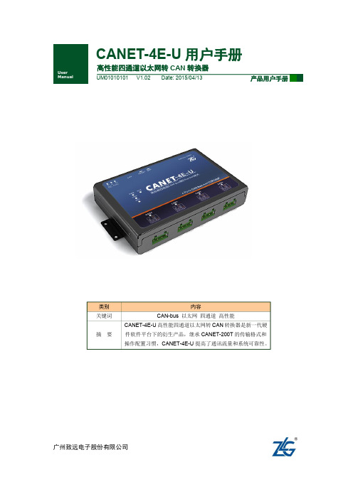
CANET_4E_U_使用说明
产品用户手册
©2013 Guangzhou ZHIYUAN Electronics Stock Co., Ltd. i
广州致远电子股份有限公司
CANET-4E-U 用户手册
高性能四通道以太网转 CAN 转换器用户手册
目 录
1. 功能简介................................................................................................................... 1
CANET-4E-U 用户手册
User Manual
高性能四通道以太网转 CAN 转换器
UM01010101 V1.02 Date: 2015/04/13
产品用户手册
类别 关键词 摘 要
内容 CAN-bus 以太网 四通道 高性能 CANET-4E-U 高性能四通道以太网转 CAN 转换器是新一代硬 件软件平台下的衍生产品,继承 CANET-200T 的传输格式和 操作配置习惯,CANET-4E-U 提高了通讯流量和系统可靠性。
3. 硬件连接使用说明................................................................................................... 9 4. 快速使用说明......................................................................................................... 10
4.1 4.2 4.3 设备 IP 出厂设置 ....................................................................................................... 10 用户获取设备 IP ........................................................................................................ 10 PC 机与设备网段检测 ............................................................................................... 11 4.3.1 Windows98/Me 网络设置 .................................................................................. 11 4.3.2 Windows2000/XP 网络设置 .............................................................................. 12 4.4 CANET-4E-U 与 USBCAN 接口卡通信 ................................................................... 15
USB2CAN模块用户手册说明书

USB2CAN MODULE User ManualUSB2CAN module is a‘plug and play’and bi-directional port powered USB to CAN converter which realizes long-distance communication between your Raspberry Pi/SBC/PC and other devices stably though CAN-Bus connection.With small size and convenient operation,It’s a cost-effective solution that are safe and reliable for all your data-conversion/device-protection applications for any experienced engineer interfacing to expensive industrial equipment yet simple enough for home use by an amateur hobbyist.USB2CAN can also be applied to obtain the data of car via the OBD connector,but you need to configured and secondary development by yourself.2.patible with Raspberry Pi Zero(W)/Pi3B+/PI4/Beaglebone/Tinker Board and any single board computer.2.Plug and Play USB device.No external power required.Support wider CAN baud rate,From 20Kbps to1Mbps can be programmed arbitrarily.3.On board STM32F0microcontroller,high speed data transfer with DMA technique.Support for CAN bus2.0A and2.0B specification.4.Power supply isolation,signal input/output isolation,Built-in surge and static protection.120 Ohm resistor selectable jumper feature.es with C/Python demos of Socket-CAN,detailed user manual and friendly technology support.4.1CAN connectorPinout4.2120Ohm Resistor Setting.A High-speed CAN bus (ISO 11898-2)must be terminated on both ends with 120Ohms.The USB2CAN module with a on-board 120Ωselectablejumer.Disable 120Ohm Resistor.Enable120Ohm Resistor.4.3LEDIndicate5.Run USB2CAN Test DemoUSB2CAN module can run properly without any additional driver request on all Linux system since version3.9.such as Ubuntu,Debian and Raspbian.If you meet problems in older system, You need to reconfigure the kernel drivers.Enable‘gs_usb.c’and install‘gs_usb.ko’into system. So notice that if you only compile this drivers,It may fail to load in system.At this time,compile fully with new configure.You can test the USB2CAN module any single board computer or PC with the right Linux version. We take Raspberry Pi4as an example to show you how to run the C/Python and can-utils demo.5.1Preparatory work5.1.1ConnectionThere are two way to test the USB2CAN module.One is plug two USB2CAN module into the USB Host of each Raspberry Pi.The other is plug two USB2CAN into one Raspberry Pi.But the codes and commands are a little bit different.And then connect the CAN_H pin and CAN_L pin to eachother.No GND pin connection requirement.Methods A Methods BUse two Raspberry Pi to test USB2CAN Use one Raspberry Pi to test USB2CAN 5.1.2ifconfig-aType command‘ifconfig-a’to check‘can0’device is available in system.If you plug two USB2CAN into one Raspberry PI,You will see one more‘can1’device.5.1.3demsgYou can type command‘demsg’for see more information about USB2CAN module at the bottom.5.2Use can-utils toolThis tool is a very easy way to test CAN commuincation by only type two command.5.2.1Install Toolssudo apt-get install can-utils5.2.2Initialize CAN portsudo ip link set can0type can bitrate125000sudo ifconfig can0up5.2.3Set one as receivercandump can05.2.4Set the other as sendercansend can0123#12345678905.2.5Test two module on one Raspberry PiDo as above steps,set‘can0’as receiver and‘can1’as sender.5.3Run C Demo(1)Load C Demo named‘usb2cantest’from our Wiki and up-zip it to the desktop of Rasbian./wiki/doku.php?id=usb_canOr /wiki/doku.php(2)Go to folder named‘c’and change the permissions.chmod-R a+x*(3)Set one as receiver,execute following commands in serial terminal.Now this Raspberry pi is blocked../can0_receive(4)Set the other Pi as sender,execute following commands../can0_send(5)You should see that the receiver has received the packet.(6)You also can plug two USB2CAN module on one Raspberry PI board to test.You should see two can socket“can0”and“can1”devices.So notice that you need to change“can0”to“can1”when you use“can1”device.5.4Run Python3DemoDownload Python Demo named‘python3’from our Wiki and up-zip it to Desktop(or wherever you want put it)./wiki/doku.php?id=usb_canOr /wiki/doku.phpThere are three files in the folder.‘send.py’and‘receive.py’is for you use two Raspberry Pi to test,and‘test.py’is for you use one Raspberry Pi and two USB2CAN module to test.(1)Check the Python version of your Raspbian.Python3.7.3default in2019-09-26-Raspbian.img. Our Demo can run on any Python3version.python3-V(2)If you can’t find the Python3in system.Install the Python3sudo apt-get install python3-pip(3)Install Python CAN library.sudo pip3install python-can(4)Set one Raspberry Pi as receiver.sudo python3receive.py(5)Set the other as sender.sudo python3receive.py(6)You will see the data received.(7)If you use one Raspberry Pi and two USB2CAN modeule for testing.Run‘test.py’and check the result.sudo python3test.py6.Now with previous demo’s code to show you how to program socket can in Raspbian with C and Python.The socket can is an implementation of CAN protocols(Controller Area Network)for Linux.CAN is a networking technology which has widespread use in automation,embedded devices,and automotive fields.While there have been other CAN implementations for Linux based on character devices,Socket CAN uses the Berkeley socket API,the Linux network stack and implements the CAN device drivers as network interfaces.The CAN socket API has been designed as similar as possible to the TCP/IP protocols to allow programmers,familiar with network programming,to easily learn how to use CAN sockets.For more Socket CAN detail please refer to below link:https:///doc/Documentation/networking/can.txt6.1Programming in C6.1.1For Sender’s codes(1):Create the socket,If an error occurs then the return result is-1.(2):Locate the interface to“can0”or other name you wish to use.The name will show when you execute“./ifconfig–a”.(3):Bind the socket to“can0”.(4):Disable sender’s filtering rules,this program only send message do not receive packets.(5):Assembly data to send.(6):Send message to the can bus.You can use the return value of write()to check whether all data has been sent successfully.(7):Close can0device and disable socket.6.2.3For Receiver’s codes(1)step1and(2)is same as Sender’s code.(3):It’s different from Sender’s.(4):Define receive filter rules,we can set more than one filters rule。
gzenpu-cantcp-02-以太网canbus数据转换器-用户手册说明书

广州恩浦电子有限公司Web: TEL*************以太网CANbus数据转换器CANTCP-02广州恩浦电子有限公司电话:************传真:************网址:邮箱:**************地址:广州市番禺区大石镇御峰国际5-6座942目录1. CANTCP-02功能简介 (3)1.1CAN总线概述 (3)1.2CANTCP-02简介 (3)1.3参数规格 (3)1.4系统特点 (4)1.5产品规范 (6)1.5.1LAN (6)2. 工作模式 (1)3. 售后服务 (2)1. CANTCP-02功能简介1.1 CAN总线概述CAN 是Controller Area Network的缩写(以下称为CAN),是ISO国际标准化的串行通信协议。
在当前的汽车产业中,出于对安全性、舒适性、方便性、低公害、低成本的要求,各种各样的电子控制系统被开发了出来。
由于这些系统之间通信所用的数据类型及可靠性的要求不尽相同,由多条总线构成的情况很多,线束的数量也随之增加。
为适应“减少线束的数量”、“通过多个LAN,进行大量数据的高速通信”的需要,1986 年德国电气商博世公司开发出面向汽车的CAN 通信协议。
此后,CAN 通过ISO11898 及ISO11519 进行了标准化,现在在欧洲已是汽车网络的标准协议。
现在,CAN 的高性能和可靠性已被认同,并被广泛地应用于工业自动化、船舶、医疗设备、工业设备等方面。
1.2 CANTCP-02简介CANTCP-02是广州恩浦电子有限公司开发的一款工业级以太网CAN-bus数据转换设备,符合CAN2.0A和2.0B规范,针对工业应用和煤矿等领域设计,满足工业自动化系统对设备严格的性能要求。
它内部集成了一路/两路CAN-bus接口和一路EtherNet接口以及TCP/IP协议栈,用户利用它可以轻松完成CAN-bus网络和EtherNet网络的互连互通,进一步拓展CAN-bus网络范围。
实验手册can-bus
CAN-BUS 实验手册(预印本)ELWE Lehrsysteme GmbH南京华维汽车新技术开发有限公司 译R e p r o d u c t i o n i s a l l o w e d o n l y f o r u s e w i t h E L W E -e q u i p m e n t .1 目 录3.720.00 CAN 总线的直接测量教师篇3.720.02 电控舒适系统的构成3.720.03 电控舒适系统的诊断3.720.04 两种舒适系统的比较3.720.06 电压信号信息篇R e p r o d u c t i o n i s a l l o w e d o n l y f o r u s e w i t h E L W E -e q u i p m e n t .1. CAN-BUS 整体系统安装结构图1.1 请如下图安装1.2 按下列设定步骤调试基本设定 步骤 备注 1 点火开关置“OFF ”0位置2 摇杆开关3(中央锁定开关)置SAFE 司机门与前乘客门3 切断电源例如:关闭电源开关 4 将司机门与前乘客门连接开关(2)置“门锁定”位置司机门:摇杆开关置右 前乘客门:摇杆开关置左 5 门锁(钥匙开关)置中间位 如:打开电源开关6 接通电源红灯闪烁表示处于锁定状态“SAFE ”R e p r o d u c t i o n i s a l l o w e d o n l y f o r u s e w i t h E L W E -e q u i p m e n t .1.3 CAN 总线中的直接测量进行直接测量时,必须启动司机门的“锁定与解锁”功能。
下表列出了必要的步骤:汽车解锁 步骤 备注1 左转门锁1中钥匙(逆时针) 司机门与前乘客门绿色指示灯亮 2用车钥匙激活门锁后,马上将摇杆开关3打到“解锁”位置,使其处解锁状态司机门和前乘客门3将门连接开关(2)置于“门解锁”状态,再回“门锁定”状态 司机进入车辆,防盗警报系统处于睡眠状态 4 打开点火开关电动窗可操作司机门锁定单元各功能元件位置图R e p r o d u c t i o n i s a l l o w e d o n l y f o r u s e w i t h E L W E -e q u i p m e n t .1. 中央控制单元1.1 目的与功能除了在舒适系统中的功能外,中央控制 单元还连接汽车网络的其它系统。
CANalyst-II+用户手册说明书
广州致远电子股份有限公司CANalyst-II+用户手册CAN-bus 总线分析仪类别内容关键词CANalyst-II+ 分析仪 摘要CANalyst-II+产品描述与使用指导修订历史版本日期原因V1.00 2015/06/26 创建文档目录1. 功能简介 (1)1.1产品概述 (1)1.2功能特点 (1)1.3典型应用 (2)2. 设备安装 (3)2.1供电模式 (3)2.1.1外部电源供电模式 (3)2.1.2USB总线供电模式 (3)2.2CAN-bus连接器 (3)2.3信号指示灯 (3)2.4系统连接 (4)2.4.1CAN总线连接 (4)2.4.2总线终端电阻 (5)2.4.3USB总线连接 (5)3. 软件安装及使用 (6)3.1系统要求 (6)3.2软件安装 (6)3.3初次使用指南 (6)4. 常见问题 (12)5. 检查和维护 (15)6. 附录:CAN2.0B协议帧格式 (16)7. 免责声明 (18)1. 功能简介1.1 产品概述CANalyst-II+高性能CAN接口卡是与USB2.0总线全速规范兼容的,集成1~2路CAN 接口的高性能型CAN-bus总线通讯接口卡。
采用CANalyst-II+高性能CAN接口卡,PC可以通过USB总线连接至CAN-bus网络,构成现场总线实验室、工业控制、高性能小区、汽车电子网络等CAN-bus网络领域中数据处理、数据采集的CAN-bus网络控制节点。
CANalyst-II+高性能CAN接口卡是CAN-bus产品开发、CAN-bus数据分析的强大工具;同时,具有体积小巧、即插即用等特点,也是便携式系统用户的最佳选择。
CANalyst-II+接口卡上自带电气隔离模块,使接口卡避免由于地环流的损坏,增强系统在恶劣环境中使用的可靠性。
CANalyst-II+高性能CAN接口卡支持Win2000/XP等操作系统,也支持Linux2.6版版本的操作系统。
汽车CANBUS总线数据解码盒使用手册
SCAN
SCAN电平电压
K
输出高电平电压
输出低电平电压
最小值 2.8 -0.3 3.4 -
典型值 -
最大值 5 0.7 0.4
单位 V V V V
最小值 3 0.5 3.65 9 -
典型值 3.6 1.4
-
最大值 4.25 1.75 4.55 1.5
单位 V V V V V
6.5 耗流(VBAT=12.7V)
汽车 CANBUS 总线数据解码盒 使用手册_V1.00
IVO core unit
文档名称: 版本: 日期: 状态: 文档控制号:
CC430 使用手册 1.00 2014-08-08 发布 CC430_使用手册_V1.00
CC430_使用手册_V1.00
1 / 11
IVO core unit
前言
在未声明之前,本公司有权根据技术发展的需要对本手册内容进行修改。
1. 绪论 2. CAN解码盒综述 2.1. CAN解码盒主要特性 2.2. 工作模式 2.3. CAN解码盒功能框图 3. CAN解码盒产品形态 3.1. 外观图 3.2. 连接件描述 3.3. 外观结构尺寸
CC430_使用手册_V1.00
CC430提供一个用于通讯的标准串口。包含数据信号线 TXD 和RXD,串口支 持的通讯波特率115200bps。串口配置为:8 位数据位,无奇偶校验,1 位停止 位,无数据流控。 4.4 总线接口
CAN总线分为高速和低速,高速CAN系统采用硬线是动力型,速度:500kbps, 控制ECU、ABS等;低速CAN是舒适型,速度:125Kbps,主要控制仪表、防盗等。
引脚
接触放电
空气放电
12V
CANCOM-100IE+智能转换器 RS232 485 422 转 CAN-bus 用户手册说明书

CANCOM-100IE+智能转换器RS232/485/422转CAN-bus修订历史目录1. 功能简介 (1)1.1概述 (1)1.2产品特性 (1)1.3典型应用 (1)2. 硬件描述 (2)2.1产品外观 (2)2.2接口描述 (2)2.2.1RS-232接口引脚定义 (2)2.2.2接口定义 (3)2.3指示灯说明 (3)2.4CAN总线连接 (4)3. 配置说明 (5)3.1配置方式进入 (5)3.2软件说明 (5)3.2.1转换参数 (6)3.2.2串口参数 (7)3.2.3CAN参数 (7)3.2.4举例介绍验收滤波的设置 (8)3.2.5按键说明 (9)4. 转换示例 (10)4.1透明转换 (10)4.1.1帧格式 (11)4.1.2转换方式 (11)4.1.3转换示例 (12)4.2透明带标识转换 (13)4.2.1帧格式 (13)4.2.2转换方式 (14)4.2.3转换示例 (15)4.3格式转换 (16)4.4Modbus转换 (18)4.4.1帧格式 (18)4.4.2转换方式 (19)4.4.3转换示例 (20)5. 设备固件升级 (22)6. 设备测试 (24)6.1设备准备 (24)6.2通讯测试 (24)7. 安装尺寸 (25)8. 免责声明 (26)1. 功能简介1.1 概述CANCOM-100IE+ 智能协议转换器可以快速将RS-232/485/422通讯设备连接CAN-bus 现场总线。
转换器支持600~230400bps速率,5Kbps~1Mbps的CAN-bus通讯速率。
转换器提供四种数据转换模式:透明转换、透明带标识转换,格式转换,Modbus转换(Modbus转换功能仅在CAN总线设备报文可编辑的情况下可以使用)。
CANCOM-100IE+转换器提供配置软件,可以灵活设置CANCOM-100IE+的运行参数。
1.2 产品特性●实现CAN-bus与RS-232/485/422的双向数据通讯;●支持CAN2.0A 和CAN2.0B 协议,符合ISO/DIS 11898规范;●集成1路CAN-bus通讯接口,支持用户自定义的通讯波特率;●CANCOM-100IE+集成1路3线式RS-232通讯接口,集成1路2线式RS-485通讯接口,集成1路4线式RS-422通讯接口,通讯速率在600~230400bps之间可设定;●提供四种数据转换模式:透明转换、透明带标识转换,格式转换,Modbus转换;●支持CAN-bus虚拟PC串口应用;●CAN-bus电路采用DC 2500V电气隔离;●可以用在有安全防爆需求的环境中(*);●工作温度:-40℃~+85℃,工作功率:低于2W。
综合实验十二 CAN-Bus接口控制实验

实验三十四CAN-bus接口控制实验一.实验目的通过调用CAN程序库SJA1000_PELI.LIB的基本函数,实现实验板上CAN节点的初始化以及CAN 节点的自发自收测试。
二.实验设备及器件IBM PC 机一台单片机仿真器、编程器、实验仪三合一开发平台一台三.实验内容编写一段程序,调用SJA1000_PELI.LIB中的函数,实现CAN节点的初始化,能够进行数据的自发自收,并能在LED上显示相关的信息。
四.实验要求学会对CAN节点的基本操作,理解实现CAN通信的基本流程。
五.实验步骤1.将CAN-bus PARK的CSCAN与P2.7相连接。
2.将CAN-bus PARK的RSTCAN与P1.0脚相连接。
3.如果用户采用中断方式,将4.利用SJA1000_PELI库编写CAN节点的初始化和自发自收程序。
5.利用ZLG7290,将CAN节点自发自收数据的成功与否显示出来。
六.实验预习要求1.阅读关于CAN和CAN相关器件的基本介绍,具备CAN和CAN相关器件的基本知识。
2.阅读《SJA1000_PELI库说明及其使用》,了解在如何在程序中应用SJA1000_PELI库。
七.实验参考程序#include <REG52.H>#include "VIIC_C51.h" //I2C程序库头文件#include "Sja1000_peli.h" //CAN程序库头文件#define uchar unsigned char#define ZLG7290 0x70sbit RESET_PIN=P1^0;uchar Display_Buffer[5]={0x0d,0x15,0x15,0x10}; //显示GOODuchar CAN_Baudrate_Filter_Buffer[9]={14,0,0,0,0,0xff,0xff,0xff,0xff};//存放设置波特率和滤波器的数据uchar Send_CAN_Info_ID[5]={0x88,0x00,0x00,0x00,0x00};//存放信息帧的数据,符合CAN2.0Buchar Send_Data_For_Self[8]={0x01,0x02,0x03,0x04,0x05,0x06,0x07,0x08};//存放数据帧的数据uchar ScanNum[1];/*--------------------------------------------------------------------------------------------------- ** 函数原型: void Delay_ms(uchar j)** 功能描述: 该函数用于不精确的延时。
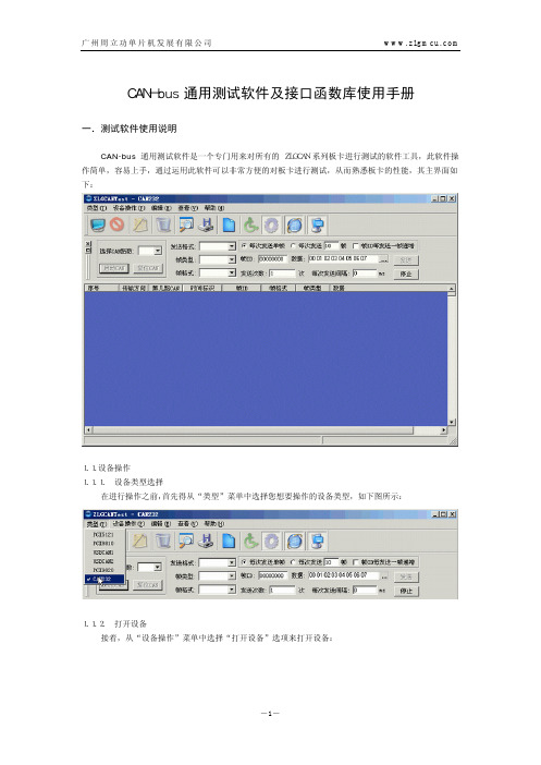
CAN-bus 通用测试软件及接口函数库使用手册
}VCI_CAN_STATUS,*PVCI_CAN_STATUS;
参数:
ErrInterrupt 中断记录,读操作会清除;
regMode CAN 控制器模式寄存器;
regStatus CAN 控制器状态寄存器;
regALCapture CAN 控制器仲裁丢失寄存器;
regECCapture CAN 控制器错误寄存器;
当您打开设备成功后,您可以从“设备操作”菜单中选择“参数设置”选项来进行一些参数设置(如 果您想采用默认设置的话,可以略过此步骤):
(1)如果您操作的设备是 CAN232 的话,将会弹出以下对话框:
-2-
广州周立功单片机发展有限公司
在此对话框中可以读取和更改 CAN 控制器的一些参数设置。在设置滤波器时,需要输入的参数长度为 12 个字节,输入格式类似于“FF FF FF FF FF FF FF FF FF FF FF FF ”(为 16 进制),具体参数怎么设 置请参阅后面的接口函数库说明中的 VCI_SetReference 函数中的参数说明。 (2)而如果您操作的是其它设备的话,则会弹出以下对话框:
ERR_BUFFERCREATE
0x00008000
内存不足
2.3.函数库中的数据结构定义
2.3.1. 存储 ZLGCAN 系列接口卡信息的数据结构
定义:
typedef struct _VCI_BOARD_INFO{
USHORT hw_Version;
USHORT fw_Version;
regEWLimit CAN 控制器错误警告限制寄存器;
regRECounter CAN 控制器接收错误寄存器;
CAN-bus 通用测试软件及接口函数库使用手册(LINUX)

系统保留。
4.3.3 存储 CAN 控制器状态的数据结构 定义: typedef struct _VCI_CAN_STATUS{
UCHAR ErrInterrupt; UCHAR regMode; UCHAR regStatus;
-3-
广州周立功单片机发展有限公司
w w w. z l g m c u . c o m
USHORT hw_Version;
USHORT fw_Version;
USHORT dr_Version;
USHORT in_Version;
USHORT irq_Num;
BYTE
can_Num;
CHAR
str_Serial_Num[20];
CHAR
str_hw_Type[40];
USHORT Reserved[4];
CAN 控制器错误报警 CAN 控制器消极错误 CAN 控制器仲裁丢失 CAN 控制器总线错误
设备已经打开 打开设备错误 设备没有打开
缓冲区溢出 此设备不存在 装载动态库失败 执行命令失败错误码
内存不足
4.3 函数库中的数据结构定义
4.3.1 存储 ZLGCAN 系列接口卡信息的数据结构
定义:
typedef struct _VCI_BOARD_INFO{
SendType
发送帧类型,=0时为正常发送,=1时为单次发送,=2时为自发自收,=3时为单次自
发自收,只在此帧为发送帧时有意义。
RemoteFlag 是否是远程帧;
ExternFlag 是否是扩展帧;
ID
报文 ID;
DataLen
数据长度(<=8),即 Data 的长度;
Data
JetBox 8152 Linux CANBus 用户手册说明书

JetBox 8152 Linux CANBusUser ManualS to ck C he ck .c omCopyright NoticeCopyright© 2012 Korenix Technol ogy Co., Ltd. All rights reserved.Reproduction without permission is prohibited.Information provid ed in this manual is intend ed to be accurate and reliabl e.However, the original manufacturer assumes no responsibility for its use, or for any infringements upon the rights of third parties that may result from its use.The material in this d ocument is for product information only and is subject to change without notice. Whil e reasonabl e efforts have been mad e in thepreparation of this d ocument to assure its accuracy, Korenix assumes no liabilitiesresulting from errors or omissions in this d ocument, or from the use of the information contained herein.Korenix reserves the right to make changes in the product d esign without noticeto its users.AcknowledgmentsKorenix is a registered trad emark of Korenix Technol ogy Co., Ltd.All other trad emarks or registered marks in the manual bel ong to their respective manufacturers.S to ck C he ck .c omTable of ContentCopyright Notice (2)Acknowledgments (2)Table of Content.............................................................................................................3 Chapter 1 Introduction...............................................................................................4 Chapter 2 Hardware Configuration.. (6)2-1 Pin Assignment...........................................................................................6 2-2 Jumper Setting: JP6....................................................................................6 Chapter 3Software Configuration..............................................................................7 3-1 Installation..................................................................................................7 3-2Example (8)Chapter 4 Korenix Library Reference (9)4-1 How to Use Library.....................................................................................9 4-2 Functions. (9)4-3 Structure..................................................................................................15 Chapter 5 Appendix.. (17)5-1 Baud Rate Table........................................................................................17 5-2 Error Code Table.......................................................................................18 5-3 Notes........................................................................................................19 5-4 Revision history........................................................................................20 5-5 Customer Service. (20)S to ck C he ck .c omChapter 1 IntroductionThe JetBox 8152 has two ports for I/O communications, One RS-232/422/485 port and one CANBUS port. The CAN (Controller Area Network) is a serial bus system especially suited for networking "intelligent" I/O devices as well as sensors andactuators within a machine or plant. Characterized by its multi-master protocol,real-time capability, error correction, high noise immunity, and the existence of many different silicon components, the CAN serial bus system, originally developed byBosch for use in automobiles, is increasingly being used in industrial automation.CANbusThis section describes how to program and use the CANBUS. It provides a description of the I/O memory map of the chip and discussion of the internal registers to aid youin programming your CAN controller chip.Defined Memory Mapping and InterruptThe CANBUS occupies 2 bytes of memory space. You can set the base address andaccess to the internal resources of the SJA1000 CAN controller chip. The SJA1000 chip access is multiplexed in such a way that the host must first write to 300h the internal address of the CAN chip and after that perform a write to address 301h with the actual data to be written into the desired memory location. Address 302h is a hardware-reset function of the SJA1000. Performing a read or write to this addressS to ck C he ck .c omwill cause a hardware reset to the CAN controller. You may need to reset the chip in case of an unrecoverable error in the CAN controller chip. And your can use interrupt the main processor when a message is received or transmitted if interrupts areenabled on the JetBox 8152. By using interrupts you can write powerful code to CAN.Example ProgrammingWrite 300H to the CAN controller Control byte located in the on-chip address 0. The Example is listed below:Outportb (0x300, 0x00) : Write CAN Address 0 (Control Register ) Outportb (0x301, 0x78) : Write Data of CAN Address 0 (Control Register )And please see “SJA1000.pdf” for further information of the SJA1000 chip.Description Factory SettingBase Address 300HData Of Address301H Hardware Reset Of SJA1000 Chips302H Interrupt Require Quest11S to ck C he ck .c omChapter 2 Hardware Configuration2-1 Pin AssignmentThe CANBUS is use DB9 standard connector. The following tables show the CANBUS signal connections of this connector.Note 1: The CANBUS DB9-pin out conforms to the ISO 11898/2 standard2-2 Jumper Setting: JP6JP6: CANBUS Terminal Resistor SelectionNote 2: The JP6 is the CANbus termination jumper. Only two terminationjumpers should be closed at the endpoints of the CANbus. Value Terminator Resistor (120 Ω). The minimum speed is 20k bps. The maximum speed is 1M bps. But when CANBUS terminator is disabled , the maximize speed of CANBUS is 125k bps . If you want to use high speed (1M bps), please enable terminator.DB-9 CANBUS CANBUS Signal CANBUSDescription1 N.C - 6 N.C -2 CAN-L Dominant Low 7 CAN-H Dominant High3 CAN-GroundIsolated Ground8 N.C - 4 N.C - 9 N.C -5 Ground Digital GroundCase Case GroundFactory presetS to ck C he ck .c omChapter 3 Software Configuration3-1 InstallationPrerequisitesTo make CANBus work correctly. We have to install three components first. Make sure your network is connected.1. GCC : call “yum install gcc ”2. OpenSSL : call “yum install openssl ”3. OpenSSL-devel : call “yum install openssl-devel.i386”After install these components, the CANBUS library and follow example code will work successfully.Do the following steps to setup the driver1. Login in as root. ( username : root, password : korenix )2. Default CanBus code are built-in jetbox linux environment. Go to the path/CanBus and you will see the follow directory.3. In the “library” directory. You will see the two files below.libmycanbus.so.1.0.0 :It contains all CanBus functions that user can use it to program. mycanbus.h :It defines CanBus structure, message type and baud rates settings.All details will be shown in Chapter 4.4. In the “example” directory. You will see the files below.S to ck C he ck .c omCall “make ” to compile files and “make install ” to install library to /usr/lib.All details will be shown in next session.3-2 Exampl eCANBus example for Linux is a simple CAN monitor for viewing and transmitting CANmessages. When you call “make” and “make install” to compile/install all need files. It will generate two sample files, “cantest ” and “canrcv ”.cantestThere will be four command as below :cantest -i : Initial CanBus Chip and set baud rate to 125K.cantest -r : Reset CanBus Chip cantest -s : Get CanBus statuscantest -w : Write CAN message. We use standard message type in this example. canrcvThis example show you how to receive CAN message from other CANBus. Before to receive CAN messages, you have to reset CAN chip first and initial it.S to ck C he ck .c omChapter 4 Korenix Library ReferenceThis section shows how to use Korenix CANbus Library to develop your program. When you call “make install” in the example directory, the library will be installed to the /usr/lib path.4-1 How to Use LibraryWe use dlopen to load CANBus library. You will see it in the example. Like thishandle = dlopen ("/usr/lib/libmycanbus.so.1", RTLD_NOW);Usedlsym to take a "handle" of a dynamic library returned by dlopen and the null terminated symbol name, returning the address where that symbol is loaded.Init_CanBus = dlsym(handle, "Init_Can");Call “man dlopen” to detail information of dlopen, dlsym.All functions (symbol) are listed in next session.4-2 FunctionsThe CanPort library provides the following functionsInit_Canvoid Init_Can(BYTE BTR0, BYTE BTR1)ParametersBTR0BUS TIMING REGISTER 0 BTR1BUS TIMING REGISTER 1This function sets configuration parameters to initialize the CAN controller.Configuration parameters include baud rate. Valid Baud rate codes can be taken from the Baud Rate Table .S to ck C he ck .c omThis function will also set up the Interrupt Enable Register, Acceptance Code Register, Acceptance Mask Register and Output Control Register.Can_Chip_Resetvoid Can_Chip_Reset(void)This function resets the CAN controller to default state.The transmitting and receiving of messages will be canceled, and messages in the driver buffer will be cleared as well.Can_Send_Messagevoid Can_Send_Message(CANMsg *MsgToSend)Parameters MsgToSendMessage to transmit. Please refer to Structure for details.Can_Receive_Messagevoid Can_Receive_Message(CANMsg *MsgToRead)Parameters MsgToReadReturns a CAN message from the receive queue.Can_Status_ReportBYTE Can_Status_Report(void) ReturnStatus of CAN controllerGet the current status of the CAN controller.S to ck C he ck .c omNote 3: More information of Status is given in the data sheet of SJA 1000 in section 6.4.5 Status Register (SR).Can_Set_Filtervoid Can_Set_Filter(DWORD dwACR, DWORD dwAMR)This function sets the Acceptance Code and Acceptance Mask of the CAN controller. The CAN controller must set to reset mode when calling the function.Note 4: More information of Status is given in the data sheet of SJA 1000 insection 6.4.15 Acceptance Filter.Parameters dwACRAcceptance Code RegisterdwAMRAcceptance Mask RegisterExampleThe following example shows the parameter values for dwACR and dwAMR in order to accept only the Data messages of standard frame in the range 110h to 113h. dwACR:001 0001 0000dwAMR:000 0000 0011 Valid IDs: 001 0001 00xx ID 110h: 001 0001 0000 ID 111h: 001 0001 0001 ID 112h: 001 0001 0010 ID 113h:001 0001 0011So the value of dwACR is 0x221FFFFF and the value of dwAMR is 0x007FFFFF.S to ck C he ck .c omCan_Reset_Filtervoid Can_Reset_Filter(void)This function reset the Acceptance Code and Acceptance Mask Register of the CAN to default value (It means accept all CAN message).Can_Interrupt_StatusBYTE Can_Interrupt_Status(void)ReturnThe value of Interrupt RegisterNote 5: More information of Status is given in the data sheet of SJA 1000 insection 6.4.6 Interrupt Register (IR).Can_Mode_Setvoid Can_Mode_Set(BYTE bMode)Parameters bMode operation modeDescriptionValue SLEEP_MODE0x10 ACCEPT_FILTER_MODE 0x08 SELF_TEST_MODE 0x04 LISTEN_ONLY_MODE 0x02 RESET_MODE 0x01 NORMAL_MODE 0x00S to ck C he ck .c omNote 6: More information of Status is given in the data sheet of SJA 1000 in section 6.4.3 Mod Register (MOD).Can_Set_BTRvoid Can_Set_BTR(BYTE BTR0, BYTE BTR1)Parameters BTR0BUS TIMING REGISTER 0BTR1BUS TIMING REGISTER 1This function only sets the baud rate to CAN controller.Can_Set_Commandvoid Can_Set_Command(BYTE bCmd)Parameters bCmdCommand modeDescriptionValue CLEAR_DATA_OVERRUN0x08 RELEASE_RECEIVE_BUFFER 0x04 ABORT_TRANSMISSION 0x02 TRANSMISSION_REQUEST0x01Note 7: More information of Status is given in the data sheet of SJA 1000 insection 6.4.4 Command Register (CMR).S to c k C he ck .c omCan_Get_ECRBYTE Can_Get_ECR(void)ReturnThe value of Error Code Capture Register.Note 8: Please refer to Error Code Table for details.Note 9: More information of Status is given in the data sheet of SJA 1000 insection 6.4.9.Can_Get_ALCBYTE Can_Get_ALC(void)ReturnThe value of Arbitration Lost Capture Register.Can_Get_EWLBYTE Can_Get_EWL(void)ReturnThe value of Error Warning Limit Register.The error warning limit can be defined within this register. The default value (after hardware reset) is 96.Note 10: More information of Status is given in the data sheet of SJA 1000 insection 6.4.10.S to ck C he ck .c omCan_Get_TXERROR_COUNTERBYTE Can_Get_TXERROR_COUNTER(void)ReturnThe value of transmit error.The TX error counter register reflects the current value of the transmit error counter.Note 11: More information of Status is given in the data sheet of SJA 1000 in section 6.4.12.Can_Get_RXERROR_COUNTERBYTE Can_Get_RXERROR_COUNTER(void)ReturnThe value of receive error.The RX error counter register reflects the current value of the receive error counter.Note 12: More information of Status is given in the data sheet of SJA 1000 in section 6.4.11.4-3 StructureThe CanPort API defines the following structures CANMsg :Defines a CAN messagetypedef struct {DWORD ID; BYTE MSGTYPE; BYTE LEN; BYTE DATA[8]; } CANMsg;S to ck C he ck .c omKorenix | Korenix Library Reference 16ID11/29-bit CAN identifier.MSGTYPEBit mask indicating the type of the message. Several message types can be combined. IdentiferValue DescriptionMSGTYPE_STANDARD00hData Frame. CAN message with data contents and an 11-bit CAN ID.MSGTYPE_RTR 01h Remote Transmit Request (RTR).MSGTYPE_EXTENDED02hData Frame. CAN message with data contents according to CAN 2.0B standard (29-bit CAN ID).LENNumber of data bytes in a data message (Data Length Code).DATA Data bytes of a CAN message. The size can be 0 to 8 bytes.S to ck C he ck .c omKorenix | Appendix 17Chapter 5 Appendix5-1 Baud Rate Tabl eBaud Rate (bps) Predefined BTR0 BTR1 BTR0 BTR15K BAUD_5K 7F 7F 10K BAUD_10K 67 2F20K BAUD _20K 53 2F 50K BAUD _50K 472F 100K BAUD _100K 432F 125K BAUD _125K 03 1C 250K BAUD _250K 01 1C 500K BAUD_500K 00 1C 1000KBAUD_1M0014The following Baud Rates are also common: Baud Rate (bps) BTR0 BTR1 33.33K 1D14 47.6K14 14 83.33K 4B 14 95.23K C3 4E 800K 0016Note 13: More information on setting the bit rate is given in the data sheet of SJA 1000 in section 6.5.S to ck C he ck .c om5-2 Error Code Tabl eBIT 7 BIT 6 BIT 5 BIT 4 BIT 3 BIT 2 BIT 1 BIT 0 Description 0 0 bit error 0 1 form error 1 0 stuff error1 1 other type of error0 error occurred during reception 1 error occurred during transmission0 0 0 1 1 start of frame0 0 0 1 0 ID.28 to ID.21 0 0 1 1 0 ID.20 to ID.18 0 0 1 0 0 bit SRTR 0 0 1 0 1 bit IDE 0 0 1 1 1 ID.17 to ID.13 0 1 1 1 1 ID.12 to ID.5 0 1 1 1 0 ID.4 to ID.0 0 1 1 0 0 bit RTR 0 1 1 0 1 reserved bit 1 0 1 0 0 1 reserved bit0 0 1 0 1 1 data length code 0 1 0 1 0 data field 0 1 0 0 0 CRC sequence 1 1 0 0 0 CRC delimiter 1 1 0 0 1 acknowledge slot 1 1 0 1 1 acknowledge delimiter111end of frameS to c k C he ck .c om1 0 0 1 0 intermission 1 0 0 0 1 active error flag 1 0 1 1 0 passive error flag 1 0 0 1 1 tolerate dominant bits 1 0 1 1 1 error delimiter111overload flag5-3 NotesNote 1: The CANBUS DB9-pin out conforms to the ISO 11898/2 standard..6Note 2: The JP6 is the CANbus termination jumper. Only two terminationjumpers should be closed at the endpoints of the CANbus. Value Terminator Resistor (120 Ω). The minimum speed is 20k bps. Themaximum speed is 1M bps. But when CANBUS terminator is disabled , the maximize speed of CANBUS is 125k bps . If you want to use highspeed (1M bps), please enable terminator...........................................6 Note 3: More information of Status is given in the data sheet of SJA 1000 insection 6.4.5 Status Register (SR).........................................................11 Note 4: More information of Status is given in the data sheet of SJA 1000 insection 6.4.15 Acceptance Filter..........................................................11 Note 5: More information of Status is given in the data sheet of SJA 1000 insection 6.4.6 Interrupt Register (IR).....................................................12 Note 6: More information of Status is given in the data sheet of SJA 1000 insection 6.4.3 Mod Register (MOD)......................................................13 Note 7: More information of Status is given in the data sheet of SJA 1000 in section 6.4.4 Command Register (CMR)..............................................13 Note 8: Please refer to Error Code Table for details....................................14 Note 9: More information of Status is given in the data sheet of SJA 1000 in section 6.4.9.........................................................................................14 Note 10: More information of Status is given in the data sheet of SJA 1000in section 6.4.10...................................................................................14 Note 11: More information of Status is given in the data sheet of SJA 1000in section 6.4.12 (15)S to ck C he ck .c omNote 12: More information of Status is given in the data sheet of SJA 1000in section 6.4.11...................................................................................15 Note 13: More information on setting the bit rate is given in the data sheetof SJA 1000 in section 6.5 (17)Note: You can get the SJA1000 datasheet from following website: /documents/data_sheet/SJA1000.pdf5-4 Revision historyV0.1by 2012/9/4- Change default CANbus terminator jump setting (JP6) to enable5-5 Customer ServiceKorenix Technologies Co., Ltd.Business service: *****************Customer service: ********************S to ck C he ck .c om。
汽车CAN总线详细教程

2003年,大众集团在新PQ35平台上使用五重结构的Canbus系统,并且出现了单线的LIN-BUS。
CAN技术的发展
20世纪80年代,Bosch的工程人员开始研究用于汽车的串行总线系统,因为当时还没有一个网络协议能完全满足汽车工程的要求。参加研究的还有Mercedes-Benz公司、Intel公司,还有德国两所大学的教授。 1986年, Bosch在SAE(汽车工程人员协会)大会上提出了CAN 1987年,INTEL就推出了第一片CAN控制芯片—82526;随后Philips半导体推出了82C200。 1993年,CAN的国际标准ISO11898公布 从此CAN 协议被广泛的用于各类自动化控制领域。
但是轿车上基于CAN的控制网络至今仍是各大公司自成系统,没有一个统一标准。
基于CAN的应用层协议应用较通用的有两种:DeviceNet(适合于工厂底层自动化) 和 CANopen(适合于机械控制的嵌入式应用)。 任何组织或个人都可以从DeviceNet供货商协会(ODVA)获得DeviceNet规范。购买者将得到无限制的、真正免费的开发DeviceNet产品的授权。 DeviceNet自2002年被确立为中国国家标准以来,已在冶金、电力、水处理、乳品饮料、烟草、水泥、石化、矿山等各个行业得到成功应用,其低成本和高可靠性已经得到广泛认同。
总线技术及应用
PART 1
CAN 数据总线(CAN BUS)
点击此处添加副标题
演讲人姓名
202X
CAN通信技术概述
CAN ( Controller Area Network ) 即控制器局域网络。由于其高性能、高可靠性、及独特的设计,CAN越来越受到人们的重视。国外已有许多大公司的产品采用了这一技术。
CAN-bus 通用测试软件及接口函数库使用手册V2.91(1)
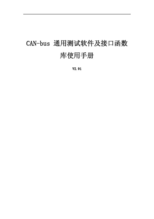
CAN-bus通用测试软件及接口函数库使用手册V2.91目录1.测试软件使用说明 (1)1.1.设备操作 (1)1.1.1.设备类型选择 (1)1.1.2.滤波设置 (2)1.1.3.启动CAN (2)1.1.4.获取设备信息 (3)1.1.5.发送数据 (3)1.2.辅助操作 (3)1.2.1.帧ID显示方式 (3)1.2.2.帧ID显示格式 (4)1.2.3.继续显示发送和接收的数据 (4)1.2.4.暂停显示发送和接收的数据 (4)1.2.5.滚动 (4)1.2.6.显示帧数 (4)nguage (4)2.接口函数库说明及其使用 (5)2.1.接口卡设备类型定义 (5)2.2.错误码定义 (5)2.3.函数库中的数据结构定义 (6)2.3.1.VCI_BOARD_INFO (6)2.3.2.VCI_CAN_OBJ (6)2.3.3.VCI_CAN_STATUS (7)2.3.4.VCI_ERR_INFO (8)2.3.5.VCI_INIT_CONFIG (8)2.3.6.CHGDESIPANDPORT (10)2.3.7.VCI_FILTER_RECORD (10)2.4.接口库函数说明 (10)2.4.1.VCI_OpenDevice (10)2.4.2.VCI_CloseDevice (12)2.4.3.VCI_InitCan (13)2.4.4.VCI_ReadBoardInfo (18)2.4.5.VCI_ReadErrInfo (19)2.4.6.VCI_ReadCanStatus (23)2.4.7.VCI_GetReference (24)2.4.8.VCI_SetReference (28)2.4.9.VCI_GetReceiveNum (33)2.4.10.VCI_ClearBuffer (34)2.4.11.VCI_StartCAN (35)2.4.12.VCI_ResetCAN (37)2.4.13.VCI_Transmit (38)2.4.14.VCI_Receive (39)2.5.接口库函数使用方法 (40)2.5.1.VC调用动态库的方法 (40)2.5.2.VB调用动态库的方法 (40)2.6.接口库函数使用流程 (41)3.Linux下动态库的使用 (42)3.1.驱动程序的安装 (42)BCAN驱动的安装 (42)3.1.2.PCI5121驱动的安装 (42)3.2.动态库的安装 (42)3.3.动态库的调用及编译 (42)1.测试软件使用说明CAN-bus通用测试软件是一个专门用来对所有的ZLGCAN系列板卡进行测试的软件工具,此软件操作简单,容易上手,通过运用此软件可以非常方便的对板卡进行测试,从而熟悉板卡的性能,其主界面如下:1.1.设备操作1.1.1.设备类型选择在进行操作之前,首先得从“类型”菜单中选择您想要操作的设备类型,如下图所示:此时会弹出“选择设备”对话框:在这个对话框中您可以选择您要打开的设备索引号和CAN通道,以及设置CAN的初始化参数,然后点“确定”按钮来打开设备操作窗口(或者也可以点击“确定并启动CAN”按钮打开设备操作窗口并自动打开设备和启动CAN通道)。
CAN-bus产品技术配置手册
CAN-bus产品技术配置手册(Ver2.2)2、文档结构 (4)二、CAN-MixNet设备产品目录 (5)1、多效用CAN-bus网关产品 (5)2、多路CAN-bus以太网网关关产品 (5)3、CAN转RS232或RS485透明数据传输产品 (5)4、CAN以太网交换机 (5)三、进入设备的管理效用 (6)1、使用管理端口进行参数设置 (6)2、使用Telnet进行参数设置 (8)3、默认的管理口令 (9)四、配置主菜单效用说明及通用配置项 (10)1、ICAN主菜单 (10)2、SNode主菜单 (11)3、TNode、ENode主菜单 (12)4、通用配置菜单项 (13)5、配置菜单操作默认规则 (14)五、通用菜单项配置 (15)1、配置CAN端口n参数 (15)2、配置RS232/RS485端口参数 (25)3、选择工作模式 (32)4、查看内存情况 (34)5、查看IP、网络物理地址. (34)6、全局网络配置 (35)7、IP认证管理. (38)8、口令设置 (41)9、恢复默认设置. (41)10、检查TCP/IP连接. (41)11、重新启动. (42)12、技术支持及最新产品. (42)13、退出 (42)六、SNode设备专用配置项 (43)1、配置转发规则n (43)七、CAN网络的网段划分 (45)1、CAN网络网段划分及作用 (45)2、CAN硬件过滤器工作原理(SJA1000) (46)3、CAN网段划分示例 (51)4、使用软CAN ID过滤器 (52)八、自定义速率计算 (53)1、自定义速率实现原理 (53)2、CAN-MixNet设备对自定义速率支持的方式 (53)3、设置自定义速率的过程 (54)九、CAN交换机工作方式 (56)1、CAN交换机工作原理 (56)2、CAN交换机应用拓扑图 (57)2、通讯数据结构 (59)3、发送CAN报文详解 (60)4、接收CAN报文详解 (61)5、CAN ID详解 (62)十一、CAN总线参数 (63)1、CAN端口标准参数 (63)2、CAN传输电缆 (63)3、CAN端口防护 (64)十二、RS485总线参数 (65)1、RS485端口参数 (65)2、RS485端口防护 (65)十三、电源系统 (66)1、ICAN电源系统 (66)2、SNode电源系统 (66)3、TNode-N、TNode电源系统 (66)4、ENode (66)十四、文档声明 (67)一、手册使用说明1、适用范围及更新此手册适用于所有的CAN-MixNet产品,包括:ICAN、TNode-N、TNode、SNode、和ENode。
基于Qt的多接口设备模拟软件设计与实现

基于Qt的多接口设备模拟软件设计与实现摘要:针对具备多路CAN口、多路串口,具有高并发、高响应等特征,但存在价格昂贵且体积较大等缺点的系统,基于Qt的用户界面开发框架,提出了通过软件模拟系统相关接口和功能的方法。
该软件在模拟系统接口数据的同时,实现对各种不同类型数据的灵活设置,可模拟系统的各种输出数据。
经过测试,模拟软件运行稳定,响应及时,能够完成对系统基本接口及功能的模拟,方便开发人员进行数据通信,轻松完成场景搭建。
关键词:CAN口、串口、模拟软件1引言在某型设备进行通信测试过程中,需要通过具备多个CAN口、多个串口的系统与其进行数据交互。
该设备对实时性要求高,需要系统具备毫秒级响应能力;同时,该设备同时进行多个CAN口、多个串口的数据通信,要求系统具备并行处理能力。
目前在用的系统,存在价格昂贵、体积较大等缺点,从经济方面考虑,其性价比较低,从易用方面考虑,其体格笨重不便使用。
针对如此现实情况,结合设备测试的需求及系统的特点,采用软件模拟系统的相关功能,搭配CAN接口盒和串口扩展设备,实现对某型设备的通信测试,从而达到经济、易用的目的。
Qt是基于C++语言的图形用户界面开发框架,具有跨平台特性,且拥有面向对象开发、丰富的API及易用且开源的开发环境等特点。
同时,Qt提供了丰富的类,采用QSerialPort和QSerialPortInfo类,可方便地完成对串口的操作;采用Qthread类进行多任务处理,从而实现多个功能模块的同时运行。
USBCAN-II是高性能的工业级CAN接口卡,兼容USB2.0全速规范,带有2路CAN接口。
采用该接口卡,PC机可通过USB总线,方便地连接至CAN网络,构成CAN网络领域的数据采集及数据处理。
2模拟软件设计2.1模拟软件体系模拟软件主要包括设备管理和功能模拟两个部分。
设备管理主要完成对接口设备的设置、接口数据的拆包和组包以及接口数据的保存;功能模拟主要完成不同功能模块的设置、不同数据的设置及接口数据的解析和处理。
- 1、下载文档前请自行甄别文档内容的完整性,平台不提供额外的编辑、内容补充、找答案等附加服务。
- 2、"仅部分预览"的文档,不可在线预览部分如存在完整性等问题,可反馈申请退款(可完整预览的文档不适用该条件!)。
- 3、如文档侵犯您的权益,请联系客服反馈,我们会尽快为您处理(人工客服工作时间:9:00-18:30)。
ERR_DEVICENOTEXIST
0x00001000 此设备不存在
ERR_LOADKERNELDLL
0x00002000 装载动态库失败
ERR_CMDFAILED
0x00004000 执行命令失败错误码
ERR_BUFFERCREATE
0x00008000 内存不足
ERR_CANETE_PORTOPENED 0x00010000 端口已经被打开
ERR_CANETE_INDEXUSED 0x00020000 设备索引号已经被占用
3
1.3 函数库中的数述:
VCI_BOARD_INFO 结构体包含 CAN 系列接口卡的设备信息。结构体将在 VCI_ReadBoardInfo 函数中被填充。 typedef struct _VCI_BOARD_INFO {
2. LINUX 下动态库的使用 .......................................................................................... 37 2.1. 驱动程序的安装 ..................................................................................................... 37 2.1.1. USBCAN 驱动的安装 .......................................................................................37 2.2. 动态库的安装 ......................................................................................................... 37 2.3. 动态库的调用及编译 ............................................................................................. 37
2011
CAN-bus 接口函数库 使用手册 V1.0
--北京爱泰电子出品
1
目录
1. 接口函数库说明及其使用 ........................................................................................ 3 1.1 接口卡设备类型定义 ............................................................................................... 3 1.2 错误码定义 ............................................................................................................... 3 1.3 函数库中的数据结构定义.......................................................................................4 1.3.1. VCI_BOARD_INFO...............................................................................................4 1.3.2. VCI_CAN_OBJ .....................................................................................................5 1.3.3. VCI_CAN_STATUS................................................................................................6 1.3.4. VCI_ERR_INFO .................................................................................................... 7 1.3.5. VCI_INIT_CONFIG ...............................................................................................7 1.4 接口库函数说明 ....................................................................................................... 9 1.4.1. VCI_OpenDevice .................................................................................................9 1.4.2. VCI_CloseDevice ...............................................................................................10 1.4.3. VCI_InitCan .......................................................................................................10 1.4.4. VCI_ReadBoardInfo ..........................................................................................15 1.4.5. VCI_ReadErrInfo................................................................................................16 1.4.6. VCI_ReadCanStatus ..........................................................................................22 1.4.7. VCI_GetReference.............................................................................................23 1.4.8. VCI_SetReference..............................................................................................25 1.4.9. VCI_GetReceiveNum.........................................................................................28 1.4.10. VCI_ClearBuffer ................................................................................................28 1.4.11. VCI_StartCAN....................................................................................................29 1.4.12. VCI_ResetCAN...................................................................................................31 1.4.13. VCI_Transmit ....................................................................................................31 1.4.14. VCI_Receive ......................................................................................................32 1.5 接口库函数使用方法.............................................................................................33 1.5.1. VC 调用动态库的方法.....................................................................................34 1.5.2. VB 调用动态库的方法 ....................................................................................34 1.6 接口库函数使用流程.............................................................................................35
硬件版本号,用16进制表示。比如0x0100表示V1.00。 fw_Version
固件版本号,用 16 进制表示。 dr_Version
