锂电池浆料输送泵——ALL-FLO奥弗气动隔膜泵
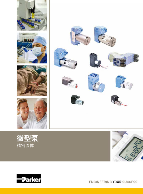
派克精密流体微型泵说明书
您与运动和控制技术领域的先行者合作,就是希望促进您的业务发展和全球的发展。
从微型电磁阀到高集成型自动化系统,我们的产品对于用于药物研发和病原体检测的救生医疗设备和科学仪器至关重要。
并且对于缩短上市时间和降低总体拥有成本也十分关键。
因此,请与派克合作,准备改变这一切吧!/precisionfluidics 1 603 595-1500目录页T2-05Helix124高效和紧凑型 13.5mm 宽泵 – 高达 800 mLPM高压泵 – 超过5.5 LPM 和高达100 PSI 的压力T2-0320高性能与尺寸比率泵 – 高达2.5 LPMLTC 系列76液体系列传送泵 – 高达 650 mLPMEZ 底座92振动隔离安装系统小型活塞泵(空气)微型泵(空气/气体)微型泵(液体)T2-0494超紧凑型、高效泵 – 高达 7.5LPMBTC-IIS 系列62应用广泛的多功能双头泵系列产品 – 高达 11 LPMBTC 系列52应用广泛的多功能泵系列产品 – 高达6 LPMLTC-IIS 系列84液体系列双头传送泵 – 高达1.5 LPMCTS 系列BTX-Connect 2836高性能紧凑型 20 mm 宽泵 – 高达 2.5 LPM多功能双头和单头泵系列,适合多种应用-高达10 LPMTTC 系列74紧凑、高效、低压泵 – 高达 6 LPMTTC-IIS 系列84紧凑、高效、低压双头泵 - 高达 11 LPM附件4Helix 微型高压泵高达100 PSI (6.9 bar)压力Parker Helix 是一款紧凑型高压泵,旨在实现小型即时临床护理仪器。
Helix 可在挑战性的高海拔环境和无法使用外部压缩空气的应用中实现高压操作。
Helix 泵可提供5.5 LPM 以上的流量和高达100 PSI (6.9 bar)的压力,为性能至关重要且空间有限的台式诊断设备提供了出色的解决方案。
• 集成了用于卸荷的X 阀,可实现高压重启• 内部飞轮可在高压下低速运行• 无油活塞• 简单的安装特性• 带有推入式接头的快速流体连接• 符合RoHS 指令和REACH 标准产品特性• 液上空气• 气动驱动•微流控芯片• 即时临床护理检验• 分子诊断• 核酸纯化•基因组学典型应用典型市场产品规格物理特性电子5微型隔Helix 微型高压泵典型流量曲线• 曲线展示了0.080"偏移泵的流量性能• 使用5.0 Vdc 控制输入时,泵将以大约4400 RPM 的转速和高达8.5 LPM的流量的状态运行,但不建议连续工作。
2020年螺杆泵泵国内十大品牌排行榜

2020年螺杆泵泵国内十大品牌排行榜1.上海阳光泵业制造有限公司上海阳光泵业是集设计/生产/销售泵、给水设备及泵用控制设备于一体的大型综合性泵业集团,是中国泵行业的龙头企业。
总资产达38亿元,在上海、浙江、河北、辽宁、安徽等省市拥有7家企业,5个工业园区,占地面积67万平方米,建筑面积35万平方米。
上海阳光获得了“上海市质量金奖”、“上海市科技百强企业”、“上海市名牌产品”、“中国质量信用AAA 级”、“全国合同信用等级AAA级”、“质量、信誉、服务三优企业”、“中国最具竞争力的商品商标”、“五星级服务认证”等荣誉,连续多年入选全国机械500强。
高端人才和高素质的员工队伍是阳光发展的动力。
集团现有员工4500余人,其中工程技术人员500多名,主要由国内知名水泵专家教授、博士硕士、中高级工程师、高级工艺师组成,形成了具有创新思维的梯队型人才结构。
科技创新,是阳光基业长青的生命之源。
集团是上海市高新技术企业、上海市知识产权示范企业和上海市专利示范企业。
上海市级的“企业技术中心”,每年以销售总额的5%,用于技术创新和新产品研发。
2.上海科雷流体自控设备制造有限公司~上海科雷流体自控设备制造有限公司是国内一家集研制、开发、生产、销售、服务于一体的企业,坐落于美丽的东方国际大都市上海。
公司主要产品有系列无负压供水设备.全自动智能成套给水设备.各式水泵.控制柜.污水提升设备及油水分离设备等各产品经国家相关产品检测中心检测都已到达国家相关标准。
公司将继续保持和发扬企业的优良传统秉着"诚信.务实.专业.创新"的经营理念真诚希望与各界精英精诚合作携手共进共创辉煌!3.北京润弘伟业科技有限公司北京润弘伟业科技有限公司是一家从事纯进口高端污水提升系统及污水泵的专业性企业。
产品及服务涵盖别墅污水提升装置、会所污水提升装置、酒店污水提升装置、办公楼污水提升装置、商chang污水提升装置、机场、地铁污水提升装置、市政小区污水提升泵站等领域。
SWIRLFLO 冷水泉源与 FLEXI-GUARD 和 ezH2O 瓶子填充器说明书
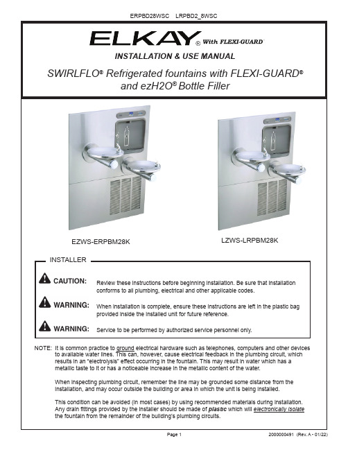
INSTALLATION & USE MANUALSWIRLFLO® Refrigerated fountains with FLEXI-GUARD NOTE: It is common practice to ground electrical hardware such as telephones, computers and other devices to available water lines. This can, however, cause electrical feedback in the plumbing circuit, whichFigure 4 - Fountain InstallationFigure 5 - Lower Panel Installation8. Install fountains with (8) 5/16-18 HHMS & (8) 5/16-18 nuts (provided) (Fig. 4). Connect the ¼” water lines from each fountain to the remaining openings on the tee at the remote chiller (cut lines to fit as needed).9. Attach waste tubes (1-1/4” O.D.) to 1-1/4” O.D. slip trap. Trap on the bottle filler side must be 1-1/2” O.D. (provided by others).10. Make final water supply connections.11. These products are designed to operate on 20-105 PSI supply line pressure. If inlet pressure is above 105 PSI, a pressure regulator must be installed in the supply line.(Caution: Any damage caused by connecting these products to a supply line with pressure lower than 20 PSI or higher than 105 PSI IS NOT covered under warranty.)12. Make electrical connections to the bottle filler and remote chiller. The LCD Bottle counter should illuminate.13. V erify proper dispensing from the bottle filler by placing a cup, hand or any opaque object in front of sensor area and verify water dispenses. Note: the first initial dispenses might have air in the line which may cause a sputter. This will be eliminated once all air is purged from the line. A steady stream of water assures all air is removed. The sensor has a 20 second maxi mum ON time. It may be necessary to step away from the beam a few times to purge all air. Check for leaks.14. Check stream height from bubbler. Stream height is factory set for 35 PSI supply. If supply pressure varies greatly from this, remove push button (Item 7 - Fig. 8) and adjust the screw on the regulator (Item 8 - Fig. 8). To remove push but ton, remove setscrew from bottom of sleeve (Item 21). Insert a small punch in screw hole and push up while grasping the push button and pull forward removing the push button. Clock wise adjustment will raise stream height and counterclockwise movement will lower stream height. For best adjustmentstream should hit basin approximately 6-1/2” from the bubbler. Reassemble the push button by pushing in on button until the push button catches in the sleeve. Reinstall the setscrew (Item 21) in the sleeve (Item 6). 15. Install the cover plates.16. Install the bottom panel, tighten screws (Fig. 4).17. Optional: Mount optional panels. Slide tongue of panel under edge of already installed panel. Tighten screws.201817162423View From Rear5NOTE:When installing replacement bubbler and pedestal (Fig. 6), tighten locknut only to hold parts snug in position. Do Not overtighten.Figure 6 - Flexi-Guard ®Bubbler DetailsBasin 1Locknut2326Reset SwitchBack Panel28,29,30,31,32Figure 7 - Fountain Body AssemblyFigure 8 - Push Button Assembly67821293121941052222See Fig. 6MAIN BOARDI.R. BOARDLED BOARDFOUR PIN CONNECTORFIVE PIN CONNECTORVERIFY CONTROL BOARD SOFTWARE1) To verify the software program of the control board the unit willneed to be shut down and restarted. The chiller (if present) does not need to be shut down and restarted.2) Shut down the unit by unplugging the power cord from the walloutlet or switching off the circuit breaker to the unit.3) R estart the unit by plugging the power cord back into the walloutlet or by switching on the circuit breaker to the unit.4) Upon start up, the bottle count display will show the softwaredesignation of BF11 or BF12.ACCESSING THE PROGRAMMING BUTTON1) To access the program button, remove #8-32 screw, pull backcover plate on lower fountain arm (Fig. 4). Reset button is located above fountain arm.RESET THE FILTER MONITOR1) Instructions apply to filtered units only.2) Depress the program button for approximately 2 seconds untilthe display changes then release. The display will change andscroll through two messages:“RST FLTR” – Reset Filter Monitor“SETTINGS” – System Settings Sub MenuIf the program button is not pushed again the display will scrollthrough the two messages above for three cycles and then default back to bottle count and be back in run mode.3) When the display changes to “RST FLTR”, depress the buttonagain. The display will change to show “FLTR =”. Depress thebutton again and the display will show “FLTR =0”4) The Green LED should be illuminated indicating that the visualfilter monitor has been reset.SETTING RANGE OF THE IR SENSOR WHERE APPLICABLE 1) Depress the program button for approximately 2 seconds untilthe display changes then release. The display will change andscroll through two messages:“RST FLTR” – Reset Filter Status LED“SETTINGS” – System Settings Sub MenuIf the program button is not pushed again the display will scrollthrough the two messages above for three cycles and then default back to bottle count and be back in run mode.2) When the display changes to “SETTINGS”, depress the buttonagain. The display will change to show“RNG SET” - Range set for IR sensor.“UNIT TYP” - Type of unit (REFRIG or NON-RFRG)“FLT SIZE” - Select filter capacity“RST BCNT” - Reset bottle count3) W hen display shows “RNG SET” push program button once the display will show current value (can be 1 – 10) e.g. “RNG = 3”.4) Once display shows current value push the program button toscroll through value of 1 – 10. Select the desired range setting, "1" being closest to sensor and "10" being farthest away.5) Once range is selected allow approximately 4 seconds to pass and then the display will go back to bottle counter and be in run mode.6) T est bottle filler by placing bottle or hand in front of sensor tomake sure water is dispensed.SETTING UNIT TYPE1) Depress the program button for approximately 2 seconds until the display changes then release. The display will change and scroll through two messages:“RST FLTR” – Reset Filter Status LED“SETTINGS” – System Settings Sub MenuIf the program button is not pushed again the display will scrollthrough the two messages above for three cycles and then default back to bottle count and be back in run mode.2) When the display changes to “SETTINGS”, depress the button again.The display will change to show“RNG SET” - Range set for IR sensor.“UNIT TYP” - Type of unit (REFRIG or NON-RFRG)“FLT SIZE” - Select filter capacity“RST BCNT” - Reset bottle count Continued from below:3) W hen display shows “UNIT TYPE” push program button once thedisplay will show current value. C an be REFRIG or NON-RFRG4) Push button once to change value. Once value is s elected the display will show the new value. (Can be REFRIG or NON-RFRG) “REFRIG“ - stands for refrigerated product. In this setting the flow rate is estimated at 1.0 gallon per minute.“NON-RFRG“ - stands for nonrefrigerated product. In this setting theflow rate is estimated at 1.5 gallons per minute. Both “REFRIG“ and“NON-RFRG“ simulate 1 bottle equal to 20 oz.5) A llow approximately 4 seconds to pass and the display will return to bottle counter and be in run mode.RESETTING BOTTLE COUNT1) Depress the program button for approximately 2 seconds until thedisplay changes then release. The display will change and scrollthrough two messages:“RST FLTR” – Reset Filter Status LED“SETTINGS” – System Settings Sub MenuIf the program button is not pushed again the display will scroll through the two messages above for three cycles and then default back to bottle count and be back in run mode.2) When the display changes to “SETTINGS”, depress the button again. The display will change to show:“RNG SET”- Range set for IR sensor.“UNIT TYP” - Type of unit (REFRIG or NON-RFRG)“FLT SIZE” - Select filter capacity“RST BCNT” - Reset bottle countIf the button is not pushed again the display will scroll through the four messages above for three cycles and return to run mode.3) W hen display shows “RST BCNT” push program button once thedisplay will show current value, e.g. “0033183”.4) Once display shows current value push the program button once more to reset back to 0. The display will show BTLCT = 0 for approximately 2 seconds and then return to run mode showing 00000000 bottles. NOTE: Once the bottle count is reset to zero there is no way to return to the previous bottle count.5) T esting the bottle counter:REFRIG units: Place bottle or hand in front of sensor for approximately9 seconds to see bottle counter count 00000001,(This is based on filling a 20 oz. bottle).NON-RFRG units: Place bottle or hand in front of sensor for approximately 6 seconds to see bottle counter count 00000001,(This is based on filling a 20 oz bottle).SETTING FILTER CAPACITY1) Depress the program button for approximately 2 seconds until thedisplay changes then release. The display will change and scroll through two messages:“RST FLTR” – Reset Filter Status LED“SETTINGS” – System Settings Sub MenuIf the program button is not pushed again the display will scroll through the two messages above for three cycles and then default back to bottle count and be back in run mode.2) When the display changes to “SETTINGS”, depress the button again. The display will change to show:“RNG SET“- Range set for IR sensor.“UNIT TYP“ - Type of unit (REFRIG or NON-RFRG)“FLT SIZE” - Select filter capacity“RST BCNT“ - Reset bottle countIf the button is not pushed again the display will scroll through the four messages above for three cycles and return to run mode.3) W hen display shows “FLT SIZE” push program button once. The display will show current value. Can be 3000GAL or 6000GAL.4) Push program button again to display the desired “FLT SIZE”.5) Allow approximately 4 seconds to pass and the display will return tobottle counter and be in run mode.BF11 - BF12 PROGRAM SETTING THE CONTROL BOARDMOUNTING FRAMEMAIN PANELDRAINLOCATIONSLOWER PANELREMOTE CHILLERFILTER (OPTIONAL)MOUNTINGFRAME Figure 9Fig. 103/8”Water InletFilter Head Assembly used after 01/01/202121JUNCTIONBOX27NOTE: Bottle filler back cover removed from the view for clarityWATERSENTRY ® PLUS FILTER PARTS LIST(See Fig. 10)ITEM NO.PART NO.DESCRIPTION1251300C 51469CFilter Assy-3000 Gal.Assy-Filter & Brkt includes Fltr Head/Mtg Brkt/John Guest Fittings/Screws1Figure 11 – Water Supply ConnectionsStream Regulator: flow as in Step 14 of the installation instructions. If NOTE: WATER FLOWDIRECTION SERVICE STOP (NOT FURNISHED)23456756073C 28708C 28473C 45767C 28343C 45781C 98871C Kit - Bubbler Assy Basin - Swirlflow Lower Shell Fountain Body Cover Plate SleeveKit - Swirlflo Pushbutton/Spring PARTS LISTITEM NO.PART NO.DESCRIPTION。
ALL-FLO气动隔膜泵A200-BAA-SSPE的技术特点
奥弗ALL-FLO隔膜泵的技术特点:
苏州埃立特流体设备有限公司专业为客户提供高品质进口化工泵。
1.全塑料材质的气阀结构,无任何金属材质部件,无需担心膜片破损造成流体腐蚀气阀部件的现象;
2.独特的气阀设计结构,无需担心因压缩空气不干净而导致停机;
3.由自润滑材质做成的梭式机械结构主气阀,摩擦系数小,无需添加任何润滑油;
4.无通风孔设计的气阀系统,避免了腐蚀性气体造成的气阀腐蚀,且保证运行畅通无死点;
5.高技术的密封,在不干净及较湿的气体进入时,气阀仍然可以工作。
使用唇封技术及高耐磨性橡胶大大延长了使用寿命;
6.选用更优质的PTFE材质隔膜,不需要降低隔膜的冲程次数,从而损失20%的流量,而其他品牌都需这么做。
且所以PTFE隔膜的背衬隔膜都是Santoprene 材质,同样具有抗腐蚀性,被称为“二级防护”。
美国IDEX泵业集团帕斯菲达公司 Chem-Tech 隔膜计量泵 说明书

Chem-Tech 隔膜计量泵
使用说明书
帕斯菲达计量泵
本篇中文稿仅供使用者参考,如有理解歧义,请以英文原稿为准。
1
目录
页数
安全说明…………………………………………………………………………… 1-2 介绍………………………………………………………………………………… 2 操作前准备………………………………………………………………………… 3 安装、布管、连接………………………………………………………………… 3-7 维护………………………………………………………………………………… 8 服务和维修………………………………………………………………………… 9 问题检修…………………………………………………………………………… 10-11 零件目录表………………………………………………………………………… 12 置换备件包………………………………………………………………………… 13
安装,管道和线路
拆卸,装配和安装
纸箱中应包含(见图 A): -- 计量泵 -- 透明吸液管 -- 白色硬回溢流管 -- 白色硬排液管 -- 注入背压阀 -- 粗滤止逆底阀 / 配重块 -- 说明书 -- 排出阀配件 -- 三通阀
图A
4
进料器可以安装在墙上的托架上(图 B),槽架平台上(图 C),垂直于墙面(图 D),或垂直于 槽表面(图 E)。 提示:连接点必须高于溶液槽的顶部,这样可阻止因重力进料。100 系列泵的最大扬程为 70M,
5
注意:对于无排出阀操作,补充排出阀(#49 款)和 0.38"管卸压阀罩(#42 款)带 0.5" 管卸压阀罩(#42 款)和接合螺母(#43 款)。看 13 页(铜网部装配)。#42 和#43 从工厂索取。
安德里兹sf浆泵说明书

2.1. 技术说明______________________________________________________________ 11 2.1.1. 形式 _____________________________________________________________________ 11 2.1.2. 叶轮 _____________________________________________________________________ 11 2.1.3. 轴承 _____________________________________________________________________ 11 2.1.4. 轴密封 ___________________________________________________________________ 11 2.1.5. 材料 _____________________________________________________________________ 11 2.1.6. 部件清单 SF 100-250________________________________________________________ 12 2.1.7. 部件清单 SF 125-280________________________________________________________ 14 2.1.8. 部件清单 SF 100-350________________________________________________________ 16 2.1.9. 部件清单 SF 150-300________________________________________________________ 18
ALL-FLO操作手册1

ALL-FLO隔膜泵操作手册第一部分:注意事项—必先阅读各种材质耐温极限:接液部件:聚丙烯(PP)聚偏二氟乙烯(PVDF)导电尼龙(Conductive Nylon)0℃~ 65℃-12℃~93℃-17℃~ 65℃32℉~150℉10℉~225℉0℉~150℉尼龙(Nylon)弹性体:-12℃~ 65℃10℉~150℉三道橡胶(Santoprene)氟橡胶(Viton)Geolast®聚四氟乙烯/特氟龙三元乙丙橡胶(EPDM)-12℃~ 100℃-4℃~100℃-12℃~82℃4℃~100℃-40℃~100℃10℉~212℉-20℉~212℉10℉~180℉40℉~212℉-40℉~212℉*通过选择不同的弹性体可以改变温度限度。
注意:当选择泵的材质时,一定要检查所有接液部件的温度限度。
如氟橡胶的最高温度限度为100℃(212℉),而聚丙烯的最高温度限度只有65℃(150℉)。
注意:操作泵的时候需配带安全防护眼镜。
当发生膜片碎裂时,可能会从气体出口冲出。
警告:防止静电火花——如果有静电火花产生,有可能会引起火灾或爆炸。
当输送的易燃性液体无论何时都有可能释放静电时,泵、阀及容器的正确接地就变得至关重要了。
注意:ALL-FLO全系列的隔膜泵,供气压力不得超过8.2bar(120psig)。
注意:ALL-FLO的聚丙烯(PP)塑料泵是由天然聚丙烯制成,应避免长时期的日光照射,否则可引起塑料的降解。
第二部分:安装及操作A.安装:①进行维护与检修前,应拆除连于泵上的压缩气体管道并将泵内所有的气体排出。
拆开所有入口、出口及空气管道,将泵倒置并用适宜容器盛装泵内流出的液体。
②在安装空气管道之前,最好用压缩空气将管道吹10至20秒以保证所有的管道碎片均被除净,且最好在隔膜泵泵的压缩空气入口加装空气两联件(调压、过滤),最好保证过滤精度大于25微米。
③安装前旋紧所有的螺栓,因为在运输过程中安装好的螺栓有可能会松动。
无锡中康流体科技有限公司 E,CE 系列端吸离心泵 安装、操作及维护手册说明书
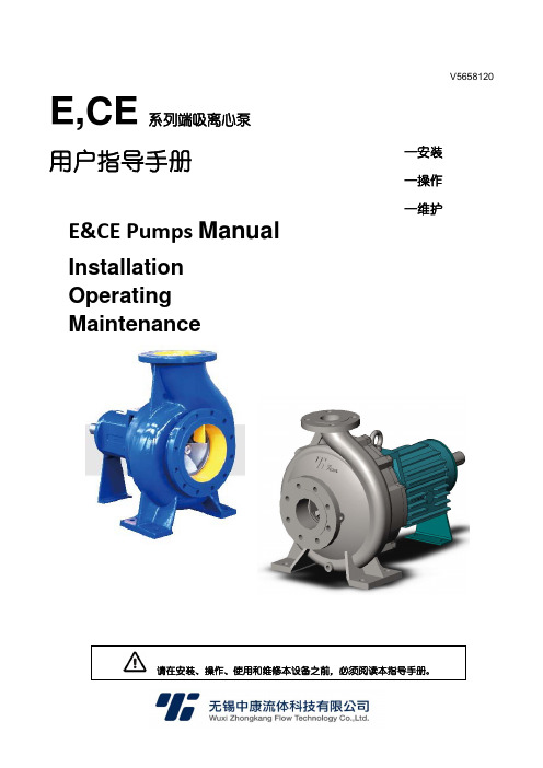
V5658120E,CE系列端吸离心泵用户指导手册E&CE Pumps ManualInstallation Operating Maintenance请在安装、操作、使用和维修本设备之前,必须阅读本指导手册。
—安装 —操作 —维护E,CE系列端吸离心泵安装、操作及维护手册目录1概要 (5)1.1注意事项 (5)1.2 免责声明 (5)1.3保证 (5)1.4 安全 (5)2运输和存放 (5)2.1货物接收和拆包 (5)2.2吊运 (6)2.3 储存 (6)3产品介绍 (7)3.1型号说明 (7)3.2结构 (7)3.3性能 (7)4 安装 (7)4.1 安装位置 (7)4.2 零件装配 (7)4.3灌浆 (8)4.4联轴器对中 (8)4.4.1检查和调整对中的要点 (8)4.4.2对中测量方法 (8)4.5管道连接 (9)4.5.1吸入管道 (9)4.5.2排出管道 (9)4.5.3辅助管道 (9)4.5.4 最终检查 (10)4.6 最终轴对准检查 (10)4.7 电气连接 (10)5 试车、启动、运行和停机 (10)5.1 试车前步骤 (10)5.1.1 润滑 (10)5.1.2旋转方向 (10)5.2启动泵 (10)5.3运行泵 (11)5.4 停止和关机 (11)6 维护及维修 (11)6.1概述 (11)6.2 检查计划 (11)6.2.1 例行检查(每日/每周) (11)6.2.2 定期检查(每6个月) (12)6.3 备件 (12)6.3.1 备件订购 (12)6.3.2 备件的存放 (12)6.4 推荐的备件 (12)6.5 所需工具 (12)6.6 紧固件扭矩 (13)6.7 拆卸 (13)6.8 装配 (13)7故障原因及纠正措施 (14)8零件清单及图纸 (15)8.1装配结构图及零件清单 (15)8.2爆炸零件图及零件清单 (16)9增补信息 (17)E,CE系列端吸离心泵安装、操作及维护手册1概要该指导手册必须存放在产品的运行位置附近,或者与产品存放在一起。
蓝白工业有限公司FLEXFLO模型压力类型动力机械的产品说明说明书

Max. working pressure:........100 psig (6.9 bar)o o Max. fluid temperature:........130 F (54 C)o o o o Max. ambient temperature:..14 to 110 F/ -10 to 43 C Output adjustment range:....5-100% in 1% increments Duty cycle:.............................ContinuousMaximum viscosity:..............5,000 Centipoise Maximum suction lift:...........30 ft. Water 0 psig Maximum Solids:..................50% by volumeEnclosure:.............................NEMA type 2, (IP21)!!!!!!!!Peristaltic pump design does not have valves that can clog requiring maintenance.Self priming - even against maximum line pressure. By-pass valves are not required. Cannot vapor lock or lose prime.Outputs to 250 ml/min (95.1 GPD).Output pressures to 100 PSI.Output volume is not effected by changes in back pressure.Patented pump tube design installs easily and stays centered on the rollers without manual adjustment.Two pump tubes supplied with each pump. No extra tubing required.Accepts 4-20mA, 0-10Vdc, and Pulse inputs for manual or external speed control.Blue-WhiteRq !!!!Operator friendly digital touch pad.--Easy to read LCD display--Service and Alarm indicator icons.--Display motor speed or input signal values.--Prime mode for easy priming without changing programming.Built-in Tube Failure Detection system (TFD). Senses chemical in the pump head, shuts off the pump and activates a 1 amp alarm relay (dry contact closure).Compatible with Blue-White’s output flow verification sensor system.Durable housing of chemical resistant Valox (PBT) thermoplastic.Specifications:Voltage (amp draw):..............115VAC/60Hz, 1ph (.350 amp max) 230VAC/60Hz, 1ph (.173amp max) 220VAC/50Hz, 1ph (.175amp max) 240VAC/50Hz, 1ph (.193amp max)Power Cord Plug Type:.........115V60Hz = NEMA 5/15 (USA) 230V60Hz = NEMA 6/15 (USA) 220V50Hz = CEE 7/VII (EUROPE) 240V50Hz = CEE 7/VII (U.K)Approximate shipping wt: ...12 lb. (5.4 kg)Materials of Construction:Wetted components:q Pump Head & Enclosure:.....Valox (PBT) thermoplastic Pump Head Cover:................Clear PVCCover Screws:.......................300 Stainless, Polypropylene cap Roller Assembly:q Rotor:..................................Valox (PBT)Rollers:...............................Nylon Roller Bearings:.................BronzeMotor Shaft:...........................Nickel plated steel TFD System Sensor pins:....Hastelloy C-276Power Cord:..........................3 conductor, SJTW-A Water-resistantNon-Wetted components:systemTFD Tube Failure DetectionqqqPump Tube Assembly:..........Norprene ,Tygothane or Viton tubing PVDF tube assembly connection fittings Suction Tubing:.....................Clear PVCSuction Strainer:...................Natural PolypropyleneDischarge Tubing:.................Natural Polyethylene (LLDPE)Injection/Check valve:Body & insert:....................Polypropylene (optional PVDF)Check Ball:.........................CeramicSpring:................................Hastelloy C-276Ball Seat O-ring:.................TFE/P (optional EP)q Static Seal O-ring:..............Viton (optional EP)Blue-Whiteq FLEXFLO Peristaltic Metering PumpsDimensions:4 placesBase MountingRear Panel Mounting.200 Dia.2 placesModel Number Matrix:MODEL A1NMaximum Motor RPM 0 = 14 RPM 1 = 30 RPM 2 = 45 RPM 3 = 60 RPM Power Supply 0 = 115V60Hz 1 = 220V50Hz 2 = 230V60Hz 8 = 240V50HzOutput ControlV = Digital speed control with external input F = Analog speed controlE = Digital batch timer with external input A = Analog timer, 60 sec. Cycle - 100% duty C =Analog timer, 5 sec. Cycle - 100% duty S = Analog timer, 60 sec. Cycle - 10% duty Z = Proportional feed system - JBox/Cord X = No output control - fixed feed rateTubing Connection Type T = Compression tube nuts Q = Push-on quick connect Miscellaneous Options (not required)1 = TI40-6V injector replaces A-014HD-6A2 = C-340V footvalve replaces C-342-6 strainer 5 = A-014HDK-6A injector PVDF T7 = 7 gallon chemical tank system T15= 15 gallon chemical tank system T30 = 30 gallon chemical tank system --V 5300 Business Drive,Huntington Beach,CA 92649Tel: 714-893-8529Fax: 714-894-9492 Email:********************Technical data sheet #85000-040 rev.051305All trademarks are the property of their respective owners.14 RPM MODELSTubing Material Tygothane Tygothane Tygothane Norprene Viton Norprene Norprenegpd 5.712.227.82.34.26.821.7oz/min 0.511.082.470.200.370.611.92ml/min 1532736111857gph 0.240.511.160.100.170.290.90Maximum Flow rate and pressure capacities:Replacement Pump Tubes:Pump Tube Part NumberA-002N-1T A-002N-2T A-002N-3T A-002N-4T A-002N-5T A-002N-6T A-002N-7T A-002N-1Q A-002N-2Q A-002N-4Q A-002N-6QNominal Pump Tube OD1/4”3/8”7/16”1/4”5/16”3/8”7/16”1/4”3/8”1/4”3/8”Pump Model Number Suffix-1T -2T -3T -4T -5T -6T -7T -1Q -2Q -4Q -6QTube no.1234567PSI656550100251005030 RPM MODELSgpd 13.328.565.84.99.916.052.5oz/min 1.182.545.850.440.881.424.66ml/min 3575173132642138gph 0.551.192.740.210.410.672.19PSI656550100251005045 RPM MODELSgpd 20.543.799.28.014.824.076.1oz/min 1.833.898.820.201.312.136.76ml/min 54115261213963200gph 0.861.824.140.100.621.003.17PSI656550100251005060 RPM MODELSgpd 25.553.2124.09.518.330.095.1oz/min 2.264.7311.010.851.622.678.45ml/min 67140326254879250gph 1.062.225.170.400.761.253.96PSI65655075257550Pump Tube MaterialTygothane Tygothane Tygothane Norprene Viton Norprene Norprene Tygothane Tygothane Norprene NorprenePump Tube Size and Material 1= 1/4” OD Tygothane 2= 3/8” OD Tygothane 3= 7/16” OD Tygothane 4 = 1/4” OD Norprene 5 = 5/16” OD Viton 6 = 3/8” OD Norprene 7 = 7/16” OD Norprene。
2020年中国化工泵品牌影响力总评榜
2020年中国化工泵品牌影响力总评榜1.上海阳光泵业制造有限公司上海阳光泵业是集设计/生产/销售泵、给水设备及泵用控制设备于一体的大型综合性泵业集团,是中国泵行业的龙头企业。
总资产达38亿元,在上海、浙江、河北、辽宁、安徽等省市拥有7家企业,5个工业园区,占地面积67万平方米,建筑面积35万平方米。
上海阳光获得了“上海市质量金奖”、“上海市科技百强企业”、“上海市名牌产品”、“中国质量信用AAA 级”、“全国合同信用等级AAA级”、“质量、信誉、服务三优企业”、“中国最具竞争力的商品商标”、“五星级服务认证”等荣誉,连续多年入选全国机械500强。
高端人才和高素质的员工队伍是阳光发展的动力。
集团现有员工4500余人,其中工程技术人员500多名,主要由国内知名水泵专家教授、博士硕士、中高级工程师、高级工艺师组成,形成了具有创新思维的梯队型人才结构。
科技创新,是阳光基业长青的生命之源。
集团是上海市高新技术企业、上海市知识产权示范企业和上海市专利示范企业。
上海市级的“企业技术中心”,每年以销售总额的5%,用于技术创新和新产品研发。
2.南京赛莱默有限公司Xylem公司简介及品牌优势Xylem集团是一家大型跨国工程技术和制造公司,成立于1901年,距今已有107年的历史,是世界工业500强之一。
Xylem集团公司总部设在美国纽约白滩(WhitePlains),在全球135个国家设有274家生产基地和研发机构,全球拥有40000多员工。
在流体技术领域,Xylem集团是全球公认的最大的泵类产品和流体技术产品制造商,年销售额远远*于其他竞争对手。
除纽约股票交易所外,Xylem集团公司的股票还在中西部证券交易所,太平洋股票交易所,巴黎和法兰克福股票交易市场上市。
并同时入选标准普尔500股价指数(SP500Index)。
Xylem国际集团公司卓越的社会价值和经济价值赢得了业界广泛的关注与认可,《财富》杂志一直将其列入最受推崇的企业排名榜;同时被《商业道德》杂志列入百佳企业公民排名榜,并连续4年入选道琼斯可持续发展世界指数(DJSI)。
3A6850H电动泵产品说明书
3A6850HZH安装 - 零件E-Flo ®SP 电动泵用于密封剂和黏合剂用于单组分密封剂和粘结材料。
仅适用于专业用途。
未获准用于易爆或危险环境场所。
有关的型号资料,包括最大工作压力和核准使用情况,请参见第 3 页。
重要安全说明请在使用该设备之前,阅读本手册以及相关手册内所有的警告和说明内容。
保存所有说明。
相关手册23A6850H目录相关手册 . . . . . . . . . . . . . . . . . . . . . . . . . . . . . . . . . . 2型号 . . . . . . . . . . . . . . . . . . . . . . . . . . . . . . . . . . . . . . 3系统压力 . . . . . . . . . . . . . . . . . . . . . . . . . . . . . . . 4警告 . . . . . . . . . . . . . . . . . . . . . . . . . . . . . . . . . . . . . . 5部件辨认 . . . . . . . . . . . . . . . . . . . . . . . . . . . . . . . . . . 7带 100 cc Check-Mate CS 下缸体的电动泵 . . . . 7高级显示模块 (ADM) . . . . . . . . . . . . . . . . . . . . . . 8安装 . . . . . . . . . . . . . . . . . . . . . . . . . . . . . . . . . . . . . . 9定位和安装 . . . . . . . . . . . . . . . . . . . . . . . . . . . . . 9接地 . . . . . . . . . . . . . . . . . . . . . . . . . . . . . . . . . . . 9电源要求 . . . . . . . . . . . . . . . . . . . . . . . . . . . . . . . 9连接电源 . . . . . . . . . . . . . . . . . . . . . . . . . . . . . . 10连接独立变压器 . . . . . . . . . . . . . . . . . . . . . . . . . 11在设备使用之前安装开口机油盖 . . . . . . . . . . . . 12流体软管的连接 . . . . . . . . . . . . . . . . . . . . . . . . . 12连接多个泵 . . . . . . . . . . . . . . . . . . . . . . . . . . . . 13设置 . . . . . . . . . . . . . . . . . . . . . . . . . . . . . . . . . . . . . 14湿杯 . . . . . . . . . . . . . . . . . . . . . . . . . . . . . . . . . . 14冲洗泵 . . . . . . . . . . . . . . . . . . . . . . . . . . . . . . . . 14泄压步骤 . . . . . . . . . . . . . . . . . . . . . . . . . . . . . . . . . 16关闭并维护泵 . . . . . . . . . . . . . . . . . . . . . . . . . . . . . . 16驱动器维护 . . . . . . . . . . . . . . . . . . . . . . . . . . . . . . . . 17零配件 . . . . . . . . . . . . . . . . . . . . . . . . . . . . . . . . . . .18带 Check-Mate 下缸体的电动泵 . . . . . . . . . . . .18带 Dura-Flo 下缸体的电动泵 . . . . . . . . . . . . . . .22单向阀 . . . . . . . . . . . . . . . . . . . . . . . . . . . . . . . .25套件及附件 . . . . . . . . . . . . . . . . . . . . . . . . . . . . . . . .28高级显示模块配件包 25E439 . . . . . . . . . . . . . .28通信网关模块 (CGM) 配件包 . . . . . . . . . . . . . . .29入口压力传感器配件包,24Y245 . . . . . . . . . . .30泵架式机架,253692 . . . . . . . . . . . . . . . . . . . .31壁式安装支架,255143 . . . . . . . . . . . . . . . . . .31地板安装适配器,223952 . . . . . . . . . . . . . . . . .32CAN 电缆 . . . . . . . . . . . . . . . . . . . . . . . . . . . . . .32灯塔配件包,255468 . . . . . . . . . . . . . . . . . . . .32I/O 电缆,122029 . . . . . . . . . . . . . . . . . . . . . . .32尺寸 . . . . . . . . . . . . . . . . . . . . . . . . . . . . . . . . . . . . .33E-Flo SP 泵尺寸 . . . . . . . . . . . . . . . . . . . . . . . .33泵机架安装孔图表 . . . . . . . . . . . . . . . . . . . . . . .34地板支脚安装孔图表 . . . . . . . . . . . . . . . . . . . . .35电动驱动器安装孔位置图 . . . . . . . . . . . . . . . . . .35变压器安装孔图表 . . . . . . . . . . . . . . . . . . . . . . .36泵性能 . . . . . . . . . . . . . . . . . . . . . . . . . . . . . . . . . . .37E-Flo SP 性能图表 . . . . . . . . . . . . . . . . . . . . . . .38技术规格 . . . . . . . . . . . . . . . . . . . . . . . . . . . . . . . . . .43美国加州第 65 号提案 . . . . . . . . . . . . . . . . . . . . . . .44Graco 标准保修 . . . . . . . . . . . . . . . . . . . . . . . . . . . .46相关手册这些手册可以从 网站获取。
特芬 Tefen MixRite 水流驱动计量泵 1-60 L h 2-90 L h 操作手册说明书
TRATTAMENTO DELLE ACQUER egolazione della pompaMixRiteIl volume di iniezione viene impostato manualmente ruotando la ghiera nella proporzione desiderata. La quantità di prodotto concentrato iniettato è proporzionale alla quantità di acqua che scorre nella pompaMixRite.Acqua dolceManicottoregolazionedosaggioMotoremiscelatoreTefen dal 1973 è leader nella produzione di miscelatori volumetrici che nonrichiedono energia elettrica per il loro funzionamento e che rispettano l’ambiente.La linea di pompe dosatrici MixRite di Tefen garantisce una precisamiscelazione del prodotto concentrato nella rete idrica o di altri liquidi.È la scelta giusta per molti motivi.Applicazioni■Clorazione■Igienizzazione■Disinfezione dell’acquaLa pompa dosatrice azionata ad acqua MixRite di Tefen è un sistemafacile da usare e ingegnoso che ha dimostrato il suo valore in oltre 90paesi.Tefen è certificata ISO 9001 2015T asso di dosaggioInformazioni su TEFENVantaggi dell’utilizzo di MixRite■Facile installazione■Bassi costi di esercizio e manutenzione■Motore idraulico attivato solo dalla pressione del flusso dell’acqua –non elettrico■Dosaggio proporzionale alla portata■Ripetibilità e omogeneità del dosaggio eccellenti2 | POMPE DOSATRICIClorazione per zone rurali o in casi di emergenza:■Si stima che 2,6 miliardi di persone non abbiano un accesso soddisfacente all’acqua potabile■adatte a condizioni estreme, come la mancanza di elettricità e di vincoli locali■Concentrazione e dosaggio tipici:■Ipoclorito di sodio: 0,3 - 5 PPM■Biossido di cloro: 0,3 – 5 PPM■Perossido di idrogeno: 1 PPM e superiore■Tutti i livelli di concentrazione e dosaggio si riferiscono al contenuto di acqua.Controllo del PH■Per il controllo del pH vi è una vasta gamma di acidi utilizzati, come ad esempio: acido solforico, acido clorico, acido fosforico, acido nitricoIgienizzazione e disinfezioneLe pompe dosatrici proporzionali MixRite sono ampiamente utilizzate per l’igienizzazione e la disinfezione delle reti idriche.Settori che rientrano in questa applicazione:■Trasformazione e igienizzazione dei prodotti agroalimentari■Pulizia delle linee di produzione della birra■Sale operatorie – pulizia e disinfezione delle superfici■Additivi detergenti e igienizzanti da dosare e iniettare, inclusi glutaraldeide e acidi organici come:■acido peracetico, acido formico, ecc.■ammonio quaternario, ecc.ClorazioneProdotti chimici e acidi PVDF34 | POMPE DOSATRICIPompe dosatriciPressione dell’acqua 0,2 – 8 bar Portata 10 – 3.500 L/h Peso 1,8 kg*Attacco3/4”0,03-0,2%, 0,1-0,9%, 0,3-2%, 0,5-5%, 1-10%Pressione dell’acqua 0,2 – 8 bar Portata 7 – 2.500 L/h Peso 1,8 kg Attacco3/4”Portata bassa0,1-0,9%, 0,3-2%, 0,4-4%Pressione dell’acqua 1 – 8 bar Portata 0,05 - 10 m 3/h Peso 7,4 kg Attacco1,5” o 50 mm* Gambe di supporto disponibili su richiesta speciale0,1-1%, 0,2-2%, 1-5%Pressione dell’acqua 1 – 8 bar Portata 0,02 - 5 m 3/h Peso 5 kg Attacco1” o 32 mm* Gambe di supporto disponibili su richiesta speciale0,1-1%, 0,2-2%, 0,5-5%*1-10%: 3 kg5Purificazione dell’acqua potabile6 | POMPE DOSATRICISistema galleggiante percisterne Watch Guard e iniettori ad acqua MixRiteWatch Guard è il primo sistema di diluzione con valvola galleggiante per cisterne progettato per la fornitura di soluzioni diluite in qualsiasi fusto, cisterna o altro tipo di serbatoio. Quando viene collegato ad una fonte idrica standard, Watch Guard si attiva automaticamente e tiene il serbatoio pieno, garantendo una fornitura costante di soluzione diluita per il sistema MixRite.Gli iniettori ad acqua MixRite si collegano in linea alla rete idrica e utilizzano la pressione dell’acqua p e r m i s c e l a r e a c c u r a t a m e n t e l e s o l u z i o n i indipendentemente dalle variazioni di flusso o di pressione.Utilizzando Watch Guard in combinazione con qualsiasi sistema MixRite è possibile ottenere diluzioni elevate, fino a 5 parti per milione.■Consente di ottenere una diluzione elevata in 2 semplici passi■delle sostanze chimiche■Watch Guard è semplice da installare su qualsiasi fusto, cisterna o altro serbatoio■Si attiva automaticamente per mantenere il serbatoio pieno di soluzione miscelata■Punta di misurazione inclusa per le diluzioni da 0,25% a 14,2%■Comprende un dispositivo di ritegno per i divari di azione approvato ASSE 1055B■MixRite si collega in linea alla rete idrica■Fornisce un dosaggio accurato indipendentemente dal flusso d’acqua o dalle variazioni di pressione ■Diversi modelli disponibili per volumi di dosaggio dall’1% al 10% e portate d’acqua da 227 a 25.000 litri all’oraDiluzioni elevateMixRite+=AcquaDiluzione fino a 5 PPMDiluzione 0,25%-14,2%AcquaQualsiasi acido concentrato, cloro o sostanza chimicaDA NON SCALARE(Serbatoio per la soluzione diluita)PUNTA DI MISURAZIONE7Rapporti di induzione per le viscosità mostrateRapporti di diluzione di MixRite in combinazione con l’unità Watch Guard8 | POMPE DOSATRICISistema di bypass proporzionale e automaticoIl sistema TreatRite™ fornisce un metodo proporzionale tra la linea principale (A) e la sotto-linea (B), supportato da un sofisticato sistema idraulico innovativo. La pompa MixRite™ è un’unità volumetrica proporzionale. La combinazione di pompa dosatrice MixRite™ e unità bypass crea un sistema di dosaggio completamente proporzionale. Questo sistema fornisce pertanto all’utente una soluzione perfetta per il trattamento delle acque. L’utente finale del sistema TreatRite™ può dosare i comuni additivi per il trattamento delle acque, come ad esempio: ipoclorito di sodio, biossido di cloro e perossido di idrogeno. Il sistema TreatRite™ può essere utilizzato a diversi intervalli, come riportato qui di seguito:– Linea di trattamento delle acquePerdita di pressione vs. portata5,00,000,400,801,201,6015,025,035,045,055,065,075,085,095,0P e r d i t a d i p r e s s i o n e (b a r )Portata della linea principale (m 3/h)2"3"4"AB90%10%9Gamma :Principio di funzionamento■La valvola di comando pilota rileva il livello dipressione in più punti e controlla la condizione di apertura del diaframma.■Questa operazione regola le portate per generare un rapporto stabile 1:10 tra le linee.Caso di studio (trattamento delle acque)■Portata totale dell’acqua: 67,3 m 3/h ■Tasso di dosaggio desiderato: 0,1%■Quantità dell’additivo: 67,3 x 0,1% = 0,0673 m 3/h Configurazione rilevante: 4’’, 1,5"■Flusso dell’acqua della linea principale: 67,3 x 0,9 = 60,57 m 3/h■Flusso dell'acqua del bypass: 67,3 x 0,1 = 6,73 m 3/h Iniettore rilevante: TF10 0,2%-2%■Impostazione del dosaggio sull’iniettore: 0,0673 / 6,73 = 1%Caratteristiche e vantaggi■Mantiene costante la portata proporzionale ■Idraulico, volumetrico e non elettrico ■Dosaggio proporzionale alla portata■Precisione: qualità in superficie ottimizzata, senza sprechi■Ad ampie portate, la portata tra la linea principale e la linea secondaria rimane 10:1 ■Pressione operativa fino a 8 bar ■Elevata resistenza ai raggi UV ■Elevata resistenza chimica■Sistema preimpostato. Nessuna calibrazione necessaria■Ripetibilità e omogeneità del dosaggio eccellenti■Di facile installazione, utilizzo e manutenzione, senza rischi elettriciTF-52.53.5TF-10Trattamento delle acqueCon trattamento delle acque si intende qualsiasiprocesso volto a migliorare la qualità dell’acqua perrenderla più idonea a uno specifico uso finale. L’usofinale può essere: produzione di acqua potabile,fornitura di acqua a uso industriale, irrigazione,manutenzione dei flussi fluviali, ricreazione delle acquee molti altri usi, compresa la reimmissione sicuranell’ambiente.Tefen Flow Products è uno dei principali fornitori diprodotti per tubazioni industriali a livello mondialeper soddisfare le esigenze di impianti idrici e didepurazione. Il sistema di Tefen, superiore allaconcorrenza, è composto da raccordi, valvole e tubie garantisce prestazioni uniformi in tutti gli impianti ditrattamento Le proprietà non corrosive garantisconobuone prestazioni sul lungo periodo e bassi costi dimanutenzioneI prodotti Tefen Flow sono certificati NSF e hannoconseguito l’approvazione WRAS.10 | POMPE DOSATRICI11RACCORDI IN PVDFPRE-FILTRO DELL’ACQUAVALVOLETEFEN LTD.KibbutzNahsholim3081500Israele|Tel.97246395944|Fax.97246390813|********************| E D I T I O N 0 4 I T 0 4 / 2 0 2 0 n o w -b r a n d i n g . c o . i le/o le specifiche tecniche dei prodotti e/o aggiungere e/o rimuovere prodotti e/o modificare i prezzi e/o i termini e le condizioni specificati nel presente documento in qualsiasi momento e a sua esclusiva discrezione, senza alcun preavviso.。
FAST-FLO
指示-部分Fast-Flo®空气电动机3A8628W ZH 215963型,A系列,101.6mm(4in.)冲程重要安全说明请阅读本手册中的所有警告和说明。
妥善保存这些说明。
最大空气工作压力12.5bar(1.25MPa,180psi)。
注意:要更换215963空气电动机,请订购电动机更换套件223099。
有关零件的详细信息,请参见手册307977。
PROVEN QUALITY.LEADING TECHNOLOGY.Contents警告 (3)安装 (5)接地 (5)泵接地 (5)操作 (6)泄压步骤 (6)故障排除 (7)维修 (8)空气活塞和下部弹簧维修 (8)密封圈更换 (8)上部弹簧更换 (8)清洁消声器 (8)零件 (10)尺寸 (12)技术数据 (13)固瑞克标准保修 (14)23A8628W警告警告以下警告适用于此设备。
惊叹号标志表示一般性警告,而各种危险标志则表示与特定的操作过程有关的危险。
当本手册正文中或标志上出现这些符号时,请参阅此页中的这些警告。
并未包含在本章节内的针对产品的危险符号及警告,可能在本手册内适当的章节出现。
3A8628W3警告警告皮肤注射危险从喷枪、泄漏处、或破裂的部件喷出的射流,会将液体注入身体,导致非常严重的损伤,甚至需要进行截肢手术。
溅入眼睛的液体或落在皮肤上的液体页可引起严重受伤。
•液体注入皮肤可能看上去像割伤一样,但这是很严重的受伤。
应应即刻进行手术治疗。
•不要将喷枪指着任何人或身体的任何部位。
•不要将手或手指放在喷嘴/喷头上。
•切勿用手、身体、手套或碎布去堵塞泄漏或使泄漏物质转向。
•喷涂时,始终在喷枪上安装喷嘴防护装置和扳机防护装置。
•喷涂前确保喷枪扳机安全操作。
•停止喷涂时关闭喷枪球阀。
•停止喷涂时,请锁定喷枪扳机安全销。
•如果喷嘴/喷头堵塞,在进行清洗、检查或维修本设备之前,应按照泄泄压步骤(第6页)进行操作。
•在操作设备前需拧紧所有流体连接处。
电动隔膜泵

40
12 DP-60
24
6.0
1.3(5.0)
1200
60(0.42)
5
60(0.42)
40
3.0
1.3(5.0)
1200
60(0.42)
5
60(0.42)
40
12 DP-60N
24
6.0
1.3(5.0)
1200
60(0.42)
5
60(0.42)
40
3.0
1.3(5.0)
1200
60(0.42)
5
60(0.42)
φ 10mm( 3/8'' ) φ 15mm ( 1/2'' ) φ 25mm ( 1'' ) φ 40mm ( 11/2'' ) φ 50mm ( 2'' ) φ 65mm ( 21/2'' ) φ 80mm ( 3'') φ 100mm ( 4'' ) 五种材质:铸铁 DBY 电动隔膜泵、铝合金 DBY 电动隔膜泵、不锈钢 DBY 电动隔膜泵、氟塑料衬里 DBY 电动隔膜泵、流体衬胶 DBY 电动隔膜泵。隔膜泵根 据不同液体介质分别采用丁晴橡胶、氯丁橡胶、聚四氟乙烯、聚全氟乙烯 F46等材质的隔膜片、密封球及密封球座,以满足不同客户的需要。应用于石油、化工、 电子、陶瓷、纺织等,安置在各种特殊场合,用来抽用各种常规泵不能抽吸的介质,均取得了满意的效果。DBY 电动隔膜泵注意事项:DBY 电动隔膜泵工作时先打 开出口阀,在工作时严禁关闭出口阀门。
【DP 型微型隔膜泵】产品用途:
1.适用于家用自来水增压、汽车冲洗、轮船上海水淡化. 2.适用于反渗透纯水机、水处理设备、过滤机、喷雾装置、化工计量加液及卫生、环保、印刷等行业中使用.
气动隔膜真空泵KNF-N85.3 N86
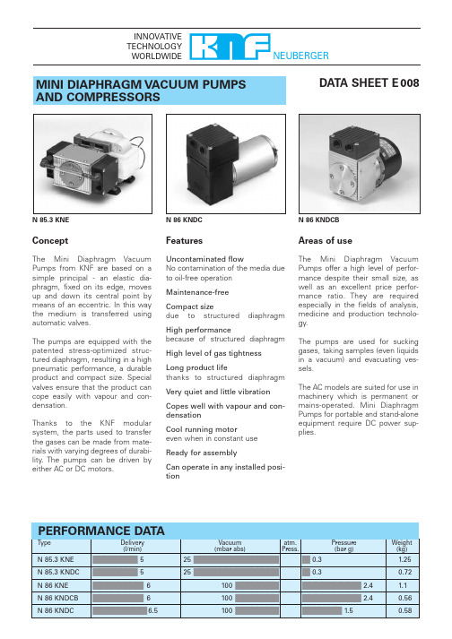
MINI DIAPHRAGM VACUUM PUMPSAND COMPRESSORSN 86 KNDCBN 86 KNDC N 85.3 KNE DATA SHEET E 008PINNOVATIVE TECHNOLOGY WORLDWIDENEUBERGER ConceptThe M ini Diaphragm Vacuum Pumps from KNF are based on a simple principal - an elastic dia-phragm, fixed on its edge, moves up and down its central point by means of an eccentric. In this way the medium is transferred using automatic valves.The pumps are equipped with the patented stress-optimized struc-tured diaphragm, resulting in a high pneumatic performance, a durable product and compact size. Special valves ensure that the product can cope easily with vapour and con-densation.Thanks to the KNF modular system, the parts used to transfer the gases can be made from mate-rials with varying degrees of durabi-lity. The pumps can be driven by either AC or DC motors.FeaturesUncontaminated flowNo contamination of the media due to oil-free operation Maintenance-freeCompact sizedue to structured diaphragm High performancebecause of structured diaphragm High level of gas tightness Long product lifethanks to structured diaphragm Very quiet and little vibration Copes well with vapour and con-densationCool running motoreven when in constant use Ready for assemblyCan operate in any installed posi-tionAreas of useThe M ini Diaphragm Vacuum Pumps offer a high level of perfor-mance despite their small size, as well as an excellent price perfor-mance ratio. They are required especially in the fields of analysis,medicine and production technolo-gy.The pumps are used for sucking gases, taking samples (even liquids in a vacuum) and evacuating ves-sels.The AC models are suited for use in machinery which is permanent or mains-operated. M ini Diaphragm Pumps for portable and stand-alone equipment require DC power sup-plies.N 85.3 KNE N 85.3 KTE4)Phillips Petroleum, registered trade mark 6)Du Pont, registered trade markN 85.3 KNDC N 85.3 KTDCP1)PDimensions 5)(mm)5)All dimensional tolerances conform to DIN ISO 2768-1, Tolerance Class VF l o w c a p a c i t y l /m i n (L i t r e a t S T P )F l o w c a p a c i t y l /m i n (L i t r e a t S T P )F l o w c a p a c i t y l /m i n (L i t r e a t S T P )F l o w c a p a c i t y l /m i n (L i t r e a t S T P )Vacuumatm. Press.Vacuumatm. Press.Vacuum atm. Press.Vacuumatm. Press.N 85.3 KNEN 85.3 KNDCN 85.3 KTEN 85.3 KTDC4924.5118430.512961404860M4300±30from motor body89104G 1/818direction of rotation10direction of rotationN 86 KNE N 86 KTEN 86 KNDCB N 86 KTDCBP VERSION WITH BRUSHLESS DC MOTOR PT o comply with CE standards (EMC guideliness to EN 55014-1),attention must be paid to the specifications in the operating instructions.F l o w c a p a c i t y l /m i n (L i t r e a t S T P )F l o w c a p a c i t y l /m i n (L i t r e a t S T P )F l o w c a p a c i t y l /m i n (L i t r e a t S T P )F l o w c a p a c i t y l /m i n (L i t r e a t S T P )Vacuumatm. Press. PressureVacuumatm. Press. PressureVacuumatm. Press. PressureN 86 KNDCBN 86 KTEN 86 KTDCBdirection of rotationN 86 KNDC N 86 KTDCP - - - - - - - for short periods onlyF l o w c a p a c i t y l /m i n(L i t r e a t S T P )F l o w c a p a c i t y l /m i n (L i t r e a t S T P )N 86 KTDCN 86 KNDCVacuumatm. Press. PressureVacuumatm. Press. Pressure300±30frommotor bodydirection of rotationM4max. 7 deepMODEL CODE FOR EASY ORDERINGThe model code is identical to the order number. It is made up as follows:In addition the motor data must be given in the purchase order (voltage, frequency,and protection class). In our extensive program you are sure to find the pump you need for your particular application.TECHNICAL DETAILSM aximum permissible gas and ambient temperature 40°C.Motors with other voltages, frequencies and protection classes on request.KNF - the competent partner for vacuum and compressor technology. Especially for unusual problems. Call us and talk to our application engineers.KNF reserves the right to make changes.R 10/2003 Printed in GermanyHints on function, installation,and service: see back sideDescription Order No.DetailsSilencer 000345Filter000346Hose connector 001936PA Hose connector 025671PVDFRubber foot024435for N 85.3/N 86__EKNF Neuberger GmbHDiaphragm Pumps + SystemsAlter Weg 3D-79112 FreiburgTel. ++49 (0)7664/5909-0Fax ++49 (0)7664/5909-99www.knf.deE-mail: info@knf.deAccessoriesN 85.3 Heads in series (2-stage)Head connectionsHINTS ON FUNCTION,INSTALLATION AND SERVICEFUNCTION OF KNF DIAPHRAGM VACUUM P UMP S AND COM-PRESSORSAn elastic diaphragm is moved up and down by an eccentric (see illustration). On the down-stroke it draws the air or gas being handled through the inlet valve. On the up-stroke the diaphragm forces the medium through the exhaust valve and out of the head. The compression chamber is hermetically separated from the drive mechanism by the diaphragm. The pumps transfer, evacuate and com-press completely oil-free. Diaphragm pump HINTS ON INSTALLATION ANDOPERATION•Range of use: Transferring air and gasesat temperatures between +5°C and+40°C•Use chemically resistant version foraggressive gases and vapours•Permissible ambient temperature:between +5°C and +40°C•The standard pumps are not suitablefor use in areas where there is a riskof explosion. In these cases there areother products in the KNF program -please ask us for details•The pumps are not designed to startagainst pressure or vacuum; when apump is switched on the pressure inthe suction and pressure lines must beatmospheric. Pumps that start againstpressure or vacuum are available onrequest•To prevent the maximum operatingpressure being exceeded, restriction orregulation of the air flow should onlybe carried out in the suction line•Components connected to the pumpmust be designed to withstand thepneumatic performance of the pump•Install the pump so that the fan candraw in sufficient cooling air•Fit the pump at the highest point in thesystem, so that condensate cannotcollect in the head of the pump - thatprolongs working-life.HINTS ON SERVICEThe diaphragm and valve plates are theonly parts of the KNF diaphragm pumpssubject to wear. They are easy to change,as no special tools are needed.If you have any questions, please call ourapplication engineers (see below forcontact telephone number).KNF Neuberger GmbHDiaphragm Pumps + SystemsAlter Weg 3D 79112 FreiburgTel. ++49 (0)7664/5909-0Fax ++49 (0)7664/5909-99www.knf.deE-mail: info@knf.de。
- 1、下载文档前请自行甄别文档内容的完整性,平台不提供额外的编辑、内容补充、找答案等附加服务。
- 2、"仅部分预览"的文档,不可在线预览部分如存在完整性等问题,可反馈申请退款(可完整预览的文档不适用该条件!)。
- 3、如文档侵犯您的权益,请联系客服反馈,我们会尽快为您处理(人工客服工作时间:9:00-18:30)。
锂离子电池的电极制造,正极浆料由粘合剂、导电剂、正极材料等组成;负极浆料则由粘合剂、石墨碳粉等组成。
正、负极浆料的制备都包括了液体与液体、液体与固体物料之间的相互混合、溶解、分散等一系列工艺过程,而且在这个过程中都伴随着温度、粘度、环境等变化。
苏州埃立特流体设备有限公司专业为客户提供高品质进口化工泵。
浆料在输送过程中所使用的包含输送泵、过滤装置、分散装置、储料罐等。
考虑到浆料输出的稳定性会对集流体涂布等环节有重要的影响,所以选择输送泵时要选择动力稳定的输送设备,通常所使用的是All-Flo隔膜泵。
All-Flo隔膜泵的特点:
1、阀芯由自润滑材料Acetal(乙缩醛)做成梭形结构,让它的机械摩擦降到最低,所以无需额外添加润滑油;
2、气阀组件数量少,备件更换费用较低;
3、无通风孔设计,且阀芯为乙缩醛材质,使其能忍受较“脏”和“湿润”的气源;
4、塑料泵的中间体均为聚丙烯材质,即使膜片破裂,也不担心输送的酸碱性物
料腐蚀中心腔体;
5、也不用担心使用环境中酸雾或碱雾的腐蚀。