基于增量式PID算法的高精度温控系统的设计
基于增量式PID算法的温室温湿度控制系统设计
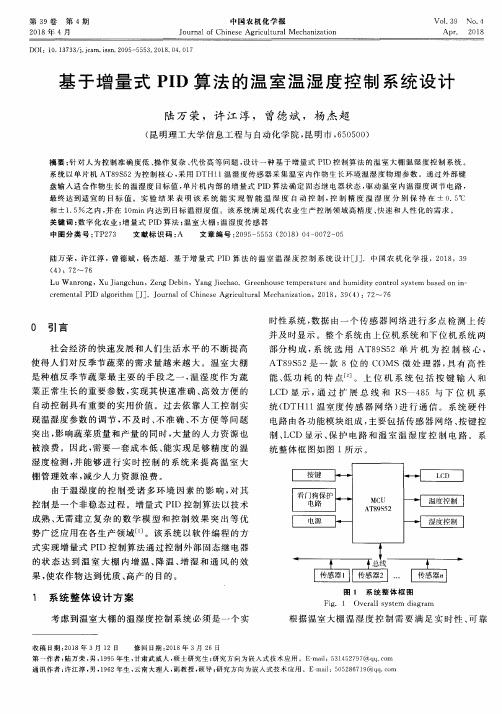
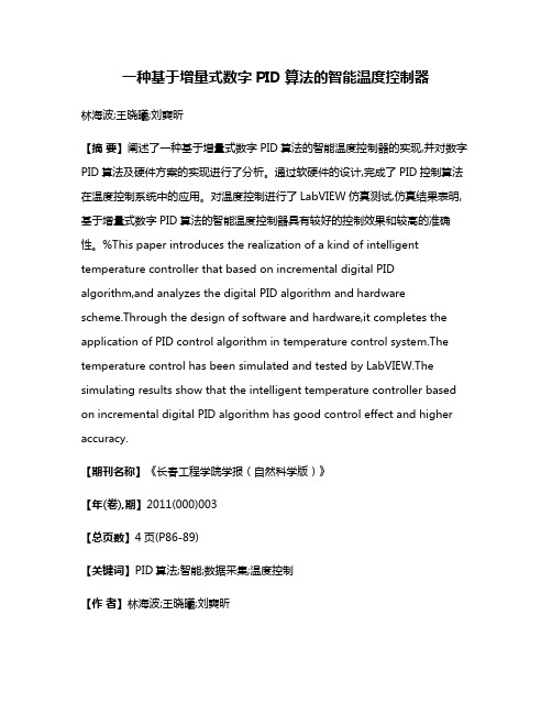
图 1 系统 整 体 框 图
Fig. 1 Overall system diagram
根据 温 室大棚 温 湿 Fra bibliotek 控制 需 要 满 足 实 时 性 、可 靠
收 稿 日期 :2018年 3月 12日 修 回 日期 :2018年 3月 26 日 第 一 作 者 :陆万 荣 ,男 ,1995年 生 ,甘肃 武 威 人 ,硕 士 研 究 生 ;研 究 方 向为 嵌 入 式 技 术 应 用 。E—mail:531452797@ qq.COII1 通 讯 作 者 :许 江 淳 ,男 ,1962年 生 ,云南 大理 人 ,副 教 授 ,硕 导 ;研究 方 向 为嵌 人 式 技 术 应 用 。E mail:5052867l9@qq.com
第 39卷 第 4期 2018年 4月
中 国 农机 化 学 报 Journal of Chinese Agricultural M echanization
V o1.39 N O.4 A pr. 2O18
基 于增 量 式 PID算 法 的温 室温 湿 度控 制 系统 设计
陆 万 荣 ,许 江 淳 , 曾德 斌 ,杨 杰 超
基于STM32和增量PID算法的温度控制系统设计说明书

5th International Conference on Advanced Materials and Computer Science (ICAMCS 2016)The constant temperature control system design based on STM32 andPID algorithmZhao Xuyang1,a and Yang Hao2,b1School of Zhao Xuyang,,China Jiliang University,Hangzhou 310000,China2School of Yang Hao,China Jiliang University,Hangzhou 310000,Chinaa ,b****************.cnKeywords: PID Algorithm;STM32;semiconductor temperature regulator;constant temperatureAbstract. Time—varying, nonlinear and multivariable coupling are characteristics of temperature. In the temperature control process, the detected temperature is often lags behind the regulation of temperature, which will cause the phenomenon such as the temperature of the controlling system overshoot and temperature oscillation. Temperature control is proposed based on incremental PID algorithm model in this paper, the system uses low-power STM32 as the main chip, DS18B20 digital temperature sensor and semiconductor temperature regulator. Experimental results show that the system can effectively maintain the temperature of the system constant.IntroductionIn natural environment, the system will generate a heat exchange which is difficult to control with the outside world, and produce unpredictable interference.During this situation it will be difficult to achieve in precise temperature controlling. When performing high-precision temperature control, temperature tends to produce overshoot phenomenon [1].Temperature control system with a lag, nonlinear and time-varying characteristics, can not establish a precise mathematical model, therefore, the use of conventional linear control theory can not achieve satisfactory control effect. semiconductor temperature controller working condition have a relationship with heat conditions and the environment factors. its work process is a non-steady state process, it needs to be addressed precisely controlled .PID control theory has a characteristic of convenient parameter setting, flexible structural change, robust and easy to implement [1,2]. the system design using incremental PID algorithm can not only solve the above problems, but also in the unsupervised, for a long time temperature will be automatically collected, automatic controlling of the semiconductor temperature controller achieves heating or cooling function, the system temperature will always be maintained constantly.Using a master chip STM32 and digital temperature sensor DS18B20 design a constant temperature system, the advantages consist of anti-interference digital signal, high sensitivity, fast response, and reasonable controlling of semiconductor temperature regulator,through the whole system design can effectively realize a special case temperature stable. within the setting temperature model of a small area in the design of a system with the column a special case. the result shows that the temperature controlling system of constant small area with very good results after analysis.System hardware designHardware System features modular designDS18B20 digital temperature sensor is placed on both sides of a special case, the datas are directly send to the master chip STM32 so that microchip could obtain temperature value, According to the requirements of the system setting temperature judgment mainly adopts the cooling method in the operation of the semiconductor temperature regulator in regulating or adjust temperature with heating methods . adjusting the way through the PID control algorithm of thetemperature read by the line processing, while the master semiconductor chip STM32 control thermostat-off, so that a special case temperature maintained at a stetted temperature. this system without manual monitoring, and data can be collected via the RS232 serial port and then the observed system temperature curve plotted, by autonomous control system effectively maintained aThe hardware system module functional designSystem functional hardware modules include temperature acquisition module, data display and export module, fan power switch module, semiconductor temperature controller module five modules.Temperature acquisition moduleTemperature acquisition module uses a digital temperature sensor DS18B20, the sensor has high measurement accuracy, the output signal is digital with anti-jamming performance, no front-end data processing module, direct access to the STM32's I / O port , the master chip can directly read data.Data display and export moduleTaking the versatility of the system into account, used in the design is one of the communication interfaces RS232 computer data communication channel, data communication is actually using a USB data format. In this communication stepper can get higher data transfer speeds, true plug and play, it can also make it easy to connect the communication between different devices.When data is displayed using USB to serial cable to the PC, using serial debugging assistant can easily read the temperature data acquisition, and also can import the data into a computer terminal for data storage. Therefore, the use of a standard interface technology can effectively solve the problem of inconsistent communication protocols [4].Fan power switch moduleWhen the semiconductor thermostat is in the cooling operation state, it is important to timely dissipate the heat, otherwise it will make semiconductor refrigeration unnormal. According to the determination of the fan work condition, by the cathode of high and low level control fan switch, the anode is normal power supply connection.This module is controlled by the master chip I / O port output level to control the fan switch purposes.Semiconductor temperature regulator moduleThe core of the temperature control system is semiconductor temperature regulator. The semiconductor temperature regulator reliability is relatively high, while the power supply terminal through the access of different polarity power supply, it can absorb heat and release heat so as to achieve the effect of refrigeration and heating. using this module is characterized by the use of a device can replace separate heating and cooling systems. precise temperature control thermostat semiconductor characteristics to facilitate the composition of automated control systems [1,2]. Figure 2 is a semiconductor temperature control circuit diagram of a switching regulator.Figure 2 Diagram of semiconductor thermostat switch control circuitSoftware system and algorithm designThe system software design process includes temperature digital signal acquisition, temperature display、PID algorithm temperature control 、temperature feedback components. The main part of the PID control algorithm is changing the value of the ambient temperature and after the feedback the temperature regulation value, it ultimately achieve the effect of Steady-State accuracy.PID algorithm designPID algorithm has a simple structure, the robust performance is good, high reliability, easy parameter setting features .P, I, D control law have their own separate areas, performing linear combination constitutes control amount, then the control amount will control objects [5,6].In the control system, a system based on real-time temperature and the set threshold value increment controls semiconductor temperature regulator operation. Therefore, the output portion of the controller is required to control the amount of incremental, in the design of the system is used incremental PID algorithm [7,8]. equation for the incremental PID algorithm is as follows.△u = A • e (k) + B •e (k-1) + C • e (k-2) (1) Where: △u increment control quantity; ratio of A, B, C as PID control, differentiation, integration coefficients; e (k), e (k-1), e (k-2) before and after the three measurements the temperature difference .Precision of the digital temperature sensor DS18B20 can reach ± 0.5 ℃, when setting the thermostat system temperature threshold, typically the change of temperature thermostat system is set within ± 0.5 ℃, partly because the system itself and the temperature sensor error performance limits; on the other hand with a time-varying temperature, constant temperature control need to constantly switch control semiconductor thermostat and fan control to a large extent, this will reduce the life of the instrument, and even burn the instrument.The main process of PID algorithm controller is parameter tuning, tuning in essence is through changing the regulator parameters to match the characteristics of properties and processes in order to improve the dynamic and static index system, so as to achieve the best control effect parameters. in tuning process, the first controller is as a pure proportional controller, form a closed loop, changing the coefficients, so that the coefficient corresponding to the input reaches a critical state (oscillation amplitude). Last in turn introduced differential and integral parameters according to attenuation 1 / 4 obtained, this attenuation can take into account the stability and rapidity.The result of the experiment and analysisReal entire test system shown in Figure 3, including the serial communication section, column oven, control panel and temperature control systems DS18B20, fans, and other semiconductor temperature regulator.Figure 3 System schematic diagramFirst obtaining room temperature, setting the thermostat system defined temperature less than room temperature, then connecting to the PC serial display interface, running the system, it will be observed that the fan is running, the positive power semiconductor thermostat is in cooling state, when the temperature is close to the serial display system the lower limit set temperature, the fan and the temperature of the semiconductor regulators are turned off, followed by heat exchange with the outside of the system will cause the temperature to rise, when the temperature rises to the set temperature limit, the fan is turning and positive power semiconductor in the temperature regulator cooling state, repeating the cooling state maintains the temperature at the set range. Column Compartment closed box is a small area, gathering room temperature is 25.4 ℃, the set temperature for the system is 20 ℃, when the permissible error set upper and lower threshold values were 20.5 ℃ and 19.5 ℃, the temperature control results shown in Figure 4Figure 4 Diagram of temperature controlling effectThe collected data of constant temperature system threshold below room temperature is as table 1. Table 1 Thermostatic system threshold below room temperature data collection formTime Left of box Middle of box Right of box0min 25.2℃ 25.4℃ 25.4℃5min 21.3℃ 20.6℃ 20.9℃10min 19.8℃ 20.1℃ 19.6℃ 20.3℃ 19.8℃ 20.1℃column oven PowersupplyDS18B20theoretical temperature, the blue curve represents the set temperature threshold. The data of Table 1 is collected at the different parts of the column oven temperature on a fixed time interval ,by this set of data can provide data support for the precise control of various parts of the column oven . variation tendency from the red curve show the actual temperature drop is divided into stages and temperature stabilization phase, after 225 seconds the system enter into the temperature stabilization phase. under the control of the incremental PID algorithm, the value of a small area of the temperature and the temperature of the theory has a good agreement, because of the exchange principle of the temperature of the nature result that the actual temperature are some errors in the data, but in the end the system could be stabilized, error is within a controllable range .by the ratio of the critical ratio method tuning PID proportion P, the integral I, differential D parameters, ideal set of data is debugged within surplus overshoot, it will be saw that the overshoot of the actual temperature curve is reduced to 17.5 % .this control process reduces the overshoot and maintain a constant temperature system efficiently and quickly.SummarySmall regional integrated climate control system is made up of a dual data collection, synchronous dual refrigeration heating control systems and incremental PID control algorithm. The algorithm combined with semiconductor temperature controller provides a set of high-precision temperature control system. solutions can effectively reduce outside interference, maintaining the temperature of the entire area of constant temperature changes in real-time monitoring system. this system temperature control effect is obvious, the structure has small size, and is suitable for most stringent temperature requirements systems, as well as the instrument cooling system, can effectively improve the instrument of practical life.AcknowledgmentsThanks to the teacher's guidance and let me join the related projects include science and technology plan projects in Zhejiang province (2015C33009), science and technology plan projects in Jiaxing (2015 AY11008)References[1] Wang Hongjie,Du Jialian,Chen Jincan,Optimization on the Performa-nce Characteristics of a Semiconductor Refrigeration System, J. R-efrigeration,1999,18(4):54-58.[2]Fan Hanbai,Xie hanhua,Semiconductor Refrigerator Temperature Con-trol System with High-precision Based on Thyristor Phase-shifted Control, J. Instrument Technique and Sensor,2012,5:103-105.[3] Cai Jinping,Li Li,The Small Area Temperature Control Model Based on Improved PID Algorithm Simulat, J. Computer Simulation,2015,32(6) :237-240.[4] Ge Leijiao,Mao Yizhi,Li Qi et al,RS232 Serial Interface Communic-ation with the C Language, J. Journal of Hebei University of Tech-nology,2008,37(6):11-16.[5] Xiao Wenjian,Li yongke,Design of Intelligent Vehicle Based on In-cremental PID Control Algorithm, J. Information technology,2012, 10:125-127.[6] Yan Xiaozhao,Zhang Xingguo,Application of Increasing PID Contro-lling Method in Temperature Controlling System, J. Journal of Nan-tong University,2006,5(4):48-51.[7] Wang Shuyan,Shi Yu,Feng Zhongxu et al ,A Method for Controlling a Loading System Based on a Fuzzy PID Controller, J. Mechanical S-cience and Technology for Aerospace Engineering,2011,30(1):166-169.[8] LI Fengman.,The Research of Controlling Arithmetic for Figure PID, J. Journal of Liaoning University,2005,32(4):367-370.。
基于PID电加热炉温度控制系统设计(1)汇总

基于PID 电加热炉温度控制系统设计摘要 电加热炉随着科学技术的发展和工业生产水平的提高,已经在冶金、化工、机械等各类工业控制中得到了广泛应用,并且在国民经济中占有举足轻重的地位。
对于这样一个具有非线性、大滞后、大惯性、时变性、升温单向性等特点的控制对象,很难用数学方法建立精确的数学模型,因此用传统的控制理论和方法很难达到好的控制效果。
单片机以其高可靠性、高性能价格比、控制方便简单和灵活性大等优点,在工业控制系统、智能化仪器仪表等诸多领域得到广泛应用。
采用单片机进行炉温控制,可以提高控制质量和自动化水平。
一、 绪论在本控制对象电阻加热炉功率为8可W ,由220V 交流电供电,采用双向可控硅进行控制。
本设计针对一个温度区进行温度控制,要求控制温度范围50~350C ,保温阶段温度控制精度为正负1度。
选择合适的传感器,计算机输出信号经转换后通过双向可控硅控制器控制加热电阻两端的电压。
其对象问温控数学模型为: 1)(+=-s T e K s G d sd τ 其中:时间常数Td=350秒,放大系数Kd=50,滞后时间τ=10秒, 控制算法选用改PID 控制图1.1系统总体结构图二、控制系统的建模和数字控制器设计图2 PID算法流程图数字PID控制算法PID控制器是通过计算机PID控制算法程序实现的。
计算机直接数字控制系统大多数是采样-数据控制系统。
进入计算机的连续-时间信号,必须经过采样和整量化后,变成数字量,方能进入计算机的存贮器和寄存器,而在数字计算机中的计算和处理,不论是积分还是微分,只能用数值计算去逼近。
图2.1位置PID控制算法简化示意图在数字计算机中,PID 控制规律的实现,也必须用数值逼近的方法。
当采样周期相当短时,用求和代替积分,用差商代替微商,使PID 算法离散化,将描述连续时间PID 算法的微分方程,变为描述离散-时间PID 算法的差分方程。
∑⎰==k j i s j e T T d e T 0t 0)()(1ττ用矩形积分时,有 )]1()([)(--=k e k e T T dt t de T S D d (1) 用差分代替微分 00))]1()([)(()([)(u k e k e T T j e T T k e K k u S D k j i sp +--+++=∑= (2) 由上式得01)]1()([)()()(u u k e k e K k e K k e K k D k j p +--++=∑= (3)式中 u 0——控制量的基值,即k=0时的控制;u(k)——第k 个采样时刻的控制;K P ——比例放大系数;K I ——积分放大系数;I S P I T T K K = S D P D T T K K =K D ——微分放大系数;T S ——采样周期。
温度控制的增量式pid算法

温度控制的增量式pid算法温度控制是工业生产中非常重要的一项技术,它可以保证生产过程中的温度稳定,从而保证产品的质量。
而PID算法是一种常用的控制算法,它可以根据当前的误差来调整控制器的输出,从而实现对温度的精确控制。
在本文中,我们将介绍一种基于增量式PID算法的温度控制方法。
增量式PID算法是一种常用的控制算法,它可以根据当前的误差和误差变化率来计算控制器的输出。
具体来说,增量式PID算法可以分为三个部分:比例控制、积分控制和微分控制。
比例控制是根据当前误差来计算控制器的输出,积分控制是根据误差的积分来计算控制器的输出,微分控制是根据误差的变化率来计算控制器的输出。
这三个部分的输出可以相加得到最终的控制器输出。
在温度控制中,我们可以将温度传感器的输出作为反馈信号,将设定温度作为目标信号,然后使用增量式PID算法来计算控制器的输出。
具体来说,我们可以将当前温度与设定温度的差值作为误差,将当前温度与上一次温度的差值作为误差变化率,然后使用增量式PID算法来计算控制器的输出。
控制器的输出可以通过控制加热器或冷却器的功率来实现对温度的控制。
需要注意的是,增量式PID算法需要对控制器的输出进行积分和微分,这可能会导致控制器的输出出现过冲或震荡的情况。
为了避免这种情况的发生,我们可以使用一些技巧来优化控制器的输出。
例如,我们可以使用限幅器来限制控制器的输出范围,或者使用滤波器来平滑控制器的输出。
增量式PID算法是一种非常有效的温度控制方法,它可以根据当前的误差和误差变化率来计算控制器的输出,从而实现对温度的精确控制。
在实际应用中,我们需要根据具体的情况来选择合适的控制参数,并使用一些技巧来优化控制器的输出,从而实现更加稳定和精确的温度控制。
基于增量型PID控制的烘箱自动控温系统
基于增量型PID控制的烘箱自动控温系统作者:杜中白志刚来源:《电脑知识与技术·学术交流》2008年第26期摘要:应变片粘结剂的固化、光弹试件的浇铸和固化等过程都需要电阻丝加热型烘箱严格按照给定的升温、保温和降温(不低于室温)折线进行精确的升温、保温和降温过程。
烘箱自动控温系统根据PID调节的自动控制原理,并考虑到被控对象大惯性、大迟延的特点,采用Smith补偿提高系统的自动控制品质,实现了烘箱温度自动测控。
运行结果表明,烘箱自动控温系统可靠性强,精度高,完全满足生产要求。
关键词:烘箱;自动控温;PID;Smith补偿中图分类号:TP273文献标识码:A 文章编号:1009-3044(2008)26-1651-03An Oven Temperature Autocontrol System Based on Incriment PID ControlDU Zhong1 , BAI Zhi-gang2(1.School of Computer Science and Technology, Southwest University of Science and Technology,Mianyang 621010, China; 2.The Air Force Military Representative Office Resident in Chengdu Region,Chengdu 610041, China )Abstract:These occasions need resistance wire heating oven to accurately control temperature according to the polyline which includes process of warm heating,holding and descenting, so long as the temperature not less than room temperature, which include solidfying of agglomerant on strain gage, casting of optics elastomeric test pieces or solidfying,etc. The oven temperature autocontrol system was based on PID adjustment control theory.considering the large object inertia and characteristics of delay, Smith compensation has been used for this system to increase the autocontrol quality. The runing results show that this system can fully meet the work requirements with high reliability and high precision.Key words: oven; temperature autocontrol; PID; Smith compensation1 前言应变片粘贴后粘贴剂的固化、光弹试件的浇铸和固化等过程都需要电阻丝加热型烘箱严格按照给定的升温、保温和降温(不低于室温)折线进行升温、保温和降温过程。
基于PID自动控制的高精度温控电路设计与实现
电子技术与软件工程Electronic Technology & Software Engineering电子技术Electronic Technology基于PID 自动控制的高精度温控电路设计与实现郑本昌(中国运载火箭技术研究院研究发展部 北京市100076 )摘 要;本文为实现某半导体激光器对温度控制的需求,提出了一种基于PID 自动控制原理的高精度温控电路设计与实现方法。
采用 采用齐格勒一尼柯尔斯整定规则对PID 电路参数进行设定,有机结合模拟电路与数字电路优点,实现了对微波腔的大范围,快速响应和高稳定性的温度控制。
测试结果表明,温控精度达到±0.01°以内。
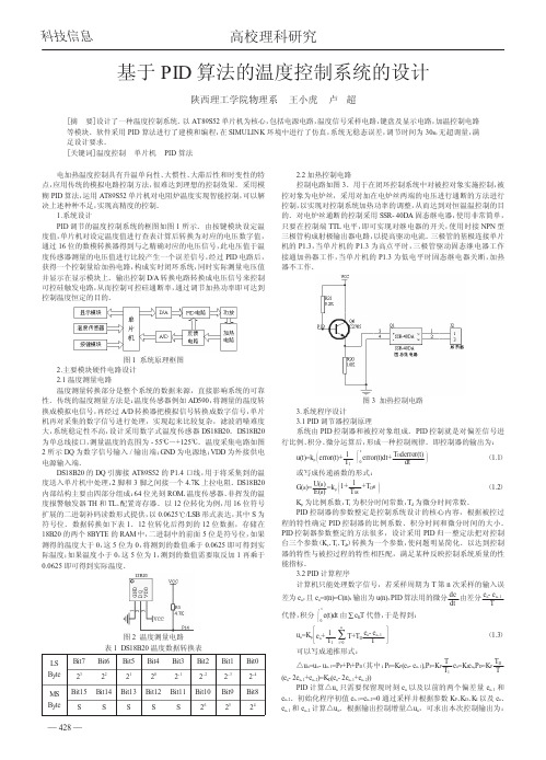
关键词:温控电路;PID 控制;高精度1引言半导体激光器由于其体积小、效率高、寿命长等优点,在激光光通讯、光存储、激光高速印刷、光信息处理、光传感等诸多方面 得到广泛而至关重要的应用(,-3|o 但从物理机制上讲,温度变化影 响了半导体激光器的这一美妙应用,由于激活介质的能带中等效费米能级随温度变化,使得增益曲线漂移从而造成频率漂移,甚至导致跳模,另外,温度变化引起激光器腔长变化,也将导致频率变化(4'5,o 由此可见,控制温度使其稳定是一项重要而且必不可少的任务。
针对半导体激光器控温,国内外进行了大量的研究。
PID(Proportional Integral Derivative)控制作为揑制工程中技术成熟,应 用广泛的一种控制策略,能够在一定程度上合理的解决动态稳定性和静态增益之间的矛盾,因此吸引了众多研究人员的兴趣。
贺春贵⑹等人分析了 PI 参数对温度控制稳定性的影响及温度控制的短期稳 定性,卢燕⑺等采用DSP 数字信号处理芯片的方式实现了 ±0.1。
控 温精度的温控系统,鲍健181等人实现了 ±0.05。
的高精度二极管激光 温度控制器。
本文针对某激光器控温精度±0.1。
基于PID算法的温度控制系统设计

基于PID算法的温度控制系统设计随着科技的不断发展,温度控制系统得到了广泛的应用。
无论是工业制造还是家庭生活,都会用到温度控制系统。
在这个系统中,PID算法是最常用的控制算法之一。
本文将介绍基于PID算法的温度控制系统的设计。
一、系统概述温度控制系统可以用于控制温度控制在一定范围内。
该系统包括一个温度传感器、一个控制器、一个执行器和一个热源。
其中,温度传感器用于将温度信号转换成电信号,控制器用于处理电信号,执行器用于控制热源加热或停止加热。
在温度控制系统中,PID算法是控制器中使用的一种算法。
二、PID算法原理PID控制算法分别根据偏差、积分错误和微分错误来控制系统。
PID算法控制器包括控制模块、时间模块、输出模块、PID模块和作用模块。
该算法可以通过增大或减少控制器的输出来控制系统的状态,以便实现温度控制。
模型中包含比例项、积分项和微分项。
控制器采用增益因子对其中的每一个部分进行调整,以便更好地控制系统。
三、系统设计在设计基于PID算法的温度控制系统时,需要首先将传感器连接到控制器。
控制器可以收集从温度传感器中收集的温度信号并将其转换成电信号。
然后,该信号将被发送到PID算法控制器,该控制器可以使用PID算法来计算输出信号。
输出信号可以通过执行器来控制加热或停止加热的热源,从而实现温度控制。
四、系统的优点基于PID算法的温度控制系统可以实现更准确和更稳定的温度控制。
相对于其他控制算法来说,该算法具有更优秀的响应特性和更敏感的响应速度。
此外,该算法可以进行现场校准,更容易进行二次开发。
五、系统的应用基于PID算法的温度控制系统广泛应用于各个领域。
在工业制造领域,该系统可以用于控制各种设备和工具的温度,以保证生产质量。
在医疗领域,该系统可以用于监控体温,并确保患者在治疗过程中保持稳定的体温。
此外,在家庭生活中,基于PID算法的温度控制系统可以帮助人们更好地控制室内温度,从而提高生活舒适度。
总之,基于PID算法的温度控制系统可以广泛应用于各种领域。
基于PID法温度控制

基于P I D法温度控制 Document number【AA80KGB-AA98YT-AAT8CB-2A6UT-A18GG】于400℃,发热棒、发热圈还将会对被加热的器件进行加热,即使温度控制器发出信号停止加热,被加热器件的温度还往往继续上升几度,然后才开始下降。
当下降到设定温度的下限时,温度控制器又开始发出加热的信号,开始加热,但发热丝要把温度传递到被加热器件需要一定的时候,这就要视乎发热丝与被加热器件之间的介质情况而定。
通常开始重新加热时,温度继续下降几度。
所以,传统的定点开关控制温度会有正负误差几度的现象,但这不是温度控制器本身的问题,而是整个热系统的结构性问题,使温度控制器控温产生一种惯性温度误差。
2、PID控制解决要解决温度控制器这个问题,采用PID控制技术,是明智的选择。
PID控制,是针对以上的情况而制定的、新的温度控制方案,用先进的数码技术通过Pvar、Ivar、Dvar三方面的结合调整,形成一个模糊控制,来解决惯性温度误差问题。
然而,在很多情况下,由于传统的温度控制器温控方式存在较大的惯性温度误差,往往在要求精确的温控时,很多人会放弃自动控制而采用调压器来代替温度控制器。
但是用调压器来代替温度控制器时,必须在很大程度上靠人力调节,随着工作环境的变化而用人手调好所需温度的度数,然后靠相对稳定的电压来通电加热,勉强运作,但这决不是自动控温。
当需要控温的关键很多时,就会手忙脚乱。
这样,调压器就派不上用场,因为靠人手不能同时调节那么多需要温控的关键,只有采用PID 模糊控制技术,才能解决这个问题,使操作得心应手,运行畅顺。
二、该温控系统的结构和原理:1、系统的结构:系统功能主要实现断水保护和高水位指示、自动保温、自动报警及高温保护功能。
用双排数码管分别显示设计与测量温度,保温时间,加热周期及PID 的各参数,当测量温度达保温温度时,数码管显示设定温度。
当达设定温度时,数码管应该切换到设定的保温时间,并倒计时。
基于PID算法的温度控制系统的设计
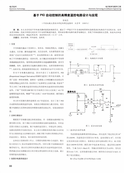
2.2 加热控制电路 控制电路如图 3。用于在闭环控制系统中对被控对象实施控制,被 控对象为电炉丝,采用对加在电炉丝两端的电压进行通断的方法进行 控制,以实现对控制系统加热功率的调整,从而达到对恒温温控制的目 的。对电炉丝通断的控制采用 SSR- 40DA 固态继电器,使用非常简单, 只要在控制端 TTL 电平,即可实现对继电器的开关,使用时接 NPN 型 三极管构成射极输出器电路,以提高驱动电流。三极管的基极连接单片 机的 P1.3,当单片机的 P1.3 为高点平时,三极管驱动固态继电器工作 接通加热器工作,当单片机的 P1.3 为低电平时固态继电器关断,加热 器不工作。
图 1 系统原理框图 2.主要模块硬件电路设计 2.1 温度测量电路 温度测量转换部分是整个系统的数据来源,直接影响系统的可靠 性。传统的温度测量方法是:温度传感器例如 AD590,将测量的温度转 换成模拟电信号,再经过 A/D 转换器把模拟信号转换成数字信号,单片 机再对采集的数字信号进行处理,实现起来比较复杂,滤波消噪难度 大,系统稳定性不高,设计采用数字式温度传感器 DS18B20。DS18B20 为单总线接口,测量温度的范围为 - 55℃~+125℃。温度采集电路如图 2 所示 DQ 为数字信号输入 / 输出端;GND 为电源地;VDD 为外接供电 电源输入端。 DS18B20 的 DQ 引脚接 AT89S52 的 P1.4 口线,用于将采集到的温 度送入单片机中处理,2 脚和 3 脚之间接一个 4.7K 上拉电阻。DS18B20 内部结构主要由四部分组成:64 位光刻 ROM、温度传感器、非挥发的温 度报警触发器 TH 和 TL、配置寄存器。以 12 位转化为例,用 16 位符号 扩展的二进制补码读数形式提供,以 0.0625℃/LSB 形式表达,其中 S 为 符号位。数据转换如下表 1。12 位转化后得到的 12 位数据,存储在 18B20 的两个 8BYTE 的 RAM 中,二进制中的前面 5 位是符号位,如果 测得的温度大于 0,这 5 位为 0,将测到的数值乘于 0.0625 即可得到实 际温度;如果温度小于 0,这 5 位为 1,测到的数值需要取反加 1 再乘于 0.0625 即可得到实际温度。
一种基于增量式数字PID算法的智能温度控制器
一种基于增量式数字PID算法的智能温度控制器林海波;王晓曦;刘奭昕【摘要】阐述了一种基于增量式数字PID算法的智能温度控制器的实现,并对数字PID算法及硬件方案的实现进行了分析。
通过软硬件的设计,完成了PID控制算法在温度控制系统中的应用。
对温度控制进行了LabVIEW仿真测试,仿真结果表明,基于增量式数字PID算法的智能温度控制器具有较好的控制效果和较高的准确性。
%This paper introduces the realization of a kind of intelligent temperature controller that based on incremental digital PID algorithm,and analyzes the digital PID algorithm and hardware scheme.Through the design of software and hardware,it completes the application of PID control algorithm in temperature control system.The temperature control has been simulated and tested by LabVIEW.The simulating results show that the intelligent temperature controller based on incremental digital PID algorithm has good control effect and higher accuracy.【期刊名称】《长春工程学院学报(自然科学版)》【年(卷),期】2011(000)003【总页数】4页(P86-89)【关键词】PID算法;智能;数据采集;温度控制【作者】林海波;王晓曦;刘奭昕【作者单位】长春工程学院电气与信息工程学院,长春130012;大连理工大学电子信息与电气工程学部,大连116023;大连理工大学电子信息与电气工程学部,大连116023【正文语种】中文【中图分类】TP273.50 引言温度的检测和控制在理论上发展比较成熟,但在实际测量和控制中,如何保证快速实时地对温度进行采样,确保数据的正确传输,并能对所测温度场进行较精确的控制,仍然是目前需要解决的问题。
基于增量式PID控制的空气热源泵供水机温度控制系统设计
u(k) = u(k - 1) + Kp{e(k) - e(k - 1) + T +
Tie(k)
(5)
TD [e(k) - 2e(k - 1) + e(k - 2)]}
T
式(5)中 u(k)为采样 k 时刻的系统输出量,只需要
用到采样 k-2,k-1,k 这三个时刻偏差,以及向前递
保温水箱
出水温度 T1
market,mostly using electric heating and fossil energy heating. However,due to the single structure and the lack of temperature
control,energy is generated. Waste and unstable water temperature problems. In order to improve the energy utilization rate and sta⁃
4.3
图5
PID 温度控制系统结构图
温度控制方法
j=0
开始
(3)
u(k)为系统的输出量;T 为为系统的采样周期,Tit=
T/Ti,TDt=TD/T;k 为采样的序号;e(k)为系统采样 k 时
系统初始化
刻的偏差值,e(k-1)为 k-1 时刻系统的偏差值[10]。
查询温度
尽管传统 PID 算法具有以上所述的多种优势,
在实际使用中由于系统的每一次输出值都需要大
等待
量的内存配置配合运算,导致系统计算时间过长不
利于系统的实时控制[11]。针对这些问题的存在,增
量式 PID 算法相比较传统式 PID 算法有了很大的
基于PID算法的水温控制系统设计报告
基于PID的水温控制系统设计摘要本次设计采用proteus仿真软件,以AT89C51单片机做为主控单元,运用PID控制算法,仿真实现了一个恒温控制系统。
设计中使用温度传感器DS18B20采集实时温度,不需要复杂的信号调理电路和A/D转换电路,能直接与单片机完成数据的采集和处理,使用PID算法控制加热炉仿真模型进行温度控制,总体实现了一个恒温控制仿真系统。
系统设计中包含硬件设计和软件设计两部分,硬件设计包含显示模块、按键模块、温度采集模块、温度加热模块。
软件设计的部分,采用分层模块化设计,主要有:键盘扫描、按键处理程序、液晶显示程序、继电器控制程序、温度信号处理程序。
另外以AT89C51 单片机为控制核心,利用PID 控制算法提高了水温的控制精度,使用PID 控制算法实施自动控制系统,具有控制参数精度高、反映速度快和稳定性好的特点。
关键词:proteus仿真,PID,AT89C51,DS18B20温度控制目录1 系统总体设计方案论证 (1)1.1 设计要求 (1)1.2 总体设计方案 (2)2 系统的硬件设计 (3)2.1 系统硬件构成概述 (3)2.2 各单元总体说明 (4)2.3 按键单元 (5)2.4 LCD液晶显示单元 (6)2.5 温度测试单元 (7)2.6 温度控制器件单元 (8)3 恒温控制算法研究(PID)............................................................................. 错误!未定义书签。
3.1 PID控制器的设计 (10)3.2 PID算法的流程实现方法与具体程序 (12)4 系统的软件设计 (17)4.1 统软件设计概述 (17)4.2 系统软件程序流程及程序流程图 (18)4.3 温度数据显示模块分析 (19)4.4 测试分析 (22)5 模拟仿真结果 ...................................................................................................... 错误!未定义书签。
基于PID算法的PCR仪温度控制系统设计方案
基于PID算法的炉温控制系统的设计与实现
工业技术88 2015年53期基于PID算法的炉温控制系统的设计与实现王江涛身份证:3213211989****5495摘要:随着社会的发展,在生活和工业中已经广泛的使用温度控制,而现代化炉温控制已经开始自动化PID控制时代了。
控制炉温恒定是满足生产、提高效率和节能减耗的关键技术,其具有很多优势,能够进一步提高控制精度,同时使得加热时间大大降低,不短提高能源的利用,因此也是越来越受到重视。
为了更好的确保加热炉的安全运行,因此加强炉温控制系统的设计与实现的研究非常有必要。
基于此本文分析了基于PID算法的炉温控制系统的设计与实现。
关键词:PID算法;炉温控制系统;设计;实现中图分类号:TP273 文献标识码:A 文章编号:1671-5810(2015)53-0088-021 概述1.1 PID算法比例积分微分的一个简称——PID控制器,在很多工业控制应用中,控制效果良好,精度高,易于控制,不仅具有较强的适应性和鲁棒性也很好。
PID控制器一般形式的公式为:实际过程控制中可将PID的数学模型写作:比较两式可知Ki=KP/Ti,Kd=KPTd,经过拉普拉斯变换可得出一个式子:Gc(S)=Kp(1+1/TiS+TdS),这是针对PID的一个传递函数,其中各个字母代表的意义是:Kp-比例系数;Ti-积分时间常数;Td-微分时间常数;Ki和Kd 分别为积分系数和微分系数。
PID通过控制信号控制被控目标的数学原理主要也是依赖对这几个系数的运算,控制信号也是经过加权得出的,加权的对象就是系统的误差信号和相应的积分与微分量。
1.2 炉温控制原理随着自动控制理论与传感技术的发展,炉温控制实现了自动化。
采用代替手动控制中人工观察、比较、分析处理的变送器、比较器、控制器和执行器的自动控制系统如图1所示。
热电偶因冷热端温差而产生的输出电压经变送器转换为温度值;比较器用于计算目标温度和测量温度的差值,用偏差值信号通过控制器来控制执行器,调节加热电压使温度偏差趋于零,从而使炉温稳定于目标温度上。
基于PID的STM32恒温控制系统设计
成绩评定基于PID的STM32恒温控制系统设计摘要研究基于STM32单片机和温湿度传感器的恒温智能控制系统。
温度具有时变性、非线性和多变量耦合的特点。
在温度控制过程中,温度的检测往往滞后于温度的调控,从而会引起温度控制系统的温度出现超调、温度振荡的现象。
在设计中提出了基于增量式PID算法控制温度的模型,系统采用低功耗的STM32作为主控芯片、DHT11数字式温度传感器和半导体温度调节器。
实验结果表明,该系统能够有效地维持系统地恒温状态。
通过将数字PID算法和STM32单片机结合使用,整个控制系统的溫度控制精度也提高了,不仅仅满足了对温度控制的要求,而且还可以应用到对其他变量的控制过程中。
所以,在该温度控制系统的设计中,运用单片机STM32进行数字PID运算能充分发挥软件系统的灵活性,具有控制方便、简单和灵活性大等优点。
关键词:STM32,PID算法,恒温控制,DHT111绪论温度控制系统具有滞后性,时变性和非线性的特点。
无法建立精准的数学模型,因此使用常规的线性控制理论无法达到满意的控制效果。
在嵌入式温度控制系统中的关键是温度的测量、温度的控制和温度的保持,温度是工业控制对象中主要的被控参数之一。
因此,嵌入式要对温度的测量则是对温度进行有效及准确的测量,并且能够在工业生产中得广泛的应用,尤其在机械制造、电力工程化工生产、冶金工业等重要工业领域中,担负着重要的测量任务。
在日常工作和生活中,也被广泛应用于空调器、电加热器等各种室温测量及工业设备的温度测量。
但温度是一个模拟量,需要采用适当的技术和元件,将模拟的温度量转化为数字量,才生使用计算机进行相应的处理。
2 设计方案为了对于交流负载做到温度精确,升温采用控制双向可控硅导通角度进行升温控制.降温采用PWM电压控制,因为当前降温采用制冷片,风扇等降温手段,采用直流电压供电方式,选用PWM控制使降温更加精确。
温度采集选用温度传感器DHT11,好处为可做到高精度,整体框图如图1所示。
温度控制的增量式pid算法

温度控制的增量式pid算法温度控制是工业生产、生活中常用的一种控制方式,尤其在化工、食品加工等过程中,准确控制温度可以大大提高产品质量和生产效率。
因此,温度控制算法也成为了工程师们研究的重点之一。
其中,增量式PID算法被广泛应用于温度控制中。
增量式PID算法是基于传统PID算法的一种改进版本。
它可以不需要保存过去的控制误差和操作量信息,而是通过计算当前的误差与前一时刻的误差之差,即增量,来得到下一时刻的控制操作量。
相比传统的PID算法,增量式PID算法能够更快速地响应过程变化,同时也可以避免误差积分导致的系统不稳定的问题。
下面,我们将分步骤来阐述增量式PID算法在温度控制中的应用过程:第一步:采集温度信号并进行滤波在温度控制系统中,必须首先采集用于控制的温度信号,并对其进行滤波处理,以保证控制过程的准确性。
常用的滤波方式有标准差滤波法、中值滤波法、卡尔曼滤波法等。
第二步:计算增量增量式PID算法的核心在于计算当前的控制增量。
在采集、滤波之后,我们可以通过计算当前时刻的误差与前一时刻的误差之差,即上一时刻的增量,来计算当前时刻的增量。
具体公式为:△u(k) = Kc*[e(k) - e(k-1) + Td/Ti*e(k)]其中,Kc为控制器增益,e为当前时刻的误差,Td和Ti分别为微分时间常数和积分时间常数。
第三步:计算控制信号计算出当前时刻的增量后,我们可以将其加上前一时刻的控制信号,即可得到当前时刻的控制信号。
具体公式为:u(k) = u(k-1) + △u(k)其中,u(k-1)为上一时刻的控制信号。
第四步:输出控制信号最后一步是输出控制信号,将其传入温度控制器并作用于温度调节装置,以达到控制温度的目的。
总结起来,增量式PID算法在温度控制中的应用过程主要包括采集温度信号并进行滤波、计算增量、计算控制信号和输出控制信号四个步骤。
相比传统的PID算法,增量式PID算法更快速、更稳定,可以更准确地控制温度,提高生产效率和产品质量。
基于PID算法温度控制系统设计

基于PID算法温度控制系统设计作者:杨伟浩来源:《数字技术与应用》2019年第05期摘要:本文采用NTC热敏电阻温度采集,STC15F2K60S2单片机为主控芯片,以PID为核心算法、PWM控制方式控制半导体制冷片,实现恒温的温度控制系统。
硬件主要分为电源压降电路、温度采集电路、温控电路等三大部分。
关键词:PID算法;PWM;温度控制中图分类号:TP273 文献标识码:A 文章编号:1007-9416(2019)05-0016-020 绪论目前PID控制的理论研究和工程实践非常广泛,有三种比较常见的PID控制算法,分别是:位置式算法、增量式算法和积分分离算法。
本设计采用积分分离算法,要求温度可以设置在15℃到80℃之间,控制精度±0.5℃。
1 系统的硬件架构设计1.1 电源压降电路本系统电源电路采用TI公司的升降压开关稳压器MC33063芯片,它具有宽电压3V至40V输入,可调输出电压1.25V至40V,输出开关电流最高达到1.5A。
根据MC33063芯片手册Vout=1.25*(1+(R2/R1)),将R1=1.2K,R2=3.6K,可得出Vout=5V。
1.2 温度采集电路温度采集电路是采用U.S.Sensor公司生产的热敏电阻KS103J2做为温度传感器PT4,与电阻R74串联构成一个分压电阻电路,分压电阻的计算公式为Uo=(PT4/(R74+PT4))/Ui。
输出电压Uo通过LMP2012A放大信号作用,将电压放大了3倍,其放大倍数是由R73跟R67决定的,等同于公式(R73+R67)/R73=3,然后由ADS8325进行16位AD转换得到电压Vad,此时Uo=(5*Vad)/(65535*3),设R74=75K,Ui=5V,将Uo、R74、Ui代入分压电阻计算公式,可得出热敏电阻PT4此时的阻值,然后进行查表,可得出此时的温度,如图1所示。
1.3 温控电路温控电路如图2所示。
基于增量式PID算法的水温自动控制器设计
基于增量式PID算法的水温自动控制器设计文波;孟令军;张晓春;韩朝辉;赵盼盼【期刊名称】《仪表技术与传感器》【年(卷),期】2015(000)012【摘要】设计了一种基于增量式PID算法的温度自动控制器,主要由温度采集、液晶显示、键盘输入、升温降温驱动电路等组成。
系统以单片机AT89S52为控制核心,由DS18B20负责外部水温的采集。
目标温度值经外部键盘输入后,通过AT89S52内部的增量式PID算法确定固态继电器的状态,实现对升温和降温电路的驱动,最终达到目标温度并保持恒定。
同时液晶显示屏能够实时显示当前实际温度值、目标温度值以及水温随时间变化的曲线。
实验结果表明系统能实现全量程范围内(10~80℃)自动升温、降温功能,在15 min内自动达到设定的目标温度值,测量误差保持在0.5℃以内。
该系统满足现代工业控制领域智能、快速、高精度和人性化的需求。
【总页数】4页(P113-116)【作者】文波;孟令军;张晓春;韩朝辉;赵盼盼【作者单位】中北大学电子测试技术国家重点实验室,仪器科学与动态测试教育部重点实验室,山西太原 030051;中北大学电子测试技术国家重点实验室,仪器科学与动态测试教育部重点实验室,山西太原 030051;中北大学电子测试技术国家重点实验室,仪器科学与动态测试教育部重点实验室,山西太原 030051;中北大学电子测试技术国家重点实验室,仪器科学与动态测试教育部重点实验室,山西太原 030051;中北大学电子测试技术国家重点实验室,仪器科学与动态测试教育部重点实验室,山西太原 030051【正文语种】中文【中图分类】TP242.6【相关文献】1.基于增量式PID算法和逆变调功的外层空间温度环境模拟系统设计 [J], 代海林;袁伟峰;贺云;张丽丽;张涛2.基于遗传算法优化的增量式PID控制器设计与实现 [J], 莫兴福; 李沙3.基于遗传算法优化的增量式PID控制器设计与实现 [J], 莫兴福; 李沙4.基于增量式PID算法的直流电机调速系统设计 [J], 赵鑫亮5.基于增量式PID算法的温度调节控制系统设计 [J], 贺晓莹;熊中刚;陈以宣;罗子强;肖慧娇;刘德清因版权原因,仅展示原文概要,查看原文内容请购买。
一种基于增量式数字PID算法的智能温度控制器
K K,Ko 、 、 —— 分 别为 比例 、 分 、 分 系数 ; 积 微
△ () 志 —— 第 志 相对 于第 k一 1 的控制 量 次 次
的增 量 。
图 2 PD 智 能 控 制 器 结 构 框 图 I
增 量式 P D控 制算法 在 控 制过 程 中 , I 每次 输 出
o
式 中 :( ) e —— 第 k次取 样 测得 的 设定 值与 反 馈值
的定值 ; ( ) — P D调节 器第 五次 的输 出值 ; 志— I P — 位 置式 P D数 字控 制 ; — I
L,
R AM 和 R OM, 增加 单 片机 的 数据 存储 能力 和 程序
存 储能力 , P D智 慧控 制器 的理想 的单 片机 。 是 I
进 行较 精 确 的控 制 , 然 是 目前 需 要 解 决 的 问题 。 仍 自动控 制有 多种 形 式 , 开 环控 制 、 闭 环控 制 、 有 单 串 级 回路控 制 等 ; 许 多 实施 控 制 的 方 法 , 顺 序 控 有 有 制 , 继 电器逻 辑控 制 , 比例 、 分 、 分 控 制 ( 有 有 积 微 即
一O
Ek ) ( —tY
() 2
林 海 波 , : 种 基 于增 量式 数 字 PD算 法 的智 能 温 度 控 制 器 等 一 I
8 7
用 ( ) 替 P走 , 忌代 ( 丁) k为取样 序号 , k= 0 12 ,, ,
…
A 95 T8 C 2有 2 6 的 内 部 RAM 和 8 k ls 5B B F ah R M , 且 可 以通 过 I0 口 扩 展 技 术 , 展 外 界 O 并 / 扩
参 数 时不 依赖对 象 的数 学模 型 , 单易行 。 简 P D参数 是根 据控制 对象 的惯量来 确定 的[ ] I 2 。 大惯 量 如 : 烤 房 的 温 度 控 制 , 般 P 可 在 1 烘 一 O以
- 1、下载文档前请自行甄别文档内容的完整性,平台不提供额外的编辑、内容补充、找答案等附加服务。
- 2、"仅部分预览"的文档,不可在线预览部分如存在完整性等问题,可反馈申请退款(可完整预览的文档不适用该条件!)。
- 3、如文档侵犯您的权益,请联系客服反馈,我们会尽快为您处理(人工客服工作时间:9:00-18:30)。
(4)
u k 是控制量增量,“增量式 PID”就是直接以这
个增量进行控制。根据响应的情况进行参数的整定。 增量式 PID 控制算法可以通过(1)式推导出。由(1)可 以得到控制器的第 k – 1 个采样时刻的输出值为:
T uk 1 K p ek 1 Ti
k 1 j 0
如果计算机控制系统采用恒定的 由(4)可以看出, 采样周期 T,一旦确定 A、B、C,只要使用前后三次 测量的偏差值,就可以由(4)求出控制量。增量式 PID 控制算法与位置式 PID 算法(1)相比,计算量小得多, 因此在实际中得到广泛的应用。
e j Td
ek 1 ek 2 T
(2)
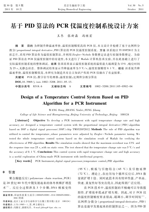
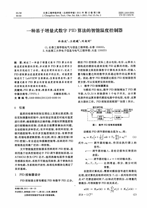
Figure 5. Heating control module circuit schematic diagram 图 5. 加热控制模块电路原理图
Copyright © 2013 Hanspub
39
基于增量式 PID 算法的高精度温控系统的设计
具体在本设计中温度采集频率为 10 Hz(100 ms), 每秒钟采样的温度值通过滑动平均值滤波。系统控温 采用模糊算法和增量式 PID 算法相结合的方式,快速 升温阶段采用模糊算法, 恒温时采用增量式 PID 算法。 控温周期 20 秒。为防止加温过冲,当温度接近恒温 点时,采用阶梯式恒温控制方法,如图 6 先将恒温点 设置在小于恒温温度的值,当温度恒定后,再将恒温 点调整为恒温温度。
4. 加热控制模块电路设计
加热控制模块电路设计如图 5。由单片机控制输 出 PID 信号,通过三极管的开关作用,控制固态继电 器的通断,从而达到控制加热片实现以 PID 控制的方 式通断。
将(1)与(2)相减并整理,就可以得到增量式 PID 控制 算法公式为:
uk uk uk 1 e 2ek 1 ek 2 T K p ek ek 1 ek Td k Ti T (3) T Td Td 2Td K p 1 ek K p 1 ek 1 K p ek 2 T T Ti T Aek Bek 1 Cek 2
业、医疗单位、大专院校、科研部门及工矿企业等机 构的实验室里的水浴恒温控制,因为这些应用经常需 要对各种试剂进行蒸馏、干燥、浓缩及恒温加热处理
[1]
,在测控仪器和工业深加工领域,PID 的温控系统
应用还不够深入[2],现有同类温控系统的控温范围一 般都在±1℃的水平[3]。本文在选定温度传感器的基础 设计完成了一套应用在 上, 通过增量式 PID 算法[4-6],
Smart Grid 智能电网, 2013, 3, 37-42 doi:10.12677/sg.2013.32007 Published Online April 2013 (/journal/sg.html)
The High Precision Temperature Control System Based on the Incremental PID Algorithm
基于增量式 PID 算法的高精度温控系统的设计
魏丽君
湖南铁道职业技术学院电气工程系,株洲 Email: 398741983@ 收稿日期:2013 年 1 月 29 日;修回日期:2013 年 2 月 20 日;录用日期:2013 年 2 月 28 日
摘
要:温度传感器被广泛用于工农业生产、科学研究和生活等领域,在温控系统中发挥着重要的作用。而高
if(pwm.ad16<0) pwm.ad16=0; if(pwm.ad16>475) pwm.ad16=475; UART_setchar(0XAA); } if (pwm.ad16>0) { pwm.ad16--; C_out=0; UART_setchar(0X66); } else { C_out=1; UART_setchar(0X67); } }
Lijun Wei
Department of Electrical Engineering, Hunan Railway Professional Technology College, Zhuzhou Email: 398741983@ Received: Jan. 29th, 2013; revised: Feb. 20th, 2013; accepted: Feb. 28th, 2013 Copyright © 2013 Lijun Wei. This is an open access article distributed under the Creative Commons Attribution License, which permits unrestricted use, distribution, and reproduction in any medium, provided the original work is properly cited.
基于增量式 PID 算法的高精度温控系统的设计
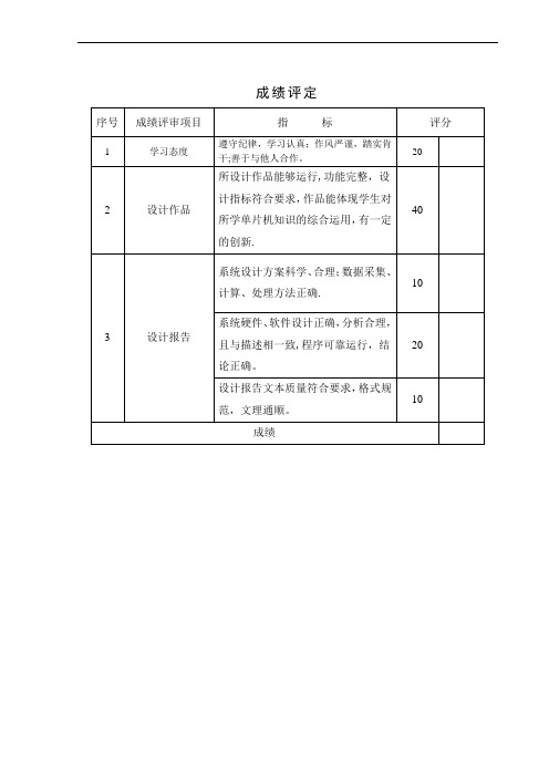
Figure 3. ADS1110 write operation sequence 图 3. ADS1110 写操作时序
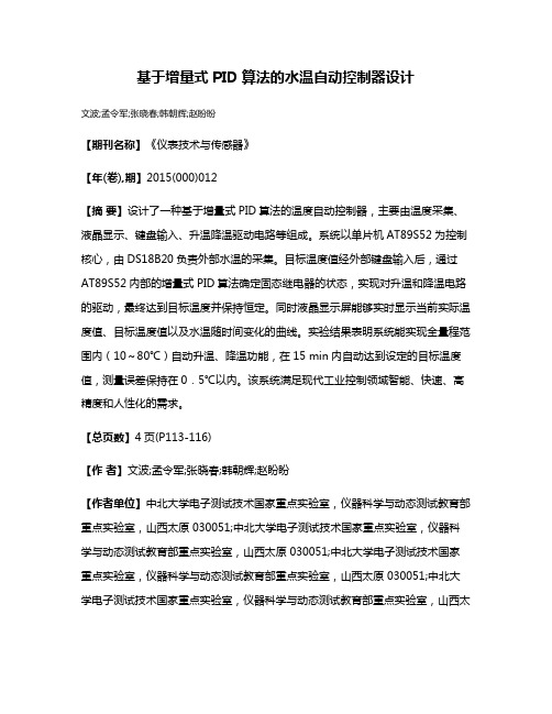
Figure 4. Temperature acquisition and A/D conversion module 图 4. 温度采集与 A/D 转换模块
Abstract: Temperature sensors are widely used in industrial and agricultural production, scientific research and other areas of life, and play an important role in the temperature control system. The high precision temperature control system has a very important place in measurement and control instrument development and deep processing industry. So, it has very strong application value and practical significance to design and develop a high precision temperature control system. In this paper, based on the hardware design of temperature control system, through incremental PID algorithm, a design of a temperature control in the range of ±0.1˚C high precision temperature control system is completed, when compared with the existing similar temperature control systems, precision increases nearly 10 times. Keywords: Temperature Sensor; High Precision Temperature Control System; Incremental PID Algorithm
3. 温度采集与 A/D 转换模块的设计
集成温度传感器采用 AD590, 它是美国模拟器件 公司生产的集成两端感温电流源,是电流型温度传感 器 ,通过对电流的测量可得到所需要的温度值流过 器件的电流(μA) 等于器件所处环境的热力学温度( 开 尔文)度数,即:
IT T 1 μA K
[8]
式中:IT:流过器件(AD590)的电流,单位 μA。T:热 力学温度,单位 K。 其工作原理是:在被测温度一定时,AD590 相当 于一个恒流源,把它和 5~30 V 的直流电源相连,并 在输出端串接一个 1 kΩ 的恒值电阻,那么,此电阻 上流过的电流将和被测温度成正比,此时电阻两端将 会有 1 mV/K 的电压信号。
精度的温控系统在测控仪器开发以及工业深加工过程中占有相当重要的地位,因此设计开发高精度的温控系统 具有很强的应用价值和现实意义。本文在温控系统硬件设计的基础上,通过增量式 PID 算法,设计完成了一套 控温范围在±0.1℃的高精度温控系统,相比现有同类温控系统,精度提高近 10 倍。 关键词:温度传感器;高精度温控系统;增量式 PID 算法
△-∑调节器和数字滤波器组成。 调节器测量正模拟输
ቤተ መጻሕፍቲ ባይዱ
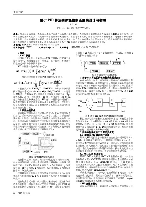
2. 系统硬件框图及原理
硬件系统以 P89V669 单片机为核心, 由温度采集 模块、A/D 转换模块、加热控制模块、温度补偿模块 以及串口等构成。总体硬件框图如图 1。 整个系统的工作原理是:由温度采集模块采集控 制区域的实时温度值, 通过 A/D 转化模块转化后传送 给单片机处理,单片机通过对当前温度的判断,不断 调整加热模块的 PID 输出控制参数,使得温度值往设 定值越来越靠近并保持恒定,变化范围不超过 0.1℃。
1. 引言
高精度的温控系统在测控仪器开发以及工业深 加工过程中占有相当重要的地位,在工业深加工的过 程中,对过程的控制以及实时温度的控制提出了很高 的要求,在产品一致性上,要求温度基本维持恒定。 设计和开发高精度的温控系统具有很强的应用价值。 国内外的基于 PID 的温控系统一般应用于化工
Copyright © 2013 Hanspub
5. 增量式 PID 算法设计实现
增量式 PID 控制公式:
u k k p e k e k 1 ki e k kd e k 2e k 1 e k 2
其中 (1)
T T 2T A K p 1 d , B K p 1 d T T T i T C Kp d T ,