施克旋转编码器ATM60说明书
SICK 20 Incremental Encoder 编码器说明书

Installation InstructionsSize20Incremental Encoder,Bulletin845TIMPORTANT:SAVE THESE INSTRUCTIONS FOR FUTURE USE. SpecificationsElectricalCode Format Incremental(A,AB or ABZ channels)Quadrature90°±22°Channel A leads B CCWSymmetry50%±10%Zero Index Channel Gated1/2cyclePower Requirements Determined by catalog number:5V DC±5%@150mA maximum11--20V DC@150mA maximum24V DC@150mA maximumFrequency Response Data:210kHz Zero index:210kHzOperating Speed(Data)(100kHz x60)/pulses per revolution=RPM or15,000 RPM,whichever is lowerResolution Up to3000PPR on code diskOutput Drive Capability Push-Pull Single Ended Driver=±20mA Differential line driver=±20mAMechanicalStarting Torque 2.5Ncm typical[3.5in-oz] Running Torque 2.5Ncm typical[3.5in-oz]Slew Speed15,000RPMShaft Loading Axial:359N[80lbs]Radial:359N[80lbs](10mm,3/8in shafts)180N[40lbs](6mm,1/4in shafts)Shaft Size6mm,10mm,6.4mm[1/4in],9.517mm[3/8in]diameter EnvironmentalHousing NEMA Type4,IP66(IEC529)Temperature0°C to+60°C(+32°F to+140°F)—operating--25°C to+90°C(--13°F to+194°F)—storageHumidity98%,noncondensingShock50g(11ms duration)Vibration20g(5to2000Hz)Approximate ShipWeight 0.44kg(14oz)Flexible ShaftCouplingsAccessoriesDescription Part NumberHigh Performance Flexible Coupling845--FC--*--*Measuring Wheels845--MW--A--*Servo Clamps845--SCPre-Wired Cables845--CA--*--*Mating Connectors845--6P,845--7P,845--10PDifferential Encoder Buffer Board845--BB*See Sensor catalog for selection.Selection Guide845T—D Z13E CR—Ca b c d e f gaMounting ConfigurationCode DescriptionD Square FlangeHServo with Face Mount HolesLServo withoutFace Mount HolesbShaft OptionsCode Description A6mm Diameter B10mm Diameter C1/4in Diameter Z3/8in Diameter K6mm w/FlatL10mm w/Flat M1/4in w/FlatN3/8in w/Flatc Electrical Options Code Description15V DC in,5V DC DLD Out25V DC in,5V DC P--P Out311--24V DC in, 11--24V DC P--P Out411--20V DC in, 5V DC DLD Out524V DC in, 5V DC DLD Out611--24V DC in, 11--24V DC DLD outDLD=Differential Line DriverP--P=Push-Pull Single Ended DriverdSignal Options Code Description1Channel A Only2Channel A and B3Channel A,B,and ZeConnection OptionsCode DescriptionA6Pin ConnectorB7Pin ConnectorE10Pin ConnectorP Pigtail CableThis option not available withElectrical Option codes:“1,”“4,”“5”or“6.”gMating Connector/CableLengthCode DescriptionBlank Without Mating ConnectorC With Mating Connector11m(3.28ft)Cable Length55m(16.4ft)Cable Length99m(29.52ft)Cable LengthThese options not available with ConnectionOptions code:“P.”These options not available with ConnectionOptions code:“A,”“B,”&“E.”fResolutionCode Description(PPR)AG1AM5BG10CA50CB60CE64CF80CG100DB120DF150EB180CH200CJ250CC254CW256EG300CK360CL400CM500DW512EH600DG720DL800LG900CN1000FW1024EL1200CD1250RF1280CU1472EM1500FL1600CP1800DN2000CS2048HL2400CR2500CY2540LJ2750EN3000Electrical ConnectionsDifferential Line DriverOutputChannel B*Channel B*(Index)Channel Z*Channel Z*Logic 1Logic 0(CCW Rotation Shown)90+/--6-Pin Connector (ACS02E14S--6P (023))Push-Pull Outputs Pin FunctionPinFunction A DC Return D Channel B Output B DC+Input E Channel A Output CChannel Z OutputFNo Connection7-Pin Connector (ACS02E16S--1P (023))Push-Pull Outputs Pin Function PinFunction A Channel A Output E No Connection B Channel B Output F DC Return C Channel Z Output G No Connection DDC+Input—No Connection10-Pin Connector (ACS02E18S--1P (023))Push-Pull,Differential Line Driver Outputs Pin Function PinFunctionA Channel A Output F DC ReturnB Channel B Output G NoConnection C Channel Z Output H Channel A Output D DC+Input I Channel B OutputENo ConnectionJChannel Z OutputNot included with push-pull outputsPush-Pull Single End Driver OutputChannel Channel B*(Index)Channel Z*Logic 1Logic 0(CCW Rotation Shown)*Optional Channels90+/--22°CableCable Differential Line Driver Outputs Wire PairWire ColorFunctionRed/Black Red DC+Input Black DC Return White/Black White Channel A Output Black Channel A Output Blue/Black Blue Channel B Output Black Channel B Output Green/BlackGreen Channel Z Output BlackChannel Z OutputCablePush-Pull Outputs Wire PairWire ColorFunctionRed/Black Red DC+Input Black DC Return White/BlackWhite Channel A Output Black Not Connected Blue/Black Blue Channel B Output Black Not Connected Green/BlackGreen Channel Z Output BlackNot ConnectedDimensions—mm (inches)Servo Mount-32UNF--2B x (0.22)Deep on (1.625)Dia.Bolt Circle,4Places—90°Apart4--402B x Deep on Dia.Bolt Circle,3Places—120°ApartDeep on a Bolt Circle,3°ApartFace Square Flange Mount3.96(0.156)4Mtg.Connector Dimensions Dimension Code Radial Connector OptionsLengthAACS02E14S--6P (6pin)2.272(57.7)ACS02E16S--1P (7pin) 2.460(62.5)ACS02E18--1P (10pin)2.691(68.9)Shaft Diameter DimensionsDimension CodeShaft Diameter OptionsB0.3749+0.0000,--0.0005(9.52)Diameter0.2499+0.0000,--0.0005(6.35)Diameter 10mm +0.000mm,--0.013mm Diameter 6mm +0.000mm,--0.013mm DiameterFlat DimensionsCodeDimension “A”K 5.3mm (0.21in)L 9.1mm (0.36in)M 5.5mm (0.22in)N8.6mm (0.34in)Publication 75008--187--01(A)November 2003Printed in USA。
编码器快速使用说明

目 录
第一章 产品介绍.....................................................................................................................................2 1.1 产品概述................................................................................................................................... 2 1.2 产品主要功能特点..................................................................................................................... 2 1.3 设备线缆连接............................................................................................................................ 3 第二章 基本操作.....................................................................................................................................4 2.1 开机.......................................................................................................................................... 4 2.2 关机.......................................................................................................................................... 4 2.3 登录.......................................................................................................................................... 4 2.4 预览.......................................................................................................................................... 5 2.5 报警功能....................................................................................................................................5 2.5.1 移动侦测........................................................................................................................ 5 2.5.2 视频分析........................................................................................................................ 6 2.6 云台控制................................................................................................................................... 9 2.7 网络设置................................................................................................................................... 9 2.8 通道管理................................................................................................................................. 10 2.9 公网访问设备(云操作).........................................................................................................10 2.9.1 向导.............................................................................................................................. 11 2.9.2 按用户登录,管理设备(按用户登录,可以管理多台设备)..........................................14 2.9.3 按序列号登录,访问设备............................................................................................... 15 第三章 远程监控................................................................................................................................... 17 1.远程监控.....................................................................................................................................17 1.1 多机管理平台软件 CMS....................................................................................................... 17 1.2 web 监控........................................................................................................................... 17 2.基本远程操控............................................................................................................................ 19 2.1 画面分割.......................................................................................................................... 19 2.2 回放................................................................................................................................. 19 2.3 日志................................................................................................................................. 19 2.4 本地配置.......................................................................................................................... 19 2.5 通道操控.......................................................................................................................... 19 2.6 远程进行设备端配置.........................................................................................................19
旋转编码器详细讲解

增量式编码器的A.B.Z 编码器A、B、Z相及其关系TTL编码器A相,B相信号,Z相信号,U相信号,V相信号,W相信号,分别有什么关系?对于这个问题的回答我们从以下几个方面说明:编码器只有A相、B相、Z相信号的概念。
所谓U相、V相、W相是指的电机的主电源的三相交流供电,与编码器没有任何关系。
“A相、B相、Z相”与“U相、V相、W相”是完全没有什么关系的两种概念,前者是编码器的通道输出信号;后者是交流电机的三相主回路供电。
而编码器的A相、B相、Z相信号中,A、B两个通道的信号一般是正交(即互差90°)脉冲信号;而Z相是零脉冲信号。
详细来说,就是——一般编码器输出信号除A、B两相(A、B两通道的信号序列相位差为90度)外,每转一圈还输出一个零位脉冲Z。
当主轴以顺时针方向旋转时,输出脉冲A通道信号位于B通道之前;当主轴逆时针旋转时,A通道信号则位于B通道之后。
从而由此判断主轴是正转还是反转。
另外,编码器每旋转一周发一个脉冲,称之为零位脉冲或标识脉冲(即Z相信号),零位脉冲用于决定零位置或标识位置。
要准确测量零位脉冲,不论旋转方向,零位脉冲均被作为两个通道的高位组合输出。
由于通道之间的相位差的存在,零位脉冲仅为脉冲长度的一半。
带U、V、W相的编码器,应该是伺服电机编码器A、B相是两列脉冲,或正弦波、或方波,两者的相位相差90度,因此既可以测量转速,还可以测量电机的旋转方向Z相是参考脉冲,每转一圈输出一个脉冲,脉冲宽度往往只占1/4周期,其作用是编码器自我校正用的,使得编码器在断电或丢失脉冲的时候也能正常使用。
ABZ是编码器的位置信号,UVW是电机的磁极信号,一般用于同步电机; AB对于TTL/HTL编码器来说,AB相根据编码器的细分度不同,每圈有很多个,但Z相每圈只有一个;UVW磁极信号之间相位差是120度,随着编码器的角度转动而转动,与ABZ 之间可以说没有直接关系。
/######################################################## #####编码器A+A-B+B-Z+Z-怎么用分别代表什么意思?这种编码器的输出方式为长线驱动(line driver),其中A+A-B+B-Z+Z-为输出的信号线,增量编码器给出两相方波,它们的相位差90°(电气上),通常称为A通道和B通道。
旋转编码器调整方法word精品文档10页
四:旋转编码器的调整增量式编码器的相位对齐方式在此讨论中,增量式编码器的输出信号为方波信号,又可以分为带换相信号的增量式编码器和普通的增量式编码器,普通的增量式编码器具备两相正交方波脉冲输出信号A和B,以及零位信号Z;带换相信号的增量式编码器除具备A/B/Z 输出信号外,还具备互差120度的电子换相信号U/V/W,U/V/W各自的每转周期数与电机转子的磁极对数一致。
带换相信号的增量式编码器的U/V/W电子换相信号的相位与转子磁极相位,或曰电角度相位之间的对齐方法如下:1.用一个直流电源给电机的U/V绕组通以小于额定电流的直流电,U入,V出,将电机轴定向至一个平衡位置.2.用示波器观察编码器的U相信号和Z信号.3.调整编码器转轴与电机轴的相对位置.4.一边调整,一边观察编码器U和Z相信号跳变沿,直到Z信号稳定在高电平上(在此默认Z信号的常态为低电平),锁定编码器与电机的相对位置关系。
5.来回扭转电机轴,撒手后,若电机轴每次自由回复到平衡位置时,Z信号都能稳定在高电平上,则对齐有效。
撤掉直流电源后,验证如下:1.用示波器观察编码器的U相信号和电机的U/V线反电势波形。
2.转动电机轴,编码器的U相信号上升沿与电机的U/V线反电势波形由低到高的过零点重合,编码器的Z信号也出现在这个过零点上。
上述验证方法,也可以用作对齐方法。
需要注意的是,此时增量式编码器的U相信号的相位零点即与电机UV线反电势的相位零点对齐,由于电机的U相反电势,与UV线反电势之间相差30度,因而这样对齐后,增量式编码器的U相信号的相位零点与电机U相反电势的-30度相位点对齐,而电机电角度相位与U相反电势波形的相位一致,所以此时增量式编码器的U相信号的相位零点与电机电角度相位的-30度点对齐。
有些伺服企业习惯于将编码器的U相信号零点与电机电角度的零点直接对齐,为达到此目的,可以:1.用3个阻值相等的电阻接成星型,然后将星型连接的3个电阻分别接入电机的UVW三相绕组引线;2.以示波器观察电机U相输入与星型电阻的中点,就可以近似得到电机的U相反电势波形。
多功能滑动旋转编码器说明书
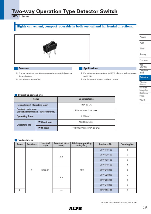
267Power Push SlideRotary Encoders Jog Shuttle Telephone -hook Detector Vibration Sensors Dual-in-line Package TypeMulti ControlDevicesTACTHighly convenient, compact operable in both vertical and horizontal directions.ApplicationsA wide variety of operation components is possible based on the application.Dip soldering is possible.FeaturesFor detection mechanisms in DVD players, audio players,and VCRsFor detecting tray sizes of photo copiersOperating life1mA 5V DC0.3N max.500m max. / 1 max.100,000 cyclesRating max. Resistive load ItemsSpecificationsContact resistanceInitial performance / After lifetime Operating force100,000 cycles 1mA 5V DCWithout loadWith loadTypical SpecificationsProducts LinePoles115.26.82Positions12345678Drawing No.Products No.Terminal pitchmm100Minimum packingunit pcs.Snap-inTerminal styleSPVF110100SPVF120100SPVF130100SPVF140100SPVF210200SPVF220200SPVF230200SPVF2402009SPVF350100For other detailed specifications, see P.300Two-way Operation Type Detector SwitchSPVF Series268Power Push Slide Rotary Encoders Jog Shuttle Telephone -hook DetectorVibration Sensors Dual-in-line Package Type Multi Control Devices TACTON starting positionTotal travel position4.52.84-14.76.36.85910.71.15.2ø15.81.23.5 5.44-1.14-1ø155ON starting positionTotal travel position4.52.84-14.75.756.2910.71.15.2 ø15.81.23.5 5.44-1.14-1ø151235.44-1.14-1ø1545.44-1.14-1ø15510.71.16.8ø17.41.23.562.84-16.27.88.359ON starting positionTotal travel position74-1.14-1ø15Unit : mmDimensionsStyleNo.PC board mounting hole dimensionsTwo-way Operation Type Detector Switch SPVF Series5.25.8ON starting positionTotal travel position 4.513.62.84-115.2595.72.61.710.71.1ø11.23.5ON starting positionTotal travel position4.52.84-17.89.9510.7597.214.710.71.1ø11.23.55.25.8269Power Push Slide RotaryEncoders Jog Shuttle Telephone -hookDetectorVibration Sensors Dual-in-line Package TypeMulti Control Devices TACTUnit : mmDimensionsStyleNo.PC board mounting hole dimensions610.71.16.8ø17.41.23.562.84-16.27.257.759ON starting positionTotal travel position74-1.14-1ø157810.71.16.8ø17.41.23.5615.12.84-116.7595.72.61.7Total travel position ON starting position4-1.154-17ø14-1.154-17ø110.71.16.8ø17.41.23.562.84-19.311.4512.25914.77.2Total travel positionON starting position95-ø16.8510.7583421Terminal No.1234123Terminal No.123Circuit DiagramTwo-way Operation Type Detector Switch SPVF Series9.95Total travel positionON starting position3.251.15.32.72.958.3842-ø111.48.683-152-15.57.4199.50.7300Power Push Slide Rotary Encoders Jog Shuttle Telephone -hook Detector Vibration Sensors Dual-in-line Package Type Multi Control Devices TACTSeriesItemsOperating temperature rangeRating max. Resistive loadElectrical performanceMechanical performance DurabilityEnvironmental performanceInitial contact resistance Insulation resistance Voltage proof Robustness ofterminal Robustness ofactuator SolderabilityOperating life without loadOperating life with loadColdDry heat Damp heatResistancetosolderingheatManual solderingDip soldering Reflow solderingVibration Products SpecificationsSPPB0.1A 30VDC 0.1A 30V DC50,000cycles 2 max.50,000cycles 2 max.SPVE SPPW8 10 to 60 0.1A 30VDC 0.1A 12VDC 1 max.1 max.500m max.3N for 1 min.3Nfor 1 min.10N10N20 2 for 96h25 2 for 96h20 2for 96h100,000cycles 2 max.0.1A 30V DC 100,000cycles 2 max. 0.1A 12V DC 50,000cycles 1 max.2 max.SPVM 1mA 5V DC 1N for 1 min.5N50,000cycles 5 max.1mA 5V DC 50,000cycles 5 max.260 5 ,5 1s255 5 ,5 1s350 10 , 3s 10 350 5 , 3s max.100M min.100V DC 100V AC for 1 min.0.5N for 1 min.5N230 5 , 3 0.5s85 2 for 96h40 2 , 90 to 95%RH for 96h50,000cycles 1 max.Please see P.300350 5 , 3s max.300 5 , 5s max.10 to 55 to 10Hz/min., the amplitude is 1.5mm for all the frequencies,in the 3 direction of X, Y and Z for 2 hours respectively500m max.SPVF 3N for 30 s 3N for 1 min.1N10N5N 40 2 for 96h100,000cycles 1 max.1mA 5V DC 100,000cycles 1 max.260 5 ,5 1s260 5 ,5 1s300 10 , 3s 10 SSCT SSCU 0.1A 12V DC 20m max.70m max.100M min.250V DC 250V AC for 1 min.20 2 for 96h10,000cycles 40m max.10,000 cycles 100m max. 0.1A 12V DC 10,000cycles 60m max. 0.1A 12V DC 10,000cycles 150m max.350 10 ,3s100.5N for 1 min.5NSPVP1mA 5V DC 5 max.100M min.100V DC 100V AC for 1 min.50,000cycles 10 max.1mA 5V DC 50,000cycles10 max.350 5 , 3s max.Please see P.302Detector Switches。
DGS 60 65 66 增量编码器数据手册说明书
IDGS 60, DGS 65 and DGS 66: Incremental Encoders for rough environmental conditionsDA T ASH E E TIncremental encoders in the DGS 60, DGS 65 and DGS 66series are in use world-wide under the toughest environmental conditions.The rugged construction – up to IP 67 degree protection – and the individual adaptation of the design to the requirements of the user are the outstanding features of this series. Resolutions up to 10,000 lines are available.Select your individual encoder!Possible product variants:6 and 10 mm solid shafts with servo flange or face mount flange,through or blind hollow shafts with connector or cable outlet, TTL or HTL interface.Thanks to this wide variety of products, there are numerous possible uses, for example in:·machine tools·textile machines ·woodworking machines ·packaging machinesPIN Signal Signal Core colour ExplanationHTLTTL (cable outlet)1N. C.B black Signal line 2N. C.Sense +grey Connected internally to U s 3Z Z lilac Signal line 4N. C.Z yellowSignal line 5A A white Signal line 6N. C.A brown Signal line 7N. C.N. C.orange N. C.8B B pinkSignal line 9Screen Screen Housing potential 10GND GND blue Ground connection 11N. C.Sense –green Connectedinternally to ground 12U sU sredPower supply 1)1)Potential free to housing N. C. =Not Connected2SICK-STEGMANNIncremental Encoder DGS 60, face mount and servo flangeServo or face mount flange Connector or cable outlet Protection class up to IP 67Electrical Interfaces TTL and HTLView of the connector M23 fitted to the encoder body1R = bending radius min. 40 mm1R = bending radius min. 40 mm 1General tolerances according to DIN ISO 2768-mkGeneral tolerances according to DIN ISO 2768-mk1zero pulse markingzero pulse markingd ee p (7 d e e p )3DGS 604)To DIN EN 61000-6-2and DIN EN 61000-6-33)Condensation not permitted 2)At speeds > 6000 rpm the shaft seal must be removed1)For an encoder with connector outlet SICK-STEGMANN 5)To DIN EN 60068-2-276)To DIN EN 60068-2-67)With mating connector fitted4SICK-STEGMANNIncremental Encoder DGS 60, face mount and servo flangeA / AB / BZ / ZServo or face mount flangeConnector or cable outlet Protection class up to IP 67Electrical Interfaces TTL and HTL5SICK-STEGMANN DGS 606Incremental Encoder DGS 65, blind hollow shaftSICK-STEGMANNCollets for shaft diameter 6, 8, 10 and 12 mmConnector or cable outlet Electrical Interfaces TTL and HTLR = bending radius min. 40 mm1General tolerances according to DIN ISO2768-mk1PIN Signal Signal Core colour ExplanationHTL TTL (cable outlet)1N. C.B black Signal line 2N. C.Sense +grey Connected internally to U s 3Z Z lilac Signal line 4N. C.Z yellow Signal line 5A A white Signal line 6N. C.A brownSignal line 7N. C.N. C.orange N. C.8B B pinkSignal line 9Screen Screen Housing potential 10GND GND blue Ground connection 11N. C.Sense –green Connectedinternally to ground 12U sU sred Power supply 1)1)Potential free to housing N. C. =Not ConnectedView of the connector M23 fitted to the encoder body7SICK-STEGMANN DGS 652)Condensation not permitted4)To DIN EN 60068-2-275)To DIN EN 60068-2-66)With mating connector fitted3)To DIN EN 61000-6-2and DIN EN 61000-6-31)For an encoder with connector outlet8Incremental Encoder DGS 65, blind hollow shaftSICK-STEGMANNCollets for shaft diameter6, 8, 10 and 12 mmConnector or cable outlet Electrical Interfaces TTL and HTLA / AB / BZ / Z9SICK-STEGMANNDGS 651)Collets for 6, 8, 10 and 12 mmas accessories, separate order item (see below).2) Only possible with interface 4 … 6V, TTL (RS 422) = A10Incremental Encoder DGS 66, blind and through hollow shaftSICK-STEGMANN100 to 10,000 number of lines per revolutionElectrical InterfacesTTL and HTLR = bending radius min. 30 mm1General tolerances according to DIN ISO 2768-mk R = bending radius min. 30 mm1General tolerances according to DIN ISO 2768-mk11Core colour Explanation Core colour ExplanationHTL TTL black N. C.black B lilac Z lilac Z yellow N. C.yellow Z white A white A brown N. C.brown A pink B pink B Screen ScreenScreen Screenblue Ground connection blue Ground connection redPower redPower supply 1)supply 1)1)Potential free to housing N. C. =Not Connected11SICK-STEGMANN DGS 664)To DIN EN 60068-2-61)Condensation not permitted 2)To DIN EN 61000-6-2and DIN EN 61000-6-33)To DIN EN 60068-2-2712Incremental-Encoder DGS 66, blind and through hollow shaftSICK-STEGMANN100 to 10,000 number of linesper revolutionElectrical Interfaces TTL and HTLA / AB / BZ / Z13SICK-STEGMANNDGS 661)Collets for 6, 8, 10, 12, 14, 15 mm and 1/2" as accessories, separate order item (see below).14Accessories Connection systems/Mounting systemsSICK-STEGMANNapprox. 5515SICK-STEGMANN DGS 60General tolerances according to DIN ISO 2768-mkCheese-head screw M2,5x8 DIN912 A216SICK-STEGMANNGeneral tolerances according to DIN ISO 2768-mkGeneral tolerances according to DIN ISO 2768-mkGeneral tolerances according to DIN ISO 2768-mkAccessories Mounting systemsSpring washer (4x)Hexagonal nut (4x)(secure with Loctite 241)d e e p )17SICK-STEGMANN DGS 60General tolerances according to DIN ISO 2768-mk General tolerances according to DIN ISO 2768-mkGeneral tolerances according to DIN ISO 2768-mkGeneral tolerances according to DIN ISO 2768-mk18SICK-STEGMANNGeneral tolerances according to DIN ISO 2768-mk General tolerances according to DIN ISO 2768-mkAccessories Mounting systems/ColletsDGS 6019 SICK-STEGMANNSICK AG • Industrial Sensors • Waldkirch • Germany • Stegmann GmbH & Co. KG • Donaueschingen • Germany • www.sick-stegmann.de8 010 302/03-04 • D M /3/2000 • P r i n t e d i n G e r m a n y (07.04) • S u b j e c t t o c h a n g e w i t h o u t p r i o r n o t i c e • T h e s p e c i f i e d p r o d u c t f e a t u r e s a n d t e c h n i c a l d a t a d o n o t r e p r e s e n t a n y g u a r a n t e e • 01 A 4S t g - - 2c i n t 16Contact:A u s t r a l i aPhone +61 3 9497 41001800 33 48 02 – tollfreeE-Mail **************.au B e l g i u m /L u x e m b o u r g Phone +32 (0)2 466 55 66E-Mail ************B r a s i lPhone +55 11 5091-4900E-Mail ************.br C e s k á R e p u b l i k aPhone +420 2 57 91 18 50E-Mail ************C h i n aPhone +852-2763 6966E-Mail ************.hk D a n m a r kPhone +45 45 82 64 00E-Mail ************D e u t s c h l a n dPhone +49 (0)2 11 53 01-250E-Mail ***************E s p a ñaPhone +34 93 480 31 00E-Mail ************F r a n c ePhone +33 1 64 62 35 00E-Mail ************G r e a t B r i t a i nPhone +44 (0)1727 831121E-Mail ************.uk I t a l i aPhone +39 011 797965E-Mail ********************J a p a nPhone +81 (0)3 3358 1341E-Mail ************K o r e aPhone +82-2 786 6321/4E-Mail ******************N e d e r l a n d sPhone +31 (0)30 229 25 44E-Mail ************N o r g ePhone +47 67 81 50 00E-Mail ******************Ös t e r r e i c hPhone +43 (0)22 36 62 28 8-0E-Mail **************P o l s k aPhone +48 22 837 40 50E-Mail ************S c h w e i zPhone +41 41 619 29 39E-Mail ***************S i n g a p o r ePhone +65 6744 3732E-Mail *****************.sg S u o m iPhone +358-9-25 15 800E-Mail ************S v e r i g ePhone +46 8 680 64 50E-Mail ************T a i w a nPhone +886 2 2365-6292E-Mail *****************.net U S APhone +1 937-454-1956E-Mail ******************More representatives and agencies in all major industrial nations at 。
SICK增量旋转编码器选型手册

43.1 (1.70)
Ø 60 (2.36) 3 x 120°
Ø0.05 C
其它公差遵循DIN ISO 2768-mk标准 电缆直径- =5.6±0.2mm 弯曲半径 R=30mm
3 x M4 (6-deep)
Ø 48±0.05 (1.89)
夹紧法兰型外形尺寸图,M12 或 M23 插头式
3 x M4 Ø 48±0.05 (1.89) (6-deep)
01000 01024 01250
00200 02048
B型-可选择的分辨率 00050 00100 00200 00250
00300 00314 00360
00500 00512 00720
01000 01024 01250
00200 02048 02500 03600
04000 04096 05000
外壳防护等级IEC60529
质量 EMC5)
DFS60 实心轴,夹紧法兰型 O/ 60mm O/ 10 x 19 mm 0,5 Ncm 0,3 Ncm 6,2 gcm2
5 x 10⁵ rad/s2 径向 轴向 3 x 10⁹ 圈
90% 冲击3) 振动4) 外壳部分 实心轴部分 0.3kg
E
10,000 min-1 80 N 40 N
DFS60全系列产 品
DFS60夹紧法 兰型 外形 尺 寸 : 10× 19mm
DFS60伺服法 ቤተ መጻሕፍቲ ባይዱ型
运
外形尺寸: 6×10mm
动
控
制
DFS60盲孔型
传
轴径范围: 8- 15mm
感
器
分辨率: 电气输出接口: 最大转动速度: 工作温度范围: 最大输出频率: 外壳防护等级:
SICK编码器参数解释

从轴端观察,轴向右侧旋转。
Rotation direction, counterclockwise (ccw)(逆时针旋转方向) 从轴端观察,轴向左侧旋转。
CW
CCW
当轴顺时针旋转时,位置值增加
July, 2014
Gareth Zheng | Confidential
20
编码器参数
性能参数 Resolution(分辨率)
可以结合这2个数值。但单个数值必须在其限制范围内。 例如,轴偏移 0.3mm 并且轴摆动约 ± 0.1mm。然后,轴的移动范围是从 +0.2mm 到 + 0.4mm.
解释:
轴向移动
径向移动
机械部分 /电机
July, 2014
Gareth Zheng | Confidential
19
编码器参数
机械接口 Rotation direction, clockwise (cw)(顺时针旋转方向)
SICK 编码器参数解释
Gareth Zheng Technical Support & Service July, 2014
编码器基本分类
增量与绝对值
July, 2014
Gareth Zheng | Confidential
2
编码器基本分类
直线测量
July, 2014
Gareth Zheng | Confidential
机械接口 允许动态径向驱动装置轴位移
动态径向轴位移是轴的误差。它由轴的摆动产生。这误差是动态的,因为 它由轴的旋转移动产生。对于DFS60,最大值允许到± 0.1mm。
July, 2014
Gareth Zheng | Confidential
旋转编码器工作方式图解

旋转编码器旋转编码器是由光栅盘(又叫分度码盘)和光电检测装置(又叫接收器)组成。
光栅盘是在一定直径的圆板上等分地开通若干个长方形孔。
由于光栅盘与电机同轴,电机旋转时,光栅盘与电机同速旋转,发光二极管垂直照射光栅盘,把光栅盘图像投射到由光敏元件构成的光电检测装置(接收器)上,光栅盘转动所产生的光变化经转换后以相应的脉冲信号的变化输出。
编码器码盘的材料有玻璃、金属、塑料等。
玻璃码盘是在玻璃上沉积很薄的刻线,其热稳定性好,精度高。
金属码盘直接以通和不通刻线,不易碎,但由于金属有一定的厚度,精度就有限制,其热稳定性也比玻璃的差一个数量级。
塑料码盘成本低廉,但精度、热稳定性、寿命均要差一些。
编码器以信号原理来分,有增量式编码器(SPC)和绝对式编码器(APC),顾名思义,绝对式编码器可以记录编码器在一个绝对坐标系上的位置,而增量式编码器可以输出编码器从预定义的起始位置发生的增量变化。
增量式编码器需要使用额外的电子设备(通常是PLC、计数器或变频器)以进行脉冲计数,并将脉冲数据转换为速度或运动数据,而绝对式编码器可产生能够识别绝对位置的数字信号。
综上所述,增量式编码器通常更适用于低性能的简单应用,而绝对式编码器则是更为复杂的关键应用的最佳选择--这些应用具有更高的速度和位置控制要求。
输出类型取决于具体应用。
一:增量式旋转编码器工作原理增量式旋转编码器通过两个光敏接收管来转化角度码盘的时序和相位关系,得到角度码盘角度位移量的增加(正方向)或减少(负方向)。
增量式旋转编码器的工作原理如下图所示。
图中A、B两点的间距为S2,分别对应两个光敏接收管,角度码盘的光栅间距分别为S0和S1。
当角度码盘匀速转动时,可知输出波形图中的S0:S1:S2比值与实际图的S0:S1:S2比值相同,同理,当角度码盘变速转动时,输出波形图中的S0:S1:S2比值与实际图的S0:S1:S2比值仍相同。
通过输出波形图可知每个运动周期的时序为:我们把当前的A、B输出值保存起来,与下一个到来的A、B输出值做比较,就可以得出角度码盘转动的方向,如果光栅格S0等于S1时,也就是S0和S1弧度夹角相同,且S2等于S0的1/2,那么可得到此次角度码盘运动位移角度为S0弧度夹角的1/2,再除以所用的时间,就得到此次角度码盘运动的角速度。
SICK公司介绍

H I P E RFAC E电 机 反 馈 系 统 接 口 技 术 HIPERFACE接口的SinCos系列编码器仅用8条线就能提 供SinCos增量信号和RS485的绝对位置信号。绝对位 置信息通过RS485接口传送,当编码器一上电,就可识 别 此 绝 对 位 置 的 信 息 , SinCos增 量 信 号 可 通 过 后 继 A/D转换器转换为高达几百万分辨率的数字脉冲信号, 使电机在低速运行情况下也具备非常好的“动态速度调 节 性 能 ”。 SICK-STEGMANN的 “ HIPERFACE” 伺 服 反馈编码器能满足最苛刻的应用要求,并赢得了世界上 大部分“驱动控制器”厂商的青睐。
OES3第三代芯片技术 第三代芯片技术(OES3)性能上采用了高精度的阵列式 光敏接收二极管和先进的芯片技术,抗干扰能力强、具 有精密度的BGS(背景遮蔽功能)对颜色不敏感,对于 黑色、透明、反光率大等物体的均能可靠的检测。同时 OES3传感器还具备电子调节功能,即使在震动的场合 下,也可以保证光斑不会漂移。
SICK I 9
产品介绍
Products and Solutions
DIV05
DIV05自动识别系统 DIV05系列产品主要包括固定式条码扫描器、手持 式条码扫描器、全方位条码扫描系统、无线射频识 别 系 统 ( RFID) 、 激 光 测 量 系 统 、 体 积 测 量 系 统、ALIS机场行李分拣系统等,可用于可靠地进行 产品质量追溯、安全防撞及物体测量等。在电子、 汽车、物流等许多行业得到广泛应用。
Products and Solutions
SICK公司提供范围广泛的工业应用传感器,产品广泛应用于:电子半导体工业、汽车行业、食品饮料及烟草 行业、物流仓储系统、工业流程、环境测量等各行各业,这些工业传感器主要用来:对物体进行记录、计 数、分类和定位,检测物体的外形和位置,并能进行颜色和表面特性的区分,即使在恶劣环境的工况下仍能 正常工作。SICK公司的工业传感器优化了生产和物流处理系统,大大提高了生产效率和产品质量。
ATM60-90系列绝对值旋转编码器选型手册(中文版)

1030006 1030007 1030008
动
角度分辨率
0.043°
控
测量误差 重复精度
± 0.25° 0.1°
制
输出接口
SSI,RS422
传
输出码
格雷 码/二 进 制码
感
编码方向
顺时 针/逆 时 针
器
定位时间
0.15ms
接口信号 Clock+,Clock-,Data+,Data-8)
用 于SSI通 讯 模 式 : 最 大 时钟
频 率1MHz; 也 就 是 说 , 时 钟
分ቤተ መጻሕፍቲ ባይዱ率 高达26位
多圈绝对型旋转编码器
ATM60/ATM90: 多圈绝对型旋转编码器 结构坚固,性能可靠
多种接线方式: 插头式,接线端子式
多种输出接口: SSI,Profibus,CANopen和 DeviceNet等;可以满足不 同应用场合的需求。
旋转编码器提供了SSI输出接口 或者RS422参数配置接口也可作为 标准输出接口,并提供连接到
1)在这种 情 况下,用 户将轴封去掉 2)参照DIN IEC 68,2-27部 分 3)参照DIN IEC 68,2-6部分 4)在编 码 器 上 无密封 圈 5)在编 码 器 上 有密封 圈
订货资料
ATM60夹 紧 法 兰 ; 6mm轴 径 ; 电 源 电 压US 10...32V;SSI输 出 接 口/ RS422输出 接 口 1 出 厂 设 置 :4,096脉 冲/圈x 4,096圈 , 格 雷 码 , 电 调 节 信 号"Set”=0
596 运动控制传感器
1 R=最 小 弯 曲 半 径40mm
针脚号
1 2 3 4 5 6 7 8 9 10 11 12
SICK 风力发电系统编码器和电机反馈系统说明书

Maximum reliabilityfor the most aggressive environments i n d u s t r y g u i d EEncoders and motor feedback systems for wind power systemsSICK‘s global presence createsa sense of security – our customers can rely on us to provide them with rapid on-site support and delivery services.2i n d u s t r y g u i d E w i n d p o w E r | s i C KWith the SICK Portfolio, we fulfill your requirements in the field of wind power to the highest of standards:we accompany you every step of the way, from the appli-cation-related consultancy and throughout the engineering process, until a continuous operation with minimal down-times is achieved. Competent, effective and at an optimal cost. You benefit from tailor-made solutions that stand out for their efficiency, directness, sustainability and invest -ment security.3i n d u s t r y g u i d E w i n d p o w E r | s i C K Our wind power industry experts are as deeply rooted in their profession as you are. That means you are always communicating on equal terms with specialists who understand your task re-quirements from the word go. Conclusive solu-tions that can be practically implemented for your individual requirements emerge in the shortest of time frames.Whether you require pitch adjustment, azimuth control or a rotational speed measurement – put us to the test. We would be happy to prove ourselves to you!4i n d u s t r y g u i d E w i n d p o w E r | s i C K2010 - 09s u b j e c t t o c h a n g e w i t h o u t n o t i c eWind power systems must operate at near 100 % availability – hence quality and reliability are extremely important.Variable-speed, pitch-controlled systems are the current state-of-the-art in wind energy system construction. They can be efficiently deployed in the harsh conditions prevalent in both onshore and off-shore operations.Build on SICK‘s compe-tence – a competence demonstrated by over ten years’ experience in this sector and more than 20,000 encoders installed in pitch-controlled systems.Absolute encoder A3M60 – built to last.The A3M60 is an extremely robust absolute multiturn encoder in a 60 mm housing. Even under the harshest environmental conditions both onshore and offshore, the multi-turn encoder achieves maximum reliability via its magnetic, and thus extre-mely robust, scanning func-tion. The innovative and gearless multiturn techno-logy reduces the number of moveable parts on the A3M60 to a minimum. This results in a longer service life with reduced mainte-nance requirements.Absolute encoder AFM60 – the wonder of precision. With 30-bit resolution and a high level of robustness, the new absolute multiturn encoder AFM60 sets a new record. Even its little brother – the absolute singleturn encoder AFS60 – impressive due to its high 18-bit resolution, counts as one of the best products in its5i n d u s t r y g u i d E w i n d p o w E r|s i C K2010-09s u b j e c t t o c h a n g e w i t h o u t n o t i c emarket segment. The singleresolution, as well as thezero point or offset areprogrammable.The two new product fami-lies are especially suitablefor application in the harshconditions prevalent in windpower systems – in otherwords, when the highestlevels of accuracy andavailability are called for.Absolute encoder ATM60– the classic design.The absolute multiturnencoders ATM60 are imple-mented using mechanicaldrives – they deliver therevolution information veryreliably and free from inter-ference. The principle ofoperation is such that asensor scans permanentmagnetic elementsarranged on a magneticscale. This makes highprecision possible due tothe high base resolution of8,192 steps per revolution.6i n d u s t r y g u i d E w i n d p o w E r | s i C K2010 - 09s u b j e c t t o c h a n g e w i t h o u t n o t i c eincremental encoderdgs35 – the robust design. The incremental encoders DGS35 are used in the harshest conditions across the globe. The stable design with an enclosure rating of up to IP 66 ensures for a robust but nevertheless high-resolution incremental encoder. Equipped with a through hollow shaft with a maximum diameter of 30 mm, the DGS family is suitable for use in every application.incremental encoderdFs60 – the rotary design. The DFS60 is a high-reso-lution incremental encoder in a 60 mm design. The DFS60 is unique in its class with a maximum number of lines as high as 65,536. Excellent concentricity and exceptional robustness are achieved thanks to the large distance between the ball bearings which support the encoder shaft. The DFS60 is therefore pre-destined for application in wind power systems.A mechanical interface for all relevant electronic encoder interfaces:incremental (DFS60),absolute (AFS/AFM60) and motor feedback systems (SFS/SFM60).Motor feedback systems sFs60, sFM60 with HipErFACE ® interface. HIPERFACE ® motor feed-back systems comprise a combination of incremen-tal and absolute encoders, successfully uniting the advantages of both enco-der types. They are parti-cularly suited for absolute position finding, with the number of steps being 32,768 per revolution and with a maximum of 4,096 revolutions – that givesa total resolution of 134,217,728 steps in the case of the multiturn design. The speed moni-toring function is enabled via sine/cosine signals. The storing of motor-spe-cific data in the electronic type label as well as the programming function are further important features of these series.The HIPERFACE ® inter-face, which is used in applications across the globe, facilitates the com-missioning of these motor feedback systems.7i n d u s t r y g u i d E w i n d p o w E r|s i C K2010-09s u b j e c t t o c h a n g e w i t h o u t n o t i c epitch + rotational speed r o t a t i o n a l s p e e d pitch + rotational speedSICK AG | Waldkirch | Germany | 8012293/2010-09 ∙ W A S /S Z (2007-10) ∙ W B U S m o d i n t -U S 35Factory automationWith its intelligent sensors, safety sys-tems, and automatic identification appli -cations, SICK provides comprehensive solutions for factory automation.Logistics automationSensors made by SICK form the basis for automating material flows and the optimization of sorting and warehousing processes.process automationOptimized system solutions from SICK ensure efficient acquisition of environ -mental and process data in many indus-trial processes.Our Business Segment ExpertiseNon-contact detecting, counting, • classifying, and positioning of any type of objectAccident protection and personal • safety using sensors, as well as safety software and servicesAutomated identification with bar-• code and RFID reading devices for the purpose of sorting and target control in industrial material flow Detecting volume, position, and con-• tours of objects and surroundings with laser measurement systemsPrecise measurement of gases, • liquids and dust concentrations for continuous monitoring of emissions and the acquisition of process data in production processesGas flow measurements with maxi-• mum accuracy thanks to compact gas metersWorldwide presence with subsidiaries in the following countries:AustraliaBelgium/Luxembourg BrasilCeská republika China danmark deutschland España France Great Britain india israel italia Japan nederland norgeÖsterreich polskarepublic of Korea republika slovenija românia russia schweiz singapore suomi sverige taiwan türkiyeunited Arab Emirates usA/Canada/MéxicoPlease find detailed addresses and additional representatives and agencies in all major industrial nations atHanded over by:。
编码器使用说明书
1.※有网友问:增量旋转编码器选型有哪些注意事项?应注意三方面的参数:1.械安装尺寸,包括定位止口,轴径,安装孔位;电缆出线方式;安装空间体积;工作环境防护等级是否满足要求。
2.分辨率,即编码器工作时每圈输出的脉冲数,是否满足设计使用精度要求。
3.电气接口,编码器输出方式常见有推拉输出(F型HTL格式),电压输出(E),集电极开路(C,常见C为NPN型管输出,C2为PNP型管输出),长线驱动器输出。
其输出方式应和其控制系统的接口电路相匹配。
2.※有网友问:请教如何使用增量编码器?1,增量型旋转编码器有分辨率的差异,使用每圈产生的脉冲数来计量,数目从6到5400或更高,脉冲数越多,分辨率越高;这是选型的重要依据之一。
2,增量型编码器通常有三路信号输出(差分有六路信号):A,B和Z,一般采用TTL电平,A脉冲在前,B脉冲在后,A,B脉冲相差90度,每圈发出一个Z脉冲,可作为参考机械零位。
一般利用A超前B或B超前A进行判向,我公司增量型编码器定义为轴端看编码器顺时针旋转为正转,A超前B为90°,反之逆时针旋转为反转B超前A为90°。
也有不相同的,要看产品说明。
3,使用PLC采集数据,可选用高速计数模块;使用工控机采集数据,可选用高速计数板卡;使用单片机采集数据,建议选用带光电耦合器的输入端口。
4,建议B脉冲做顺向(前向)脉冲,A脉冲做逆向(后向)脉冲,Z原点零位脉冲。
5,在电子装置中设立计数栈。
3.※关于户外使用或恶劣环境下使用有网友来email问,他的设备在野外使用,现场环境脏,而且怕撞坏编码器。
我公司有铝合金(特殊要求可做不锈钢材质)密封保护外壳,双重轴承重载型编码器,放在户外不怕脏,钢厂、重型设备里都可以用。
不过如果编码器安装部分有空间,我还是建议在编码器外部再加装一防护壳,以加强对其进行保护,必竟编码器属精密元件,一台编码器和一个防护壳的价值比较还是有一定差距的。
4.※从接近开关、光电开关到旋转编码器:工业控制中的定位,接近开关、光电开关的应用已经相当成熟了,而且很好用。
编码器使用说明
编码器使用说明光电编码器基础1.1 概述光电编码器是一种集光、机、电为一体的数字化检测装置,它具有分辨率高、精度高、结构简单、体积小、使用可靠、易于维护、性价比高等优点。
近10几年来,发展为一种成熟的多规格、高性能的系列工业化产品,在数控机床、机器人、雷达、光电经纬仪、地面指挥仪、高精度闭环调速系统、伺服系统等诸多领域中得到了广泛的应用。
光电编码器可以定义为:一种通过光电转换,将输至轴上的机械、几何位移量转换成脉冲或数字量的传感器,它主要用于速度或位置(角度)的检测。
典型的光电编码器由码盘(Disk)、检测光栅(Mask)、光电转换电路(包括光源、光敏器件、信号转换电路)、机械部件等组成。
一般来说,根据光电编码器产生脉冲的方式不同,可以分为增量式、绝对式以及复合式三大类。
按编码器运动部件的运动方式来分,可以分为旋转式和直线式两种。
由于直线式运动可以借助机械连接转变为旋转式运动,反之亦然。
因此,只有在那些结构形式和运动方式都有利于使用直线式光电编码器的场合才予使用。
旋转式光电编码器容易做成全封闭型式,易于实现小型化,传感长度较长,具有较长的环境适用能力,因而在实际工业生产中得到广泛的应用,在本书中主要针对旋转式光电编码器,如不特别说明,所提到的光电编码器则指旋转式光电编码器。
1.2 增量式光电编码器1.2.1 原理及其结构增量式光电编码器的特点是每产生一个输出脉冲信号就对应于一个增量位移,但是不能通过输出脉冲区别出在哪个位置上的增量。
它能够产生与位移增量等值的脉冲信号,其作用是提供一种对连续位移量离散化或增量化以及位移变化(速度)的传感方法,它是相对于某个基准点的相对位置增量,不能够直接检测出轴的绝对位置信息。
一般来说,增量式光电编码器输出A、B两相互差电度角的脉冲信号(即所谓的两组正交输出信号),从而可方便地判断出旋转方向。
同时还有用作参考零位的Z相标志(指示)脉冲信号,码盘每旋转一周,只发出一个标志信号。
电梯伺服驱动控制的旋转编码器说明书

July 2017Product InformationECN 1313ECN 1325ERN 1387Rotary Encoders withPlane-Surface Coupling for Elevator Servo Drive ControlཷProduct Information ECN 1313/ECN 1325/ERN 1387 7/2017 2ECN/ERN 1300 seriesRotary encoders with integral bearings for elevator technology• Simple installation• Rigid shaft coupling• Plane-surface coupling for large mounting tolerances• Uniform dimensions for various electrical interfaces= Bearing of mating shaft= Bearing of encoder= Required mating dimensions= Measuring point for operating temperature1 = Screw plug, width A/F 3 and 4. Tightening torque: 5+0.5 Nm2 = PCB connector3 = Self-tightening screw M5 x 50 DIN 6912 width A/F 4, tightening torque 5+0.5 Nm4 = M10 back-off thread5 = M6 back-off thread6 = Max. permissible tolerance during motor shaft rotation ±1.5 mm7 = Max. permissible static radial offset of motor shaft in indicated direction ±0.13 mm8 = Direction of shaft rotation for output signals as per the interface descriptionProduct Information ECN 1313/ECN 1325/ERN 1387 7/20173See Interfaces of HEIDENHAIN Encoders brochure2)Velocity-dependent deviations between the absolute value and incremental signals 3)One sine and one cosine signal per revolution 4)Evaluation optimized for KTY 84-1305)Compensation of mounting tolerances and thermal expansion, not dynamic motion 6)As per standard for room temperature; for operating temperature U p to +100 °C: 300 m/s 2Up to +115 °C or +120 °C: 150 m/s 2Product Information ECN 1313/ECN 1325/ERN 1387 7/20174Cable shield connected to housing U P = Power supply; T = T emperatureSensor: The sensor line is connected in the encoder with the corresponding power line.Vacant pins or wires must not be used.Electrical connection Pin layoutsU P = Power supply; T = T emperatureSensor:The sensor line is connected internally with the corresponding power line.Vacant pins or wires must not be used.1)Only for cables inside the motor housingProduct Information ECN 1313/ECN 1325/ERN 1387 7/20175Product Information ECN 1313/ECN 1325/ERN 1387 7/20176HEIDENHAIN measuring equipmentPWM 20T ogether with the ATS adjusting andtesting software, the PWM 20 phase angle measuring unit serves for diagnosis andadjustment of HEIDENHAIN encoders.DRIVE-CLiQ is a registered trademark of SIEMENS AG.For more information, see the PWM 20/ATS Software Product Information document .DR. JOHANNES HEIDENHAIN GmbH Dr.-Johannes-Heidenhain-Straße 583301 Traunreut, Germany {+49 8669 31-0|+49 8669 32-5061E-mail:******************www.heidenhain.de1085677 · 03 · A · 02 · 7/2017 · PDFT est cable for connection to PWM 20/PWT 100This Product Information supersedes all previous editions, which thereby become invalid. The basis for ordering from HEIDENHAIN is always the Product Information documentedition valid when the order is made.PWT 100The PWT 100 is a testing device for checking the function and adjustment of incremental and absolute HEIDENHAIN encoders. Thanks to its compact dimensions and robust design, the PWT 100 is ideal for mobile use.Y ou can fi nd more information in the Product Information PWT 100.PWT 100Encoder inputOnly for HEIDENHAIN encoders• EnDat• Fanuc Serial Interface• Mitsubishi High Speed Interface • Panasonic Serial Interface • Y askawa Serial Interface • 1 V PP • 11 µA PP • TTLDisplay 4.3” color fl at-panel display (touch screen)Voltage supply DC 24 VPower consumption: max. 15 W Operating temperature 0 °C to 40 °C Protection EN 60 529IP20Dimensions145 mm x 85 mm x 35 mm。
