旋转密封阀使用说明书
旋转阀操作
7旋转阀的开、停操作作7.1旋转阀开机7.1.1状态确认7.1.2开机准备7.1.3启动加料器7.1.4开机后调整和确7.2开机操作7.2.1状态确认:7.2.1.1机组周围环境整洁,消防设施完备,联轴器安装完毕。
7.2.1.2机体入口、出口隔离,氮气管线阀门关闭,放空阀打开。
7.2.2开机准备7.2.2.1机械系统(1)检查确保无异物进入加料器腔体。
(2)润滑油准备到位。
(3)检查关闭顶部刀片检修门。
(4)确保所有驱动盖、联结器防护装置和皮带驱动防护装置都处于正确位置,并被安全固定。
7.2.2.2电力系统(1)确保完成了所有电力接线、仪表接线和安装。
(2)检查现场仪表至控制面板、控制面板至DCS以及控制面板至MCC的所有控制接线。
(3)检查控制面板的电压是否适当。
7.2.2.3联锁检查(1)启动加料器,检查是否存在异常噪音,检查时间15分钟。
(2)停加料器。
7.2.3启动加料器7.2.3.1确认氮气吹系统入口阀门全开,端盖上的填料函和管道装置无氮气泄漏。
7.2.3.2打开加料器出处口阀门,确认入口压力正常。
7.2.3.3将现场中的三档位选择开关设置到AUTO档,确认加料器启动。
7.2.3.4在下列情况下立即停:(1)泄漏;振动大;(2)轴位移超标;轴瓦温度高;(3)异常声响;火花;冒烟。
7.2.3.5确认电流值在电机铭牌所示满载电流(FLA)125%内。
7.2.3.6调整操作。
7.2.4开机后调整和确认7.2.4.1确认端盖上的填料函和管道装置无氮气泄漏,所有报警联锁系统正常。
7.2.4.2确认轴承温度正常,无异常声响,无异常泄漏。
7.2.4.3确认电机正常,电流值正常。
7.2.5状态确认:7.2.5.1入口阀开,出口阀开。
7.2.5.2仪表电气投用。
7.2.5.3无异常泄漏,机组运行正常。
7.3停机7.3.1状态确认7.3.2加料器停机7.3.3加料器交付检修7.3.4状态确认7.4加料器停机7.4.1状态确认:入口阀打开,出口阀打开。
阀门说明书

驱动机构失效
1.连接键损坏脱落 2.锥销剪断
1.更换键 2.更换锥销
电动装置和气动装置故障
见“阀门电动装置说明书”和“阀门气动装置说明书”
7.保修
制造厂对阀门投入使用一年内负责保修,但不超过发货期 18 个月。在保修期内,因产品 质量原因均可免费修理或更换零件。
a.对夹蝶阀
2.3.1 普通碳钢阀门适用温度为-29℃~+425℃ 2.3.2 合金钢阀门适用温度-29℃~550℃ 2.3.3 不锈钢阀门适用温度为-196℃~+200℃
3.结构
3.1 蝶式止回阀基本结构见图 1
4.工作原理
蝶式止回阀靠介质顺流时的压力克服弹簧的扭力而开启,靠弹簧所产生的扭力矩而关闭, 再靠介质逆流时的压力产生的密封比压达到密封。
1.范围
本 说 明 书 包 括 了 公 称 通 径 DN15mm~500mm(1/2”~20”) 、 公 称 压 力 PN1.6MPa~10MPa(ANSI CLASS150~600)螺纹端、法兰端、对焊端和承插焊端连接的手动、 齿轮传动、电动和气动操作的二分体式(对分式)和三分体式(对夹式)的浮动球球阀和固定球球 阀。
6.可能发生的故障、原因及消除方法 见表 1
-1-
表 1 可能发生的故障、原因及消除方法
可能发生的故障
发生故障的原因
消除方法
阀瓣打不开或关不上
1.摇杆与销轴配合太紧或有 异物卡住
2.阀内有异物卡阻
1.检查配合情况 2.消除异物
阀门声响大、有振动
1.阀门安装位置离泵太近 1.重新安装合适位置 2.管道内介质流动压力不稳 2.消除压力波动
5.5 应安装在垂直管道上。
旋转阀ACCS操作法
旋转阀ACCS操作法一、旋转阀操作规程(一)系统简介为了实现工艺上模拟移动床原理,在吸附分离装置上使用了旋转阀这一特殊的设备(装置)。
我装置旋转阀型号为:Ⅳ型,由专利商UOP供货。
其重量参数有:上封头:4285KG定子板:7219KG转子板:653KG旋转阀总重:12624KG旋转阀主要是由转子板、密封垫片、定子板、穹顶、驱动机构和相应的辅助部件组成(见附图),它是一种多槽、多孔口的碳钢阀。
旋转阀的底部封头(定子板)与吸附室的7条工艺线和24条床线相连,旋转阀里的转子板为液体的流动提供导向,转子板上有七条工艺通道能够使定子板上的七条工艺线开口与旋转阀定子板上周围的24个开口相通(实际上是与24个孔中工作的七个孔相连)。
旋转阀的顶部封头或穹顶提供面积作用于转子板,为转子板提供压力密封,也支撑旋转阀的驱动装置和仪表。
转子板的作用是为液体导向,能够保证七股工艺物料能同时和24个床层管线中的七个实现连通,其主体是一块厚的锻造钢板,在距中心的一定距离的同心圆上,钻有24个孔,仅留七个孔用,其余的堵上,留用的孔按一定的规则分别和七个距中心距离不等的孔跨接管线焊接连通。
转子板的表面平坦光滑,以利于转子板密封。
在转子板底部安装有聚四氟乙烯垫片,覆盖了除工艺物料经过的开口外的所有转子板底表面,垫片通过卡环和沉头钉固定在转子板上,卡环位于相对应于定子板槽上面。
在转子板的七条跨接管线上有一段波纹,以保持跨接管线的柔韧性能。
定子板基体是一块厚锻钢板,周缘均匀分钻24个床层孔,分别用管子和吸附塔的24个床层管线焊接,表面加工有横截面不同的七个同心环开沟槽,每股工艺物料的接口通过定子板与一条同心圆槽相连。
截面上的过渡部分从圆管变成槽底的曲面形开口。
在定子板的中心有一个套筒,相当于一个滑动轴承,中心下部有传动轴定位孔和密封套管,定位孔是保证传动轴在安装时能良好地对中,保证平稳运行,密封套管可使衬套密封可靠,防止传动轴的润滑脂溢出,污染密封液。
旋转密封阀使用维护及故障处理
干熄焦排出旋转密封阀维护及卡阻故障处理朱长军翁文国何文海(首钢京唐钢铁联合有限公司)摘要主要论述了干熄焦排出旋转密封阀的维护要点,介绍了其发生卡阻故障的原因和处理步骤。
关键词干熄焦排出装置旋转密封阀旋转密封阀是干熄焦系统的核心设备之一,因其需连续单机运转,且是无法替代的焦炭排出必经设备,所以旋转密封阀正确的使用维护和快速的故障处理是保障干熄焦工艺正常运转的必要手段。
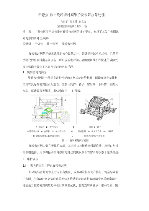
1 旋转密封阀简介旋转密封阀是一种具有密封性能的多格式旋转给料器,既能连续定量排料,又具有良好的密封性及耐磨性,主要由阀体、转子、密封副、下料槽、机架及台车、驱动装置等组成,其结构如图 1所示。
1-干熄炉 2-吹扫风机 6-阀体 7-转子3-旋转密封阀 4-皮带机 5-振动给料器 8-驱动装置 9-机架及台车 10-下料槽(a)旋转密封阀安装位置示意图 b)旋转密封阀结构示意图图 1 旋转密封阀示意图旋转密封阀安装在干熄炉底部,其进料口与振动给料器连接、出料口与排焦溜槽连接,用以将振动给料器给定排出的焦炭在相对密闭的状态下连续排出。
2 维护要点2.1 无负荷启动/停止旋转密封阀如果旋转密封阀停止时内部有焦炭,或振动给料器仍在排焦,均会导致转子卡阻,在启动时则会造成由单侧链条传动的旋转密封阀轴端受到单侧牵动力,特别是当旋转密封阀故障停机后的频繁试机,将对旋转阀轴承、驱动电机、链条都有相当大损害,所以应尽可能空载启动和停止旋转密封阀。
手动排焦时应先开启旋转密封阀,空转后再开启振动给料器,停止时应先停振动给料器,待无下料声音后再停旋转密封阀。
2.2 确保辅助密封气体压力正常为防止焦粉进入阀体两侧的轴承箱,在转子及阀体部位设有软硬密封机构,使承料部位与轴承箱间形成隔离空腔,并向隔离空腔通入辅助密封气体进行吹扫和冷却。
密封副位置由自动给脂装置定时、定量给脂,以保证润滑密封,同时保证辅助密封气体压力高于排出密封旋转阀内部气体压力,以防含尘气体进入阀体两侧密封腔。
阀门使用说明书

阀门使用说明书阀门是一种用于控制流体流动的装置,广泛应用于工业、建筑、农业等领域。
本使用说明书旨在帮助用户正确安装、操作和维护阀门,以确保其正常运行和延长使用寿命。
1. 产品概述阀门是一种控制流体流动的装置,常用于开启、关闭和调节管道中的液体或气体的流动。
根据不同的应用场景和工作原理,阀门可以分为多种类型,如球阀、闸阀、蝶阀等。
在本说明书中,我们将重点介绍球阀的使用方法。
2. 安装指南2.1 确保选择合适的阀门类型和规格,根据工作场景和流体性质选择球阀;2.2 在安装之前,必须检查阀门的外观是否完好无损,并检查阀体是否有防腐蚀涂层;2.3 根据管道规格和球阀的连接方式,选择合适的法兰或螺纹连接;2.4 安装球阀时,应先将法兰或螺纹连接加固好,确保不会漏气或漏液;2.5 安装完成后,应进行压力测试,确保球阀的密封性能正常。
3. 使用说明3.1 打开和关闭阀门:- 打开阀门:顺时针旋转阀门手柄或螺帽,使阀门处于完全打开的状态;- 关闭阀门:逆时针旋转阀门手柄或螺帽,使阀门处于完全关闭的状态。
3.2 调节流量:- 通过旋转阀门手柄或螺帽,可调节阀门开口大小,从而控制流体的流量;- 注意:请在检查阀门的额定压力范围内进行调节,避免损坏阀门或导致事故发生。
3.3 注意事项:- 阀门在操作前应检查密封性能,确保无泄漏现象;- 阀门在长时间闲置后,操作前应进行润滑保养,确保阀门灵活开闭;- 阀门在使用过程中如出现异常情况,应立即停止使用,并请专业人士进行检修。
4. 维护与保养4.1 定期检查阀门的密封性能和运行状态,确保阀门的正常工作;4.2 如发现阀门存在泄漏、生锈或其它损坏情况,应及时进行修理或更换;4.3 阀门需要定期润滑,以确保阀门的开闭灵活;4.4 在清洁阀门时,应使用中性清洁剂,并避免使用酸碱等腐蚀性物质。
5. 故障排除以下列举了一些可能发生的故障和排除方法:问题1:阀门漏水;解决方法:检查阀门密封垫片是否损坏,如有损坏应及时更换。
AT Controls 手动和自动旋转阀门文档说明书
9955 International Blvd. • Cincinnati, Ohio 45246 Phone: 513.247.5465 Fax: 513.247.5462Engineer: AMZ No.: DI00043Date Created: 07/09/2019 Date Modified: TSM ExtensionsTSM’s are designed for use with fugitive emissions to act as another form of packing on valve series that are already designed for fugitive emissions. When used manually the handles are lockable. TSM’s also allow for an extended mounting pad to which an actuator can be directly mounted. They can be added to the 22, 24, 33, 55, 77, T77, H78, 8R, 88, 90, D9 and F91 Series. See dimensional drawings P02774, P02776, T11580, and P02997 below.Spring Return HandlesSpring return handles are designed for manual operation and can spring open or close. Depending on the set up the valve will either spring open or closed when the handle is released. They are made up of a triangle pad and a handle. The spring is contained in the handle and is attached to the triangle pad, which can be seen in P03000 along with dimensions and applicable sizes. They can be added to the 22, 33, 77, 88/F88, F91, D9, FD9, 8R, F8R, 83/F83, and 90/F90 series. The F91, 8R / F8R, 83/F83 and 90/F90 series will additionally require a TSM for mounting purposes.Manual Valve with Limit SwitchLimit switches can be mounted to a manual valve using a coupler and a “C” shaped bracket.MATERIALDATECHECKED BY DESCRIPTION9955 INTERNATIONAL BLVD.CINCINNATI, OHIO 45246PHONE: (513) 247-5465FAX: (513) 247-5462DRAWN BY DATEAMZSpring Return Handle Dimensional Drawing07/09/19DO NOT SCALE DRAWINGRELEASED BY CMB07/09/19DATECMB07/09/19VALVES, ACTUATORS, AND AUTOMATION CONTROLS。
AT Controls 手动和自动旋转阀门产品说明说明书

Hydrogen Peroxide ServiceHydrogen Peroxide is a colorless liquid that can be used for things such as disinfection and bleaching. Handled correctly, Hydrogen Peroxide can be safe. Handled incorrectly, however, it can be explosive and dangerous.A very clean and safe system is required for Hydrogen Peroxide service because of the dangers of this molecule. With this in mind, careful selection of materials of construction and makeup of Hydrogen Peroxide service valves is imperative. It is also important to know whether the system will have diluted concentrations of Hydrogen Peroxide (less than 50%) or higher concentrations (greater than 50%), and the temperature of the application.Vented BallHydrogen Peroxide is prone to decomposition into water and oxygen. This decomposition can increase pressure, even sometimes rapidly, in the enclosed cavity of the valve. A table showing the amounts of these decomposition products is shown on the next page. A-T Controls provides a means of relieving this pressure by venting the ball in the upstream direction. This limits the valve to one direction flow and an arrow on the valve shows which direction the valve should be installed. A vented, upstream ball is required for Hydrogen Peroxide service.Preparation, Cleaning, and Lubrication Valves used for Hydrogen Peroxide service are required to be passivated according to ASTM A380/A380M and ASTM A967/A967M before going into service. A-T Controls valves meet these requirements. An inert lubricant such as a fluorinated product is required for the construction of the valves. A-T Controls thoroughly cleans all valve parts and lubricates the O-ring with a compatible lubricant. The valves are vacuum packed with desiccant and marked as cleaned for Hydrogen Peroxide Service. Standard MaterialPlease consult A-T Controls for material selection for your application. These parameters are guidelines, and customers are responsible for materials of construction and lubricants being compatible with their Hydrogen Peroxide application:Auxiliary Stem Seal: Viton®, Grafoil® (satisfactory for diluted)Body: ASTM A351 Grade CF8M (good for high concentrations), ASTM A351 Grade CF3MSeats: TFM™-1600, RTFE, PTFE, 50/50 STFE, EPDM (low concentrations)Trim: ASTM A351 Grade CF8M, 304 SSTValve PackagesSeries D9- Sizes ½”-6”, 150# and 300# ANSI, Full Port Design, ISO5211 Actuator Mounting Pad, Anti-Static Device, Traceable Valve.Literature Download & ContentSeries 88- Sizes ¼”-4”, Full Port, Direct Mounting Pad, Threaded, Socket Weld, or Butt Weld.Literature Download & ContentSeries 8R: Sizes ¼”-2-1/2”, High Performance 3-Piece Design, Regular, Stainless Body, Threaded, Socket Weld, or Butt Weld.Literature Download & Content。
旋转密封阀使用说明手册
精心整理济南信赢煤焦化有限公司150t/h干熄焦工程旋转密封阀使用说明书2006年7月12334444123.各机器的操作要领3.1旋转密封阀操作要领由振动给料器送出的焦碳从旋转密封阀上部的装入口投入,由于转子的转动,从下部的排精心整理出口被排出。
另外,如果固定了转子的转动数,焦碳的送出量的控制可以通过振动给料器来进行。
下面,关于旋转密封阀的各个构成部件的调整方法进行说明。
(1) 缓冲器的调整煤炭的大块混入焦碳中,在跟旋转密封阀咬住而停止时,为了保护本旋转密封阀,在装入口上部设计安装了缓冲器。
它有如下2个特征。
1)发生万一的时候,尽管煤炭、焦碳互相咬住,但如果是小块的,旋转密封阀可以压碎这些异物,这时候,没有必要停止机器,可以继续作业。
2)旋转密封阀咬住煤炭的大块的场合,缓冲器开始作用,吸收转子的转动能以及发动机(2子停止时,用缓冲器继电器可以进行检测出来,便于振动加料器以及旋转密封阀及时停止。
图7咬住异物转子停止时的检测方法缓冲器继电器的各种设定值如表6所示。
表2缓冲器继电器的各种设定值(参考值)4.1检查、维护排出装置的维护、检查项目以及进行的周期如表3所示。
另外,在图11、12里,显示了平面给料器外盒以及旋转密封阀的检查。
转子热膨胀图14热间膨胀时图15向密封环的拧紧力(2)密封环调整要领1)压盖密封、保护环的组合要领压盖密封、保护环的组合时,为了防止内漏和外漏,在结合部位和沟槽部位应填加硅系列密封材料(三合粘着剂1212#)。
另外,为了防止堆积灰尘,压盖密封、保护环的组合部位应位于转子叶片之间。
图16密封、保护环的组合2)密封环的组合要领事前,把油脂涂在密封环A、B上,(涂的时候,要求A面厚,B面薄)然后,在转子的侧面,再涂上为了防止积灰用的三合粘着剂(THREEBOND)1212#。
组合时,要求把密封环的结合部位位于转子叶片之间。
而且,为了使密封环的结合部位不至于和保护环的结合部位处于同一位置,请务必按照要求把密封环的结合部位位于转子叶片之间。
Belimo NFG-L 旋转安全气密控制阀说明书
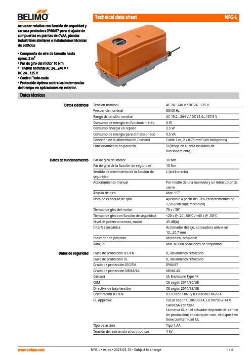
NFG-L Actuador rotativo con función de seguridad ycarcasa protectora IP66/67 para el ajuste decompuertas en plantas de CVAA, plantasindustriales similares e instalaciones técnicasde edificios• Compuerta de aire de tamaño hastaaprox. 2 m²• Par de giro del motor 10 Nm• Tensión nominal AC 24...240 V /DC 24...125 V• Control Todo-nada• Protección óptima contra las inclemenciasdel tiempo en aplicaciones en exterior.Datos técnicosDatos eléctricos Tensión nominal AC 24...240 V / DC 24...125 VFrecuencia nominal50/60 HzRango de tensión nominal AC 19.2...264 V / DC 21.6...137.5 VConsumo de energía en funcionamiento 6 WConsumo energía en reposo 2.5 WConsumo de energía para dimensionado9.5 VAConexión de la alimentación / control Cable 1 m, 2 x 0.75 mm² (sin halógenos)Funcionamiento en paralelo Si (tenga en cuenta los datos defuncionamiento)Datos de funcionamiento Par de giro del motor10 NmPar de giro de la función de seguridad10 NmL (antihorario)Sentido de movimiento de la función deseguridadAccionamiento manual Por medio de una manivela y un interruptor decierreÁngulo de giro Máx. 95°Nota de el ángulo de giro Ajustable a partir del 33% en incrementos de2,5% (con tope mecánico)Tiempo de giro del motor75 s / 90°Tiempo de giro con función de seguridad<20 s @ -20...50°C / <60 s @ -30°CNivel de potencia sonora, motor45 dB(A)Interfaz mecánica Accionador del eje, abrazadera universal12...26.7 mmIndicador de posición Mecánico, acoplableVida útil Mín. 60 000 posiciones de seguridadDatos de seguridad Clase de protección IEC/EN II, aislamiento reforzadoClase de protección UL II, aislamiento reforzadoGrado de protección IEC/EN IP66/67Grado de protección NEMA/UL NEMA 4XCarcasa UL Enclosure Type 4XCEM CE según 2014/30/UEDirectiva de baja tensión CE según 2014/35/UECertificación IEC/EN IEC/EN 60730-1 y IEC/EN 60730-2-14UL Approval cULus según UL60730-1A, UL 60730-2-14 yCAN/CSA E60730-1La marca UL en el actuador depende del centrode producción; en cualquier caso, el dispositivotiene conformidad ULTipo de acción Tipo 1.AATensión de resistencia a los impulsos4 kVNFG-L••••••••••••••Campo de aplicaciónModo de funcionamientoMontaje directo y sencilloDatos de seguridadGrado de polución 4Humedad ambiente Máx. 100% RH Temperatura ambiente-30...50°C [-22...122°F]Temperatura de almacenamiento -40...80°C [-40...176°F]Mantenimientosin mantenimiento PesoPeso 4.2 kgNotas de seguridadEste dispositivo ha sido diseñado para su uso en sistemas estacionarios de calefacción,ventilación y aire acondicionado y no se debe utilizar fuera del campo específico de aplicación, especialmente en aviones o en cualquier otro tipo de transporte aéreo.Precaución: alimentaciónSólo especialistas autorizados deben realizar la instalación. Durante la instalación, deberán cumplirse todas las regulaciones de instalación legales o institucionales que s cajas de conexiones deberán ser equivalentes como mínimo con el grado de protección IP de la carcasa.La carcasa protectora se puede abrir para realizar ajustes y el mantenimiento. Cuando se cierre más adelante, la carcasa deberá presentar un cierre estanco (véanse las instrucciones de instalación).El dispositivo sólo se puede abrir en el centro del fabricante. No contiene piezas que el usuario pueda reemplazar o reparar.No se deberán extraer los cables del dispositivo instalado en el interior.Para calcular el par de giro necesario, deberán respetarse las especificaciones facilitadas por el fabricante de la compuerta en lo relativo a la sección transversal, el diseño, el lugar de instalación y las condiciones de ventilación.El dispositivo contiene componentes eléctricos y electrónicos y no se puede desechar con los residuos domésticos. Deben tenerse en cuenta todas las normas y requerimientos locales vigentes.La unidad no ha sido diseñada para aplicaciones en las existan influencias químicas (gases, líquidos) ni para su uso en entornos corrosivos en general.El actuador no se puede utilizar en aplicaciones integrales (p. ej., falsos techos o falsos suelos).Los materiales utilizados pueden estar expuestos a influencias externas (temperatura, presión, fijaciones de construcción, efecto de las sustancias químicas, etc.) que no pueden simularse en las pruebas de laboratorio o en ensayos de campo. En caso de duda, lerecomendamos que haga una prueba. Esta información no implica ningún derecho legal. Belimo no se hará responsable ni ofrecerá ninguna garantía.En las aplicaciones UL (NEMA) Type 4X es necesario utilizar conductos para cables metálicos flexibles o conductos para cables roscados con el mismo valor.Cuando se utiliza con cargas UV elevadas, p. ej., en condiciones de luz solar extremas, se recomienda utilizar conductos de cables metálicos flexibles u otros equivalentes.Características del productoEl actuador está especialmente indicado para utilizarse en aplicaciones de exterior y cuenta con protección para las siguientes condiciones climáticas:- Radiación UV - Lluvia/nieve - Polvo/suciedad - HumedadEl actuador está equipado con un módulo de alimentación universal que puede emplear tensiones de alimentación de AC 24...240 V y DC 24...125V.El actuador mueve la compuerta hasta la posición de funcionamiento al mismo tiempo que tensa el muelle de retorno. Cuando se interrumpe la alimentación, la fuerza del muelle hace girar de nuevo la compuerta hasta la posición de seguridad.Montaje directo y sencillo en el eje de la compuerta con una abrazadera universal, suministrada con un dispositivo antirrotación para impedir que el actuador gire.NFG-LAccionamiento manualÁngulo de giro ajustable Alta fiabilidad funcionalSeñalización flexibleColores de los hilos:1 = azul 2 = marrónAl utilizar la manivela, se puede accionar la compuerta de forma manual y fijar con elconmutador de bloqueo en cualquier posición. El desbloqueo se lleva a cabo de forma manual o automática aplicando tensión.Para el accionamiento manual deberá retirarse la carcasa.Ángulo de giro ajustable mediante topes mecánicos.El actuador se encuentra protegido contra sobrecargas, no necesita ningún contacto limitador y se detiene automáticamente cuando alcanza el final de carrera.Si se requiere una combinación con los siguientes accesorios eléctricos, póngase en contacto con su representante de Belimo.Contacto auxiliar 2 x SPDT S2A-FPotenciómetro de realimentación 200 Ω P200A-F Potenciómetro de realimentación 1 kΩ P1000A-FAccesoriosAccesorios mecánicosDescripciónModelo Prensaestopas para diámetro de cable ø4...10 mmZ-KB-PG11Instalación eléctricaPrecaución: alimentaciónEs posible realizar una conexión en paralelo de otros actuadores. Respete los datos de funcionamiento.Esquema de conexionadoAC 24...240 V / DC 24...125 V, todo-nadaNFG-L DimensionesLongitud del eje-16...105 (ø12...19)16...45 (ø19...26.7)Rango de nuez。
旋转阀说明书

耐磨陶瓷旋转进料阀说明书
本阀主要适用于火电厂干灰系统灰、渣出料的启闭之用,也适用于矿山、石灰厂、水泥厂等有磨损、腐蚀的粉尘介质的出料启闭。
本阀门具有密封性能好,耐高温,耐磨性强,启闭灵活,无卡灰及积灰现象,使用寿命长等特点。
*耐磨陶瓷转出料阀产品主体采用铸钢、铸铁、耐磨陶瓷组合而成。
*使用温度0-400°C
*执行机构公称压力为0.4-0.6Mpa,阀门公称压力为1Mpa。
出料阀的安装说明:
欢迎您选用本公司专利产品。
为了延长使用寿命,提高工作效益,本阀门在安装时尽量做到直立安装。
在条件不允许的情况下要45度装。
如倒装或水平装的情况下,必须延长空送时间,避免阀体积灰。
本阀门返回迅号采用进口电感磁性开关二线制,通过负载本迅号线可适应直流,交流均可。
“安装迅号见图”
安装、使用要点
1、安装前应仔细阅读本说明、并核对阀门型号、通径及技术参数。
2、严禁装上阀门后施焊法兰,以免损坏阀门密封圈。
管道自先预留的阀门安装距离应适当,法兰两边加垫片。
3、两管道中心与阀门通径中心应保持同轴,法兰面应平整,不允许法兰面有较大的偏斜,以保证阀门的夹紧和正常工作。
拧紧螺栓应做到均匀对称。
阀板旋转型止回阀操作与维护说明-510型 带有层状密封说明书

阀板旋转型止回阀操作与维护说明510型带有层状密封Tiltin g Disc Type Check Valves目录1. 介绍 (2)2. 使用目的 (2)3.安全说明 (2)3.1.安全说明概述 (2)3.2.操作者的安全说明 (2)3.3.特殊危险 (3)4.阀板旋转型止回阀的铭牌 (4)5.运输和存储 (4)6.管道中的安装 (5)6.1.概述 (5)6.2.安装准备 (5)6.3. 安装位置和流向 (6)6.4.安装步骤 (6)7. 压力测试和试车 (7)8. 正规操作和维护 (7)9. 故障诊断指南 (8)10.图纸 (9)10.1.零件明细表 (9)10.2.细部图>阀板旋转型止回阀<带法兰 (10)10.3. 细部图>阀板旋转型止回阀<带焊接头 (11)11.维修说明 (12)11.1.概述 (12)11.2. 更换轴承盖垫圈 (12)11.3.更换轴密封 (12)11.4 更换层密封 (13)Tiltin g Disc Type Check Valves1. 介绍这个手册的目的是帮助用户安装、操作和维修阀板旋转型止回阀。
危险!如果不遵从下面的注意事项和警告,会导致危险。
制造商对此不负有责任。
出现任何问题请联系克隆巴赫。
2. 使用目的在阀板旋转型止回阀被安装到管道系统(通过法兰或焊接连接)和电机(如果是定购的)被连接到控制系统后,止回阀让介质沿流向方向通过,防止回流。
阀板旋转型止回阀原则上是自动阀。
油压闸阻尼关闭或者关闭和打开(根据用户的需求)。
附加的执行机构被安装为了专用功能(与定购有关),例如自动关闭,自动打开等。
⇒ 允许通过的介质包含的固体物质不能多于说允许的的一个非常小的比例。
⇒ 不推荐在带有腐蚀作用的介质中使用阀板旋转型止回阀。
⇒ 最大可允许压力和最大可允许温度表示在阀门的型牌上。
⇒ 如果介质有堆积内部沉淀物的趋势,阀板旋转型止回阀不应该被使用。
干熄焦旋转密封阀

能指 标 ,并就其应用和 发展进行 了 探讨 。 【 关键词不好 ,尤其是使用一
段时间后 ,密封性越 来越 差 ,大量焦粉外溢 ,环境 中一
干 熄焦
结构 性 能指
氧化碳超标 ,严重污染环境 ,危害工作人员 健康。经过
对排出装置进行改造 ,选用了旋 转密封阀 ,彻底解决了
中使用的是两层闸板阀方式,排焦时先将第一道闸板打
开 ,焦炭落人两层闸板之 间,然后关闭第一道闸板 ,打 } 的转速可适应不同料流量。为减少干熄炉内气体介质外 开第二道闸板将焦炭排放 。 这种排 焦方式的缺点是 : f 漏 ,需控制转子 刃与机体 内壁的 间隙 ,间隙越小 ,干熄
粉尘的外泄,稳定干熄炉内循环气体的压力, 是现代先 . 连续定量排焦并同时将系统内外分隔,稳定干熄炉系统
进干熄焦工艺必选的关键设备。 在 宝钢 一期及 浦东 煤气 厂的传 统干 熄焦排 出装 置
压 力。
旋 转密封 阀工作原理如 图2 所示 ,旋转过 程中 ,焦 炭经各隔仓 由上至下均匀排 出,调整料仓的大小及转子
损。并在阀体两侧轴承箱内通入高于干熄焦塔内压力的 氮气或空气辅助密封,使干熄炉内高温 ( 约2 0 0  ̄ C)含
尘 气体不能进入轴承 箱 ,改善 了轴承和密封环的 工作 环
境,能够有效地防止轴承温升超高,减少密封环磨损。
图4 直连式旋转密封阀
2 0 1 3  ̄ 第1 期
第 期 w w w .. e t y 1 { 6 V 3 V
图3 密封副示意
为满足连续密闭排焦功能,干熄焦旋转密封阀转 子内部为l 2 个叶片,转子两端支撑在阀体轴承箱内,为 防止焦粉进入轴承箱,转子及阀体相应部位设置软硬密 封机构,形成承料部位与轴承箱隔离空腔,并在此部位
Parker Hannifin 螺旋式旋转机械腿式气动阀门说明书

PV SeriesPneumatic Vane Rotary Actuators ContentsFeatures .............................................................................H6 Ordering Information...........................................................H7 Specifications .....................................................................H8 Engineering Data ................................................................H9Dimensions .......................................................................H10 Options .....................................................................H11-H14 Sensors ............................................................................H14 Service Kits ......................................................................H15A076 PV SeriesHeadsSolid stock heads are precisionmachined from aluminum,then hard-coat anodized andpermanently sealed to ensurelong seal life and low breakawaypressure. Solid stock headseliminate cavities wherecontaminants may collect and alsoallow rear porting.Vane SealA special self-lubricated, abrasionresistant nitrile compound ismolded into a one-piece vaneseal, providing low breakawaypressure and long life, even withno lubrication.VaneA hard-coat anodized,precision aluminumextrusion is permanentlyaffixed to shaft. Thelightweight vane reducesinertia allowing very fastrotational speeds.BodyThe precision body extrusion ishard-coat anodized and permanentlysealed, resulting in a smooth, slick sealsurface. This guarantees minimumbreakaway and maximum seal life.The unitized body incorporates thestator(s) for superior rigidity.Shaft BearingThermoplastic journal bearingprovides washdown capabilityand low cost. Optional radialball bushing offers greaterprecision.ShaftStainless steel provideshigh strength and corrosionresistance for demandingapplications. FeaturesShoulder SealA nitrile energized, glass-filled T eflon® seal is utilized. Itreduces bypass flow and friction,providing superior performanceand long life.Shaft SealThe high quality, self-lubricated, abrasion resistantnitrile seal is a multiplelobe construction for leak-free operation and greaterreliability.(Cleanroom option availableon sizes 22, 42, 44 and 46.)PV SeriesA076Ordering InformationModel Code and Ordering InformationExample: PV22D - 090BS - BB2V - BSpecial Options Omit - (STD)T wo digit code assigned by factory when any "X" appears in the model number or when special options or features are required.Rotation Options (may order more than one)Omit Standard Units (no stroke adjusters, bumpers or switches)090A Stroke Adjusters adjustable from 60° to maximum unit rotation (preadjusted to 90°)180A Stroke Adjusters (single vane only) adjustable from 60° to 190° ( preadjusted to 180°)090B Internal bumpers , 90° rotation 4180B Internal bumpers, 180° rotation (single vane only)090S Magnets 1 added, 90° setting180S Magnets 1 added, 180° setting (single vane only)MountingB Base / Front (Std)R Rear Flange 2, 3F Front FlangeSBase / Rear Face 2Vanes / Maximum Rotation Omit Single Vane, 280° Rotation (275° on PV10, PV11)D Double Vane, 100° Rotation(95° on PV10, PV11)Model10 22 33 4211 36 4446Design Series B Current Design SeriesShaftB Single Male Keyed (Std)C Double End Male Keyed 2Ports2 NPTF Top (Std)(10-32 on PV10 & PV11) 7 NPTF Rear 2(10-32 on PV10 & PV11)OptionsOmit - NoneL Radial Ball Bushings V Fluorocarbon Seals 1. Switches can be used with stroke adjusters or bumpers (example: PV22D-090BS-BB2-B).2. Not available with switches or stroke adjusters.3. No tapped mounting holes in face opposite the flange.4. 90° bumpers (090B) not available on PV10/11 sizes.Note:Order Hall effect sensors and reed switches separately from the Electronic Sensors section.PV 22D 090BS B B ––2V B–A076PV SeriesSpecifications * See Fluorocarbon seal option for high temperature applications.† For low temperature version, please consult factory.Specifications• Maximum operating pressure: 150 psi air • Output torque @ 100 psi: 8 to 1800 lb-in• Standard rotations: Single vane units: 280° ± 1° (except size 10 & 11: 275° ± 2.5°) Double vane units: 100° ± 1° (except size 10 & 11: 95° ± 2.5°) Also available with stroke adjusters and internal stops to provide 90° and 180° rotation• Maximum breakaway pressure and bypass leakage: see table • Mounting orientation: unrestricted• Operating temperature range †: Nitrile seals 30 to 180°F Fluorocarbon seals* 30 to 250°F •Filtration requirement: 40 micron filtered, dry airQuick Reference DataModel Maximum Rotation (Deg)Actual Output Torque (lb-in)at Specified Input Pressure (PSI)Displacement(in 3)Maximum Breakaway Pressure (PSI)Maximum Bypass Leakage @100 PSI(cfm)Unit Weight (lb)5075100102754680.52250.150.3810D 95812160.37200.200.381127581216 1.04200.150.5011D 951725330.74150.200.5022280324864 3.67150.200.5022D 10068101135 2.62100.25 1.7533280751121508.70150.20 3.4433D100155235315 6.20100.25 3.563628015022030017.40150.20 5.1936D 10031547063012.40100.25 5.50 4228014021028517.80150.207.1342D 10030045060014.58100.257.504428028542557035.61150.208.8144D 100600900120029.17100.259.384628042564085053.41150.2010.5046D1009001350180043.75100.2510.75Kinetic Energy Ratings and Bearing Load CapacitiesModel Composite Bushing Load Capacities (lb)*Radial Ball Bushing Load Capacities (lb)*Distance Between Centerline BearingsMaximum Kinetic Energy Rating for ModelsBased on Configuration (in-lb)Radial Thrust Radial Thrust Standard Stroke AdjustersBumpers 10 15 750150.880.030.120.0511 15 750151.500.060.120.0922 50 25Consult Factory2.380.250.500.3833100 50Consult Factory3.500.75 1.50 1.1336100 50Consult Factory 6.50 1.00 1.50 1.504220075Consult Factory 2.75 2.004.00 3.004420075Consult Factory 4.75 2.50 4.00 3.754620075Consult Factory6.753.004.004.75* Bearing capacities only. Check Kinetic Energyratings to determine if actuator will stop load.Radial LoadPV SeriesA076bacbabakkLkkW 1W2W 1aW 2Engineering DataSOLID SPHERE -Mounted on centerTHIN DISK-End mounted on centerPOINT LOADTHIN RECTANGULAR PLATE -Mounted on centerTHIN RECTANGULAR PLATE -Mounted off centerTHIN DISK-Mounted on centerJm = x+ x4a 2 + c 2W 2SLENDER ROD -Mounted off centerJm = xa 2 +b 2THIN RECTANGULAR PLATE-End mounted on centerWg 2k 2Jm = xWg 4k 2Jm = x5 gW Jm = x x k 2W gJm = x k 22Moments of InertiaKinetic Energy Basic FormulaKE = 1/2 Jm ω2 ω = 0.035 xAngle Traveled (Deg.)Rotation Time (Sec.)where:KE = Kinetic Energy (in-lb)Jm = Rotational mass moment of inertia (in-lb-sec 2) (Dependent on physical size of object and weight)ω = Peak Velocity (rad/sec) (Assuming twice average velocity)W = Weight of load (lb)g = Gravitational constant = 386.4 in/sec 2k = Radius of gyration (in)WW 14b 2 + c 2 g 12 Jm = xL 2W Wa 2 Jm = xg 12 W 1 a 2 W 2 b 2Jm = x + xg 3 g 3SLENDER ROD-Mounted on center g12 g 12g 12A076Standard Face/Base Mount (B) and Male Keyed Shaft (B)Model A B C D E F G H I J K L M N O P R10 2.280 1.380.880.3120.3110.2580.2530.0940.0950.630.19 1.000.19 1.000 1.620.810 1.2200.75010-328-32 x0.25 DP11 2.905 2.000.880.3120.3110.2580.2530.0940.0950.630.19 1.630.19 1.625 1.620.810 1.2200.75010-328-32 x0.25 DP22 4.340 3.06 1.250.5000.4990.4230.4180.1250.1260.940.25 2.560.25 2.560 2.50 1.250 2.000 1.2501/8 NPTF1/4-20NC x0.38 DP33 6.180 4.40 1.750.7490.7480.6440.6390.1880.1891.380.35 3.700.26 3.875 3.00 1.5002.436 1.5001/4 NPTF5/16-18NC x0.47 DP369.1807.40 1.750.7490.7480.6440.6390.1880.1891.380.35 6.700.26 6.875 3.00 1.5002.436 1.5001/4 NPTF5/16-18NC x0.47 DP42 6.280 4.00 2.250.9990.9980.8590.8540.2500.2512.000.503.000.50 3.0004.50 2.250 3.500 2.3751/4 NPTF3/8-16NC x0.75 DP448.280 6.00 2.250.9990.9980.8590.8540.2500.2512.000.50 5.000.50 5.000 4.50 2.2503.500 2.3751/4 NPTF3/8-16NC x0.75 DP4610.2808.00 2.250.9990.9980.8590.8540.2500.2512.000.507.000.507.000 4.50 2.2503.5002.3751/4 NPTF 3/8-16NC x 0.75 DPA076Flange Mount (F, R)*Double End Male Keyed Shaft (C)Note: The face opposite the flange mount does not contain tapped mounting holes. Consult factory if needed.Model A B C D E F G H 10 2.50 1.62 2.000 1.2500.2030.190.41N/A 11 2.50 1.62 2.000 1.2500.2030.190.41N/A 22 3.50 2.50 3.000 2.0000.2810.250.66 2.87533 4.50 3.00 3.750 2.0000.3440.380.84N/A 36 4.50 3.00 3.750 2.0000.3440.380.84N/A 427.32 4.51 5.905 2.9530.5510.63 1.61N/A 447.32 4.51 5.905 2.9530.5510.63 1.61N/A 467.324.515.905 2.9530.5510.631.61N/AModelA B C D E F 10 2.750.880.500.3120.3110.28#302.5113.380.880.500.3120.3110.28#302.522 5.06 1.250.750.5000.4990.44#404337.15 1.75 1.000.7490.7480.56#6063610.15 1.75 1.000.7490.7480.56#606427.53 2.25 1.280.9990.9980.72#808449.53 2.25 1.280.9990.9980.72#8084611.532.251.280.9990.9980.72#808Note: Not available with switches or stroke adjustment.Consult factory for rear port option.A076Adjustable Rotation Stop (090A, 180A)An adjustable positive stop is available to provide end of rotation adjustability in a compact package. T otal adjustment range is 60° to 190° on single vane ac-tuators, and 60° to 100° on double vane actuators (95° on PV10/11 sizes). The rotation is factory preset to a nominal 90° or 180° (090A or 180A) for convenient installation.NOTE: 1. Not available with double end shaft. 2. Not available with rear ports.Model A B C D E F 10 1.620.630.470.240.753/3211 1.620.630.470.240.753/3222 2.50 1.000.720.36 1.255/3233 3.00 1.160.970.48 1.563/1636 3.00 1.160.970.48 1.563/1642 4.50 1.38 1.250.56 2.257/3244 4.50 1.38 1.250.56 2.257/32464.501.381.250.562.257/32SINGLE VANE UNITDOUBLE VANE UNITPV10/PV11D SIZES)ROTATIONA07690° or 180° Bumpers (090B, 180B)Bumpers are available to reduce noise and dissipate energy. This permits faster cycle times and increased production rates. Single vane units are available with 90° or 180° bumpers and double vane units are available with 90° bumpers.90° or 180° Magnet (S)Option "S" provides a magnet(s) attached to the actuatorshaft. Hall effect or reed switches sense the position of these magnets. The switches are available in two nominal rotations, 90° or 180°, and the adjustment is ±20° for each switch to provide a total adjustment of ±40°. Adjustable stops, "A", or bumpers, "B", can be supplied in addition to magnets. Order switches separately.Example Ordering Codes, Keyway Positionsand Switch Sensing Locations:Please note the following keyway position and switch sensing locations, with respect to ordering codes and options, with porting at the 12:00 position as viewed from the output shaft end (as shipped from the factory).180S,180AS, 180BS - Single vane actuator with magnet or with magnet and stroke adjusters and/or bumpers: Keyway midstroke position at 6:00, magnet positioned to sense at 3:00 and 9:00.090S, 090AS - Single vane actuator with magnet or with magnet and stroke adjusters: Keyway midstroke position at 6:00, magnet positioned to sense at 4:30 and 7:30.090S, 090AS, 090BS - Double vane actuator with magnet or with magnet and stroke adjusters or bumpers; or single vane actuator with magnet and bumpers: Keyway midstroke position at 9:00, magnet positioned to sense at 7:30 and 10:30.90° BUMPERS (090B)180° BUMPERS (180B)180(+5° -0°)CENTER OF ROTATIONA076PV SeriesSolid State (Hall Effect) and Reed SensorsSensors are available in a normally open or normally closed configuration. The low amp reed sensor is suitable for connection to PLCs or other low current devices. The high amp sensor can be used to drive sequencers, relays, coils or other devices directly.Sensors must be ordered separately from the Electronic Sensors section.Rear Port (7)Rear porting provides convenience for confined mounting on very small units being face mounted.This option is not available with switches or strokeadjustment. Consult factory for double end shaft option.*Consult factory for higher temperature operation.Model A B C 100.540.5010-32110.540.5010-32220.880.751/8 NPTF 33 1.090.901/8 NPTF 36 1.090.901/8 NPTF 42 1.68 1.001/4 NPTF 44 1.68 1.001/4 NPTF 461.681.001/4 NPTFOption Temperature Range* (°F)Bumpers 0 - 200Magnets 0 - 155Switches14 - 185Bearings - Radial Ball Bushings (L)Composite bushings should be used for washdown, highly contaminated, and low priced applications. Radial ball bushings provide greater precision. For bearing loadcapacities, reference the Engineering Data section of the catalog.Consult factory for pricing and availability.Fluorocarbon Seals (V)Standard self-lubricating, abrasion resistant nitrile seals should be used for general purpose applications with temperatures of 0 to 180°F . Fluorocarbon seals arerecommended for high temperature applications up to 250°F .Radial Ball BushingComposite BushingOptions & Sensors "C" PORTSABB/260" Cord6" Cord 1 Brown4 Black 3 BluePV SeriesA076Service KitsVPV22DPSKModel NumberParker Seal Kit Omit = Nitrile V = FluorocarbonSeal Kit Ordering InformationModel (S)Items Seal Guide KitNumber PV10 &11 (D)21, 22A TS-PV1PV22 (D)21, 22A TS-PV2PV33 & 36 (D)21, 22A TS-PV3Seal Kit Installation ToolPV SeriesNotesA076。
气动旋转园盘阀安装使用说明书

气动旋转园盘阀安装使用说明书The instruction for pneumatic revolving disc valve’s Installation andusing一、安装、使用和维护要点Installation, using and maintenance1、安装前应仔细阅读本说明书,核对阀门型号、通径及相关技术参数,检查气动执行机构外观有无破损等缺陷。
We should read this instruction carefully before the installation, and check the valve model,diameter, the related technical parameter, whether there is damages outward pneumatic appearance.2、严禁装上阀门后施焊法兰。
法兰两边加石棉垫片。
Forbid welding theflange after installing the valve. Both sides of the flange should be added the asbestos gasket.3、两管道中心与阀门中心应保持同轴,不允许法兰面有较大的偏斜,以保证阀门的夹紧和正常工作。
拧紧螺栓应做到均匀对称。
Two pipeline’scenters and the valve’s center should maintain coaxial. Does not allow the big deflexion in the flange surface to guarantee the valve well and the normal work. Screwing down the bolt to be symmetry.4、不要用硬物触碰阀板,现场安装前用气驱动一下气缸,使阀处于打开位置,这样可防止安装时不小心碰上阀板。
旋转阀安全操作及保养规程
旋转阀安全操作及保养规程1. 前言旋转阀是一种常用的控制元件,广泛应用于工业和民用领域。
对于旋转阀的安全操作及保养,不仅涉及设备运行稳定性和延长使用寿命,还涉及工作人员的人身安全和环境保护等问题。
本文主要介绍旋转阀的安全操作及保养规程,旨在帮助工作人员规范使用和保养旋转阀,确保设备安全可靠地运行。
2. 安全操作规程2.1 操作前准备在操作旋转阀前,必须进行以下准备工作:•检查旋转阀的安装位置是否正确,是否与管道接口连接松动或泄漏。
•检查旋转阀的电气设备和控制系统是否正常运行。
•检查旋转阀的密封性能是否良好。
•根据工况要求设置好旋转阀的开度和停机位置。
2.2 操作流程在操作旋转阀时,应按以下步骤操作:1.开启旋转阀控制设备,启动旋转阀。
2.根据需要调整旋转阀的开度,控制介质的流量。
3.监测旋转阀的运行状态,包括旋转阀的开度、温度、压力等参数。
4.停机前必须将旋转阀关闭,并检查旋转阀的密封性和旋转部件运转情况。
2.3 安全措施在操作旋转阀时,应注意以下安全措施:•在操作旋转阀前,必须检查控制系统的互锁装置是否有效,并确保旋转阀无误操作的风险。
•操作人员要熟悉旋转阀的结构、性能、工作原理等,并严格按照工艺要求进行操作。
•操作人员必须严格遵守安全操作规程,禁止私自更改设备参数或超负荷运行设备。
•如发现旋转阀有泄漏或其他异常情况,应立即停车并通知相关人员处理。
•对于较大的旋转阀操作,应有足够的工作人员和保护措施,以确保安全。
3. 保养规程对于旋转阀的保养需定期进行,以保持设备的良好状态和性能。
以下是旋转阀的保养规程:3.1 保养周期旋转阀的保养周期应按照以下标准制定:•年保养:主要针对旋转阀的设备框架、结构件、密封部位、传动机构、接口结构等进行清洁、润滑及检测等,重点是检查旋转阀是否损坏或受损。
•季度保养:主要针对旋转阀的传动机构、密封结构、控制机构、支撑结构等进行检查、清洁、润滑、观察等,重点是检查旋转阀的密封性是否良好、传动部件是否磨损等。
干熄焦旋转密封阀启停标准化流程

干熄焦旋转密封阀启停标准化流程下载温馨提示:该文档是我店铺精心编制而成,希望大家下载以后,能够帮助大家解决实际的问题。
文档下载后可定制随意修改,请根据实际需要进行相应的调整和使用,谢谢!并且,本店铺为大家提供各种各样类型的实用资料,如教育随笔、日记赏析、句子摘抄、古诗大全、经典美文、话题作文、工作总结、词语解析、文案摘录、其他资料等等,如想了解不同资料格式和写法,敬请关注!Download tips: This document is carefully compiled by theeditor. I hope that after you download them,they can help yousolve practical problems. The document can be customized andmodified after downloading,please adjust and use it according toactual needs, thank you!In addition, our shop provides you with various types ofpractical materials,such as educational essays, diaryappreciation,sentence excerpts,ancient poems,classic articles,topic composition,work summary,word parsing,copy excerpts,other materials and so on,want to know different data formats andwriting methods,please pay attention!一、干熄焦旋转密封阀启动标准化流程1. 启动前的检查检查旋转密封阀的驱动装置是否正常,如电机、减速机等。
旋塞阀使用说明范文
旋塞阀使用说明范文一、旋塞阀的原理和结构旋塞阀是一种常用的工业管道阀门,通过旋转阀门内部的旋塞体,来实现对流体的控制。
旋塞阀的结构由阀体、旋塞体、阀杆和传动装置等组成。
1.阀体:旋塞阀的阀体通常采用铸铁、碳钢、不锈钢等材质制作,具有强度高、耐腐蚀性好等特点。
2.旋塞体:旋塞体是控制介质流动的重要组成部分,通常是一个锥形或球形的结构,其形状决定了阀门的流量特性。
3.阀杆:阀杆用于传递外部操作力到旋塞体上,使其旋转以控制介质的流量。
阀杆通常与阀门通过螺纹连接,并通过填料或密封结构确保密封性。
4.传动装置:如果需要手动操作阀门,通常会使用手柄、蜗轮蜗杆机构等传动装置,使操作更加方便。
二、旋塞阀的使用注意事项在使用旋塞阀之前,需要注意以下几个方面:1.安装位置:旋塞阀应安装在垂直管道上,以保证阀门能够正常工作。
如果需要在水平管道上安装旋塞阀,需要采取额外的支撑和固定措施。
2.温度和压力:在选择旋塞阀时,要考虑介质的温度和压力,选择适合的阀体和密封材质,以确保阀门在工作条件下能够正常密封。
3.操作方式:旋塞阀可以手动或自动操作。
手动操作时,需要通过手柄或传动装置来控制旋塞体的旋转。
自动操作时,可以通过气动或电动装置来控制阀门的开闭。
4.泄漏检测:在使用旋塞阀之前,应进行泄漏检测,以确保阀门在关闭状态下能够完全密封。
可以通过检查阀门的泄漏等级和密封性能来判断阀门的质量。
三、旋塞阀的操作步骤1.手动操作:(1)将手柄或传动装置与阀杆连接。
(2)根据需要,将手柄或传动装置固定在合适的位置。
(3)将阀门旋转到所需位置,控制介质的流量。
2.自动操作:(1)将气动装置或电动装置与旋塞阀连接。
(2)根据需要,通过控制器或遥控装置来控制阀门的开闭。
(3)根据阀门的工作条件,设置开启和关闭的时间和角度。
四、旋塞阀的维护保养1.定期检查:定期检查旋塞阀的密封性能、传动装置的灵活性和阀杆的磨损情况,及时发现问题并进行维修。
2.清洁保养:定期清洗旋塞阀内部的污物和堵塞物,确保阀门的畅通性。
TY641耐磨陶瓷旋转阀说明书
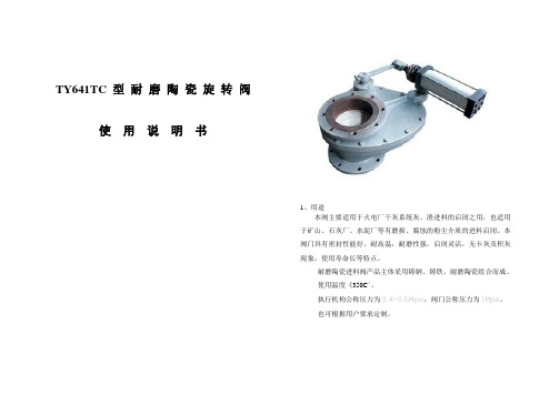
使用说明书1、用途本阀主要适用于火电厂干灰系统灰、渣进料的启闭之用,也适用于矿山、石灰厂、水泥厂等有磨损、腐蚀的粉尘介质的进料启闭。
本阀门具有密封性能好,耐高温,耐磨性强,启闭灵活,无卡灰及积灰现象,使用寿命长等特点。
耐磨陶瓷进料阀产品主体采用铸钢、铸铁、耐磨陶瓷组合而成。
使用温度《350C°。
执行机构公称压力为0.4~0.6Mpa,阀门公称压力为1Mpa。
也可根据用户要求定制。
2、耐磨陶瓷旋转阀名称图主要部件材质阀体:球铁或Q235 ;密封件:四氟或柔性石墨阀板:WCB+ZAT ;压盖和支架:WCB阀座:ZTA ;连接件:35CrMo3、耐磨陶瓷旋转阀外形尺寸、连接尺寸4、耐磨陶瓷旋转进料阀外形尺寸、连接尺寸以及执行器型号表通径(mm)连接尺寸DN D K d b Z─Фd L 150X150 285 240 210 18 8─Ф18 140 200X200 340 295 266 20 8─Ф22 300 250X250 395 350 320 24 12─Ф22 300 250X300 445 400 370 26 12─Ф22 280 250X400可替代进口圆顶阀620 560 470 25 12─Ф22 3005、耐磨陶瓷旋转阀安装说明欢迎您选用本公司专利产品。
为了延长使用寿命,提高工作效益,本阀门在安装时切勿碰坏气缸,水平安装在仓泵上即可。
本阀门返回迅号采用进口电感磁性开关二线制,通过负载本迅号线可适应直流,交流均可。
“安装迅号见图”6、可能发生故障的原因及消除方法故障现象原因分析排除方法气缸不能作动1.空气压力不够;2.电磁阀有故障;3.气缸缸筒是否损坏。
1.检查空气压力;2.检修或更换电磁阀;3.检查缸筒是否失圆,如损坏更换缸筒。
没返回信号1.信号线安装位置不准确;2.信号开关线路不对;3.信号线损毁。
1.信号线安装位置不准确;2.信号开关线路不对;3.信号线损毁。
阀关闭时出现泄漏1.阀体与执行机构连接处密封圈或气缸活塞杆已磨损;2.阀芯没有关闭到位,阀腔内壁有杂物卡住阀芯;3.阀芯或阀盖密封面已磨损。
阀门操作手册
阀门操作手册文件编号:标题: 阀门操作规程页码第1页共2页1.目的为使我公司的阀门能够规范进行操作,特制订本规程。
2.适用范围适用于公司的球阀(手动、电动)、旋塞阀、节流截止放空阀的操作。
3.职责3.1 运行保障部负责监督本规程的执行情况。
3.2 各分子公司遵照本规程进行相应的操作。
4.操作步骤4.1 球阀开启操作4.1.1手动球阀的开启4.1.1.1双手握住手轮按照阀门开关指示器上的方向指示(一般为逆时针方向)转动,同时应密切注意蜗轮-蜗杆传动装置的有无转动、有无异常声响。
4.1.1.2按照阀门上的开关指示确定开到位。
4.1.1.3开到位后手轮往回转一点,以保证轮齿啮合部分不再处于受力状态。
4.1.2电动球阀的开启4.1.2.1打开红色转换开关的锁定装置,将红色转换开关打到“”位置;4.1.2.2把手柄扳到手动位置;4.1.2.3按逆时针方向转动手轮,将阀门开到5%,待阀门前后压力平衡后,朝“”方向转动黑色开关,将阀门全开;4.1.2.4确认阀门全开后,把红色转换开关打到“”位置,将锁定装置锁好。
4.2 球阀关闭操作4.2.1手动球阀的关闭4.2.1.1按照开关指示器的方向旋转操作(柄)手轮;4.2.1.2按照开关指示确定开关到位。
4.2.1.3关到位后手轮往回转一点,以保证轮齿啮合部分不再处于受力状态。
4.2.2电动球阀关闭操作4.2.2.1打开红色转换开关的锁定装置,将转换开关打到“”位置;4.2.2.2朝“”方向转动黑色开关,开始关闭阀门;4.2.2.3确认阀门全关后,把红色转换开关打到“”位置,将锁定装置锁好。
4.3旋塞阀的操作4.3.1旋塞阀的开启文件编号:标题: 阀门操作规程页码第2页共2页4.3.1.1双手握住手轮按照阀门开关指示器上的方向指示(一般为逆时针方向)转动。
4.3.1.2 按照阀门上的开关指示确定开到位。
4.3.1.3开到位后手轮往回旋转半圈,以保证轮齿啮合部分不再处于受力状态。
- 1、下载文档前请自行甄别文档内容的完整性,平台不提供额外的编辑、内容补充、找答案等附加服务。
- 2、"仅部分预览"的文档,不可在线预览部分如存在完整性等问题,可反馈申请退款(可完整预览的文档不适用该条件!)。
- 3、如文档侵犯您的权益,请联系客服反馈,我们会尽快为您处理(人工客服工作时间:9:00-18:30)。
矿产资源开发利用方案编写内容要求及审查大纲
矿产资源开发利用方案编写内容要求及《矿产资源开发利用方案》审查大纲一、概述
㈠矿区位置、隶属关系和企业性质。
如为改扩建矿山, 应说明矿山现状、
特点及存在的主要问题。
㈡编制依据
(1简述项目前期工作进展情况及与有关方面对项目的意向性协议情况。
(2 列出开发利用方案编制所依据的主要基础性资料的名称。
如经储量管理部门认定的矿区地质勘探报告、选矿试验报告、加工利用试验报告、工程地质初评资料、矿区水文资料和供水资料等。
对改、扩建矿山应有生产实际资料, 如矿山总平面现状图、矿床开拓系统图、采场现状图和主要采选设备清单等。
二、矿产品需求现状和预测
㈠该矿产在国内需求情况和市场供应情况
1、矿产品现状及加工利用趋向。
2、国内近、远期的需求量及主要销向预测。
㈡产品价格分析
1、国内矿产品价格现状。
2、矿产品价格稳定性及变化趋势。
三、矿产资源概况
㈠矿区总体概况
1、矿区总体规划情况。
2、矿区矿产资源概况。
3、该设计与矿区总体开发的关系。
㈡该设计项目的资源概况
1、矿床地质及构造特征。
2、矿床开采技术条件及水文地质条件。
