基于JTAG接口实现ARM的FPGA在线配置.
基于Flash和JTAG接口的FPGA多配置系统

M e nw h l a ie,i a hiv st ei y t m o i r to i wic h o h t e s ra om m unc ton T h r c ia pl a i ho st tt s t c e e h n s s e c nfgu a in bts t h t r ug h e ilc ia i . e p a tc lap i tons w ha hi c s t m se s n ng,we lpe f r a c l w os nd ge r lpu p e ys e ha a y ha di l ro m n e,o c ta ne a r os .
i
譬
| ¨
噩 i
基 于 F a h和 J AG 接 口 的 F GA 多 配 置 系 统 ls T P
王 群 泽 。 方 明 , 汉 成 , 鑫 , 圣 陶 胡 林 熊 吴
( 安 电 子 科 技 大学 电子 工 程 学 院 , 安 7 0 7 ) 西 西 1 0 1
摘 要 :针 对 需 要 切 换 F GA 器 件 的 配 置 以 实 现 不 同 功 能 的 特 殊 应 用 场 合 , 出 了 一 种 使 用 大 容 量 的 F a h存 储 器 作 配 置 P 提 ls 码 流 载 体 的 F GA 多 配 置 系 统 。 该 系 统 采 用 传 输 速 度 快 的 J P TAG 接 口提 高 了 配 置 码 流 的 烧 写 速 度 , 用 并 行 从 模 式 减 采
FP GA Mu t— on i r to s em s d o a h a d J lic f gu a i n Sy t Ba e n Fl s n TAG n era e It f c
Gowin FPGA产品JTAG配置手册说明书

Gowin FPGA产品JTAG配置手册TN653-1.07, 2019-11-18版权所有© 2019广东高云半导体科技股份有限公司未经本公司书面许可,任何单位和个人都不得擅自摘抄、复制、翻译本文档内容的部分或全部,并不得以任何形式传播。
免责声明本文档并未授予任何知识产权的许可,并未以明示或暗示,或以禁止发言或其它方式授予任何知识产权许可。
除高云半导体在其产品的销售条款和条件中声明的责任之外,高云半导体概不承担任何法律或非法律责任。
高云半导体对高云半导体产品的销售和/或使用不作任何明示或暗示的担保,包括对产品的特定用途适用性、适销性或对任何专利权、版权或其它知识产权的侵权责任等,均不作担保。
高云半导体对文档中包含的文字、图片及其它内容的准确性和完整性不承担任何法律或非法律责任,高云半导体保留修改文档中任何内容的权利,恕不另行通知。
高云半导体不承诺对这些文档进行适时的更新。
目录目录 (i)图目录 (iii)表目录 (iv)1 关于本手册 (1)1.1 手册内容 (1)1.2 适用产品 (1)1.3 相关文档 (1)1.4 术语、缩略语 (2)1.5 技术支持与反馈 (2)2 配置和烧录(Configuration&Programming) (3)2.1 JTAG配置模式 (3)2.2 配置流程 (5)2.2.1 JTAG引脚定义 (5)2.2.2 TAP状态机 (5)2.2.3 TAP复位 (5)2.2.4 指令寄存器和数据寄存器 (6)2.2.5 读取ID CODE实例 (7)2.2.6 配置SRAM流程 (9)2.2.7 读取SRAM的流程 (12)2.2.8 擦除内部Flash (14)2.2.9 编程内部Flash流程 (18)2.2.10 读取内部Flash流程 (22)2.2.11 背景烧录(Background Programming) (25)2.2.12 编程外部Flash (27)2.2.13 读取Status Register 0x41 (31)2.2.14 读取User Code 0x13 (32)2.2.15 重加载0x3C (32)2.2.16 擦除SRAM 0x15 (32)3 例程文件 (33)图目录图2-1 JTAG配置模式连接示意图 (4)图2-2 TAP状态机 (5)图2-3指令寄存器访问时序 (6)图2-4数据寄存器访问时序 (6)图2-5读取ID Code状态机流程图 (8)图2-6读取ID Code指令-0x11访问时序 (8)图2-7读取ID Code数据寄存器访问时序 (8)图2-8配置SRAM流程 (10)图2-9 Tansfer Configuration Data过程示意 (11)图2-10读取SRAM的流程 (13)图2-11擦除GW1N-2(B)/4(B)/6/9,GW1NZ-1内部Flash擦除流程 (15)图2-12擦除GW1N-1(S)内部Flash流程 (17)图2-13编程内部Flash流程图 (19)图2-14 X-page编程流程图 (21)图2-15 Y-page编程流程图 (22)图2-16读取内部Flash流程图 (23)图2-17读取一个Y-page的过程 (24)图2-18 GW1N-4 Background Programming 流程图 (25)图2-19 Transfer JTAG Instrction Sample & Extest 流程图 (26)图2-20 JTAG接口编程外部Flash连接示意图 (27)图2-21采用config-mode[2:0]=011模式编程SPI Flash流程示意图 (28)图2-22 GW2A系列JTAG模拟SPI发送0x06指令时序图 (28)图2-23 GW1N系列JTAG模拟SPI发送0x06指令时序图 (29)图2-24采用Boundary Scan模式编程SPI Flash流程示意图 (30)表目录表目录表1-1术语、缩略语 (2)表2-1 JTAG配置模式管脚定义 (3)表2-2 Gowin FPGA IDCODE (7)表2-3发送指令过程中TDI和TMS的值变化 (7)表2-4器件SRAM地址数量和地址长度 (12)表2-5 JTAG的TCK频率要求 (14)表2-6 Readback-pattern / Autoboot-pattern (18)表2-7管脚状态 (29)表2-8 Status Register含义 (31)1关于本手册 1.1手册内容1关于本手册1.1手册内容本手册主要介绍Gowin FPGA产品的JTAG配置及烧录相关信息,包含JTAG配置模式、配置流程及相关例程文件。
fpga jtag手册

fpga jtag手册
FPGA JTAG接口是一种串行接口,用于对FPGA内部逻辑进行调试、配置和测试等功能。
以下是FPGA JTAG接口的基本使用手册:
连接方式:将JTAG电缆的一端连接到FPGA开发板上的JTAG接口,另一端连接到PC上的JTAG调试器。
确保连接稳定,避免在调试过程中出现断线或接触不良的情况。
配置JTAG接口:在开始调试之前,需要配置JTAG接口的参数,例如波特率、数据位、停止位等。
这些参数需要根据目标FPGA设备和JTAG调试器的要求进行设置。
启动调试:打开JTAG调试器软件,选择正确的设备型号和连接方式,然后点击“开始调试”按钮。
此时,调试器将与目标FPGA建立通信连接,并进入调试状态。
加载配置文件:在调试过程中,可能需要将配置文件加载到目标FPGA中。
可以通过JTAG接口将配置文件传输到目标FPGA中,或者在调试器软件中选择相应的配置文件进行加载。
运行和停止调试:在调试过程中,可以通过调试器软件控制目标FPGA的运行和停止。
可以单步执行、步进执行或全速运行目标FPGA的程序。
同时,还可以在调试过程中设置断点、观察寄存器和内存等操作。
结束调试:当调试完成后,可以通过调试器软件结束调试会话,并关闭JTAG接口的连接。
需要注意的是,使用FPGA JTAG接口进行调试需要一定的技术背景和经验。
在调试过程中,需要仔细检查连接线和设备参数设置,避免出现通信错误或配置错误等问题。
同时,也需要遵守相关的安全操作规程,确保不会损坏目标FPGA 或造成其他安全问题。
基于Flash和JTAG接口的FPGA多配置系统

基于Flash和JTAG接口的FPGA多配置系统引言针对需要切换多个配置码流的场合,公司提出了一种名为System ACE 的解决计划,它利用CF(Compact Flash)存储卡来替代配置用PROM,用特地的ACE控制芯片完成CF卡的读写,上位机软件生成专用的ACE文件并下载到CF存储卡中,上电后通过ACE控制芯片实现不同配置码流间的切换[1]。
System ACE的解决计划需要购买CF存储卡和专用的ACE控制芯片,增强了系统搭建成本和耗费了更多空间,而且该计划只能实现最多8个配置文件的切换,在面向更多个配置文件时,这种计划也无能为力。
但若要开发System ACE的替代计划,则需要挑选更合适的可反复编程存储器,并且需要选用合适的传输协议接口来下载配置码流。
通过串口或并口来下载配置码流速度太慢,不能满足应用中迅速下载的需要;通过接口来下载配置码流则需要特地的控制芯片,增强了系统设计的成本[23]。
本文选用大容量NOR Flash存储器来存储配置码流,并利用JTAG接口完成配置码流下载的FPGA多配置解决计划。
与System ACE计划相比,该计划不仅能迅速完成多个配置码流的下载,还具有更高的配置速度和更低的实现成本。
1 JTAG接口模块的设计为了将配置码流写入Flash存储器,上位机软件通过JTAG下载线与JTAG接口模块衔接。
JTAG接口模块接收上位机软件发送的JTAG信号,从中提取出JTAG命令及对应的数据,并产生针对Flash存储器的擦除和烧写信号。
由IEEE 1149.1-2001标准[4]以及NOR Flash存储器先擦除后写入的特性,设计上位机软件的详细执行流程1所示。
同时为了完成Flash存储器的擦除和烧写,本文在软件设计中规定了一系列的自定义JTAG命令,1中括号内所示。
本文规定一帧数据大小为4096比特。
第1页共6页。
基于ARM远程升级FPGA配置方法
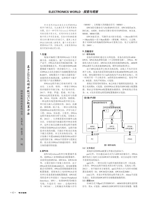
• 42•针对采用JTAG本地化方式更新FPGA 程序不够灵活,无法满足用户现场更新的问题,设计一种可用于Altera公司FPGA系列的远程升级方式。
采用FTP协议远程传输升级文件到设备端,设备内部ARM直接通过SPI操作EPCS存储芯片,重新上电后FPGA从EPCS载入新程序,整个升级过程不需要FPGA干预。
实践证明,方案使得FPGA 程序更新和调试更方便。
1.引言现场可编程门整列FPGA 由于其资源丰富,功能强大,被广泛应用在电子产品中。
FPGA 内部没有ROM 存储,掉电后配置数据丢失,所以通常将FPGA 配置数据下载到另一块存储芯片上,上电后FPGA 主动从存储芯片加载配置到内部RAM 中。
而配置芯片下载方式通常是厂家提供的本地调试器,这种程序下载手段不便于产品后期维护。
FPGA 远程升级已有相关研究(张永乐,王永勇,郑炜,一种基于FPGA 的在线程序升级方案:电子技术应用,2017;李强,罗超,夏威,何子述,FPGA 远程更新系统:仪表技术与传感器,2014;刘金福,武宏伟,杨胜姚,一种远程在线更新FPGA 程序的方法:单片机与嵌入式系统应用,2012;沈潇波,颜科峰,陈子龙,一种以太网在线更新FPGA 目标程序的方法:声学与电子工程,2016;刘永恩,王俊芳,FPGA 远程升级技术的分析与实现:无线电工程,2012),大多都需要对存储单元做分区,分别存放升级通信程序和业务程序。
这些方案无法解决如果远程升级程序错误导致FPGA 启动失败时,远程升级技术失效的问题,只能打开机壳以本地下载方式修复。
本文从该角度出发,设计依赖于外置ARM 处理器的FPGA 程序远程更新方案,FPGA 不需要参与更新过程,省去设计FPGA 升级通信程序,使得方案的通用性较强。
2.EPCSEPCS 是Altera 的串行配置器件系列,是FPGA 工业领域低成本配置器件,该系列包括EPCS4、EPCS16、EPCS128等,主要区别在于容量上的差异。
基于JTAG协议的ARM调试接口设计
第2 6卷第 2期
Vo . 6, 12 No. 2
西 华 大 学 学 报 ・ 自 然 科 学 版
J u a o h aUn v ri ’Nau a ce c o m l fXiu ies y t tr l in e S
20 0 7年 3月
通用 端 口。通 用 TA P包 括 5个 信 号 ( K, DI TC T , T) T I O,MS, R T) T S 。本 设 计 只提 供 了这 五 个 通 用 信 号线 , 体 设计 时 可根 据 不 同 AR 芯 片 的要 求 具 M
收 稿 日期 :060 .3 2 0 —40 作者简介 : 婧 (9 1 , 湖北省天门市人 , 胡 18 一)女, 硕士研究生 , 主要研究方向: 测控技术与仪器。
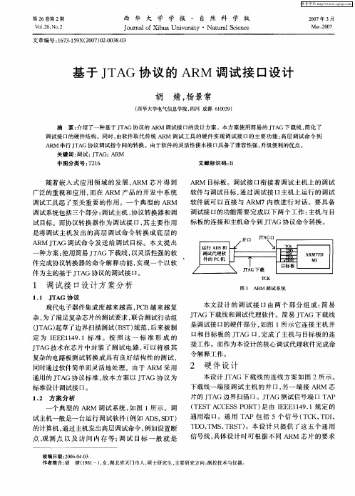
个 典 型 的 AR 调试 系统 , 图 1所 示 。 调 M 如
试主机 一般是 一 台运行 调 试 软 件 ( 如 A S,D 例 D S T) 的计算 机 , 过 主机发 出高层调 试命令 , 如设置 断 通 例 点 、 测 点 以 及 访 问 内存 等 ; 试 目标 一 般 就 是 观 调
文献 标 识 码 : B
随着 嵌 入 式 应 用 领 域 的 发 展 , R 芯 片得 到 A M 广泛 的重视 和应 用 , 而在 A M 产 品 的 开发 中 系 统 R
AR 目标 板 。调 试 接 口衔 接 着 调试 主机上 的调 试 M 软件 与调试 目标 , 过调 试 接 口主 机上 运行 的调 试 通
本文设 计 的 调 试 接 口 由 两 个 部 分 组 成 : 易 简 J A 下载线 和调试 代理 软 件 。简 易 J A 下 载线 T G T G 是调 试接 口的硬 件部 分 , 图 1所 示 它连 接 主 机并 如
利用 (JTAG) 边界扫描实现 Virtex FPGA 的配置和读回
© 2003–2007 Xilinx, Inc. All rights reserved. All Xilinx trademarks, registered trademarks, patents, and further disclaimers are as listed at /legal.htm . PowerPC is a trademark of IBM Inc. All other trademarks and registered trademarks are the property of their respective owners. All specifications are subject to change without notice.NOTICE OF DISCLAIMER: Xilinx is providing this design, code, or information "as is." By providing the design, code, or information as one possible implementation of this feature,application, or standard, Xilinx makes no representation that this implementation is free from any claims of infringement. Y ou are responsible for obtaining any rights you may require for your implementation. Xilinx expressly disclaims any warranty whatsoever with respect to the adequacy of the implementation, including but not limited to any warranties or representations that this implementation is free from claims of infringement and any implied warranties of merchantability or fitness for a particular purpose.SummaryThis application note demonstrates using a Boundary-Scan (JTAG) interface to configure and read back Virtex™ FPGA devices. Virtex devices have Boundary-Scan features that are compatible with IEEE Standard 1149.1. This application note is a complement to theconfiguration section in the Virtex data sheet and application note XAPP138 “Virtex FPGA Series Configuration and Readback.” Xilinx recommends reviewing both the data sheet and XAPP138 prior to reading this document.Note:The information in this application note also applies to the Virtex-E FPGA family.IntroductionThe IEEE 1149.1 Test Access Port (TAP) and Boundary-Scan architecture, commonly referred to as JTAG, is a popular testing method. JTAG is an acronym for the Joint Test Action Group, the technical subcommittee initially responsible for developing the standard. This standard provides a means to ensure the integrity of individual board-level components and their interconnections. With increasingly dense multi-layer PC boards and more sophisticatedsurface mounting techniques, Boundary-Scan testing is becoming widely used as an important debugging standard.Devices containing Boundary-Scan logic can send data out on I/O pins in order to testconnections between devices at the board level. The circuitry can also be used to send signals internally to test the device specific behavior. These tests are commonly used to detect opens and shorts at both the board and device level.In addition to testing, Boundary-Scan offers the flexibility for a device to have its own set of user-defined instructions. The added common vendor-specific instructions, such as configure and verify, have increased the popularity of Boundary-Scan testing and functionality.Boundary-Scan for Virtex DevicesThe Virtex family is fully compliant with the IEEE Standard 1149.1 Test Access Port andBoundary-Scan architecture. The architecture includes all mandatory elements defined in the IEEE 1149.1 Standard. These elements include the TAP , the TAP controller, the instruction register, the instruction decoder, the Boundary-Scan register, and the bypass register. The Virtex family also supports some optional instructions – the 32-bit identification register and a configuration register in full compliance with the standard. Outlined in the following sections are the details of the JTAG architecture for Virtex devices.Application Note: Virtex SeriesTest Access PortThe Virtex TAP contains four mandatory dedicated pins as specified by the protocol (Table 1).Three input pins and one output pin control the IEEE 1149.1 Boundary-Scan TAP controller. In addition to the required pins, there are optional control pins such as TRST (Test Reset) and enable pins, which can be found on devices from other manufacturers. Be aware of these optional signals when interfacing Xilinx devices with devices from different vendors because these signals can need to be driven. (To determine the set of signals that must be driven to enable IEEE 1149.1 compliance, see the vendor documentation for each device on the Boundary-Scan chain.)The TAP controller is a 16-state state machine (Figure 1). Mandatory TAP pins are as follows:•TMS - The sequence of states through the TAP controller is determined by the state of the TMS pin on the rising edge of TCK. TMS has an internal resistive pull-up to provide a logic High if the pin is not driven.•TCK - This pin is the JTAG test clock. It sequences the TAP controller and the JTAG registers in the Virtex devices.•TDI - This pin is the serial input to all JTAG instruction and data registers. The state of the TAP controller and the current instruction held in the instruction register determine which register is fed by the TDI pin for a specific operation. TDI has an internal resistive pull-up to provide a logic High to the system if the pin is not driven. TDI is applied into the JTAG registers on the rising edge of TCK.•TDO - This pin is the serial output for all JTAG instruction and data registers. The state of the TAP controller and the current instruction held in the instruction register determine which register (instruction or data) feeds TDO for a specific operation. TDO changes state on the falling edge of TCK and is active only during the shifting of instructions or data through the device. This pin is placed in a 3-state condition at all other times.Note:As specified by the IEEE Standard, the TMS and TDI pins all have internal pull-ups. These internalpull-ups of 50-150k Ω are active regardless of the mode selection.When using the Boundary-Scan operations in Virtex devices, the V CCO for Bank 2 must be at 3.3V for the TDO pin to operate at the required LVTTL level.Table 1: Virtex TAP Controller PinsPin Description TDI Test Data In TDO Test Data Out TMS Test Mode SelectTCKTest ClockTAP ControllerFigure1 diagrams a 16-state finite state machine. The four TAP pins control how the data is scanned into the various registers. The state of the TMS pin at the rising edge of the TCK determines the sequence of state transitions. There are two main sequences, one for shifting data into the data register and the other for shifting an instruction into the instruction register.Boundary-Scan Instruction SetTo determine the operation to be invoked, a 5-bit instruction is loaded into the instruction register. Table2 lists the available Boundary-Scan instructions for Virtex devices.Table 2: Virtex Boundary-Scan InstructionsBoundary-Scan Command Binary Code(4:0)DescriptionEXTEST00000Enables Boundary-Scan EXTEST operation SAMPLE00001Enables Boundary-Scan SAMPLE operation USER100010Access user-defined register 1USER200011Access user-defined register 2CFG_OUT00100Access the configuration bus for readback CFG_IN00101Access the configuration bus for configuration INTEST00111Enables Boundary-Scan INTEST operationThe mandatory IEEE 1149.1 commands are supported in Virtex devices along with several Xilinx vendor-specific commands. Virtex devices have a powerful command set. The EXTEST, INTEST, SAMPLE/PRELOAD, BYPASS, IDCODE, USERCODE, and HIGHZ instructions are all included. The TAP also supports two internal user-defined registers (USER1 and USER2) and configuration/readback of the device. The Virtex Boundary-Scan operations areindependent of the mode selection. The Boundary-Scan mode in Virtex devices overrides the other mode selections. For this reason, Boundary-Scan instructions using the Boundary-Scan register (SAMPLE/PRELOAD, INTEST, EXTEST) must not be performed during configuration. All instructions except USER1 and USER2 are available before the Virtex device is configured. After configuration, all instructions are available.JSTART is an instruction specific to the Virtex architecture and configuration flow. As described in Table 2, the JSTART instruction clocks the startup sequence when the appropriate bitgen option is selected. The instruction does not work correctly without the correct bitgen option selected.bitgen -g startupclk:jtagclk designName.ncdFor details on the standard Boundary-Scan instructions, EXTEST, INTEST, and BYPASS, refer to the IEEE Standard. The user-defined registers (USER1/USER2) are described in a later section of this application note.Boundary-Scan ArchitectureVirtex devices have several registers including all registers required by the IEEE 1149.1. In addition to the standard registers, the family contains optional registers for simplified testing and verification (Table 3).USERCODE 01000Enables shifting out user code IDCODE 01001Enables shifting out of ID codeHIGHZ 01010Places output pins in a 3-states condition while enabling the bypass registerJSTART 01100Clocks the start-up sequence when StartClk is TCK BYPASS 11111Enables BYPASSRESERVEDAll other codesXilinx reserved instructionsTable 3: Virtex JTAG RegistersRegister Name Register Length DescriptionInstruction register 5 bits Holds current instruction OPCODE and captures internal device statusBoundary-Scan register 3 bits per I/O Controls and observes input, output, and output enable Bypass register 1 bit Device bypass Identification register 32 bits Captures device IDJTAG configuration register32 bits Allows access to the configuration bus when using the CFG_IN or CFG_OUT instructions USERCODE register32 bitsCaptures user-programmable codeTable 2: Virtex Boundary-Scan Instructions (Continued)Boundary-Scan Command Binary Code(4:0)DescriptionBoundary-Scan Register The test primary data register is the Boundary-Scan register. The Boundary-Scan operation is independent of individual input/output block (IOB) configurations. Each IOB, bonded or unbonded, starts out as bidirectional with 3-state control. Later, it can be configured to be an input, output, or 3-state only. Therefore, three data register bits are provided per IOB (Figure2). When conducting a data register (DR) operation, the DR captures data in a parallel fashion during the CAPTURE-DR state. The data is then shifted out and replaced by new data during the SHIFT-DR state. For each bit of the DR, an update latch is used to hold the input data stable during the next SHIFT-DR state. The data is then latched during UPDATE-DR state when the TCK is Low.The update latch is opened each time the TAP Controller enters the UPDATE-DR state. Care is necessary when exercising an INTEST or EXTEST to ensure the proper data has been latched before exercising the command. This is typically accomplished by using theSAMPLE/PRELOAD instruction.Consider the presence of internal pull-ups and pull-down resistors when developing test vectors for testing opens and shorts. The IOB can be connected to an internal pull-up or pull-down resistor depending on the configuration state of the FPGA. (For more information on Virtex configuration modes and IOB connections to pull-up resistors, see the section on “Configuring through Boundary-Scan.”)•For an FPGA that is not yet configured, the Virtex configuration mode determines whether or not to connect the IOB to an internal pull-up resistor.•For a configured FPGA, the connectivity of an IOB to an internal pull-up or pull-down resistor depends on the user configuration of the IOB or the BitGen setting for unused pins.Figure2 shows the Virtex Boundary-Scan architecture.Bit SequenceThe order in each non-TAP IOB is described in this section. The input is first, followed by the output and finally the 3-state IOB control. The 3-state IOB control is closest to the TDO. The input-only pins contribute only the input bit to the Boundary-Scan I/O data register. The bit sequence of the device is obtainable from the “Boundary-Scan Description Language Files” (BSDL files) for the Virtex family. These files can be obtained from the Xilinx software download area. The bit sequence is invariant of the design. It always has the same bit order and the same number of bits.Bypass RegisterThe other standard data register is the single flip-flop BYPASS register. It directly passes data serially from the TDI pin to the TDO pin during a bypass instruction. This register is initialized to zero when the TAP controller is in the UPDATE-DR state.Instruction RegisterThe instruction register is a 5-bit register that loads the OPCODE necessary for the Virtex Boundary-Scan instruction set. This register loads the current OPCODE and captures internal device status.Configuration Register (Boundary-Scan)The configuration register is a 32-bit register. This register allows access to the configuration bus and readback operations.Identification RegisterThe Virtex devices have an identification register, commonly referred to as the IDCODE register. This register is based upon the IEEE Standard 1149.1 and allows easy identification of the part being tested or programmed through Boundary-Scan. Table4 lists the general format of the identification register.Table 4: Virtex Identification RegisterRevision CodePart Number ManufacturersIDLSB Family Code Part Size Code31 ... 2827 ... 2120 ... 1211 (10)XXXX0000011YYYYYYYYY0000 1001 0011Table5 lists specific IDCODES assigned to Virtex series FPGAs.Table 5: IDCODEs Assigned to Virtex Series FPGAsFPGA IDCODEXCV50v0610093hXCV50E v0A10093hXCV100v0614093hXCV100E v0A14093hXCV150v0618093hXCV200v061C093hXCV200E v0A1C093hXCV300v0620093hXCV300E v0A20093hXCV400v0628093hXCV400E v0A28093hXCV405E v0C28093hXCV600v0630093hXCV600E v0A30093hXCV800v0638093hXCV812E v0C38093hXCV1000v0640093hXCV1000E v0A40093hXCV1600E v0A48093hXCV2000E v0A50093hXCV2600E v0A5C093hXCV3200E v0A68093hNotes:1.The "v" in the IDCODE is the revision code field.USERCODE RegisterUSERCODE is supported in the Virtex family as well. This register allows a user to specify a design-specific identification code. The USERCODE can be programmed into the device and read back for verification at a later time. The USERCODE is embedded into the bitstream during bitstream generation (bitgen -g UserID option) and is valid only after configuration.USER1, USER2 RegistersThe USER1 and USER2 Boundary-Scan instructions are valid only after configuration. The user can define data registers associated with the USER1 and USER2 instructions within the FPGA design. After the FPGA is configured, the user can access the USER1 and USER2 data registers through the TAP pins.The BSCAN_VIRTEX library macro is required when creating the USER1 and USER2 data registers. This symbol is required only for driving internal scan chains (USER1 and USER2). The BSCAN_VIRTEX macro provides two user pins (SEL1 and SEL2) that determine the usage of USER1 or USER2 instructions respectively.For these instructions, two corresponding pins (TDO1 and TDO2) allow user scan data to be shifted out of TDO. In addition, there are individual clock pins (DRCK1 and DRCK2) for each user register. There is a common input pin (TDI) and shared output pins that represent the state of the TAP controller (RESET, SHIFT, and UPDATE). Unlike the earlier FPGA families where the BSCAN macro was required to dedicate the TAP pins for Boundary-Scan, the Virtex TAP pins are dedicated and do not require the BSCAN_VIRTEX macro for normal Boundary-Scan instructions or operations.The user implements the data register corresponding to the USER1 or USER2 Boundary-Scan instruction. Figure3 shows a sample implementation of a USER1 data register that is connected to the BSCAN_VIRTEX macro. For HDL, the BSCAN_VIRTEX macro must be instantiated in the design.Figure 3: BSCAN_VIRTEX (Sample Usage)UsingFigure4shows the Virtex Boundary-Scan Port Timing Waveforms.Boundary-Scan Array in VirtexDevicesFigure 4: Virtex Boundary-Scan Port Timing WaveformsTable6 lists characterization data for some of the most commonly requested timingparameters.For more information on the Startup sequence, bitstream, and internal configuration registersreferred to in this application note, review application note XAPP138 “Virtex FPGA SeriesConfiguration and Readback.”Table 6: Boundary-Scan Port Timing SpecificationsSymbol Parameter-6-5-4UnitsT TAPTCK TMS and TDI setup time before TCK 4.0 4.0 4.0nsminimumT TCKTAP TMS and TDI hold times after TCK 2.0 2.0 2.0nsminimumT TCKTDO TCK falling edge to TDO output valid11.011.011.0nsmaximumF TCK Maximum TCK clock frequency33.033.033.0MHzmaximumConfiguring through Boundary-ScanOne of the most common Boundary-Scan vendor-specific instructions is the configure instruction. An individual Virtex device is configured through JTAG on power-up using the TAP. If the Virtex device is configured on power-up, Xilinx recommends tying the mode pins to one of the following Boundary-Scan configuration mode settings.•101 (M2=1, M1=0, M0=1: contains no pull-ups on I/Os)•001 (M2=0, M1=0, M0=1: contains pull-ups on I/Os)Table7 lists the mode pin settings for all configuration modes, including Boundary-Scan modes.Table 7: Virtex Configuration ModesConfiguration Mode M2M1M0Pull-upsMaster Serial 000NoSlave Serial 111NoSelectMAP Mode110NoBoundary-Scan 101NoMaster Serial (with Pull-ups)100YesSlave Serial (with Pull-ups)011YesSelectMAP (with Pull-ups)010YesBoundary-Scan (with Pull-ups)001YesFigure5 shows the configuration flow for Virtex device configuration with JTAG. The sections that follow describe how the Virtex device can be configured as a single device through Boundary-Scan or as part of a multiple-device scan chain.A configured device can be reconfigured by toggling the TAP and entering the CFG_IN instruction after pulsing the PROG pin or issuing the shut-down sequence. (Refer to the “Reconfiguring through Boundary-Scan” section.) For additional details on power-up or the start-up sequence in Virtex devices, refer to application note XAPP138. In addition, application note XAPP058, "Xilinx In-System Programming Using an Embedded Microcontroller" has detailed information on using Virtex devices in an embedded solution.Note:Refer to XAPP058 for the recommended embedded solution.To configure a Virtex part as a single device through Boundary-Scan operations, use the stepslisted in Table8, which lists and describes the TAP controller commands required to configurea Virtex device. Ensure the bitstream is generated with the JTAG clock option:bitgen -g startupclk:jtagclk designName.ncdAlso, when programming with iMPACT software, verify that the most current version of softwareis used. Refer to Figure1 for the TAP controller states. These TAP controller commands areissued automatically if configuring the part with the iMPACT software.Table 8: Single Device Configuration SequenceTAP Controller Step Description Set and Hold Number of ClocksTDI TMS TCK 1On power-up, place a "1" on the TMS and clock the TCK five times.(This ensures starting in the TLR (Test-Logic-Reset) state.)X15 2Move into the RTI state.X01 3Move into the SELECT-IR state.X12 4Enter the SHIFT-IR state.X02 5Start loading the CFG_IN instruction .(1)010104 6Load the last bit of CFG_IN instruction when exiting SHIFT-IR(defined in the IEEE standard).011 7Enter the SELECT-DR state.X12 8Enter the SHIFT-DR state.X029Shift in the Virtex bitstream.(bit N (MSB) is the first bit in the bitstream (1))bit1...bit N0(Number of bitsin bitstream) −110Shift in the last bit of the bitstream.(bit0 (LSB) is shifted on the transition to EXIT1-DR)bit011 11Enter UPDATE-DR state.X11 12Enter the SELECT-IR state.X12 13Move to the SHIFT-IR state.X02 14Start loading the JSTART instruction.(1)(The JSTART instruction initializes the startup sequence.)110004 15Load the last bit of the JSTART instruction.011 16Move to the SELECT-DR state.X12 17Move to SHIFT-DR and clock the STARTUP sequence.(by applying a minimum of 12 clock cycles to the TCK).X0≥14 18Move to the UPDATE-DR state.X12 19Return to the RTI state. (The device is now functional).X01 1.In the TDI column, the right-most bit is shifted in first.It is possible to configure multiple Virtex devices in a chain. The devices in the JTAG chain are configured one at a time. The multiple device configuration steps are described generally to be applied to any size chain. Ensure the bitstream is generated with the JTAG clock option:bitgen -g startupclk:jtagclk designName.ncdRefer to Figure 1 for the following TAP controller steps:1.On power-up, place a “1” on the TMS and clock the TCK five times. This ensures startingin the TLR (Test-Logic-Reset) state.2.Load the CFG_IN instruction into the target device (and BYPASS in all other devices.)3.For a chain of Virtex devices, shift in leading zeros before the bitstream if the value of N isnot equal to zero. Use the following equation to determine the number of leading zeros for each bitstream. M is the targeted device position in the chain. As shown in Figure 6, the first device position in the chain is zero. N is the number of zeros required. Mod is the modulus operation.Example:The third device, position 2, in Figure 6 requires 30 leading zeros.The following example is for position 47:4.Go through RTI (RUN-TEST/IDLE).5.Repeat steps 2 through 4 for each successive device, repeat step 2 and step 4.6.Load the JSTART command into all devices.7.Go to SHIFT-DR and clock TCK 12 times.8.All devices are active at this point.N 32m –=od M 32------⎝⎠⎛⎞N 32M for M 32≤()–=N 322–=N 30number of leading 0s=N 32m –=od 4732------⎝⎠⎛⎞N 17number of leading 0s =Reconfiguring through Boundary-ScanNote:Refer to XAPP058 for the recommended embedded solution.Virtex FPGAs support reconfiguration through Boundary-Scan. The ability to reconfigure a Virtex FPGA with a different design enables an FPGA to perform multiple functions during different periods in time.FPGA reconfiguration comprises an initial reconfiguration setup procedure that prevents internal contention followed by the appropriate configuration sequence from the “Configuring through Boundary-Scan” section. (The appropriate configuration sequence from theConfiguring Through Boundary-Scan section depends on whether the Boundary-Scan chain comprises a single device or multiple devices.) If the initial reconfiguration setup procedure is not performed, then internal contention can occur as a new configuration overwrites an existing configuration within the FPGA.Either of the two following initial configuration setup methods prevent internal contention.•clear the entire internal configuration memory of the FPGA.•The alternate method is to perform a shutdown sequence. The shutdown sequence places the FPGA in a safe state for reconfiguration. When the FPGA is to be only partially reconfigured, the shutdown sequence is preferred because it allows the unchanged portion of the pre-existing configuration to remain within the configuration memory.Figure 6: Boundary-Scan Chain of DevicesNotes:1.The PROG pin should be deasserted during JTAG operations.The shutdown sequence is as follows. (For details on internal registers, see application note XAPP138.)1.Load the CFG_IN instruction into the JTAG instruction register. Next, go to the SHIFT-DRstate.2.In the SHIFT-DR state, shift in the following sequences in steps 2 through 4. (This writesthe COR (Configuration Option Register) with the SHUTDOWN bit = 1. It also indicates that the startup sequencer should perform a shutdown sequence.) The most significant bit (MSB) is the left bit and it is shifted in first.0011 0000 0000 0001 0010 0000 0000 0001-> Header: Write to COR0000 0000 1010 0000 1011 1111 0011 1101-> COR data sets SHUTDOWN = 13.Write the START command to the CMD (Command) register by shifting in the followingdata:0011 0000 0000 0000 1000 0000 0000 0001-> Header: Write to CMD0000 0000 0000 0000 0000 0000 0000 0101-> START command4.Write the precalculated Cyclic Redundancy Check (CRC) value to the CRC register, orwrite the Reset CRC Register (RCRC) command to the CMD register as shown:0011 0000 0000 0000 1000 0000 0000 0001-> Header: Write to CMD0000 0000 0000 0000 0000 0000 0000 0111-> RCRC command0000 0000 0000 0000 0000 0000 0000 0000-> flush pipe5.Now proceed to the SHIFT-IR and load the JTAG JSTART command into the instructionregister.6.Go to the SHIFT-DR and clock TCK 13 times to clock the shutdown sequence.7.Proceed to the SHIFT-IR state and load the CFG_IN instruction again.8.In the SHIFT-DR state, shift in the sequences in steps 8 and 9. This writes the AGHIGHcommand to the CMD register to assert the GHIGH_B signal. This prevents contention while writing configuration data.0011 0000 0000 0000 1000 0000 0000 0001-> Header: Write to CMD0000 0000 0000 0000 0000 0000 0000 1000-> AGHIGH command asserts GHIGH_B9.Write the COR with SHUTDOWN = 0 and go to RTI (RUN-TEST/IDLE) by shifting in thefollowing sequence:0011 0000 0000 0001 0010 0000 0000 0001-> Header: Write to COR0000 0000 1010 0000 0011 1111 1111 1111-> COR data sets SHUTDOWN = 00011 0000 0000 0000 1000 0000 0000 0001-> Header: Write to CMD0000 0000 0000 0000 0000 0000 0000 0101-> Header: Start command0011 0000 0000 0000 1000 0000 0000 0001-> Write to CMD0000 0000 0000 0000 0000 0000 0000 0111-> RCRC command0000 0000 0000 0000 0000 0000 0000 0000-> flush pipe10.Proceed to the SHIFT-IR state and load the JTAG JSTART instruction.11.Go to the SHIFT-DR and clock TCK 13 times to clock the simulation sequence.12.Go to the SHIFT-IR state and load the CFG_IN instruction again.13.In the SHIFT-DR state, shift in the following sequence steps 13 through 15. (This writes theConfiguration Option Register (COR) with the shutdown bit = 1. It also indicates that the startup sequencer should perform a shutdown sequence.)0011 0000 0000 0001 0010 0000 0000 0001-> Header: Write to COR0000 0000 1010 0000 1011 1111 0010 1101-> COR data sets SHUTDOWN = 114.Write Start command to command (CMD) register by shifting in the following data:0011 0000 0000 0000 1000 0000 0000 0001-> Header: Write to CMD0000 0000 0000 0000 0000 0000 0000 0101-> Start command15.Write the RCRC command to the CMD register as shown:0011 0000 0000 0000 1000 0000 0000 0001-> Header: Write to CMD0000 0000 0000 0000 0000 0000 0000 0111-> RCRC command0000 0000 0000 0000 0000 0000 0000 0000-> flush pipe16.Proceed to the SHIFT-IR and write the JSTART command into the Instruction register.17.Go to SHIFT-DR and clock TCK 13 times to clock the shutdown sequence.18.Go to the SHIFT-IR state and load the CFG_IN instruction.19.Enter the SHIFT-DR state and shift in the bitstream data.20.Proceed to SHIFT-IR and load the JSTART command into the instruction register.21.Proceed to SHIFT-IR and load the BYPASS instruction.Debugging ConfigurationTo verify successful configuration, there are several options. Some of the most helpful verification steps include using the TAP pins and the readback command. Using the Virtex TAP controller and status pins is discussed first.When using the TAP controller pins, TDO is driven only in the SHIFT-DR and SHIFT-IR state. If the output of the TDO can be changed by using an external pull-up, the TAP is not in SHIFT-IR or SHIFT-DR. If the TAP can be controlled precisely, use this to test the application.In JTAG configuration, the status pin (DONE) functions the same as in the other configuration modes. The DONE pin can be monitored to determine if a bitstream has been completely loaded into the device. If DONE is Low, the entire bitstream has not been sent or the start-up sequence is not finished. If DONE is High, the entire bitstream has been received correctly. When the FPGA detects a bitstream CRC error, DONE remains Low and INIT is driven Low.If the DONE pin is not asserted High, there are several possible reasons.1.The bitstream option bitgen -g startupclk:jtagclk described in the section“Software Support and Data Files” was not used.2.The JSTART instruction was not issued.3.There was an error in the bitstream.。
基于JTAG的ARM调试器实现
( 浙江大学计算机学院 浙江 杭 州 30 2 ) 10 7
摘
要
随着 u l u Ci x应用 与普及 , n 移植 u l u Ci x和在 Ln x开发平 台上设计嵌入式应用 系统都迫切 需要好 的调试 工具 , n iu 而现有 的
Wi o s 的调试 工具很难用 于 Lnx系统。介绍如何在 G B的基础上 , n w下 d iu D 低成 本实现嵌入式板 的J A T G调试 。
如下 :
・ 取指
・ 译码
从存储器 中取 出指令 , 放人指令流水线。
指令被译码 , 并为 下一周期 准备数据 通路的控制
A M处理器也提供 了典 型的 m G调试 方法 ( R 用户可 以添 加观察点 和断点) 目标 系统 与主机 之间通 过扩 展 的 J A T G测 试
为 了提高 自主知识产 权 , 破技术 垄 断 , 打 开放 源码 的 G U N
工程越来越受到重视。在嵌 人式领域 , u l u 以 Ci x为代表 的应用 n
考虑 , 而通常应 用 , 编译 器 和链接 器都 屏蔽 了这 些 差别 。另 外
A M的P R c值在 因为不 同原 因进人调试模式时 , 判断也有不 同 , 恢复断点时要根据不 同的中断原 因来恢 复不同的 P c值 。
1 A M 的体 系结构 R
A M( da cdR S ahns , 可 以 认 为 是 一 个 公 司 的 R A v e IC M c i ) 既 n e
国际标准测试 协 议 (E E 19 1 容 ) 主 要用 于 芯片 内部 测 IE 14 . 兼 ,
试 。标准 的 J A T G接 口是 5线 :MS T K、D 、 D T S , 别 T 、C T IT O、 R T 分
用ARM对FPGA进行配置的原理与方法
用ARM对FPGA进行配置的原理与方法
0引言
基于SRAM工艺FPGA在每次上电后需要进行配置,通常情况下FPGA的
配置文件由片外专用的EPROM来加载。
这种传统配置方式是在FPGA的功能相对稳定的情况下采用的。
在系统设计要求配置速度高、容量大、以及远程升级时,这种方法就显得很不实际也不方便。
本文介绍了通过ARM对可编程器件进行配置的的设计和实现。
1 配置原理与方式
1.1配置原理
在FPGA正常工作时,配置数据存储在SRAM单元中,这个SRAM单元也被称为配置存储器(Configuration RAM)。
由于SRAM是易失性的存储器,因此FPGA在上电之后,外部电路需要将配置数据重新载入到片内的配置RAM中。
在芯片配置完成后,内部的寄存器以及I/O管脚必须进行初始化。
等初始化完成以后,芯片才会按照用户设计的功能正常工作。
1.2配置方式
根据FPGA在配置电路中的角色,其配置数据可以使用3种方式载入到目标器件中:
-FPGA主动(Active)方式;
-FPGA 被动(Passive)方式;
-JTAG 方式;
在FPGA 主动方式下,由目标FPGA来主动输出控制和同步信号(包括配置时钟)给专用的一种串行配置芯片,在配置芯片收到命令后,就把配置数据发到FPGA,完成配置过程。
在被动方式下,由系统中的其他设备发起并控制配置。
基于JTAG的ARM嵌入式系统调试技术实现及应用

基于JTAG的ARM嵌入式系统调试技术实现及应用
殷伟凤
【期刊名称】《浙江万里学院学报》
【年(卷),期】2009(22)2
【摘要】文章介绍了JTAG结构及其TAP控制器的控制机制,描述了ARM芯片的JTAG调试原理,给出了一种基于JTAG接口协议的ARM调试设计方案及其软硬件实现,并利用JTAG接口进行硬件设备的远程调试.
【总页数】6页(P17-21,30)
【作者】殷伟凤
【作者单位】浙江万里学院,浙江,宁波,315100
【正文语种】中文
【中图分类】I210.6
【相关文献】
1.基于ARM嵌入式系统和GPRS无线通讯技术的新型汽车故障诊断仪的实现 [J], 黄伟
2.基于JTAG的54xDSP并行自举实现方法及应用 [J], 陈迪楼
3.基于EmJTAG的ARM嵌入式系统调试工具 [J], 姜立娣;沈建华
4.基于JTAG的ARM芯片系统调试 [J], 杨峰;张根宝;田泽;万永波
5.基于JTAG的ARM芯片系统调试 [J], 杨峰;张根宝;田泽;万永波
因版权原因,仅展示原文概要,查看原文内容请购买。
基于JTAG的ARM芯片系统调试.

基于JTAG的ARM芯片系统调试1 引言随着嵌入式处理器性能的逐步提高,运算速度越来越快、处理的数据量越来越大,传统的调试方法如ROM驻留监控程序以及串口调试工具已经不能满足要求。
ARM处理器采用一种基于JTAG的ARM的内核调试通道,它具有典型的ICE功能,基于ARM的包含有Embedded ICE(嵌入式在线仿真器)模块的系统芯片通过JTAG端口与主计算机连接。
通过配置支持正常的断点、观察点以及处理器和系统状态访问,完成调试。
为了对代码进行实时跟踪,ARM的提供了嵌入式跟踪单元(Embedded Trace Macrocell),对应用程序的调试将更加全面。
2 JTAG边界扫描原理“JTAG边界扫描”或IEEE1149标准[1]是由“测试联合行动组”(Joint Test Action Group,简称JTAG)开发的针对PCB的“标准测试访问接口和边界扫描结构”的标准。
这个标准是ARM处理器调试的基础。
2.1 硬件电路JTAG边界扫描测试接口的一般结构[2]如图1所示。
JTAG边界扫描硬件电路主要由三部分构成:1) TAP控制器。
测试访问端口(TAP)控制器,是由TMS控制状态转换的状态机。
2) 指令寄存器。
用于存储JTAG边界扫描指令,通过它可以串行的输入并执行各种操作指令。
3) 数据寄存器。
特定芯片的行为由测试指令寄存器的内容决定。
测试指令寄存器可用来选择各种不同的数据寄存器。
2.2 边界扫描测试信号支持这个测试标准的芯片必须提供5个专用信号接口:? TRST:测试复位输入信号,低电平有效,为TAP控制器提供异步初始化信号。
? TCK:JTAG测试时钟,独立于任何系统时钟,为TAP控制器和寄存器提供测试参考。
? TMS:TAP控制器的测试模式选择信号,控制测试接口状态机的操作。
? TDI:JTAG指令和数据寄存器的串行输入端,给边界扫描链或指令寄存器提供数据。
? TDO:TAG指令和数据寄存器的串行输出。
基于JTAG的FPGA配置方法与电路设计

I
西安电子科技大学硕士学位论文
电路已经达到设计要求,满足产品的相应指标,和国外产品相比,也具备很强的竞争 实力。这对研发高端的 FPGA 芯片以及提升综合国力与振兴民族产业都有积极的意 义。 关键词:FPGA, IEEE 1149.1 标准, IEEE 1532 标准, JTAG 配置, 边界扫描测试
1.It lays the foundation for circuit design that reading corresponding literature, researching IEEE 1149.1 standard and IEEE 1532 standard, studying their principles, structures and the logical function of the components, and understanding the architecture and configuration principle of FPGA.
II
ABSTRACT
ABSTRACT
FPGA (Field Programmable Gate Array) has high-powered and programmable advantage. Users be able to alter configuration data of FPGA to achieve designed function on the basis of their needs. At present FPGA has been widely used for major space engineerings, such as manned space, high track warning, lunar and mars exploration, Beidou satellite navigation, space station and soon.
ARM与FPGA通用GPMC总线接口设计实现

ARM与FPGA通用GPMC总线接口设计实现引言:随着计算机科学的不断发展,特别是嵌入式系统的迅速发展,ARM和FPGA的结合越来越受到关注。
ARM作为一种高性能、低功耗的处理器,广泛应用于移动设备、智能家居和工业自动化等领域。
而FPGA则具有灵活可重构的特点,可以实现各种不同的数字电路和逻辑功能。
为了实现ARM与FPGA之间的通信,我们可以采用GPMC(General-Purpose Memory Controller)总线接口。
GPMC是一种高性能、灵活的AMBA(ARM Advanced Microcontroller Bus Architecture)总线接口,主要用于处理大容量主存储器和外部设备的访问。
设计思路:1.通过FPGA实现GPMC总线控制器,与ARM处理器相连。
2.根据GPMC总线协议规范,实现数据、地址、控制和时钟信号的交互。
3.通过GPMC总线控制器,实现ARM与FPGA之间的数据传输和通信。
设计细节:1.GPMC总线控制器的设计:-实现GPMC总线接口的时序控制逻辑,包括数据传输的读写控制和时钟同步。
-实现对外设的地址和数据的读写控制。
-实现GPMC总线控制器与ARM处理器的接口逻辑。
2.GPMC总线接口的数据传输:-对于数据的读取,ARM发送读命令和地址给GPMC控制器,控制器从外设读取数据,并将数据发送给ARM。
-对于数据的写入,ARM发送写命令、地址和数据给GPMC控制器,控制器将数据写入外设。
3.GPMC总线接口的时钟同步:-ARM和FPGA可能有不同的时钟频率,需要实现时钟同步。
- 可以使用FPGA中的PLL(Phase-Locked Loop)模块,将ARM的时钟频率转换为与FPGA相同的频率。
4.GPMC总线接口的地址映射:-ARM和FPGA之间的地址映射需要一致,以确保ARM访问FPGA上的正确地址。
-可以通过使用地址转换模块来实现地址映射。
5.GPMC总线接口的信号标准:-GPMC总线接口的信号标准需要符合AMBA总线接口规范。
基于JTAG的ARM调试器实现

基于JTAG的ARM调试器实现
基于JTAG的ARM调试器实现
基于JTAG的ARM调试器实现
陆晗;潘雪增;平玲娣
【期刊名称】《计算机应用与软件》
【年(卷),期】2007(024)002
【摘要】随着uClinux应用与普及,移植uClinux和在Linux开发平台上设计嵌入式应用系统都迫切需要好的调试工具,而现有的Windows下的调试工具很难用于Linux系统.将介绍如何在GDB的基础上,低成本实现嵌入式板的JTAG调试.
【总页数】3页(P137-139)
【作者】陆晗;潘雪增;平玲娣
【作者单位】浙江大学计算机学院,浙江,杭州,310027;浙江大学计算机学院,浙江,杭州,310027;浙江大学计算机学院,浙江,杭州,310027 【正文语种】中文
【中图分类】TP3
【相关文献】
1.一种基于CPLD的高速JTAG调试器的设计与实现 [J], 张红;余建
2.基于JTAG的ARM7TDMI处理器调试原理及实现 [J], 刘文超;潘永才
3.基于JTAG接口实现ARM的FPGA在线配置 [J], 黄志海;周小会;糜正琨
4.基于JTAG的片上调试器与调试系统的设计实现 [J], 常志恒;肖铁军;史顺波
5.基于JTAG的ARM嵌入式系统调试技术实现及应用 [J], 殷伟凤
因版权原因,仅展示原文概要,查看原文内容请购买。
基于ARM的FPGA加载配置实现

基于ARM的FPGA加载配置实现摘要:实现了一种全集成可变带宽中频宽带低通滤波器,讨论分析了跨导放大器-电容(OTA—C)连续时间型滤波器的结构、设计和具体实现,使用外部可编程电路对所设计滤波器带宽进行控制,并利用ADS软件进行电路设计和仿真验证。
仿真结果表明,该滤波器带宽的可调范围为1~26 MHz,阻带抑制率大于35 dB,带内波纹小于0.5 dB,采用1.8 V电源,TSMC 0.18μm CMOS工艺库仿真,功耗小于21 mW,频响曲线接近理想状态。
关键词:Butte引言基于SRAM工艺FPGA在每次上电后需要进行配置,通常情况下FPGA的配置文件由片外专用的EPROM来加载。
这种传统配置方式是在FPGA的功能相对稳定的情况下采用的。
在系统设计要求配置速度高、容量大、以及远程升级时,这种方法就显得很不实际也不方便。
本文介绍了通过ARM对可编程器件进行配置的的设计和实现。
1 配置原理与方式1.1 配置原理在FPGA正常工作时,配置数据存储在SRAM单元中,这个SRAM单元也被称为配置存储(Configuration RAM)。
由于SRAM是易失性的存储器,因此FPGA在上电之后,外部电路需要将配置数据重新载入到片内的配置RAM中。
在芯片配置完成后,内部的寄存器以及I/O管脚必须进行初始化。
等初始化完成以后,芯片才会按照用户设计的功能正常工作。
1.2 配置方式根据FPGA在配置电路中的角色,其配置数据可以使用3种方式载入到目标器件中:·FPGA主动(Active)方式;·FPGA 被动(Passive)方式;·JTAG 方式;在FPGA 主动方式下,由目标FPGA来主动输出控制和同步信号(包括配置时钟)给专用的一种串行配置芯片,在配置芯片收到命令后,就把配置数据发到FPGA,完成配置过程。
在被动方式下,由系统中的其他设备发起并控制配置过程,FPGA只输出一些状态信号来配合配置过程。
基于ARM与FPGA的可重构设计.

基于ARM与FPGA的可重构设计可重构技术是指利用可重用的软硬件资源,根据不同的应用需求,灵活地改变自身体系结构的设计方法。
常规SRAM工艺的FPGA都可以实现重构,利用硬件复用原理,本文设计的可重构控制器采用ARM核微控制器作为主控制器,以FPGA芯片作为协处理器配合主控制器工作。
用户事先根据需求设计出不同的配置方案,并存储在重构控制器内部的存储器中,上电后,重构控制器就可以按需求将不同设计方案分时定位到目标可编程器件内,同时保持其他部分电路功能正常,实现在系统灵活配置,提高系统工作效率。
1 SVF格式配置文件很多嵌入式系统中都用到了FPGA/CPLD等可编程器件,在这些系统中利用SVF格式配置文件就可以方便地通过微控制器对可编程器件进行重新配置。
目前可编程芯片厂商的配套软件都可以生成可编程器件的SVF格式配置文件,串行矢量格式(SVF)是一种用于说明高层IEEE 1149.1(JTAG)总线操作的语法规范。
SVF由Texas Instruments开发,并已成为数据交换标准而被Teradyne,Tektronix等JTAG测试设备及软件制造商采用。
Xilinx的 FPGA以及配置PROM 可通过JTAG接口中TAP控制器接收SVF格式的编程指令。
由于SVF文件由ASCII语句构成,它要求较大的存储空间,并且存储效率很低,无法胜任嵌入式应用。
为了在嵌入式系统中充分利用其有限的存储空间,并不直接利用SVF 文件对可编程器件进行在系统编程,而是将SVF文件转换成另一种存储效率比较高的二进制格式的文件,把它存储在数据存储器中。
Xilinx公司提供用于创建器件编程文件的iMPACT工具,该工具随附于标准Xilinx ISETM软件内。
iMPACT软件能自动读取标准的BIT/MCS器件编程文件,并将其转换为紧凑的二进制XSVF格式。
本设计是基于“ARM处理器+FPGA”结构的重构控制器,重构控制器中的FPGA能够根据ARM处理器传送来的命令,对目标可编程器件 JTAG接口进行控制,并负责解译XSVF格式的配置文件信息,生成xilinx器件所用的编程指令、数据和控制信号(TMS,TDI,TCK序列)向目标可编程器件的JTAG TAP控制器提供所需的激励,从而执行最初在XSVF文件内指定的编程和(可选的)测试操作。
DSP 和 JTAG 接口的 FPGA 系统在线编程方法

DSP 和 JTAG 接口的 FPGA 系统在线编程方法邱育杰;管国云;聂在平;李颖【期刊名称】《单片机与嵌入式系统应用》【年(卷),期】2014(14)11【摘要】SRAM-based FPGA has higher power consumption at high temperature,and its memory configuration is invalid when power-fail occurs.Besides,FPGA needs to be upgraded in some systems.A in-system programming method for FLASH-based FPGA is realized by using RAM as the stream carrier of configuration code and DSP as master controller.Configuration code of FPGA is downloaded to external RAM through serial ports of DSP.The clearing and programming of Flash and in-system programming of FPGA are implemen-ted through driving FPGA′s JTAG interface by DSP′s GPIO.Experimental results show that the system can work stably at 1 50 de-grees.The method has high reliability and convenient operation.%基于 SRAM 的 FPGA 在高温下功耗较高,配置存储器时具有掉电易失性,且某些系统需要对 FPGA 进行在线升级以升级系统。
- 1、下载文档前请自行甄别文档内容的完整性,平台不提供额外的编辑、内容补充、找答案等附加服务。
- 2、"仅部分预览"的文档,不可在线预览部分如存在完整性等问题,可反馈申请退款(可完整预览的文档不适用该条件!)。
- 3、如文档侵犯您的权益,请联系客服反馈,我们会尽快为您处理(人工客服工作时间:9:00-18:30)。
基于JTAG接口实现ARM的FPGA在线配
置
引言随着通信技术的发展,出现越来越多的无线接人技术,为了解决不同标准间的互通和兼容,人们提出了软件无线电(SoftwareDefinedRadio,SDR)技术。
SDR技术要求通信终端具有可重配置能力,根据特定通信网络情况,动态地改变调制/解调、编解码、交织/解交织等方案。
SDR终端的实现往往都是基于可重配置的硬件环境,如现场可编程逻辑阵列(FieldProgrammableGateArray,FPGA)、数字信号处理器(DigitalSignalProcessor,DSP),而不是专
引言
随着通信技术的发展,出现越来越多的无线接人技术,为了解决不同标准间的互通和兼容,人们提出了软件无线电(Sof tware Defined Radio,SDR)技术。
SDR技术要求通信终端具有可重配置能力,根据特定通信网络情况,动态地改变调制/解调、编解码、交织/解交织等方案。
SDR终端的实现往往都是基于可重配置的硬件环境,如现场可编程逻辑阵列(Field Programmable Gate Array,FPGA)、数字信号处理器(Digital Signal Processor,DSP),而不是专用集成电路(Application Specific Integrated Circuit,AS IC)等特定的硬件电路和芯片。
在线配置(In Sys—tem Programming,ISP)或者动态配置FPGA就是一种重要的SDR实现技术。
本文介绍作者开发实现的一种基于ARM的嵌入式Linux下通过JTAG接口动态配置FPGA的方法。
系统使用三星公司基于ARM9的S3C2410处理器芯片,Altera公司CycloneII系列的EP2C70 FPGA芯片,ARM处理器上运行基于S3C2410裁剪后的嵌入式Linux系统,内核版本为2.4.18。
1 FPGA的配置方式及配置文件
Altera公司CycloneII系列FPGA芯片,是Altera公司推出的基于90 nm工艺制造、低成本的FPGA,主要面向数字终端、手持设备等对成本敏感的应用领域。
EP2C70拥有68 416个逻辑单元,115200位RAM,150个乘法器模块,是CycloneII系列处理能力最强的芯片。
与大部分FPGA一样,CycloneII系列FPGA的配置信息保存在SRAM中,掉电后就丢失配置信息,每次上电后需要重新配置。
CycloneII系列FPGA支持3种配置方式:主动串行(AS)方式、被动串行(PS)方式、JTAG方式。
在主动串行和被动串行两种方式中,FPGA芯片支持在配置过程中对配置数据进行解压缩,也就是配置数据可以采用压缩格式存放;而使用JTAG配置时,FPGA芯片不支持解压缩过程,不能采用压缩格式的配置数据。
不同的配置方式,往往要求不同格式的配置文件。
使用Altera公司提供的QuartusII集成开发环境可以生成各种配置文件。
QuartusII默认产生.sof和.pof格式的配置文件,基于ARM的嵌入式Linux中对FPGA进行JTAG下载,必须使用.jam或者.jbc格式的配置文件。
2 JTAG接口工作方式
JTAG接口是一个业界标准,主要用于芯片测试和配置等功能,使用IEEE Std 1149.1联合边界扫描接口引脚。
JTAG最初用于芯片功能的测试,其工作原理是在器件内部定义一个测试访问端口(Test Access Port,TAP),通过专用的JTAG测试工具对内部节点进行测试和调试。
TAP是一个通用的端口,外部控制器通过TAP可以访问芯片提供的所有数据寄存器和指令寄存器。
现在JTAG接口还常用于芯片的在线配置,对PLD、Flash等器件进行配置。
为了完成系统的调试,任何原型系统都支持JTAG配置方式,因而JTAG配置也就成为最广泛支持的配置方式。
不同厂商和不同型号的绝大部分FPGA芯片都支持JTAG配置方式。
在Altera公司的FPGA芯片中,JTAG配置方式比其他任何一种配置方式的优先级都高。
JTAG允许多个器件通过JTAG接口串联在一起,形成一个JTAG链,实现对各个器件分别测试和配置。
JTAG接口由4个必需的信号TDI、TD0、TMS和TCK,以及1个可选信号TRST构成。
3 Jam STAPL套件
在嵌入式Linux环境中,使用JTAG接口配置FP—GA,必须使用标准测试与编程语言(Standard Test AndProgramming Language,STAPL)标准。
STAPL 是一种专门用于描述可编程逻辑设备(Programmable Logic De—vice,PLD)配置文件的编程语言,由EIA/JEDEC组织制定标准。
使用STAPL描述的配置文件具有通用性,独立于PLD生产厂商。
Jam STAPL是Altera公司提供的支持STAPL的套件。
使用Jam STAPL 进行配置包含两部分,Jam Player(Jam解释器或者称为Jam虚拟机)和Jam配置文件。
Jam Player运行在微处理器中,读取Jam文件并解析Jam文件表达的内容,在JTAG接口上产生用于配置的二进制数据流并读取反馈数据。
Jam STAPL的工作方式如图l所示。
利用PLD厂商提供的集成开发环境Jam Composer,可以产生Jam配置文件(该文件包含目标没备、应用数据等完整配置信息,与厂商和配置平台无关)。
然后使用Jam Player解释并产生JTAG配置数据,对JTAG链中的各个设备进行配置。
使用Jam STAPL进行配置时,针对不用的应用和不同的目标设备(不同型号或者不同厂商),只需要改变Jam配置文件,而无需改变Jam Player。
因为Jam Player不包含任何与应用或者设备相关的信息,它只负责解析Jam配置文件中的内容。
它的工作方式与Java编程语言非常相似,Jam P1ayer相当于Java虚拟机,而Jam文件相当于编译之后的Java字节码文件(.class文件)。
Jam配置文件有两种格式:
①ASCII文本格式文件,也就是用STAPL描述的配置源文件,文件后缀名是.jam。
该格式便于阅读和理解,但由于采用ASCII文本编码,体积较大。
②字节码(Byte—Code)格式文件,STAPL源文件编译好之后的字节码文件,文件后缀名是“.jbc”。
对于同样的配置信息,该格式比.jam格式体积小,节省存储空间;其缺点是,无法直接阅读其中的配置信息。
与之对应,Jam Player也有两种:普通Jam Player,负责对.jam文件的解释;Jam Byte一Code Player,负责对.jbc文件的解释。
从AItera官方网站上可以免费下载到用C语言编写的两种Player源代码。
4 系统设计与实现
4.1 系统硬件设计
系统硬件连接方案如图2所示。
系统中只使用JTAG配置方式,所以与AS、PS相关的nCONFIG、MSELO和MSEL1引脚都不使用,而将nCONFIG拉高,MSELO和MSEL1接地。
DATA0和DCLK引脚可以任意配置,在这里都接地。
使用S3C2410的通用引脚GPB7、GPB8、GPB9、GPBlO引脚分别作为JTAG接口的TMS、TDl、TCK和TDO。
