GAMBIT实例教程-0_使用指南向导
GAMBIT用户手册_4_GAMBIT菜单命令
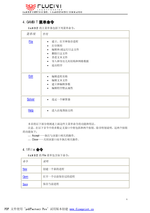
4.GAMBIT菜单命令GAMBIT的主菜单条包括下列菜单命令:菜单项作用File•建立、打开和保存进程•打印图形•编辑和/或运行日志文件•删除日志文件•查看文本文件•导入和导出几何结构和网格数据•退出程序Edit•编辑进程名称•编辑文本文件•建立和编辑参数•编辑程序默认属性Solver•选定一个解算器Help•进入在线帮助文档本章的以下部分将阐述上面这些主菜单命令的功能和用法。
注意,在以下章节中的多数定义窗口中将包括和两个按钮。
除非特别说明,这两个按钮的功能如下:—Accept——执行与该窗口相关的操作。
—Close——关闭该窗口而不执行相关操作。
4.1File命令GAMBIT的File菜单包含如下命令:命令说明New创建一个新的进程Open打开一个以前保存过的进程Save保存当前进程Save As以一个新的名称保存当前进程Print Graphics打印当前显示的图形Run Journal 显示并允许用户编辑和执行任何日志文件中的命令Clean Journal从GAMBIT日志文件中删除外部命令、信息和符号View File 显示当前的文本文件Import导入几何结构和网格数据Export导出几何结构和网格数据Exit终止程序的执行4.1.1 New当用户从File菜单中选择了New,GAMBIT打开Create New Session窗口。
Create New Session窗口允许用户建立和命名一个新进程。
要创建一个新的进程,用户必须指定如下项目:—进程标识—保存选项另外,除了上述两项,GAMBIT也允许用户设定进程的标题。
进程标识包含与该新进程相关联的GAMBIT数据文件的基本名称。
(有关数据文件的内容和格式的说明,请参阅本向导的第二章。
)保存选项决定GAMBIT在建立新进程之前是否保存现有进程的数据。
进程标题包含了该进程的一般说明。
定义进程标识进程标识可以由任意的字母组合和/或GAMBIT所运行的系统环境下允许的有效文件名中所包含的符号组成。
Gambit使用教程(三维)
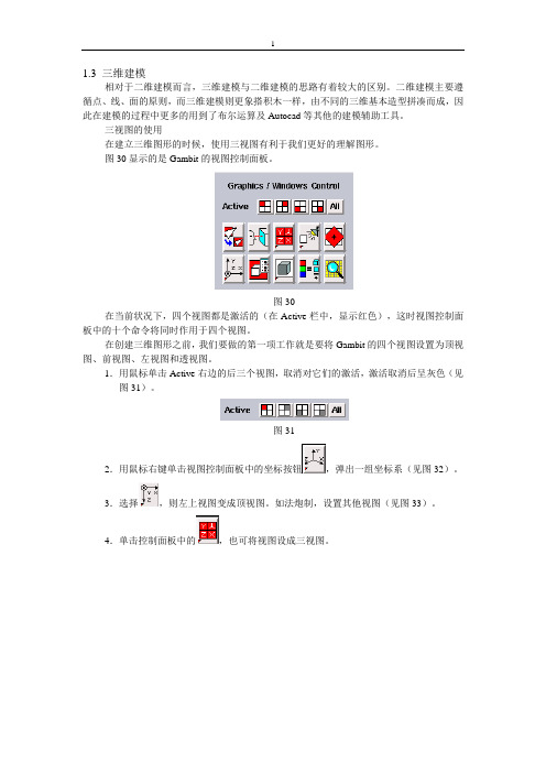
图12
5.创建一个直径60mm,高180mm的圆柱,将其沿X轴移动36mm(图13)。
图13
6.利用uion命令,将视图中所有的几何体合成一个几何体volume1。
7.创建一个长216,宽60,高60的长方体,将其沿Y轴移动-30个单位。
(一)在Autocad中创建维多辛斯基曲线
1.利用pline命令将维多辛斯基曲线上的各点坐标连成一条折线。
2.利用pedit命令使折线光滑。
3.创建其他轮廓线(见图2)。
喷嘴的具体参数见参考图纸。
图2 CAD中创建的喷嘴轮廓线
(二)输出为ACIS的.sat文件
对于二维图形要输出为.sat文件,必须是一个region图形。
3.划分外区域的网格,网格类型为submap(见图8)。
图8
(六)定义边界条件
1.选择solver/fluent5。
2.单击 按钮。
3.定义各边界条件。
4.单击 ,将两个面设为同一个连续体(fluid)(见图9)
图9
注意:对于一个复杂的几何体而言,在网格划分时必定要划分为多个区域。将这些区域定义到一个统一的连续体中,这样,不同区域间的分隔线就会被默认为内部网格点。
图6
2.喷嘴外部的面(face2),定义轴线上网格点为240个。定义喷嘴外轮廓线的网格点数(见图7)
图7
注意:对于网格的划分,如果要求控制网格的密度,可以遵循从线到面的原则,但是对于多边形区域而言,不能将所有边的网格点都定死,必须有一些边不定义网格。如四边形区域,一般只定义相邻两个边的网格。至于多边形区域怎样定义边上的网格,必须在实践中不断的尝试。
gambit 操作指南
GAMBIT 2.3Tutorial GuideMarch 2006Licensee acknowledges that use of Fluent, Inc.’s products can only provide an imprecise estimation of possible future performance and that additional testing and analysis, independent of the Licensor’s products, must be conducted before any product can be finally developed or commercially introduced. As a result, Licensee agrees that it will not rely upon the results of any usage of Fluent, Inc.’s products in determining the final design, composition, or structure of any product.© 2006 by Fluent, IncorporatedAll Rights Reserved. No part of this document may be reproduced or otherwise used in any form without express written permission from Fluent, Incorporated.Airpak, FIDAP, FLUENT, GAMBIT, Icepak, MixSim, and POLYFLOW are registered trademarks of Fluent, Inc.ImageMagick is © 1996 E.I. du Pont de Nemours and Co.All other products or name brands are trademarks of their respective holders.For GAMBIT Technical Support contact information, visit the Fluent, Inc. Web site at .Fluent, IncorporatedCenterra Resource Park10 Cavendish CourtLebanon, NH 03766iiiTABLE OF CONTENTS0. USING THIS TUTORIAL GUIDE.................................................... 0-1 0.1 What’s in This Guide .....................................................................................0-10.2 How to Use This Guide...................................................................................0-20.3 Font Conventions............................................................................................0-30.4 Using the Mouse..............................................................................................0-40.4.1 Menus and Forms .................................................................................0-40.4.2 Graphics Window.................................................................................0-40.5 GUI Components ............................................................................................0-80.5.1 Graphics Window.................................................................................0-90.5.2 Main Menu Bar ....................................................................................0-90.5.3 Operation Toolpad ...............................................................................0-90.5.4 Form Field..........................................................................................0-110.5.5 Global Control Toolpad .....................................................................0-120.5.6 Description Window ..........................................................................0-120.5.7 Transcript Window and Command Text Box ....................................0-121. CREATING AND MESHING BASIC GEOMETRY....................... 1-1 1.1 Prerequisites ....................................................................................................1-11.2 Problem Description.......................................................................................1-21.3 Strategy............................................................................................................1-31.4 Procedure.........................................................................................................1-4Step 1: Create a Brick....................................................................................1-5Step 2: Create an Elliptical Cylinder .............................................................1-8Step 3: Unite the Two Volumes ..................................................................1-10Step 4: Manipulate the Display ...................................................................1-12Step 5: Mesh the Volume ............................................................................1-14Step 6: Examine the Mesh...........................................................................1-16Step 7: Save the Session and Exit GAMBIT...............................................1-201.5 Summary .......................................................................................................1-212. MODELING A MIXING ELBOW (2-D)........................................... 2-1 2.1 Prerequisites ....................................................................................................2-12.2 Problem Description.......................................................................................2-22.3 Strategy............................................................................................................2-32.4 Procedure.........................................................................................................2-4Step 1: Select a Solver...................................................................................2-4Step 2: Create the Initial Vertices..................................................................2-5Step 3: Create Arcs for the Bend of the Mixing Elbow..............................2-10Step 4: Create Straight Edges......................................................................2-13Step 5: Create the Small Pipe for the Mixing Elbow ..................................2-15Step 6: Create Faces From Edges................................................................2-23Table of ContentsivStep 7: Specify the Node Distribution.........................................................2-26Step 8: Create Structured Meshes on Faces ................................................2-34Step 9: Set Boundary Types ........................................................................2-37Step 10: Export the Mesh and Save the Session .........................................2-412.5 Summary .......................................................................................................2-423. MODELING A THREE-PIPE INTERSECTION (3-D) ................... 3-1 3.1 Prerequisites ....................................................................................................3-13.2 Problem Description.......................................................................................3-23.3 Strategy............................................................................................................3-33.4 Procedure.........................................................................................................3-5Step 1: Select a Solver...................................................................................3-5Step 2: Create the Geometry..........................................................................3-5Step 3: Decompose the Geometry .................................................................3-9Step 4: Journal Files ....................................................................................3-19Step 5: Turn Off Automatic Smoothing of the Mesh..................................3-22Step 6: Apply Boundary Layers at Walls ....................................................3-24Step 7: Mesh the Sphere Octant Volume ....................................................3-28Step 8: Mesh the Pipe Volumes ..................................................................3-30Step 9: Examine the Quality of the Mesh....................................................3-41Step 10: Set Boundary Types ......................................................................3-443.5 Summary .......................................................................................................3-494. MODELING A COMBUSTION CHAMBER (3-D) ......................... 4-1 4.1 Prerequisites ....................................................................................................4-14.2 Problem Description.......................................................................................4-24.3 Strategy............................................................................................................4-34.4 Procedure.........................................................................................................4-6Step 1: Select a Solver...................................................................................4-6Step 2: Set the Default Interval Size for Meshing.........................................4-6Step 3: Create Two Cylinders .......................................................................4-8Step 4: Subtract the Small Cylinder From the Large Cylinder ....................4-12Step 5: Shade and Rotate the Display .........................................................4-14Step 6: Remove Three Quarters of the Cylindrical Volume........................4-15Step 7: Create the Chamber of the Burner ..................................................4-18Step 8: Blend the Edges of the Chamber.....................................................4-20Step 9: Decompose the Geometry ...............................................................4-23Step 10: Generate an Unstructured Hexahedral Mesh ................................4-36Step 11: Examine the Quality of the Mesh..................................................4-49Step 12: Set Boundary Types ......................................................................4-53Step 13: Export the Mesh and Save the Session .........................................4-584.5 Summary .......................................................................................................4-59Table of Contentsv5. SEDAN GEOMETRY—VIRTUAL CLEANUP ............................... 5-1 5.1 Prerequisites ....................................................................................................5-15.2 Problem Description.......................................................................................5-25.3 Strategy............................................................................................................5-35.4 Procedure.........................................................................................................5-4Step 1: Select a Solver...................................................................................5-4Step 2: Import the IGES File As-Is ...............................................................5-5Step 3: Reset and Import the IGES File Using Virtual Cleanup ...................5-9Step 4: Eliminate Very Short Edges ............................................................5-12Step 5: Automatically Connec t All Remaining “Duplicate” Edges ............5-16Step 6: Merge Faces ....................................................................................5-18Step 7: Mesh Faces on Car Body ................................................................5-23Step 8: Create a Brick Around the Car Body ..............................................5-26Step 9: Remove Unwanted Geometry .........................................................5-29Step 10: Create Straight Edges on the Symmetry Plane..............................5-30Step 11: Create Faces on the Symmetry Plane ............................................5-35Step 12: Create a Volume............................................................................5-41Step 13: Mesh the Edges .............................................................................5-43Step 14: Mesh the Volume ..........................................................................5-46Step 15: Examine the Volume Mesh...........................................................5-48Step 16: Set Boundary Types ......................................................................5-515.5 Summary .......................................................................................................5-586. SEDAN GEOMETRY—TOLERANT IMPORT.............................. 6-1 6.1 Prerequisites ....................................................................................................6-16.2 Problem Description.......................................................................................6-26.3 Strategy............................................................................................................6-36.4 Procedure.........................................................................................................6-4Step 1: Select a Solver...................................................................................6-4Step 2: Import the IGES File.........................................................................6-5Step 3: Merge Faces ......................................................................................6-8Step 4: Create a Brick Around the Car Body ..............................................6-13Step 5: Remove Unwanted Geometry .........................................................6-16Step 6: Create Straight Edges on the Symmetry Plane................................6-17Step 7: Create Faces on the Symmetry Plane ..............................................6-22Step 8: Create a Volume..............................................................................6-27Step 9: Apply Size Functions to Control Mesh Quality..............................6-29Step 10: Mesh the Volume ..........................................................................6-31Step 11: Examine the Volume Mesh...........................................................6-33Step 12: Set Boundary Types ......................................................................6-36Step 13: Export the Mesh and Save the Session .........................................6-426.5 Summary .......................................................................................................6-43 Table of Contentsvi7. MODELING FLOW IN A TANK...................................................... 7-1 7.1 Prerequisites ....................................................................................................7-17.2 Problem Description.......................................................................................7-27.3 Strategy............................................................................................................7-37.4 Procedure.........................................................................................................7-6Step 1: Select a Solver...................................................................................7-6Step 2: Set the Default Interval Size for Meshing.........................................7-6Step 3: Create Cylinders................................................................................7-8Step 4: Complete the Geometry Creation....................................................7-12Step 5: Decompose the Geometry ...............................................................7-16Step 6: Unite Some Parts of the Geometry..................................................7-23Step 7: Subtract the Remaining Parts of the Symmetry Plane.....................7-26Step 8: Split off Annulus Pipe to Make the Volumes Meshable.................7-31Step 9: Unite the Side Pipe..........................................................................7-40Step 10: Mesh the Edges .............................................................................7-42Step 11: Apply Boundary Layers ................................................................7-45Step 12: Mesh One of the Volumes ............................................................7-49Step 13: Mesh Some Faces..........................................................................7-52Step 14: Modify Mesh Settings on Some Faces..........................................7-58Step 15: Mesh the Volumes ........................................................................7-61Step 16: Examine the Volume Mesh...........................................................7-66Step 17: Set Zone Types and Export the Mesh ...........................................7-687.5 Summary .......................................................................................................7-738. BASIC TURBO MODEL WITH UNSTRUCTURED MESH.......... 8-1 8.1 Prerequisites ....................................................................................................8-18.2 Problem Description.......................................................................................8-28.3 Strategy............................................................................................................8-48.4 Procedure.........................................................................................................8-5 Step 1: Select a Solver...................................................................................8-5Step 2: Import a Turbo Data File...................................................................8-6Step 3: Create the Turbo Profile....................................................................8-8Step 4: Modify the Inlet and Outlet Vertex Locations ................................8-12Step 5: Create the Turbo Volume................................................................8-14Step 6: Define the Turbo Zones ..................................................................8-16Step 7: Apply 3-D Boundary Layers ...........................................................8-18Step 8: Mesh the Blade Cross-Section Edges .............................................8-22Step 9: Mesh the Center Spanwise Face .....................................................8-26Step 10: Mesh the Volumes ........................................................................8-28Step 11: Examine the Mesh.........................................................................8-30Step 12: Specify Zone Types.......................................................................8-35Step 13: Export the Mesh and Exit GAMBIT.............................................8-368.5 Summary .......................................................................................................8-37 Table of Contentsvii9. LOW-SPEED CENTRIFUGAL COMPRESSOR............................. 9-1 9.1 Prerequisites ....................................................................................................9-19.2 Problem Description.......................................................................................9-29.3 Strategy............................................................................................................9-39.4 Procedure.........................................................................................................9-4 Step 1: Select a Solver...................................................................................9-4Step 2: Import ACIS Geometry.....................................................................9-5Step 3: Create the Turbo Profile....................................................................9-8Step 4: Modify the Inlet and Outlet Vertex Locations ................................9-11Step 5: Create the Turbo Volume................................................................9-13Step 6: Define the Turbo Zones ..................................................................9-15Step 7: Adjust Edge Split Points .................................................................9-17Step 8: Decompose the Turbo Volume .......................................................9-20Step 9: Mesh the Volumes ..........................................................................9-21Step 10: Examine the Mesh.........................................................................9-23Step 11: Specify Zone Types.......................................................................9-27Step 12: Export the Mesh and Exit GAMBIT.............................................9-289.5 Summary .......................................................................................................9-2910. MIXED-FLOW PUMP IMPELLER.............................................. 10-1 10.1 Prerequisites ................................................................................................10-1 10.2 Problem Description...................................................................................10-210.3 Strategy........................................................................................................10-3 10.4 Procedure.....................................................................................................10-4 Step 1: Select a Solver.................................................................................10-4Step 2: Import a Turbo Data File.................................................................10-5Step 3: Create the Turbo Profile..................................................................10-8Step 4: Modify the Inlet and Outlet Vertex Locations ..............................10-11Step 5: Create the Turbo Volume..............................................................10-13Step 6: Define the Turbo Zones ................................................................10-15Step 7: Apply 3-D Boundary Layers .........................................................10-16Step 8: Mesh the Pressure and Suction Faces ...........................................10-19Step 9: Mesh the Volume ..........................................................................10-21Step 10: Examine the Mesh.......................................................................10-23Step 11: Specify or Check Zone Types .....................................................10-28Step 12: Export the Mesh and Exit GAMBIT...........................................10-3010.5 Summary ...................................................................................................10-3111. INDUSTRIAL DRILL BIT—STEP GEOMETRY....................... 11-1 11.1 Prerequisites ................................................................................................11-1 11.2 Problem Description...................................................................................11-211.3 Strategy........................................................................................................11-4 11.4 Procedure.....................................................................................................11-5 Table of ContentsviiiStep 1: Select a Solver.................................................................................11-5Step 2: Import a STEP File .........................................................................11-6Step 3: Merge Faces and Edges to Suppress Model Features .....................11-9Step 4: Use Cleanup Tools to Check and Clean Up Geometry.................11-11Step 5: Apply Size Functions to Control Mesh Quality............................11-18Step 6: Mesh the Volume ..........................................................................11-20Step 7: Examine the Volume Mesh...........................................................11-22Step 8: Export the Mesh and Exit GAMBIT.............................................11-2511.5 Summary ...................................................................................................11-2612. INDUSTRIAL DRILL BIT—DIRECT CAD IMPORT ............... 12-1 12.1 Prerequisites ................................................................................................12-1 12.2 Problem Description...................................................................................12-212.3 Strategy........................................................................................................12-4 12.4 Procedure.....................................................................................................12-5 Step 1: Start Pro/ENGINEER .....................................................................12-5Step 2: Start GAMBIT from within Pro/ENGINEER.................................12-6Step 3: Open the Part File ...........................................................................12-7Step 4: Display the GAMBIT User Interface..............................................12-8Step 5: Select the Solver..............................................................................12-9Step 6: Import the CAD Geometry............................................................12-10Step 7: Merge Faces and Edges to Suppress Model Features ...................12-12Step 8: Use Cleanup Tools to Check and Clean Up Geometry.................12-14Step 9: Apply Size Functions to Control Mesh Quality............................12-26Step 10: Mesh the Volume ........................................................................12-28Step 11: Examine the Volume Mesh.........................................................12-30Step 12: Export the Mesh and Close GAMBIT ........................................12-33Step 13: Exit Pro/ENGINEER and GAMBIT...........................................12-3512.5 Summary ...................................................................................................12-3613. CATALYTIC CONVERTER ......................................................... 13-1 13.1 Prerequisites ................................................................................................13-113.2 Problem Description...................................................................................13-213.3 Strategy........................................................................................................13-313.4 Procedure.....................................................................................................13-4Step 1: Select a Solver.................................................................................13-4Step 2: Import the IGES File.......................................................................13-5Step 3: Attempt to Heal the Geometry ........................................................13-8Step 4: Eliminate the Bad and Overlapping Faces ....................................13-11Step 5: Replace the Overlapping Face ......................................................13-13Step 6: Attempt Again to Heal the Geometry............................................13-15Step 7: Clean Up Holes in the Model........................................................13-17Step 8: Clean Up Short Edges ...................................................................13-21Step 9: Clean Up Sharp Angles.................................................................13-23Table of ContentsixStep 10: Clean Up Large Angles...............................................................13-26Step 11: Stitch the Faces to Create a Volume ...........................................13-29Step 12: Mesh the Large Circular Faces ...................................................13-30Step 13: Apply Size Functions to Control Mesh Quality..........................13-33Step 14: Mesh the Volume ........................................................................13-35Step 15: Examine the Volume Mesh.........................................................13-37Step 16: Export the Mesh and Save the Session .......................................13-4113.5 Summary ...................................................................................................13-4214. AIRPLANE GEOMETRY.............................................................. 14-1 14.1 Prerequisites ................................................................................................14-114.2 Problem Description...................................................................................14-214.3 Strategy........................................................................................................14-314.4 Procedure.....................................................................................................14-4Step 1: Select a Solver.................................................................................14-4Step 2: Import the STEP File ......................................................................14-5Step 3: Clean Up Duplicate Faces...............................................................14-8Step 4: View List of Duplicate Edges .......................................................14-11Step 5: Heal the Geometry ........................................................................14-12Step 6: Clean Up Holes .............................................................................14-13Step 7: Create a Brick around the Airplane Body.....................................14-17Step 8: Delete the Brick High-level Geometry..........................................14-20Step 9: Connect Faces on the Symmetry Plane .........................................14-21。
gambit中文指导帮助

第一章介绍本向导的目的在于分类和描述通过GAMBIT GUI有效的操作。
本向导的逻辑结构遵从Operation工具框和与之相关的子工具框。
也就是说,章节、部分和子部分的组织反应了GUI 上命令按钮的层次。
例如,第二章、第三章、第四章和第五章分别阐述了与命令按钮Geometry、Mesh、Zones和Tools相关的操作,它反应了这些命令按钮在Operation工具框中显示的顺序(如图1所示)。
图1-1:Operation工具框类似的,Blend Volumes操作的详细说明在Volume Boolean操作说明之后,因为在Geometry/ Volume子工具框中它的命令按钮工具框位于Boolean命令按钮的右边(如图1-2所示)。
图1-2:Geometry/Volume子工具框1.1格式和字体的规定GAMBIT User's Guide的第一章阐述了用于整个向导的基本格式和字体的规定。
为了方便起见,在此再次说明格式和字体的规定。
1.1.1格式的规定本向导使用两种标准格式。
•图形格式•版面格式图形格式决定了在GAMBIT GUI中用于代表控制单元和命令按钮的符号类型。
版面格式决定了GAMBIT设定窗口的描述结构。
图形格式使用了两种基本类型的用户界面组件。
•控制单元•工具框命令按钮以下的部分详细说明用于整个文件中的规定来阐述上面列举的组件。
控制单元GAMBIT GUI使用诸如命令按钮、选择按钮和文本框等控制单元来使用户进行诸如执行动作、选择选项设置和输入字母数据等操作。
用于本向导的图形格式规定提供了如下的GAMBIT GUI控制单元。
控制单元示例图形格式功能命令按钮Command执行按钮标题所指示的命令。
选择按钮Option 1从互斥选项菜单中选择。
Option 2…文本框Value从键盘上接受字符数据。
窗口标题Heading:指定按钮和选项组的一般功能单选按钮Option从显示的互斥选项菜单中选择。
GAMBIT使用说明
GAMBIT使用说明GAMBIT是使用FLUENT进行计算的第一个步骤。
在GAMBIT 中我们将完成对计算模型的基本定义和初始化,并输出初始化结果供FLUENT的计算需要。
以下是使用GAMBIT的基本步骤。
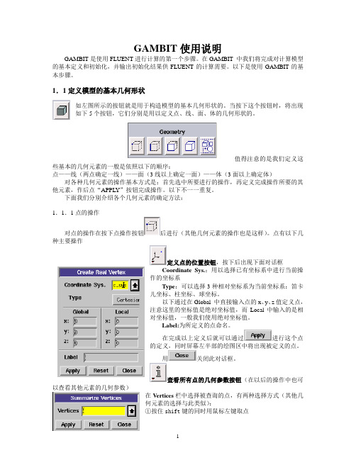
1.1定义模型的基本几何形状如左图所示的按钮就是用于构造模型的基本几何形状的。
当按下这个按钮时,将出现如下5个按钮,它们分别是用以定义点、线、面、体的几何形状的。
值得注意的是我们定义这些基本的几何元素的一般是依照以下的顺序:点——线(两点确定一线)——面(3线以上确定一面)——体(3面以上确定体)对各种几何元素的操作基本方式是:首先选中所要进行的操作,再定义完成操作所要的其他元素,作后点“APPLY”按钮完成操作。
以下不一一重复。
下面我们分别介绍各个几何元素的确定方法:1.1.1点的操作对点的操作在按下点操作按钮后进行(其他几何元素的操作也是这样)。
点有以下几种主要操作定义点的位置按钮,按下后出现下面对话框Coordinate Sys.:用以选择已有坐标系中进行当前操作的坐标系T ype:可以选择3种相对坐标系为当前坐标系:笛卡儿坐标、柱坐标、球坐标。
以下通过在Global 中直接输入点的x、y、z值定义点,注意这里的坐标值是绝对坐标值,而Local中输入的是相对坐标值,一般我们使用绝对坐标值。
Label:为所定义的点命名。
在完成以上定义后就可以通过进行这个点的定义,同时屏幕左半部的绘图区中将出现被定义的点。
用关闭此对话框。
查看所有点的几何参数按钮(在以后的操作中也可以查看其他元素的几何参数)在Vertices栏中选择被查询的点,有两种选择方式(其他几何元素的选择与此类似):①按住shift键的同时用鼠标左键取点②点按钮,选择查询点选择后进行“APPLY”完成操作,可在屏幕左下角Transcript框中看查询结果。
1.1.2线的操作线操作按钮下面介绍主要的几种线操作定义直线按钮定义直线的前提是有两个点,两点确定一条直线。
gambit 操作指南

GAMBIT 2.3Tutorial GuideMarch 2006Licensee acknowledges that use of Fluent, Inc.’s products can only provide an imprecise estimation of possible future performance and that additional testing and analysis, independent of the Licensor’s products, must be conducted before any product can be finally developed or commercially introduced. As a result, Licensee agrees that it will not rely upon the results of any usage of Fluent, Inc.’s products in determining the final design, composition, or structure of any product.© 2006 by Fluent, IncorporatedAll Rights Reserved. No part of this document may be reproduced or otherwise used in any form without express written permission from Fluent, Incorporated.Airpak, FIDAP, FLUENT, GAMBIT, Icepak, MixSim, and POLYFLOW are registered trademarks of Fluent, Inc.ImageMagick is © 1996 E.I. du Pont de Nemours and Co.All other products or name brands are trademarks of their respective holders.For GAMBIT Technical Support contact information, visit the Fluent, Inc. Web site at .Fluent, IncorporatedCenterra Resource Park10 Cavendish CourtLebanon, NH 03766iiiTABLE OF CONTENTS0. USING THIS TUTORIAL GUIDE.................................................... 0-1 0.1 What’s in This Guide .....................................................................................0-10.2 How to Use This Guide...................................................................................0-20.3 Font Conventions............................................................................................0-30.4 Using the Mouse..............................................................................................0-40.4.1 Menus and Forms .................................................................................0-40.4.2 Graphics Window.................................................................................0-40.5 GUI Components ............................................................................................0-80.5.1 Graphics Window.................................................................................0-90.5.2 Main Menu Bar ....................................................................................0-90.5.3 Operation Toolpad ...............................................................................0-90.5.4 Form Field..........................................................................................0-110.5.5 Global Control Toolpad .....................................................................0-120.5.6 Description Window ..........................................................................0-120.5.7 Transcript Window and Command Text Box ....................................0-121. CREATING AND MESHING BASIC GEOMETRY....................... 1-1 1.1 Prerequisites ....................................................................................................1-11.2 Problem Description.......................................................................................1-21.3 Strategy............................................................................................................1-31.4 Procedure.........................................................................................................1-4Step 1: Create a Brick....................................................................................1-5Step 2: Create an Elliptical Cylinder .............................................................1-8Step 3: Unite the Two Volumes ..................................................................1-10Step 4: Manipulate the Display ...................................................................1-12Step 5: Mesh the Volume ............................................................................1-14Step 6: Examine the Mesh...........................................................................1-16Step 7: Save the Session and Exit GAMBIT...............................................1-201.5 Summary .......................................................................................................1-212. MODELING A MIXING ELBOW (2-D)........................................... 2-1 2.1 Prerequisites ....................................................................................................2-12.2 Problem Description.......................................................................................2-22.3 Strategy............................................................................................................2-32.4 Procedure.........................................................................................................2-4Step 1: Select a Solver...................................................................................2-4Step 2: Create the Initial Vertices..................................................................2-5Step 3: Create Arcs for the Bend of the Mixing Elbow..............................2-10Step 4: Create Straight Edges......................................................................2-13Step 5: Create the Small Pipe for the Mixing Elbow ..................................2-15Step 6: Create Faces From Edges................................................................2-23Table of ContentsivStep 7: Specify the Node Distribution.........................................................2-26Step 8: Create Structured Meshes on Faces ................................................2-34Step 9: Set Boundary Types ........................................................................2-37Step 10: Export the Mesh and Save the Session .........................................2-412.5 Summary .......................................................................................................2-423. MODELING A THREE-PIPE INTERSECTION (3-D) ................... 3-1 3.1 Prerequisites ....................................................................................................3-13.2 Problem Description.......................................................................................3-23.3 Strategy............................................................................................................3-33.4 Procedure.........................................................................................................3-5Step 1: Select a Solver...................................................................................3-5Step 2: Create the Geometry..........................................................................3-5Step 3: Decompose the Geometry .................................................................3-9Step 4: Journal Files ....................................................................................3-19Step 5: Turn Off Automatic Smoothing of the Mesh..................................3-22Step 6: Apply Boundary Layers at Walls ....................................................3-24Step 7: Mesh the Sphere Octant Volume ....................................................3-28Step 8: Mesh the Pipe Volumes ..................................................................3-30Step 9: Examine the Quality of the Mesh....................................................3-41Step 10: Set Boundary Types ......................................................................3-443.5 Summary .......................................................................................................3-494. MODELING A COMBUSTION CHAMBER (3-D) ......................... 4-1 4.1 Prerequisites ....................................................................................................4-14.2 Problem Description.......................................................................................4-24.3 Strategy............................................................................................................4-34.4 Procedure.........................................................................................................4-6Step 1: Select a Solver...................................................................................4-6Step 2: Set the Default Interval Size for Meshing.........................................4-6Step 3: Create Two Cylinders .......................................................................4-8Step 4: Subtract the Small Cylinder From the Large Cylinder ....................4-12Step 5: Shade and Rotate the Display .........................................................4-14Step 6: Remove Three Quarters of the Cylindrical Volume........................4-15Step 7: Create the Chamber of the Burner ..................................................4-18Step 8: Blend the Edges of the Chamber.....................................................4-20Step 9: Decompose the Geometry ...............................................................4-23Step 10: Generate an Unstructured Hexahedral Mesh ................................4-36Step 11: Examine the Quality of the Mesh..................................................4-49Step 12: Set Boundary Types ......................................................................4-53Step 13: Export the Mesh and Save the Session .........................................4-584.5 Summary .......................................................................................................4-59Table of Contentsv5. SEDAN GEOMETRY—VIRTUAL CLEANUP ............................... 5-1 5.1 Prerequisites ....................................................................................................5-15.2 Problem Description.......................................................................................5-25.3 Strategy............................................................................................................5-35.4 Procedure.........................................................................................................5-4Step 1: Select a Solver...................................................................................5-4Step 2: Import the IGES File As-Is ...............................................................5-5Step 3: Reset and Import the IGES File Using Virtual Cleanup ...................5-9Step 4: Eliminate Very Short Edges ............................................................5-12Step 5: Automatically Connec t All Remaining “Duplicate” Edges ............5-16Step 6: Merge Faces ....................................................................................5-18Step 7: Mesh Faces on Car Body ................................................................5-23Step 8: Create a Brick Around the Car Body ..............................................5-26Step 9: Remove Unwanted Geometry .........................................................5-29Step 10: Create Straight Edges on the Symmetry Plane..............................5-30Step 11: Create Faces on the Symmetry Plane ............................................5-35Step 12: Create a Volume............................................................................5-41Step 13: Mesh the Edges .............................................................................5-43Step 14: Mesh the Volume ..........................................................................5-46Step 15: Examine the Volume Mesh...........................................................5-48Step 16: Set Boundary Types ......................................................................5-515.5 Summary .......................................................................................................5-586. SEDAN GEOMETRY—TOLERANT IMPORT.............................. 6-1 6.1 Prerequisites ....................................................................................................6-16.2 Problem Description.......................................................................................6-26.3 Strategy............................................................................................................6-36.4 Procedure.........................................................................................................6-4Step 1: Select a Solver...................................................................................6-4Step 2: Import the IGES File.........................................................................6-5Step 3: Merge Faces ......................................................................................6-8Step 4: Create a Brick Around the Car Body ..............................................6-13Step 5: Remove Unwanted Geometry .........................................................6-16Step 6: Create Straight Edges on the Symmetry Plane................................6-17Step 7: Create Faces on the Symmetry Plane ..............................................6-22Step 8: Create a Volume..............................................................................6-27Step 9: Apply Size Functions to Control Mesh Quality..............................6-29Step 10: Mesh the Volume ..........................................................................6-31Step 11: Examine the Volume Mesh...........................................................6-33Step 12: Set Boundary Types ......................................................................6-36Step 13: Export the Mesh and Save the Session .........................................6-426.5 Summary .......................................................................................................6-43 Table of Contentsvi7. MODELING FLOW IN A TANK...................................................... 7-1 7.1 Prerequisites ....................................................................................................7-17.2 Problem Description.......................................................................................7-27.3 Strategy............................................................................................................7-37.4 Procedure.........................................................................................................7-6Step 1: Select a Solver...................................................................................7-6Step 2: Set the Default Interval Size for Meshing.........................................7-6Step 3: Create Cylinders................................................................................7-8Step 4: Complete the Geometry Creation....................................................7-12Step 5: Decompose the Geometry ...............................................................7-16Step 6: Unite Some Parts of the Geometry..................................................7-23Step 7: Subtract the Remaining Parts of the Symmetry Plane.....................7-26Step 8: Split off Annulus Pipe to Make the Volumes Meshable.................7-31Step 9: Unite the Side Pipe..........................................................................7-40Step 10: Mesh the Edges .............................................................................7-42Step 11: Apply Boundary Layers ................................................................7-45Step 12: Mesh One of the Volumes ............................................................7-49Step 13: Mesh Some Faces..........................................................................7-52Step 14: Modify Mesh Settings on Some Faces..........................................7-58Step 15: Mesh the Volumes ........................................................................7-61Step 16: Examine the Volume Mesh...........................................................7-66Step 17: Set Zone Types and Export the Mesh ...........................................7-687.5 Summary .......................................................................................................7-738. BASIC TURBO MODEL WITH UNSTRUCTURED MESH.......... 8-1 8.1 Prerequisites ....................................................................................................8-18.2 Problem Description.......................................................................................8-28.3 Strategy............................................................................................................8-48.4 Procedure.........................................................................................................8-5 Step 1: Select a Solver...................................................................................8-5Step 2: Import a Turbo Data File...................................................................8-6Step 3: Create the Turbo Profile....................................................................8-8Step 4: Modify the Inlet and Outlet Vertex Locations ................................8-12Step 5: Create the Turbo Volume................................................................8-14Step 6: Define the Turbo Zones ..................................................................8-16Step 7: Apply 3-D Boundary Layers ...........................................................8-18Step 8: Mesh the Blade Cross-Section Edges .............................................8-22Step 9: Mesh the Center Spanwise Face .....................................................8-26Step 10: Mesh the Volumes ........................................................................8-28Step 11: Examine the Mesh.........................................................................8-30Step 12: Specify Zone Types.......................................................................8-35Step 13: Export the Mesh and Exit GAMBIT.............................................8-368.5 Summary .......................................................................................................8-37 Table of Contentsvii9. LOW-SPEED CENTRIFUGAL COMPRESSOR............................. 9-1 9.1 Prerequisites ....................................................................................................9-19.2 Problem Description.......................................................................................9-29.3 Strategy............................................................................................................9-39.4 Procedure.........................................................................................................9-4 Step 1: Select a Solver...................................................................................9-4Step 2: Import ACIS Geometry.....................................................................9-5Step 3: Create the Turbo Profile....................................................................9-8Step 4: Modify the Inlet and Outlet Vertex Locations ................................9-11Step 5: Create the Turbo Volume................................................................9-13Step 6: Define the Turbo Zones ..................................................................9-15Step 7: Adjust Edge Split Points .................................................................9-17Step 8: Decompose the Turbo Volume .......................................................9-20Step 9: Mesh the Volumes ..........................................................................9-21Step 10: Examine the Mesh.........................................................................9-23Step 11: Specify Zone Types.......................................................................9-27Step 12: Export the Mesh and Exit GAMBIT.............................................9-289.5 Summary .......................................................................................................9-2910. MIXED-FLOW PUMP IMPELLER.............................................. 10-1 10.1 Prerequisites ................................................................................................10-1 10.2 Problem Description...................................................................................10-210.3 Strategy........................................................................................................10-3 10.4 Procedure.....................................................................................................10-4 Step 1: Select a Solver.................................................................................10-4Step 2: Import a Turbo Data File.................................................................10-5Step 3: Create the Turbo Profile..................................................................10-8Step 4: Modify the Inlet and Outlet Vertex Locations ..............................10-11Step 5: Create the Turbo Volume..............................................................10-13Step 6: Define the Turbo Zones ................................................................10-15Step 7: Apply 3-D Boundary Layers .........................................................10-16Step 8: Mesh the Pressure and Suction Faces ...........................................10-19Step 9: Mesh the Volume ..........................................................................10-21Step 10: Examine the Mesh.......................................................................10-23Step 11: Specify or Check Zone Types .....................................................10-28Step 12: Export the Mesh and Exit GAMBIT...........................................10-3010.5 Summary ...................................................................................................10-3111. INDUSTRIAL DRILL BIT—STEP GEOMETRY....................... 11-1 11.1 Prerequisites ................................................................................................11-1 11.2 Problem Description...................................................................................11-211.3 Strategy........................................................................................................11-4 11.4 Procedure.....................................................................................................11-5 Table of ContentsviiiStep 1: Select a Solver.................................................................................11-5Step 2: Import a STEP File .........................................................................11-6Step 3: Merge Faces and Edges to Suppress Model Features .....................11-9Step 4: Use Cleanup Tools to Check and Clean Up Geometry.................11-11Step 5: Apply Size Functions to Control Mesh Quality............................11-18Step 6: Mesh the Volume ..........................................................................11-20Step 7: Examine the Volume Mesh...........................................................11-22Step 8: Export the Mesh and Exit GAMBIT.............................................11-2511.5 Summary ...................................................................................................11-2612. INDUSTRIAL DRILL BIT—DIRECT CAD IMPORT ............... 12-1 12.1 Prerequisites ................................................................................................12-1 12.2 Problem Description...................................................................................12-212.3 Strategy........................................................................................................12-4 12.4 Procedure.....................................................................................................12-5 Step 1: Start Pro/ENGINEER .....................................................................12-5Step 2: Start GAMBIT from within Pro/ENGINEER.................................12-6Step 3: Open the Part File ...........................................................................12-7Step 4: Display the GAMBIT User Interface..............................................12-8Step 5: Select the Solver..............................................................................12-9Step 6: Import the CAD Geometry............................................................12-10Step 7: Merge Faces and Edges to Suppress Model Features ...................12-12Step 8: Use Cleanup Tools to Check and Clean Up Geometry.................12-14Step 9: Apply Size Functions to Control Mesh Quality............................12-26Step 10: Mesh the Volume ........................................................................12-28Step 11: Examine the Volume Mesh.........................................................12-30Step 12: Export the Mesh and Close GAMBIT ........................................12-33Step 13: Exit Pro/ENGINEER and GAMBIT...........................................12-3512.5 Summary ...................................................................................................12-3613. CATALYTIC CONVERTER ......................................................... 13-1 13.1 Prerequisites ................................................................................................13-113.2 Problem Description...................................................................................13-213.3 Strategy........................................................................................................13-313.4 Procedure.....................................................................................................13-4Step 1: Select a Solver.................................................................................13-4Step 2: Import the IGES File.......................................................................13-5Step 3: Attempt to Heal the Geometry ........................................................13-8Step 4: Eliminate the Bad and Overlapping Faces ....................................13-11Step 5: Replace the Overlapping Face ......................................................13-13Step 6: Attempt Again to Heal the Geometry............................................13-15Step 7: Clean Up Holes in the Model........................................................13-17Step 8: Clean Up Short Edges ...................................................................13-21Step 9: Clean Up Sharp Angles.................................................................13-23Table of ContentsixStep 10: Clean Up Large Angles...............................................................13-26Step 11: Stitch the Faces to Create a Volume ...........................................13-29Step 12: Mesh the Large Circular Faces ...................................................13-30Step 13: Apply Size Functions to Control Mesh Quality..........................13-33Step 14: Mesh the Volume ........................................................................13-35Step 15: Examine the Volume Mesh.........................................................13-37Step 16: Export the Mesh and Save the Session .......................................13-4113.5 Summary ...................................................................................................13-4214. AIRPLANE GEOMETRY.............................................................. 14-1 14.1 Prerequisites ................................................................................................14-114.2 Problem Description...................................................................................14-214.3 Strategy........................................................................................................14-314.4 Procedure.....................................................................................................14-4Step 1: Select a Solver.................................................................................14-4Step 2: Import the STEP File ......................................................................14-5Step 3: Clean Up Duplicate Faces...............................................................14-8Step 4: View List of Duplicate Edges .......................................................14-11Step 5: Heal the Geometry ........................................................................14-12Step 6: Clean Up Holes .............................................................................14-13Step 7: Create a Brick around the Airplane Body.....................................14-17Step 8: Delete the Brick High-level Geometry..........................................14-20Step 9: Connect Faces on the Symmetry Plane .........................................14-21。
史上最详细的Gambit教程 不看后悔

Gambit建模简例教程2008年10月李宏刚本文通过建立一个简单的二维车身流场有限元模型,来说明应用Gambit建模的基本方法。
建模的方法不是唯一的,只有通过不断学习和实践才能更好的掌握。
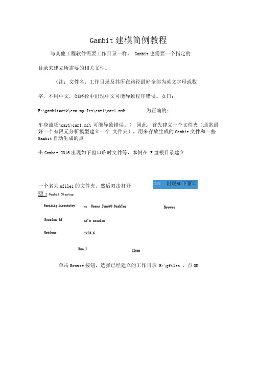
与其他工程软件需要工作目录一样,Gambit也需要一个指定的目录来建立所需要的相关文件。
(注:文件名、工作目录及其所在路径最好全部为英文字母或数字,不用中文,如路径中出现中文可能导致程序错误。
如:D:\gambitwork\examples\car1\car1.msh为正确的;D:\gambitwork\车身流场\car1\car1.msh可能导致错误。
)因此,首先建立一个文件夹(通常最好一个有限元分析模型建立一个文件夹),用来存放生成的Gambit文件和一些Gambit自动生成的临时文件等,本例在D盘根目录建立一个名为gfiles的文件夹。
然后启动Gambit。
如下图示。
点击Gambit 2.3.16出现如下窗口。
单击Browse按钮,选择已经建立的工作目录d:\gfiles,点OK。
在Session Id栏中输入建立的工程文件名,我们这里输入car1。
(以后再次对该文件进行编辑时,在右侧的下拉列表中直接选取该文件即可,如遇到无法打开的情况,可将目录中的*.lok文件删除后再试。
)单击Run 后进入Gambit 主界面,如下。
一、Gambit 的操作界面如上图所示,Gambit 用户界面可分为7个部分,分别为:菜单栏、视图、命令面板、命令显示窗、命令解释窗、命令输入窗和视图控制面板。
文件栏文件栏位于操作界面的上方,其最常用的功能就是File 命令下的New 、Open 、Save 、Save as 和Export 等命令。
这些命令的使用和一般的软件一样。
Gambit 可识别的文件后缀为.dbs ,而要将Gambit 中建立的网格模型调入Fluent 使用,则需要将其输出为.msh 文件(file/export)。
Gambit使用教程

三维建模相对于二维建模而言,三维建模与二维建模的思路有着较大的区别。
二维建模主要遵循点、线、面的原则,而三维建模则更象搭积木一样,由不同的三维基本造型拼凑而成,因此在建模的过程中更多的用到了布尔运算及Autocad等其他的建模辅助工具。
三视图的使用在建立三维图形的时候,使用三视图有利于我们更好的理解图形。
图30显示的是Gambit的视图控制面板。
图30在当前状况下,四个视图都是激活的(在Active栏中,显示红色),这时视图控制面板中的十个命令将同时作用于四个视图。
在创建三维图形之前,我们要做的第一项工作就是要将Gambit的四个视图设置为顶视图、前视图、左视图和透视图。
1.用鼠标单击Active右边的后三个视图,取消对它们的激活,激活取消后呈灰色(见图31)。
图312.用鼠标右键单击视图控制面板中的坐标按钮,弹出一组坐标系(见图32)。
3.选择,则左上视图变成顶视图。
如法炮制,设置其他视图(见图33)。
4.单击控制面板中的,也可将视图设成三视图。
图32图33基本三维模型的建立在Gambit控制面板中单击按钮,在Volume中用鼠标右键单击,弹出一组按钮(见图34),表示Gambit所能创建的基本三维几何体,主要有长方体、圆柱体等。
图34布尔运算的基本概念典型的布尔运算包括并、交、减。
并:将两个物体并成一个物体(两个物体的并集)交:两个物体的交集减:A物体减去B物体下面用一个简单的例子来说明基本三维几何体的创建和布尔运算的运用1.单击按钮,输入参数创建一个高60,半径6的圆柱体(见图35)。
在Axial Loaction栏中选取Positive X,使得圆柱体的法线指向x方向。
在Gambit中创建的几何体,其基点都在坐标系的原点(见图36)。
如果创建的几何体过大,在视图中无法显示全图,或者太小,无法分辨,单击按钮即可。
图35图362.为了能够更好的观察三维几何体,可以用鼠标拖动四个视图中央的小方块,改变四个视图的大小(见图37)。
GAMBIT实例教程
L1 -> L2 -> L3
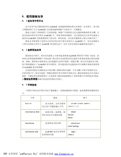
0. 3 字体协定
下面的字体在这手册中代表了数ห้องสมุดไป่ตู้输入、表格标题和命令按钮、选项和模型化物体的名 字。
字体
描述
例子
Courier
命令说明、文件名称和
volume create sphere
其它用户从键盘输入字符 GAMBIT.ini
Arial Narrow, Bold
按钮名称、选择器、域 和在 GUI 中出现的表格
0. 4 鼠标用法
GAMBIT GUI 是为用三键鼠标而设计的。每个鼠标按钮的功能根据鼠标是在菜单表格还 是在图形窗口上操作而不同。一些在图形窗口上鼠标操作是和键盘同时操作的。 0.4.1 菜单表格
GAMBIT 菜单和表格的鼠标操作只要求左右键而且不涉及任何键盘操作。其中大部分只 要用左键操作。右键用来打开涉及到工具板上命令按钮的菜单,在一些表格上包含文本窗口, 右键打开选项的隐藏菜单,比如在 GAMBIT 用户向导的 3.2.8 章节中的“下拉列表用法”。 0.4.2 图形窗口
PDF 文件使用 "pdfFactory Pro" 试用版本创建
当它被按下后在它顶部和左边有黑色边。GEOMETRY(几何体)命令按钮
在操作工
具板的顶部如图 0-1 是一个按下的按钮的例子。按钮没按下时按钮的底边和右边是黑色的。
GAMBIT用户手册_2_启动GAMBIT
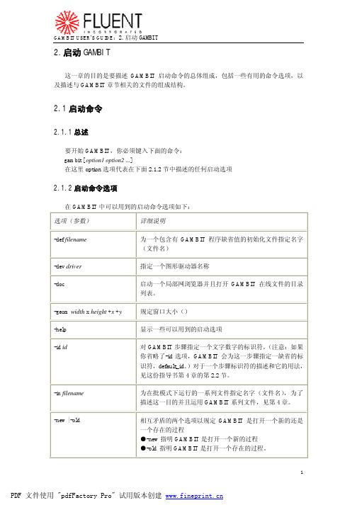
2.2.2 目录结构
GAMBIT 采用四种类型的地址去组成片段数据文件和其它与 GAMBIT 操作相关的文件。下
2
PDF 文件使用 "pdfFactory Pro" 试用版本创建
GAMBIT USER’S GUIDE:2.启动 GAMBIT
面的表格描述了这四种地址每一个的类型、位置和内容:
进程文件位置/名称
scratchname/GAMBIT.6789/jou scratchname/GAMBIT.6789/dbs scratchname/GAMBIT.6789/trn
复制文件的位置/名称
mymodel/model1.jou mymodel/model1.dbs mymodel/model1.trn
名称
jou
标题
日志
格式
文本
内容
片段中的几何体、网格、区域和执行的工具命令的连续 列表 片段中 GAMBIT transcript 窗口中的一系列信息 包括几何体、网格、展示、缺省和以及模型有关的日志 消息的二进制数据库
trn dbs
文本 数据库
文本 二进制
除上面列的三个数据文件之外,GAMBIT 生成一个“锁定”文件,命名为“id.lok” ,在 这儿 id 代表片段标识符。 这个锁定文件的目的是要把当前 GAMBIT 片断的过程数据琐住以使 数据文件不能被任何并行的 GAMBIT 片断访问和/或修改。
Scratch
用户指定
Working
Scratch 地址的辅地 址(见下文)
Home,source 和 scratch 目录 source 和 scratch 地址的缺省位置是统一的, GAMBIT 开始的地方。 在 你可以通过 GAMBIT edit defaults 栏来改变 Home,source 和 scratch 地址的缺省位置。关于 edit defaults 栏的详述,见本指导书的第四章。 Working 目录 Working 地址是 Scratch 地址的辅地址。它的名字包括标识符 “GAMBIT”附加一个程序 号。例如,如果你开始 GAMBIT 并 scratch 地址名为“users1”程序号是“1234” ,GAMBIT 把片段文件-即 jou,dbs 和 lok-定位在一个名为 users1/gambit.12345 的地址里。
gambit中文指导帮助

第一章介绍本向导的目的在于分类和描述通过GAMBIT GUI有效的操作。
本向导的逻辑结构遵从Operation工具框和与之相关的子工具框。
也就是说,章节、部分和子部分的组织反应了GUI 上命令按钮的层次。
例如,第二章、第三章、第四章和第五章分别阐述了与命令按钮Geometry、Mesh、Zones和Tools相关的操作,它反应了这些命令按钮在Operation工具框中显示的顺序(如图1所示)。
图1-1:Operation工具框类似的,Blend Volumes操作的详细说明在Volume Boolean操作说明之后,因为在Geometry/ Volume子工具框中它的命令按钮工具框位于Boolean命令按钮的右边(如图1-2所示)。
图1-2:Geometry/Volume子工具框1.1格式和字体的规定GAMBIT User's Guide的第一章阐述了用于整个向导的基本格式和字体的规定。
为了方便起见,在此再次说明格式和字体的规定。
1.1.1格式的规定本向导使用两种标准格式。
•图形格式•版面格式图形格式决定了在GAMBIT GUI中用于代表控制单元和命令按钮的符号类型。
版面格式决定了GAMBIT设定窗口的描述结构。
图形格式使用了两种基本类型的用户界面组件。
•控制单元•工具框命令按钮以下的部分详细说明用于整个文件中的规定来阐述上面列举的组件。
控制单元GAMBIT GUI使用诸如命令按钮、选择按钮和文本框等控制单元来使用户进行诸如执行动作、选择选项设置和输入字母数据等操作。
用于本向导的图形格式规定提供了如下的GAMBIT GUI控制单元。
控制单元示例图形格式功能命令按钮Command执行按钮标题所指示的命令。
选择按钮Option 1从互斥选项菜单中选择。
Option 2…文本框Value从键盘上接受字符数据。
窗口标题Heading:指定按钮和选项组的一般功能单选按钮Option从显示的互斥选项菜单中选择。
gambit使用说明书(附范例)
适用类型
方法
Quad
Tri
Quad/Tri
Map
Submap
Pave
Tri Primitive
Wedge Primitive
表2
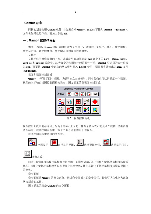
下面仍然以二维轴对称自由射流的网格划分为例,来介绍各种网格的生成。
1.单击命令面板中的 按钮(Mesh Face),进入面的网格创建命令面板(见图25)。
图25
2.选择视图中的面,系统中默认的网格点的类型为四边形结构网格。单击Apply按钮,观察网格的生成(见图26)。
视图控制面板中常用的命令有:
全图显示、 选择显示视图、 选择视图坐标、 选择显示项目、 渲染方式。
同时,我们还可以使用鼠标来控制视图中的模型显示。其中按住左键拖曳鼠标可以旋转视图,按住中键拖动鼠标则可以在视图中移动物体,按住右键上下拖动鼠标可以缩放视图中的物体。
命令面板
命令面板是Gambit的核心部分,通过命令面板上的命令图标,我们可以完成绝大部分网格划分的工作。
图26
3.在命令面板的Type中选择网格类型为Pave,单击Apply按钮,观察网格的生成(见图27)。
图27
4.选择Element类型为Tri,单击Apply按钮,观察网格的生成(见图28)。
图28
三.
在Gambit中,我们可以先定义好各个边界条件的类型,具体的边界条件取值在Fluent中确定。
1.在菜单栏中选择Fluent/Fluent5。这个步骤是不可缺少的,它相当于给Gambit定义了一个环境变量,设置完之后,定义的边界条件类型和Fluent5中的边界类型相对应。
命令显示窗和命令输入栏
命令显示窗和命令输入栏位于Gambit的左下方(如图4所示)。
完整版Gambit详细操作步骤1
Gambit 建模简例教程与其他工程软件需要工作目录一样, Gambit 也需要一个指定的 目录来建立所需要的相关文件。
(注:文件名、工作目录及其所在路径最好全部为英文字母或数字,不用中文,如路径中出现中文可能导致程序错误。
女口:E:\gambitwork\exa mp Ies\car1\car1.msh为正确的;车身流场\car1\car1.msh 可能导致错误。
) 因此,首先建立一个文件夹(通常最好一个有限元分析模型建立一个 文件夹),用来存放生成的Gambit 文件和一些Gambit 自动生成的点击Gambit 2316出现如下窗口临时文件等,本例在 E 盘根目录建立堕I Gambit StartupOptionsRun I单击Browse 按钮,选择已经建立的工作目录 E:\gfiles ,点0K一个名为gfiles 的文件夹。
然后双击打开Wcridiig Directc?ry|c ;Users JenoVO DeskTopBrowseSession Idnt'w session -r?4 6& Garr hit Startup Workin-g D r^clDrySession Id OptjMS|C\UE«-s'J#novfivD#ikiop Bicrw-aeBelection-T2.4.(iRjjn Cose2J b纸二IMF 斤I :□电翻二I简用二I 口确试OKCaiielD R V6*:在Session Id栏中输入建立的工程文件名,我们这里输入carl。
03 Gambit StartupUntieing Duecton-Session Id carlBrews e OpUfln.5-r24 6E AHI Close(以后再次对该文件进行编辑时,在Sessi on Id栏右侧的下拉列表中直接选取该文件即可,如遇到无法打开的情况,可将目录中的*lok文件删除后再试。
GAMBIT使用说明

GAMBIT使用说明GAMBIT使用说明GAMBIT是使用FLUENT进行计算的第一个步骤。
在GAMBIT 中我们将完成对计算模型的基本定义和初始化,并输出初始化结果供FLUENT的计算需要。
以下是使用GAMBIT的基本步骤。
1.1定义模型的基本几何形状如左图所示的按钮就是用于构造模型的基本几何形状的。
当按下这个按钮时,将出现如下5个按钮,它们分别是用以定义点、线、面、体的几何形状的。
值得注意的是我们定义这些基本的几何元素的一般是依照以下的顺序:点——线(两点确定一线)——面(3线以上确定一面)——体(3面以上确定体)对各种几何元素的操作基本方式是:首先选中所要进行的操作,再定义完成操作所要的其他元素,作后点“APPLY”按钮完成操作。
以下不一一重复。
下面我们分别介绍各个几何元素的确定方法:1.1.1点的操作对点的操作在按下点操作按钮后进行(其他几何元素的操作也是这样)。
点有以下几种主要操作定义点的位置按钮,按下后出现下面对话框Coordinate Sys.:用以选择已有坐标系中进行当前操作的坐标系T ype:可以选择3种相对坐标系为当前坐标系:笛卡儿坐标、柱坐标、球坐标。
以下通过在Global 中直接输入点的x、y、z值定义点,注意这里的坐标值是绝对坐标值,而Local中输入的是相对坐标值,一般我们使用绝对坐标值。
Label:为所定义的点命名。
在完成以上定义后就可以通过进行这个点的定义,同时屏幕左半部的绘图区中将出现被定义的点。
用关闭此对话框。
查看所有点的几何参数按钮(在以后的操作中也可以查看其他元素的几何参数)在Vertices栏中选择被查询的点,有两种选择方式(其他几何元素的选择与此类似):①按住shift键的同时用鼠标左键取点②点按钮,选择查询点选择后进行“APPLY”完成操作,可在屏幕左下角Transcript框中看查询结果。
1.1.2线的操作线操作按钮下面介绍主要的几种线操作定义直线按钮定义直线的前提是有两个点,两点确定一条直线。
Gambit使用教程中文版
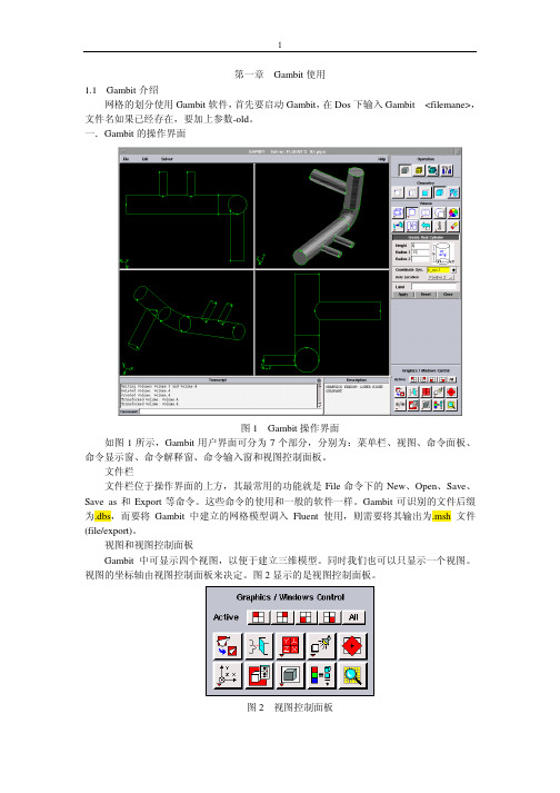
第一章Gambit使用1.1Gambit介绍网格的划分使用Gambit软件,首先要启动Gambit,在Dos下输入Gambit<filemane>,文件名如果已经存在,要加上参数-old。
一.Gambit的操作界面图1Gambit操作界面如图1所示,Gambit用户界面可分为7个部分,分别为:菜单栏、视图、命令面板、命令显示窗、命令解释窗、命令输入窗和视图控制面板。
文件栏文件栏位于操作界面的上方,其最常用的功能就是File命令下的New、Open、Save、Save as和Export等命令。
这些命令的使用和一般的软件一样。
Gambit可识别的文件后缀为.dbs,而要将Gambit中建立的网格模型调入Fluent使用,则需要将其输出为.msh文件(file/export)。
视图和视图控制面板Gambit中可显示四个视图,以便于建立三维模型。
同时我们也可以只显示一个视图。
视图的坐标轴由视图控制面板来决定。
图2显示的是视图控制面板。
图2视图控制面板视图控制面板中的命令可分为两个部分,上面的一排四个图标表示的是四个视图,当激活视图图标时,视图控制面板中下方十个命令才会作用于该视图。
视图控制面板中常用的命令有:渲染方式。
同时,我们还可以使用鼠标来控制视图中的模型显示。
其中按住左键拖曳鼠标可以旋转视图,按住中键拖动鼠标则可以在视图中移动物体,按住右键上下拖动鼠标可以缩放视图中的物体。
命令面板命令面板是Gambit的核心部分,通过命令面板上的命令图标,我们可以完成绝大部分网格划分的工作。
图3显示的就是Gambit的命令面板。
图3Gambit的命令面板从命令面板中我们就可以看出,网格划分的工作可分为三个步骤:一是建立模型,二是划分网格,三是定义边界。
这三个部分分别对应着Operation区域中的前三个命令按钮Geometry(几何体)、mesh(网格)和Zones(区域)。
Operation中的第四个命令按钮Tools 则是用来定义视图中的坐标系统,一般取默认值。
