SMS-1508-2-R, 规格书,Datasheet 资料
1241.1608;中文规格书,Datasheet资料
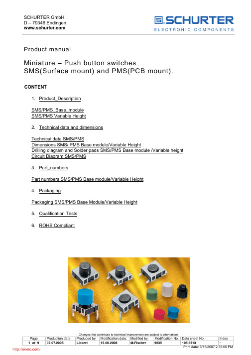
Product manualMiniature – Push button switchesSMS(Surface mount) and PMS(PCB mount). CONTENT1. Product_DescriptionSMS/PMS_Base_moduleHeightVariableSMS/PMS2. Technical data and dimensionsSMS/PMSTechnicaldataDimensions SMS/ PMS Base module/Variable HeightDrilling diagram and Solder pads SMS/PMS Base module /Variable height Circuit Diagram SMS/PMS3. Part_numbersPart numbers SMS/PMS Base module/Variable Height4. PackagingPackaging SMS/PMS Base Module/Variable Height5. Qualification Tests6. ROHS Compliant1 Description1.1 SMS/PMS Base moduleMiniature push button switches with a low height of 4,55 - 4,95 mm for surface mounting (SMS) and PCBmounting (PMS).The SMS has large flat surfaces on the top side as well as on the other sides, which are also parallel to each other. This makes the SMS a perfect switch for automatic mounting.The SMS switch is suitable for the SMD soldering process "IR-Reflow".The switch comes with the SMD-leads "Gullwing and J". With J-leads the switch can be lined up with a spacing of 1/2" in one coordinate direction, and with > 13,5 mm in the other coordinate direction. With Gullwing-leads, the switch can be arranged with a spacing of 1/2" in one coordinate direction, and in the other coordinate direction with > 17,5 mm.A minimum spacing of 1/2" to 15 mm is necessary for the PCB version.Basically, the SMS and PMS come in two basic versions concerning the degree of protection. Available are IP 40 and IP 67. According to the degree of protection the IP 40 version is not proof against fluxing and washing, whereas the IP 67 version is. Consequently, the IP 67 version can be exposed to the specified soldering and cleaning processes.The miniature push button switches feature a very good tactile response with an actuation force of about 2N. SMS and PMS are also available with an elongated actuator. These variants serve as base modules for the SMS/PMS variable height version.1.2 SMS/PMS Variable HeightThe variable height SMS/PMS consists of the SMS/PMS base module with elongated actuator and a slip-on button with eight variable heights.The PMS will be supplied with a mounted button. The button for the SMS has to be ordered separately. After soldering, the button must be put on the base module with elongated actuator.Heights between 8,5 mm and 13,75 mm for the SMS and 8,35 mm and 13,60 mm for the PMS are available. Depending on the base module being used, degree of protection for the variable height SMS/PMS is IP 40 or IP 67.2 Data and dimensional drawings2.1 Technical Data SMS/PMS Base module/Variable HeightElectrical data: IP40IP67 Contact material Gold ; Gold/Silver (1) GoldSwitching voltage max. 30V AC/ 42V DC 30V AC/ 42V DCSwitching current max. 50 mA 50 mARated breaking capacity 12 V/10 mA 12 V/10 mALifetime (at 12V/10mA) >1 x 10⁶cycles >1 x 10⁶cyclesLifetime (at 24V/80mA) - ; >1x10⁵ (1) -Initial contact resistance new (IEC 512-2 mV-method) <50 mOhm <50 mOhmInitial contact resistance after 1 x 10⁶ cycles <150 mOhm <150 mOhmInsulation resistance (IEC 512-2) > 1x 10⁸ Ohm > 1x 10⁸ OhmContact bounce time typ. 0,15 ms typ. 0,15 msIP67 Mechanical data: IP40Actuating force 1,8±0,4 N 2,2±0,4 NActuating travel 0,35±0,1 mm 0,35±0,1 mmMechanical strength (force axial, load 1 min.) max. 100 N max. 100 NLifetime(IEC 512-5. Test 9a. Actuating force 5N) >1x 10⁶ cycles >1x 10⁶Soldering data:SMS PMSIP40/IP67 IP40/IP67Soldering method IR Reflow Wave solderingSoldering heat resistance 245 °C/5sec. 248,5 °C/1sec(1)Recommended IR-Reflow Profile for SMSTolerance for Temperature settings T +0°C (according to JEDEC J-STD-020C, July 2004) Used Solder: Omnix O338 (Sn95.5%/Ag4%/Cu0.5%), Alpha Metals Loetsysteme GmbHRecommended Wave Soldering Profile for PMSWave Soldering Equipment: ERSA EMS 3300 Throughput speed: 1m / minSolder type:Sn100C from Nihon Superior (Balver-Solder) Flux material:AW30 Fa. Otto Adjustments Heating ZonesUpper Zone : 280 °C 300 °CLower Zone:450°C500 °C 560 °COther data:SMS PMS SMS PMSIP40 IP40 IP67 IP67Operating temperature(°C) -40 to 85 -40 to 85 -40 to 85 -40 to 85Storage temperature(°C) -40 to 85 -40 to 85 -40 to 85 -40 to 85Degree of protection (DIN 40050) IP40 IP40 IP67 IP67Cleaning agent proofZestronZestronapplied test agent 3) ZestronZestronFlux proof 1) _______ _______ given givenWash proof 2)______________given given1) Visual inspection of switch chamber after immersion in coliophonium solution flux for 3 seconds.2) Inspection of switch chamber after washing process3) CKW and FCKW free mix made of water soluable GlykoletherMechanical data:SMS/PMS SMS/PMS Component Flammabilityrating IP40IP67Socket UL94 V-0 Thermoplast (PA 4.6) Thermoplast (PA 4.6)(PPS) Actuator UL94 V-0 Thermoplast(PPS) ThermoplastCover plate X12 Cr Ni 17 7 X12 Cr Ni 17 7Sealing membrane UL94 HB ________ VMQ Elongated button UL94 V-2 Thermoplast (PC) Thermoplast(PC)Electrical data(material): SMS/PMSSMS/PMSIP40 IP67 Snap dome X12 CrNi 17 7 gold plated on contact sideContacts CuZn37with Ni/Au coated; with Ag coated (1)with Sn coatedTerminals(leads) CuZn372.2 Dimensions SMS/PMS Base module/variable heightSMS Gullwing Base module SMS J-lead Base module PMS PCB Base moduleSMS Gullwing Variable height SMS J-lead Variable height PMS PCB Variable heightSMS Gullwing and J lead with elongated button PMS PCB with elongated buttonGullwing J-AnschlussTotal height information: See point 3.1, Part numbers SMS und PMS Variable height, SMS elongated button must be ordered separately.2.3 Drilling diagram and Solder pads SMS/PMS Base module/variable height Gullwing lead J-lead2.4 Circuit Diagram SMS/PMS3 Part numbers3.1 Part numbers SMS/PMS Base module/Variable HeightPart-Nr. Base moduleType IP40 IP67 Gullwing lead 1241.1600.XX 1241.1606.XX J-lead 1241.1601.XX 1241.1607.XX Through hole lead 1241.1602 1241.1608Part-Nr. Elongated base moduleType IP40 IP67 Gullwing lead 1241.1612.XX 1241.1618.XX J-lead 1241.1613.XX 1241.1619.XX Through hole lead 1241.1614 1241.1620Ordering example______________ Base module_______________________1241.XXXX.XXIndex 11 loose in boxesIndex 23 Blister tapePart-Nr. Variable height PMSHeight in mm IP 40 IP67 Color8,35 1241.1624.11241.1625.1 Yellow1241.1625.2 Orange 9,10 1241.1624.29,85 1241.1624.31241.1625.3 Red1241.1625.4 Blue 10,60 1241.1624.41241.1625.5 Green 11,35 1241.1624.512,10 1241.1624.61241.1625.6 Grey1241.1625.7 Black 12,85 1241.1624.71241.1625.8 White 13,60 1241.1624.8Part-Nr. Elongated buttons for SMSSwitch height SMS with mountedPart-Nr. Color buttons in mm8,50 0862.8101 Yellow9,25 0862.8102 Orange10,00 0862.8103 Red10,75 0862.8104 Blue11,50 0862.8105 Green12,25 0862.8106 Grey13,00 0862.8107 Black13,75 0862.8108 White4 Packaging4.1 Packaging SMS/PMS Base module/Variable Heightloose in boxes SMS/PMS - Index 11 for SMS 100 pieces tape and reel for SMS base module - Index 23 700 pieces tape and reel for SMS elonged. base module -Index 23 450 pieces5 Qualification Tests6 ROHS Compliant分销商库存信息: SCHURTER 1241.1608。
SSG 500_CN
是
是
是
是
是
是
是
是
100,000 以上
POP3,SMTP,HTTP,IMAP,FTP
是
是
是
是
是
是
是
是
是
是
是
是
是
是
VoIP 安全性
H.323. ALG
是
是
SIP ALG
是
是
SCCP ALG
是
是
MGCP ALG
是
是
用于 SIP 和 H.323/MGCP/SCCP
的 NAT
是
是
SSG 550
SSG 520
VPN
是 是 12 个 是 是 12 个 是
是 是 12 个 是 是 12 个 是
流量管理(QoS) 带宽保证 带宽限制 基于优先级的带宽使用 DiffServ 标记
是 是,逐物理接口
是 是,逐策略
是 是,逐物理接口
是 是,逐策略
系统管理 WebUI(HTTP 和 HTTPS) 命令行接口(控制台) 命令行接口(远程登录) 命令行接口(SSH) NetScreen-Security Manager 通过任何接口上的 VPN 隧道提供全部管理 SNMP 全面定制的 MIB 快速部署
Page 1 Datasheet
Juniper 网络公司 500 系列安全业务网关
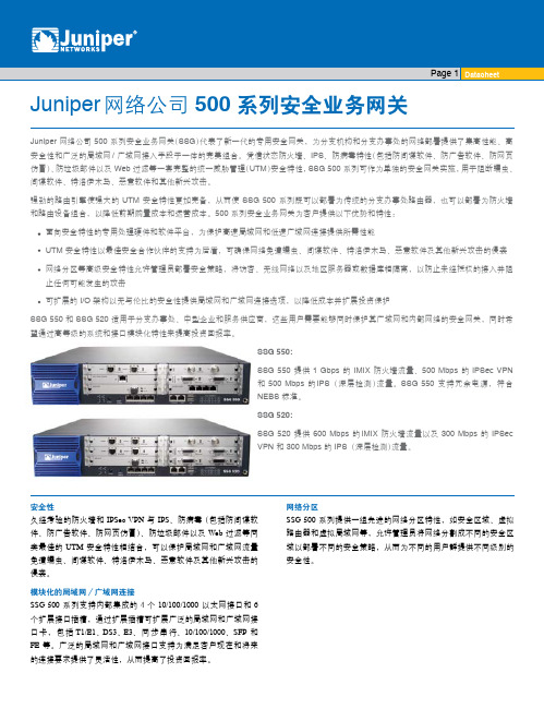
Juniper 网络公司 500 系列安全业务网关(SSG)代表了新一代的专用安全网关,为分支机构和分支办事处的网络部署提供了集高性能、高 安全性和广泛的局域网 / 广域网接入手段于一体的完美组合。凭借状态防火墙、IPS、防病毒特性(包括防间谍软件、防广告软件、防网页 仿冒)、防垃圾邮件以及 Web 过滤等一套完整的统一威胁管理(UTM)安全特性,SSG 500 系列可作为单独的安全网关实施,用于阻断蠕虫、 间谍软件、特洛伊木马、恶意软件和其他新兴攻击。
SMS12中文资料

u EIAJ SOT23-6L package u Molding compound flammability rating: UL 94V-0 u Marking : Marking Code u Packaging : Tape and Reel per EIA 481
Applications
u Cell phone Handsets and Accessories u Microprocessor Based Equipment u Personal Digital Assistants (PDAs) and Pagers u Desktops PC and Servers u Notebook, Laptop, and Palmtop Computers u Portable Instrumentation u Peripherals u MP3 Players u Cordless Phones
Symbol Ppk IPP VPP TL TJ TSTG
Value 350 24 >25 260 (10 sec.) -55 to +125 -55 to +150
Units Watts
A kV °C °C °C
Electrical Characteristics
SMS05
Parameter
Symbol
PROTECTION PRODUCTS Applications Information
Device Connection for Protection of Four Data Lines The SMSxx is designed to protect up to four unidirectional data lines. The device is connected as follows:
3590S-2-502L;3590S-2-102L;3590S-2-103L;3590S-2-203L;3590S-1-502L;中文规格书,Datasheet资料

Specifi cations are subject to change without notice.Customers should verify actual device performance in their specifi c applications.*RoHS Directive 2002/95/EC Jan. 27, 2003 including annex and RoHS Recast 2011/65/EU June 8, 2011.Stop Strength..............................................................................................................................................................................45 N-cm (64 oz.-in.) minimum Mechanical Angle ...........................................................................................................................................................................................3600 ° +10 °, -0 °Torque (Starting & Running) ................................................................................................................................0.35 N-cm (0.5 oz.-in.) maximum (unsealed) 1.1 N-cm (1.5 oz.-in.) maximum (sealed) Mounting ..............................................................................................................................................................................55-80 N-cm (5-7 lb.-in.) (plastic) 90-113 N-cm (8-10 in.-lb.) (metal)Shaft Runout......................................................................................................................................................................................0.13 mm (0.005 in.) teral Runout ...................................................................................................................................................................................0.20 mm (0.008 in.) T.I.R.Shaft End Play ...................................................................................................................................................................................0.25 mm (0.010 in.) T.I.R.Shaft Radial Play ...............................................................................................................................................................................0.13 mm (0.005 in.) T.I.R.Pilot Diameter Runout .......................................................................................................................................................................0.08 mm (0.003 in.) T.I.R.Backlash ............................................................................................................................................................................................................1.0 ° maximum Weight ........................................................................................................................................................................................................Approximately 19 G Terminals ................................................................................................................................................................................................Solder lugs or PC pins Soldering ConditionManual Soldering...........................................................96.5Sn/3.0Ag/0.5Cu solid wire or no-clean rosin cored wire; 370 °C (700 °F) max. for 3 seconds Wave Soldering ...................................................................................96.5Sn/3.0Ag/0.5Cu solder with no-clean fl ux; 260 °C (500 °F) max. for 5 seconds Wash processes .......................................................................................................................................................................................Not recommended Marking .....................................Manufacturer’s name and part number, resistance value and tolerance, linearity tolerance, wiring diagram, and date code.Ganging (Multiple Section Potentiometers) ......................................................................................................................................................1 cup maximum Hardware ............................................................................................................One lockwasher and one mounting nut is shipped with each potentiometer.NOTE: For Anti-rotation pin add 91 after confi guration dash number. Example: -2 becomes -291 to add AR pin.1At room ambient: +25 °C nominal and 50 % relative humidity nominal, except as noted. 2Consult manufacturer for complete specifi cation details for resistances below 1k ohms.BOLDFACE LISTINGS ARE IN STOCK AND READILY AVAILABLETHROUGH DISTRIBUTION. FOR OTHER OPTIONS CONSULT FACTORY.ROHS IDENTIFIER: L = COMPLIANTRecommended Part Numbers(Printed Circuit)(Solder Lug)(Solder Lug)Resistance (Ω)Resolution (%)3590P-2-102L 3590S-2-102L 3590S-1-102L 1,000.0293590P-2-202L 3590S-2-202L 3590S-1-202L 2,000.0233590P-2-502L 3590S-2-502L 3590S-1-502L 5,000.0253590P-2-103L 3590S-2-103L 3590S-1-103L 10,000.0203590P-2-203L 3590S-2-203L 3590S-1-203L 20,000.0193590P-2-503L 3590S-2-503L 3590S-1-503L 50,000.0133590P-2-104L3590S-2-104L3590S-1-104L100,000.009*Ro H S C O MP L I A N T/Panel Thickness Dimensions(For Bushing Mount Only)1.60 +.08/-.03(.063 +.003/-.001)DIA.ANTI-ROTATION PINAnti-rotation pin hole is shown at six o'clockposition for reference only. The actual location isdetermined by the customer's application. Referto the front view of the potentiometer to see thelocation of the optional A/R pin.Panel thickness and hole diameters arerecommended for best fit. However, customersmay adjust the dimensions to suit their specificapplication.Product DimensionsSpecifi cations are subject to change without notice.Customers should verify actual device performance in their specifi c applications.REV. 06/12 MOUNTING SURFACE-2, -4, -6, -8 Confi gurations-1, -3, -5, -7 Confi gurationsRecommended PCB LayoutHOLE DIAMETER5.08(.200)5.08(.200)6.99(.275)SchematicTOLERANCES: EXCEPT WHERE NOTED.508 .127DECIMALS: .XX ±(.02),.XXX ±(.005)FRACTIONS: ±1/64MMDIMENSIONS:(IN.)Shaft & Bushing Confi gurations(Bushing - DxL, Shaft - D):(-1) Plastic Bushing (3/8 ” x 5/16 ”)and Shaft (.2480 + .001, - .002)(-2) Metal Bushing (3/8 ” x 5/16 ”)and Shaft (.2497 + .0000, - .0009)(-3) Sealed, Plastic Bushing (3/8 ” x 5/16 ”)and Shaft (.2480 + .001, - .002)(-4) Sealed, Metal Bushing (3/8 ” x 5/16 ”)and Shaft (.2497 + .0000, - .0009)(-5) Metric, Plastic Bushing (9 mm x 7.94 mm)and Shaft (6 mm + 0, - .076 mm)(-6) Metric, Metal Bushing (9 mm x 7.94 mm)and Shaft (6 mm + 0, - .023 mm)(-7) Metric, Sealed, Plastic Bushing (9 mm x7.94 mm) and Shaft (6 mm + 0, - .076 mm)(-8) Metric, Sealed, Metal Bushing (9 mm x7.94 mm) and Shaft (6 mm + 0, - .023 mm)Terminal Styles“P” Terminal Style“S” Terminal Style/分销商库存信息:BOURNS3590S-2-502L3590S-2-102L3590S-2-103L 3590S-2-203L3590S-1-502L3590S-2-104L 3590S-1-203L3590S-2-501L3590S-2-202L 3590S-1-503L3590S-2-503L3590S-1-104L 3590S-291-102L3590S-291-203L3590S-291-502L 3590S-1-201L3590S-1-501L3590S-2-101L 3590S-2-201L3590P-1-102L3590P-1-103L 3590P-1-201L3590P-1-502L3590S-1-102L 3590S-1-103L3590S-2-252L3590P-291-501L 3590P-2-102L3590P-2-201L3590P-2-203L 3590P-2-502L3590S-1-202L3590S-6-102L 3590S-6-201L3590S-6-202L3590S-6-203L 3590S-6-501L3590P-1-104L3590S-6-502L 3590S-4-102L3590S-4-103L3590S-4-202L 3590S-4-203L3590S-4-502L3590S-8-102L 3590S-8-103L3590S-8-202L3590P-2-104L 3590P-4-103L3590P-4-202L3590S-6-503L 3590S-6-104L3590S-4-104L3590P-4-503L 3590P-4-104L3590S-2-5023590S-1-102 3590S-1-1033590S-1-1043590S-1-203 3590S-1-5023590S-1-5033590S-2-102 3590S-2-1033590S-2-1043590S-2-203 3590S-2-5033590S-1-2023590S-2-202 3590S-2-501。
PIC16LF1508-ISS;PIC16F1508-ISS;PIC16LF1509-ISS;PIC16F1509-ISS;中文规格书,Datasheet资料
Trademarks The Microchip name and logo, the Microchip logo, dsPIC, KEELOQ, KEELOQ logo, MPLAB, PIC, PICmicro, PICSTART, PIC32 logo, rfPIC and UNI/O are registered trademarks of Microchip Technology Incorporated in the U.S.A. and other countries. FilterLab, Hampshire, HI-TECH C, Linear Active Thermistor, MXDEV, MXLAB, SEEVAL and The Embedded Control Solutions Company are registered trademarks of Microchip Technology Incorporated in the U.S.A. Analog-for-the-Digital Age, Application Maestro, chipKIT, chipKIT logo, CodeGuard, dsPICDEM, , dsPICworks, dsSPEAK, ECAN, ECONOMONITOR, FanSense, HI-TIDE, In-Circuit Serial Programming, ICSP, Mindi, MiWi, MPASM, MPLAB Certified logo, MPLIB, MPLINK, mTouch, Omniscient Code Generation, PICC, PICC-18, PICDEM, , PICkit, PICtail, REAL ICE, rfLAB, Select Mode, Total Endurance, TSHARC, UniWinDriver, WiperLock and ZENA are trademarks of Microchip Technology Incorporated in the U.S.A. and other countries. SQTP is a service mark of Microchip Technology Incorporated in the U.S.A. All other trademarks mentioned herein are property of their respective companies. © 2011, Microchip Technology Incorporated, Printed in the U.S.A., All Rights Reserved. Printed on recycled paper. ISBN: 978-1-61341-726-3
压力传感器SA-1001-002规格书说明书
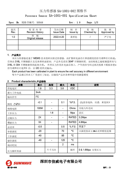
Spec.No.规格书编号:S0568Rev.:1.0Page:1/5深圳市信威电子有限公司版次Rev.变更内容Revision History发出日期Issue Date 制作Issue by 复核Checked by批准Approved by 1.0首版Original release2022-4-20黄哲伦/严子光1.产品简介本压力传感器是基于MEMS 技术的硅压阻式传感器,由扩散硅充油芯片和高精度的信号调理芯片组成。
芯体由316L 不锈钢膜片及壳体和硅油密封,产品外壳采用304F 不锈钢材质,该结构使之能够测量所有与316L 和304不锈钢兼容的流体介质。
外界压力作用在充油芯体上,产生的信号经过两次校准(模拟补偿+信号调理芯片处理)后,以I2C 的形式输出。
Each product has been calibrated in plant to ensure the well accuracy in different environment 每个产品都已经在工厂里进行了标定,以确保产品在各种环境中的测量精度Spec.No.规格书编号:S0568Rev.:1.0Page:2/5深圳市信威电子有限公司3.输出接口及管脚定义注:1.产品的内部电路已经在I2C 总线上放置了4.7K 的上拉电阻2.所有管脚与产品的金属外壳之间是绝缘的4.产品外形结构(单位:mm )5.功能描述5.1.工作模式传感器的默认工作模式为:产品上电后,进入到休眠状态,仅在接收到相应的I2C 命令后才会启动一次压力和温度的测量动作,之后再次自动进入休眠状态,以节省功耗。
5.2.上电启动及休眠唤醒当电源电压小于0.2V 时,传感器处于复位状态,在电源电压以最低10V/ms 的上升速率经过1ms 的延迟后,I2C 接口处于正常状态,可以接受主机命令,在经过2.5ms 的延迟后,传感器可以进行正常的压力和温度测量。
当传感器处于休眠状态时,在接收到主机命令后的0.5ms 时间内从休眠状态进入到工作模式,详细请参Spec.No.规格书编号:S0568Rev.:1.0Page:3/5深圳市信威电子有限公司照上电时序图6.I2C 接口6.1.I2C 接口电气特性在产品内部,I2C 总线的时钟信号线和数据线已经具有4.7k 的上拉电阻6.2.I2C 通讯速率本传感器的I2C 接口可工作于标准模式(100Kbit/s )、快速模式(400Kbit/s)、和高速模式(3.4Mbit/s)。
杜卡斯斯特拉克门系统说明书
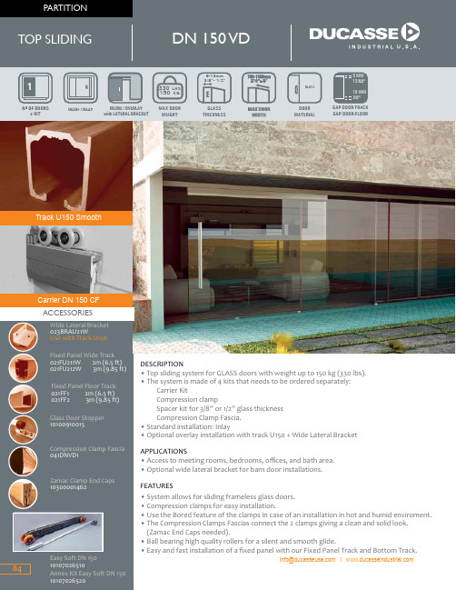
Carrier DN 150 CFTrack U150 SmoothMATERIALWEIGHT x KITTHICKNESS***********************DESCRIPTION• Top sliding system for GLASS doors with weight up to 150 kg (330 lbs).• The system is made of 4 kits that needs to be ordered separately: Carrier KitCompression clampSpacer kit for 3/8” or 1/2” glass thickness Compression Clamp Fascia. • Standard installation: Inlay• Optional overlay installation with track U150 + Wide Lateral Bracket APPLICATIONS• Access to meeting rooms, bedrooms, offices, and bath area.• Optional wide lateral bracket for barn door installations.FEATURES• System allows for sliding frameless glass doors.• Compression clamps for easy installation.• Use the Bored feature of the clamps in case of an installation in hot and humid enviroment.• The Compression Clamps Fascias connect the 2 clamps giving a clean and solid look. (Zamac End Caps needed).• Ball bearing high quality rollers for a silent and smooth glide.• Easy and fast installation of a fixed panel with our Fixed Panel Track and Bottom Track.Easy Soft DN 150DN 150 VDCARRIER TRACKALL DIMENSIONS ARE IN MM., CM., KG. USA DIMENSIONS ARE APPROXIMATE (*) Product tested using ANSI-BHMA protocol. For more information see the glossary of terms2 Carriers DN 150 VD2 Stoppers withretention deviceABDN 150 VD,set for 1 panelPART NUMBER:013221 50465 mín.9 max. 7PARTITIONCOMPRESSION CLAMP FASCIA2”1”13/16mmmm10mm3/8”5mm13/64”info@ I MASTER PACK: 4 unitsTRACK U150 SMOOTH• 10100605692• 101006056-08• 10100605693• 101006056-12• 10100605696Track U150 Smooth AL 2m (6.5 ft)Track U150 Smooth AL 8 ftTrack U150 Smooth AL 3m (9.85 ft)Track U150 Smooth AL 12 ftTrack U150 Smooth AL 6m (19.7 ft)SPACER KIT 10 8-10mm - 3/8”PART NUMBER: 013218LM2 Mounting Plates1 Floor Guide InsertSPACER KIT 1312-13mm - 1/2”PART NUMBER: 0132192 SpacersCOMPRESSION CLAMP KITPART NUMBER: 013217DE2 Compression Clamps4 ALX Caps4 Clamp End Caps4 Clamp Weatherstrips1 Segmenta Key1 Allen KeyFGHIJK1 Floor Guide VDMASTER PACK: 8 unitsTRACK U150 ALPART NUMBER DESCRIPTION• 021U1501• 021U1502• 021U1503• 021U150-08• 021U150-12Track U150 AL 2m (6.5 ft)Track U150 AL 3m (9.85 ft)Track U150 AL 6m (19.7 ft)Track U150 AL 8ftTrack U150 AL12ftMASTER PACK: 4 units OPTIONAL:TO USE WITHWIDE BRACKET85。
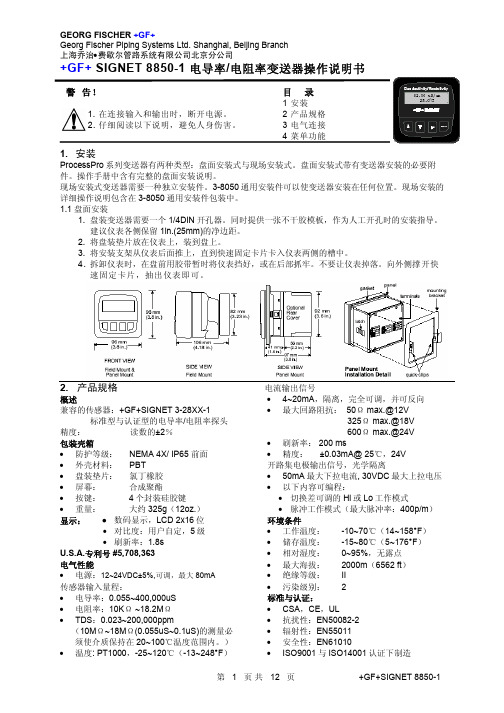
8850-1-xrh GF电导仪说明书
1.0000
> 入精确的电导常数
Cond Units:
uS
>
PPM Factor:
2.00
>
Set: Temperature >
Set: Conductivity >
Loop Source:
Cond
>
选择测量值单位:uS, mS, kΩ, MΩ, PPM
如果测量值单位设定为 PPM,要在此项中设置固体溶解总量(Total Dissolved Solids)与 uS 的比例。详见本说明书的章节 3。TDS 系数只 能按 PPM 单位设置。
3.3 开路集电极输出信号 当过程变量高于或低于设定值时,开路集电极 输出信号可以用作开关量信号,或根据过程变 量发出比例脉冲信号。
• Low 当过程变量低于设定值时,输出信号被激励。 当流量值高于设定值加切换差时,输出信号复 位。
• 比例脉冲 开路集电极将根据标定菜单(CALIBRATE)中 设定的脉冲率发出 100ms 宽的脉冲信号。
目录
1 安装 2 产品规格 3 电气连接 4 菜单功能
1. 安装
ProcessPro 系列变送器有两种类型:盘面安装式与现场安装式。盘面安装式带有变送器安装的必要附 件。操作手册中含有完整的盘面安装说明。
现场安装式变送器需要一种独立安装件。3-8050 通用安装件可以使变送器安装在任何位置。现场安装的 详细操作说明包含在 3-8050 通用安装件包装中。 1.1 盘面安装
在下面的示例中: • 当测量值小于 5.0 时,输出信号为 0p/m。 • 当测量值等于 7.5 时,输出信号为 50p/m。 • 当测量值达到 10 及以上时,输出信号为
100p/m
2SD1508中文资料
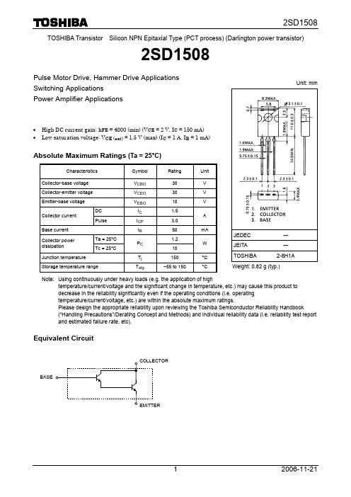
TOSHIBA Transistor Silicon NPN Epitaxial Type (PCT process) (Darlington power transistor)2SD1508Pulse Motor Drive, Hammer Drive Applications Switching ApplicationsPower Amplifier Applications• High DC current gain: h FE = 4000 (min) (V CE = 2 V, I C = 150 mA) • Low saturation voltage: V CE (sat) = 1.5 V (max) (I C = 1 A, I B = 1 mA)Absolute Maximum Ratings (Ta = 25°C)Characteristics Symbol Rating UnitCollector-base voltage V CBO 30 V Collector-emitter voltage V CEO30 V Emitter-base voltage V EBO10 V DC I C 1.5 Collector current Pulse I CP3.0ABase current I B 50 mA Ta = 25°C 1.2 Collector powerdissipationTc = 25°CP C 10WJunction temperature T j 150 °C Storage temperature rangeT stg−55 to 150°CNote: Using continuously under heavy loads (e.g. the application of hightemperature/current/voltage and the significant change in temperature, etc.) may cause this product to decrease in the reliability significantly even if the operating conditions (i.e. operating temperature/current/voltage, etc.) are within the absolute maximum ratings.Please design the appropriate reliability upon reviewing the Toshiba Semiconductor Reliability Handbook(“Handling Precautions”/Derating Concept and Methods) and individual reliability data (i.e. reliability test report and estimated failure rate, etc).Equivalent CircuitUnit: mmJEDEC ― JEITA―TOSHIBA 2-8H1A Weight: 0.82 g (typ.)BASEElectrical Characteristics (Ta = 25°C)MarkingPart No. (or abbreviation code)lead (Pb)-free package or lead (Pb)-free finish.Collector-emitter voltage V CE (V)I C – V CEC o ll e c to r c u r r e n t I C(m A )Collector-emitter voltage V CE (V)I C – V CEC ol l e ct o r c u r r e n t I C(m A )Collector-emitter voltage V CE (V)I C – V CEC o l l e c t o r c u r r e n t I C (m A )Base-emitter voltage V BE (V)I C – V BEC o l l e c t o r c u r r e n t I C (A )h FE – I CD C c u r r e n t g a i n h F ECollector current I C (A)Collector current I C (A)V CE (sat) – I CC o l l e c t o r -e m i t t e r s a t u r a t i o n v o l t a g e V C E (s a t ) (V)Collector-emitter voltage V CE (V)Safe Operating AreaCol l e c t o r c u r re n t I C (A )Collector current I C (A)B a s e -e m i t t e r s a t u r a t i o n v o l tag e V B E (s a t) (V )V BE (sat) – I CPulse width t w (s)r th – t wT r a n s i e n t t h e r m a l r e s i s t a n c e r t h (°C /W )1 3 10 30RESTRICTIONS ON PRODUCT USE20070701-EN •The information contained herein is subject to change without notice.•TOSHIBA is continually working to improve the quality and reliability of its products. Nevertheless, semiconductor devices in general can malfunction or fail due to their inherent electrical sensitivity and vulnerability to physical stress. It is the responsibility of the buyer, when utilizing TOSHIBA products, to comply with the standards of safety in making a safe design for the entire system, and to avoid situations in which a malfunction or failure of such TOSHIBA products could cause loss of human life, bodily injury or damage to property.In developing your designs, please ensure that TOSHIBA products are used within specified operating ranges as set forth in the most recent TOSHIBA products specifications. Also, please keep in mind the precautions and conditions set forth in the “Handling Guide for Semiconductor Devices,” or “TOSHIBA Semiconductor Reliability Handbook” etc.• The TOSHIBA products listed in this document are intended for usage in general electronics applications (computer, personal equipment, office equipment, measuring equipment, industrial robotics, domestic appliances, etc.).These TOSHIBA products are neither intended nor warranted for usage in equipment that requires extraordinarily high quality and/or reliability or a malfunction or failure of which may cause loss of human life or bodily injury (“Unintended Usage”). Unintended Usage include atomic energy control instruments, airplane or spaceship instruments, transportation instruments, traffic signal instruments, combustion control instruments, medical instruments, all types of safety devices, etc.. Unintended Usage of TOSHIBA products listed in his document shall be made at the customer’s own risk.•The products described in this document shall not be used or embedded to any downstream products of which manufacture, use and/or sale are prohibited under any applicable laws and regulations.• The information contained herein is presented only as a guide for the applications of our products. No responsibility is assumed by TOSHIBA for any infringements of patents or other rights of the third parties which may result from its use. No license is granted by implication or otherwise under any patents or other rights of TOSHIBA or the third parties.• Please contact your sales representative for product-by-product details in this document regarding RoHS compatibility. Please use these products in this document in compliance with all applicable laws and regulations that regulate the inclusion or use of controlled substances. Toshiba assumes no liability for damage or losses occurring as a result of noncompliance with applicable laws and regulations.。
QSS-075-01-L-D-EM2;中文规格书,Datasheet资料
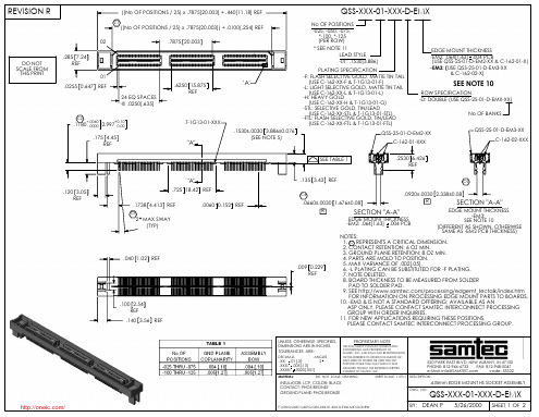
EDGE MOUNT THICKNESS -EM3: SEE NOTE 10 (DIFFERENT AS SHOWN, OTHERWISE SAME AS -EM2 PCB THICKNESS)
SECTION "A-A"
UNLESS OTHERWISE SPECIFIED, DIMENSIONS ARE IN INCHES. TOLERANCES ARE:
MATERIAL:
DO NOT SCALE DRAWING
SHEET SCALE: 1.375:1 DESCRIPTION:
INSULATOR: LCP, COLOR: BLACK CONTACT: PHOS BRONZE GROUND PLANE: PHOS BRONZE
.635mm EDGE MOUNT HS SOCKET ASSEMBLY
520 PARK EAST BLVD, NEW ALBANY, IN 47150 PHONE: 812-944-6733 FAX: 812-948-5047 e-Mail: info@ code: 55322
DESCRIPTION: DWG. NO.
DO NOT SCALE DRAWING SHEET SCALE: 2:1
DWG. NO.
QSS-XXX-01-XXX-D-EMX
5/26/2000
SHEET 1 OF 2
/
F:\DWG\MISC\MKTG\QSS-XXX-01-XXX-D-EMX-MKT.SLDDRW
BY: DEAN P
REVISION R
.0075 0.191 MAX
02 .285 7.24 REF 01 .0255 0.647 REF 24 EQ SPACES @ .0250[.635]
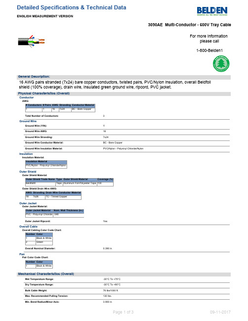
贝尔登1508B 16AWG 2对双绞线电缆 PVC绝缘,铝箔屏蔽,绿色接地线,7X24铜芯说明书
Beldfoil®
Tape Aluminum Foil-Polyester Tape 100
Outer Shield Drain Wire AWG:
AWG Stranding Drain Wire Conductor Material
18 7x26
TC - Tinned Copper
Outer Jacket Outer Jacket Material: Outer Jacket Material Nom. Wall Thickness (in.) PVC - Polyvinyl Chloride .048
Item # 3090AE 0101000 3090AE 0105000
Putup 1,000 FT 5,000 FT
Ship Weight 65.000 LB 340.000 LB
Color BLACK BLACK
Notes C CZ
Item Desc 2 #16 PVC/NYL FS + 1 #16 PVC 2 #16 PVC/NYL FS + 1 #16 PVC
General Description:
16 AWG pairs stranded (7x24) bare copper conductors, twisted pairs, PVC/Nylon insulation, overall Beldfoil shield (100% coverage), drain wire, insulated green ground wire, ripcord, PVC jacket.
NPLF, TC-ER, UL 1277
EU Directive 2011/65/EU (ROHS II):
Tropicamide_1508-75-4_DataSheet_MedChemExpress
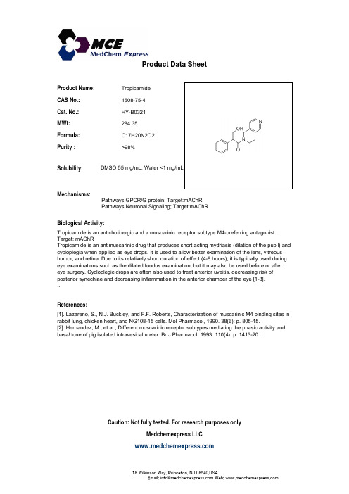
Product Name:Tropicamide CAS No.:1508-75-4Cat No :HY B0321Product Data SheetCat. No.:HY-B0321MWt:284.35Formula:C17H20N2O2Purity :>98%S l bilit DMSO 55/L W t <1/LSolubility:Mechanisms:Biological Activity:Pathways:GPCR/G protein; Target:mAChRPathways:Neuronal Signaling; Target:mAChR DMSO 55 mg/mL; Water <1 mg/mL Biological Activity: Tropicamide is an anticholinergic and a muscarinic receptor subtype M4-preferring antagonist .Target: mAChR Tropicamide is an antimuscarinic drug that produces short acting mydriasis (dilation of the pupil) and cycloplegia when applied as eye drops. It is used to allow better examination of the lens, vitreous humor, and retina. Due to its relatively short duration of effect (4-8 hours), it is typically used during eye examinations such as the dilated fundus examination, but it may also be used before or after eye surgery. Cycloplegic drops are often also used to treat anterior uveitis, decreasing risk of posterior synechiae and decreasing inflammation in the anterior chamber of the eye [13]References:[1]. Lazareno, S., N.J. Buckley, and F.F. Roberts, Characterization of muscarinic M4 binding sites inrabbit lung, chicken heart, and NG108-15 cells. Mol Pharmacol, 1990. 38(6): p. 805-15.[2]. Hernandez, M., et al., Different muscarinic receptor subtypes mediating the phasic activity and basal tone of pig isolated intravesical ureter Br J Pharmacol 1993110(4):p 141320 posterior synechiae and decreasing inflammation in the anterior chamber of the eye [1-3]....basal tone of pig isolated intravesical ureter. Br J Pharmacol, 1993. 110(4): p. 1413-20.Caution: Not fully tested. For research purposes onlyMedchemexpress LLC18W i l k i n s o n W a y , P r i n c e t o n , N J 08540,U S AE m a i l : i n f o @m e d c h e m e x p r e s s .c o m W e b : w w w .m e d c h e m e x p r e s s .c o m。
罗弗公司2010年版低功耗高电压负压电子传输器2SB1182和2SB1240产品说明书
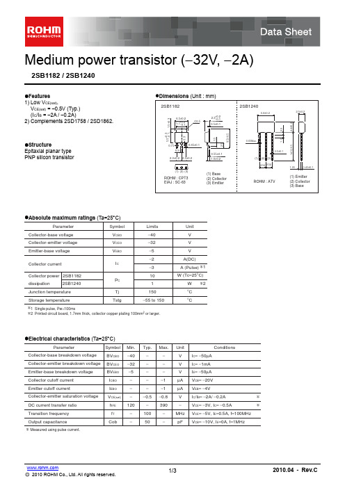
Medium power transistor (-32V, -2A)2SB1182 / 2SB1240●Features1) Low V CE(sat).V CE(sat) = -0.5V (Typ.) (I C /I B = -2A / -0.2A)2) Complements 2SD1758 / 2SD1862.●StructureEpitaxial planar type PNP silicon transistor●Absolute maximum ratings (Ta=25︒C)∗1 Single pulse, Pw =100ms∗2 Printed circuit board, 1.7mm thick, collector copper plating 100mm 2or larger.ParameterV CBO V CEO V EBO P C Tj Tstg−40V V V A(DC)W (Tc =25°C )W°C °C−32−5−2I CA (Pulse)−3101∗1∗22SB11822SB1240150−55 to 150Symbol Limits Unit Collector-base voltage Collector-emitter voltage Emitter-base voltage Collector currentCollector power dissipationJunction temperature Storage temperature●Electrical characteristics (Ta=25︒C)∗ Measured using pulse current.ParameterSymbol BV CBO BV CEO BV EBO I CBO I EBO h FE V CE(sat)f T CobMin.−40−32−5−−120−−−−−−−−10050−−−−1−1390−0.8∗∗−−V I C = −50μA I C = −1mA I E = −50μA V CB = −20V V EB = −4V I C /I B = −2A/ −0.2A V CE = −5V, I E =0.5A, f =100MHz V CB = −10V, I E =0A, f =1MHzV VμA μA −−V CE = −3V, I C = −0.5AV MHz pFTyp.Max.Unit Conditions−0.5Collector-base breakdown voltage Collector-emitter breakdown voltage Emitter-base breakdown voltage Collector cutoff current Emitter cutoff currentCollector-emitter saturation voltage DC current transfer ratio Transition frequency Output capacitance●Packaging specifications and h FEPackage CodeBasic ordering unit (pieces)TapingTL 2500h FE QR 2SB1182−TV22500−QR2SB1240Typeh FE values are classified as follows :Item h FEQ 120 to 270R 180 to 390●Electrical characteristic curvesFig.1 Grounded emitter propagationcharacteristicsBASE TO EMITTER VOLTAGE : V BE (V)C O L L E C T O R C U R R E N T : I C (m A )−−−−−−−−−−Fig.2 Grounded emitter outputcharacteristics−−−−−C O L LE C T O R C U R R E N T : I C (A )COLLECTOR TO EMITTER VOLTAGE : V CE (V)Fig.3 DC current gain vs.collector curren ( )D C C U R RE N T G A I N : hF ECOLLECTOR CURRENT : I C (mA)Fig.4 DC current gain vs.collector current ( )D C C U R RE N T G A I N : hF ECOLLECTOR CURRENT : I C (mA)Fig.5 Collector-emitter saturationvoltage vs. collector current ( )C O L L E C T O R S A T U R A T I O N V O L T A G E : V C E (s a t ) (m V )−−−−Fig.6 Collector-emitter saturationvoltage vs. collector current ( )−−−−−C O L L E C T O R S A T U R A T I O N V O L T A G E : V C E (s a t ) (m V )COLLECTOR CURRENT : I C (mA)Fig.7 Base-emitter saturation voltagevs. collector currentCOLLETOR CURRENT : I C (mA)B A S E S A T U R A T I O N V O L T A G E : V B E (s a t )(V )−−−−−Fig.8 Gain bandwidth product vs.emitter currentEMITTER CURRENT : I E (mA)T R A N S I T I O N F R E Q U E N C Y : f T (M H z )Fig.9 Collector output capacitance vs.collector-base voltageEmitter input capacitance vs. emitter-base voltageCOLLECTOR TO BASE VOLTAGE : V CB (V)EMITTER TO BASE VOLTAGE : V EB (V)C O L L E C T O R O U T P U T C A P AC I T A N C E : C o b (p F )E M I T T E R I N P U T C A P A C I T A N C E : C i b (p F )Fig.10 Safe operation area(2SB1182)−−−−−−−−−−C O L L E C T O R C U R R E N T : I C (A )COLLECTOR TO EMITTER VOLTAGE : V CE (V)NoticeN o t e sNo copying or reprod uction of this d ocument, in part or in whole, is permitted without theconsent of ROHM Co.,Ltd.The content specified herein is subject to change for improvement without notice.The content specified herein is for the purpose of introd ucing ROHM's prod ucts (hereinafter"Products"). If you wish to use any such Product, please be sure to refer to the specifications,which can be obtained from ROHM upon request.Examples of application circuits, circuit constants and any other information contained hereinillustrate the standard usage and operations of the Products. The peripheral conditions mustbe taken into account when designing circuits for mass production.Great care was taken in ensuring the accuracy of the information specified in this document.However, should you incur any d amage arising from any inaccuracy or misprint of suchinformation, ROHM shall bear no responsibility for such damage.The technical information specified herein is intended only to show the typical functions of andexamples of application circuits for the Prod ucts. ROHM d oes not grant you, explicitly orimplicitly, any license to use or exercise intellectual property or other rights held by ROHM andother parties. ROHM shall bear no responsibility whatsoever for any dispute arising from theuse of such technical information.The Products specified in this document are intended to be used with general-use electronicequipment or devices (such as audio visual equipment, office-automation equipment, commu-nication devices, electronic appliances and amusement devices).The Products specified in this document are not designed to be radiation tolerant.While ROHM always makes efforts to enhance the quality and reliability of its Prod ucts, aProduct may fail or malfunction for a variety of reasons.Please be sure to implement in your equipment using the Products safety measures to guardagainst the possibility of physical injury, fire or any other damage caused in the event of thefailure of any Product, such as derating, redundancy, fire control and fail-safe designs. ROHMshall bear no responsibility whatsoever for your use of any Product outside of the prescribedscope or not in accordance with the instruction manual.The Prod ucts are not d esigned or manufactured to be used with any equipment, d evice orsystem which requires an extremely high level of reliability the failure or malfunction of whichmay result in a direct threat to human life or create a risk of human injury (such as a medicalinstrument, transportation equipment, aerospace machinery, nuclear-reactor controller, fuel-controller or other safety device). ROHM shall bear no responsibility in any way for use of anyof the Prod ucts for the above special purposes. If a Prod uct is intend ed to be used for anysuch special purpose, please contact a ROHM sales representative before purchasing.If you intend to export or ship overseas any Product or technology specified herein that maybe controlled under the Foreign Exchange and the Foreign Trade Law, you will be required toobtain a license or permit under the Law.Thank you for your accessing to ROHM product informations.More detail product informations and catalogs are available, please contact us.ROHM Customer Support System/contact/。
SMS6P1;SMS12R-1;SMS12P-1;SMS6R1;SMS9R1;中文规格书,Datasheet资料
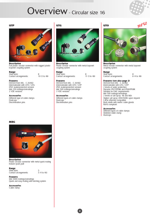
UTPDescriptionFull plastic circular connector with rugged plastic bayonet coupling system RangeShell sizes: 8Contact arrangements: 10 (3 to 48)FeaturesDerived from MIL - C 26482Intermateable with UTO / UTG IP65 (waterprotected version)Min 250 matings/unmatings 2 VDE versionsAccessoriesDifferent type of cable clamps DustcapsDiscrimination pinsUTGDescriptionPlastic circular connector with metal bayonet coupling system RangeShell sizes: 8Contact arrangements: 11 (3 to 48)FeaturesDerived from MIL - C 26482Intermateable with UTO / UTP IP65 (waterprotected version)Min 500 matings/unmatings 3 VDE versionsAccessoriesDifferent types of cable clamps DustcapsDiscrimination pinsUTODescriptionMetal circular connector with metal bayonet coupling system RangeShell sizes: 8Contact arrangements:8 (4 to 48)Features (see also page 2)Derived from MIL - C 26482Intermateable with UTG / UTP 2 levels of water protection:Dynamic IP67/IP69K and IP68/IP69K Suitable for EMC requirements Min 500 matings/unmatings2 levels of salt spray: 48 and 96hHigher salt spray (200/500h) upon request Cat5e ethernet compatibleBack shells with metric cable glands RoHS compliantAccessoriesDifferent types of cable clamps Shielded cable clamp DustcapsMBGDescriptionPlastic circular connector with metal quick mating feature (push-pull)RangeShell sizes: 5Contact arrangements:5 (4 to 46)FeaturesMin 5000 matings/unmatingsQuick and easy mating with latching system Accessories Cable clampn e wMS-M MSOV35 - DTE/DCEDescriptionHigh performance rectangular cable connector RangeShell sizes: 9Contact arrangements: 9 to 75FeaturesPer MIL - C 28748 Intermateable with MSO AccessoriesDifferent types of cable clamps Guide and jackscrew pins Pin protection shrouds Discrimination pinsDescriptionRectangular boardmount connector to mate with MS-M cable connectors RangeShell sizes:5Contact arrangements: 5 straight (9 to 75)3 right angle (9,18,34)FeaturesSolid machined or stamped and formed contacts Intermateable with MS-M AccessoriesGuide and jackscrew pinsDiscrimination pinsDescriptionRectangular cable and boardmount connector for V .35 DTE/DCE interface applicationsRange1 shell size with 34 contact positionsstraight and right angle boardmount connector FeaturesIn compliance with international standards of ISO 2593 for TSS V .35 interfacingSolid machined or stamped and formed contacts for boardmount connectorShielded cable and boardmount connectors availableAccessoriesDifferent type of cable clamps (incl. shielded) Guide and jackscrew pinsPin protection shrouds and discrimination pinsSMS - Qikmate cable connectors SMS - Qikmate boardmountDescriptionLow cost rectangular cable connectors for cable to cable and cable to panel applications RangeShell sizes: 10Contact arrangements:10 (2 to 36)FeaturesIntermateable with SMS Boardmount Moulded-on cable hood No extra hardware requiredPositive locking with retaining latchesDisrrimination cavities in between contact cavities AccessoriesPin protection shrouds Discrimination pins Tie wrapsDescriptionLow cost rectangular boardmount connector to mate with SMS cable connectors RangeShell sizes:10Contact arrangements: 10 straight (2 to 36)4 right angle (3,6,12,18)FeaturesSolid machined or stamped and formed contacts No extra hardware requiredIntermateable with SMS cable connectorsDisrrimination cavities in between contact cavities AccessoriesDiscrimination pinsMSG / MBDescriptionCable (MSG + MB) and boardmount (MSG) connectors with lever locking system.RangeShell sizes: 1 for MSG 1 for MB Contact arrangements: 50 + 59 for MSG 52 for MB FeaturesLever locking system – easy mating MSG is 19” rack mountable Polarization features available Anti jack knife system on MBn e wRM/RC-M (size 16)DescriptionMachined Snap in pin and socket contacts for heavy duty top performance requirements. Range30 to 14 AWG – 0.05 to 2.5 mm2Crimp, PC Boardmount, HandsolderWire wrap, Grounding contactsFeaturesCurrent rating: 13 AmpsPlating: Gold or TinColour coded for different wire sizesSM/SC-M (size 16)DescriptionTwo piece strip formed snap in pin and socketcontacts.Range26 to 14 AWG – 0.13 to 2.0 mm2Crimp.FeaturesCurrent rating: 13 AmpsPlating: Gold or TinRMDX/RCDX (size 16)DescriptionSnap in pin and socket coaxial contacts for a widerange of coaxial and twisted pair cables.RangeMulti piece or Monocrimp design.Typical coaxial cables are: RG161, RG178, RG179.RG188.FeaturesPlating: GoldFibre optic (size 16)DescriptionSnap in pin and socket fibre optic contacts for theintegration of optical links.RangePlastic optical Fibre (POF):1mm core and 2.2mm jacket.Plastic clad Fibre (PCF):230 µm core and 2.2 mm jacketMultimode Silica Fibre:50/125 µm type 1.5mm (or 900 µm) jacket.FeaturesSocket contact is spring loaded to avoid any airgap between the optical faces.RM/RC-W (size 20)DescriptionMachined Snap in pin and socket contacts for heavy duty top performance requirements. Range26 to 18 AWG – 0.13 to 1.0 mm2Crimp and PC BoardmountFeaturesCurrent rating: 7.5 AmpsPlating: Gold SM/SC-W (size 20)DescriptionTwo piece strip formed snap in pin and socket contacts.Range26 to 20 AWG – 0.13 to 0.5 mm2Crimp.FeaturesCurrent rating: 5 AmpsPlating: GoldUTOWDescriptionMetal circular connector with metal bayonet coupling system.RangeShell sizes: 8Contact arrangements: 8 (6 to 61) Features (see also page 2)2 levels of water protection:Dynamic IP67/IP69K and IP68/IP69KSuitable for EMC requirementsMin 500 matings/unmatings2 levels of salt spray: 48 and 96hHigher salt spray (200/500h) upon request Back shells with metric cable glandsRoHS compliantAccessoriesDifferent types of cable clampsShielded cable clampDustcapsDiscrimination pinsn e wUTV seriesDescriptionRuggedized metal circular connector for heavy duty applicationsRangeShell sizes: 8Contacts arrangements: 9 (7 to 60)FeaturesCompletely intermountable with VG95237: the MS5015 reverse bayonet connectors.2 levels of waterprotection:Dynamic IP67/69K and IP68/69K Up to 500 h salt spray.AccessoriesStraight back shells Right angle back shells Grommets and filler plugsCircular & Rectangular power versionsDescriptionPower connectors are connectors to meet mixed power / signal requirements.This range of power connectors is an extension of the long established and popular TRIM TRIO connector series8291 (power)DescriptionMachined snap in pin and sockets contacts for power applicationsRange Size 12 contacts: 20 to 14 AWG – 0.5 to 2.5 mm 2Size 8 contacts:16 to 8 AWG – 1.5 to 10 mm 2FeaturesCurrent rating: 26 Amps for size 12 contacts44 Amps for size 8 contactsPlating: Gold or Silver for size 12 contactsGold for size 8 contactsn e w分销商库存信息:SOURIAU-CONNECTIONSMS6P1SMS12R-1SMS12P-1 SMS6R1SMS9R1SMS2R1SMS2P1SMS9P1SMS24R-1 SMS36R-1SMS9PDH1SMS3PDH1 SMS12PDH1SMS36PDH1SMS12RDH1 SMS3P1SMS3R1SMS4R1SMS24P-1SMS18P1SMS36P-1 SMS2PDH1SMS4PDH1SMS6PDH1 SMS24PDH1SMS9RDH1SMS15PDH1 SMS6RDH1SMS24RDH1SMS18R1 SMS4P1SMS15R1SMS15P1 SMS18PDH1SMS2RDH1SMS3RDH1 SMS4RDH1SMS18RDH1SMS15RDH1 SMS36RDH1UTG12AC UTG14AC UTG18-AC UTG20AC UTG10PG UTG18PG UTG24PG UTG10AC UTG16AC UTG12PG UTG14PG UTG20PG UT014JCS UT018ACUT024AC UT016JC UT018JCL UTG22AC UTG16PG UTG22PGUT010JCS UT010AC UT012ACUT014AC UT012JCS SM20M-1TK6 SM14M1TK6SM24M1TK6SM16M1TK6 SM20W-3S26SM24W-3S26SC16M1TK6 SC24M1TK6SC14M1TK6SC20W-3S25 SC24W-3S25SM16ML-1TK6SM20M-1S6 SM24M-1S6SM14M-1S6SM16M-1S6 SC16ML-1TK6SC20ML-1TK6SC16M-1S6 SC14M-1S6SC24M-1S6SC20M-1S6 SC24WL-3S25SM24WL-3S26SM24WL-3TK6 SM20WL-3TK6SC24WL-3TK6SC20WL-3TK6 SM14ML-1S6SM16ML-1S6SC14ML-1S6 SC16ML-1S6SC20ML-1S6RC20M12D28 RM16M23D28RM20M12D2882911684ZX RM12Z43D2882911685NZX RC12Z43D28 SC20M-1TK6SM14ML-1TK6SM24ML-1TK6 SC24ML-1TK6SC14ML-1TK6SM20WL-3S26 SC20WL-3S25SM24ML-1S6SM20ML-1S6 SC24ML-1S6RC16M23D28SM20ML-1TK6 UTP01412S UTP0104S UTP0104P UTP0128S UTP0128P UTG01619S UTP01619P UTG014-12S UTG612-8PN UTP02448S UTG614-12PN UT001412SH。
WISE-EdgeLink DataSheet说明书

WISE-EdgeLink DataSheet 1Date Revision Description Creator Jan. 26,2022v1.0Release version Lili.Zheng2CONTENTS1SOFTWARE OVERVIEW (4)1.1What is EdgeLink? (4)1.2System Architecture (4)1.3Features of EdgeLink (5)1.4Function List (5)1.5Southbound Driver List (9)1.6Northbound Service List (13)2HARDWARE PLATFORMS (15)2.1Hardware with Built-in EdgeLink (15)31Software Overview1.1 What is EdgeLink?In application scenarios, a gateway connects to various smart devices via the southbound interface and connects with different platforms via the northbound interface. In IoT-based businesses, a gateway acts as the IoT big data core hub, which manages data collection, processing, and forwarding, and is located in the middle layer between devices and platforms.EdgeLink is a software system applied to Advantech gateway. It consists of EdgeLink Studio and EdgeLink Runtime.EdgeLink Studio: a gateway configuration tool for off-line communication and network interface configuration. It supports one-click downloads to the gateways and supports online device status management and monitoring.EdgeLink Runtime: EdgeLink services running on the gateway. It implements configurations set by EdgeLink Studio.1.2 System Architecture41.3 Features of EdgeLink•Configure a gateway with Windows utility•Support the collection and forwarding of multiple southbound and northbound communication protocols, such as MQTT, AMQP, LwM2M, OPC UA, Modbus, IEC-104, DNP3.0, etc.•‘One-click’ downloads for data communication and network configurations•Unified device networking management•Real-time gateway status monitoring1.4 Function ListFunction List Function Classification Function DescriptionProject Management Project Setup Setup a new project:Create a project file via EdgeLink Studio.Upload current projects of the gateway by using on-line devices. Implementationmethods:Single gatewaydownloadBatch gatewaydownloadOn-line implementationThere are 3 ways to recognize the node:Node ID (Gateway hardware DIP switch for identifying the gateway)IP/domain name (Gateway network information which can be obtained by searching)Azure connection string (Connection string provided by Microsoft Azure)Off-line implementation:Export the project to SD card, and manually import it to the device. Gateway replication Make a copy of gateway configuration in the project.Show project tag count Show the total number of tags in the project. (System tags are not included.) Add and delete device Devices connected to the gateway can be managed flexibly.Excel import and export(all tags)Export tags to Excel for further editing and import tags into the project.Data Collection Collect data from southbound interfacePorts:EthernetSeral portCANUSB5Devices:Southbound protocolParameter configurationAdd tagTag propertyDevice templateSystem tag Basic information and hardware status of the gateway.User tag Virtual IO tag which can be selected and configured by the user. Calculated tag Calculated results of an expression.Data Processing Data storage Store data to the expansion card. Store data of Container to the /data path.Resume broken transfer:When network interrupt/recovery occurs during data forwarding, the datagenerated during the interrupt can be retransferred.Logic operation Support complex logical operations.Event trigger (alarm) Alarm modes:Sending SMSSending e-mailWriting tagData transmission Different devices in the field can assign each other.Data Forwarding Industry protocol Electric power: DNP3Electric power: IEC104BA:BACnetCommon industrial protocol:ModbusAdvantech Proprietary protocol:WASCADAOPC-UA6Cloud connection MQTT:AWSAzureCumulocityIotDeviceOn/BIGoogle Cloud IoT CoreIotConnectiSysCore OSMindSphereSimpleMQTTSparkplug(B)T-SystemWebAccessWISE-Paas/DataHubAli CloudBaidu TiangongLanzhuo supOSProudsmartLightweight M2M LwM2MExcel import /export(northbound protocoland cloud connectiontags)Database transmitting SQL ServerMySQLORACLEFTP ServerRemote management VPN Open VPNWebAccess/VPNEdgeLink/VPNOn-line monitoring Tag read/writeI/O status:I/O status monitoring of the gatewaySystem information:Cellular statusSystem logStorage data querySystem configuration:System upgradeTime settingConnection System connection VPN:7mechanism OpenVPN (user-built)Dandelion VPN (user-built)Advantech VPNWebAccess/VPN (user-built)EdgeLink/VPN (Provide free trial within 10 gateways for domestic users)L2TP/IPsecPPPOETCP connection Active connection:Connect WebAccess/SCADAConnect Four-FaithOther customized connectionsSerial port bridgingSystem Configuration Network configuration Basic configuration:DHCPFixed IPWIFI/4GReconnect:Network status monitoring and real-time repairRouting configurationPriority configurationPort forwardingNATDHCP ServerLED configuration RUNProgramErrorTime configuration DateTimeTime zoneService configuration SSHHTTPSTelnetFTP ServerFirewall configurationSecurity Mechanism Project download Set passwordFile transfer encryption TLS1.2 On-line monitoring Login with password Security strategy Regular vulnerability scanVulnerability repair81.5 Southbound Driver List►Standard ProtocolDevice Type Models/Protocol EdgeLink Driver InterfacePower Industry Protocol DNP 3.0 DNP 3.0 (Only ADAM-3600/ECU-1051/ECU-1251/ECU-4553supported)SERIAL & TCP/IPIEC 60870-5-101 IEC 60870-5-101 SERIALIEC 60870-5-103 IEC 60870-5-103 SERIALIEC 60870-5-104 IEC 60870-5-104 TCP/IPPower Meter DL/T 645-2007 DL/T 645-2007 SERIAL DL/T 645-1997 DL/T 645-1997 SERIALIEC 62056-21 IEC 62056-21 SERIALWISE-M500 series (Advantech) Modbus/RTU SERIAL Database MS SQL Server ODBC for Microsoft SQL Server TCP/IPORACLE JDBC for ORACLE Database TCP/IP OPC UA OPCUA Client OPC UA TCP/IPBACnet Standard protocol for buildingcontrollers BACnet IP TCP/IP BACnet MS/TP SERIALSNMP Simple Network ManagementProtocolSNMP TCP/IPModbus Modbus GW Modbus TCP with limitedconnectionsTCP/IP ►PLC DriverManufacturer Models EdgeLink Driver TypeABB Controller models: AC31, AC80,AC410, AC450. Modbus via MVImodule.Modicon (Modbus RTU) SERIAL4600 Dissolved Oxygen Analyzer Modicon (Modbus RTU) SERIALCommander 1900 ControllerRecorders.Modicon (Modbus RTU) SERIALINSUM Modbus-LON NetworkGatewayModicon (Modbus RTU) SERIALMODCELL, MOD 30ML andCommander 100, 150, 200, and 300Modicon (Modbus RTU) SERIALLoop Controllers.Advantech ADAM-2000 series Advantech ADAM 2000 Series(ADAM ASCII/Modbus RTU)SERIALADAM-4000 series Advantech ADAM 4000 Series(ADAM ASCII/Modbus RTU)SERIALADAM-5000 series Ethernet Advantech ADAM-5000 Ethernet(Modbus/TCP)TCP/IPAPAX series Controller Advantech APAX Series PLC(CODESYS API)SERIAL & TCP/IP WebCon 2000 Series Advantech WebCon 2000 Series SERIAL & TCP/IPWebOP HMI Advantech WebOP HMI (ModbusRTU/TCP)SERIAL & TCP/IPAllen-Bradley PLC-5 Series Models: PLC-5/11, 5/20,5/30, 5/40, 5/40L, 5/60, 5/60L, SerialDF1 full duplex Allen-Bradley PLC-5 Series (DF1 Protocol over Serial)SERIALSLC-500 Series Models: SLC 5/03, 5/04, 5/05, Serial DF1 full duplex Allen-Bradley SLC-500 Series (DF1 Protocol over Serial)SERIALMicro Logix Series PLC Allen-Bradley Micro Logix SeriesPLC (DF1 Protocol over Ethernet)TCP/IPAllen Bradley CSP to Modbus Ethernet Modicon (Modbus RTU/TCP) SERIAL & TCP/IPControlLogix series, CompactLogix series PLC Allen-BradleyControlLogix&CompactLogix SeriesPLC (Ethernet/IP)TCP/IPBECKHOFF BECKHOFF TwinCAT PLC BECKHOFF TwinCAT PLC(BECKHOFF ADS API)TCP/IPDELTA DVP series PLC Delta DVP Series PLC (ModbusRTU/TCP)SERIAL & TCP/IP FATEK FACON FB series PLC Fatek and Facon PLCs SERIAL & TCP/IPGE GE Fanuc Series 90-30 via SNP, SerialSNP GE Fanuc Series 90-30 via SNP,Serial SNP (SNP and SNP-X serial)SERIAL & TCP/IPGE Fanuc Series 90-70 via SNP, Serial SNP GE Fanuc Series 90-70 via SNP,Serial SNP (SNP and SNP-X serial)SERIAL & TCP/IPFieldServer Modbus Modicon (Modbus RTU/TCP) SERIAL & TCP/IPGE Multilin Power ManagementModules via ModbusModicon (Modbus RTU) SERIAL1011 FieldServer Modbus Ethernet Modicon (Modbus RTU/TCP) SERIAL & TCP/IPHoneywell 7800 series Burner Controls withS7810M ModBus Networking moduleModicon (Modbus RTU) SERIALDCP100 with Modbus communications Modicon (Modbus RTU) SERIALDPR100 DPR180/250 Recorders withModbusModicon (Modbus RTU) SERIAL DR 4300/4500 Recorders with Modbus Modicon (Modbus RTU) SERIALUDC700 UDC1000 UDC1500 LoopController with ModbusModicon (Modbus RTU) SERIALUDC 3000, UDC 3300 Loop Controllerswith ModbusModicon (Modbus RTU) SERIALUDC 6000 Loop Controller withModbusModicon (Modbus RTU) SERIALUMC800 Setpoint Programmer /Controller with ModbusModicon (Modbus RTU) SERIAL VPR/VRX Recorders with Modbus Modicon (Modbus RTU) SERIALHoneywell HC900 Hybrid ControlSystemModicon (Modbus/TCP) TCP/IPKeyence KEYENCE KV-700/ KV-1000 seriesPLCs KEYENCE KV-700/ KV-1000 (HostLink)SERIAL & TCP/IPMitsubishi Melsec A Mitsubishi MELSEC-A SeriesPLC(MC Protocol)SERIAL & TCP/IPMelsec A1S Mitsubishi MELSEC-AnS SeriesPLC(MC Protocol)SERIAL & TCP/IPMitsuA2 Mitsubishi MELSEC-AnN SeriesPLC(MC Protocol)SERIALMitsuAnA Mitsubishi MELSEC-AnA SeriesPLC(MC Protocol)SERIAL & TCP/IPMitsuAnAD Mitsubishi MELSEC-AnAD SeriesPLC(MC Protocol)SERIALMelsec FX Series PLC Mitsubishi MELSEC-Fx Series PLC(MC Protocol)SERIAL & TCP/IPMelsec FX - Series MultiDrop IO Mitsubishi MELSEC-Fx Series PLC(MC Protocol)SERIALMelsec FX2 Series PLC Mitsubishi MELSEC-Fx2 Series PLC(MC Protocol)SERIAL & TCP/IPMelsec FX3 Series PLC Mitsubishi MELSEC-Fx3 Series PLC(MC Protocol)SERIAL & TCP/IPMelsec FX5 Series PLC Mitsubishi MELSEC-Fx5 Series PLC(MC Protocol)SERIAL & TCP/IP12 Melsec Q Mitsubishi MELSEC-Q Series PLCwith Extension Module(MCProtocol)SERIAL & TCP/IPMelsec QCPU Mitsubishi MELSEC-Q SeriesPLC(MC Protocol)SERIALOmron Omron C Series PLCs Omron C Series PLC (HostLink) SERIAL & TCP/IP Omron CJ Series PLCs Omron CJ Series PLC (HostLink) SERIAL & TCP/IPOmron CP Series PLCs Omron CP Series PLC (HostLink) SERIAL & TCP/IPOmron CS Series PLCs Omron CS Series PLC (HostLink) SERIAL & TCP/IPOmron CV Series PLCs Omron CV Series PLC (HostLink) SERIAL & TCP/IPOmron E5 Series PLCs Omron E5 Series PLC (HostLink) SERIALOmron NX/NJ Series PLCs Omron NX/NJ Series PLC(EtherNet/IP)TCP/IPPanasonic FP3 Serial via Modbus MB Link moduleAFP3492Modicon (Modbus RTU) SERIALFPSH10 Serial via Modbus MB Linkmodule AFP3492Modicon (Modbus RTU) SERIALFP0,FP-X, FP2 series PLC via Mewtocol Panasonic FP0, FP-X, FP2 SeriesPLC (Mewtocol)SERIAL & TCP/IPSchneider TSX Premium and TSX Micro Series viaModbusModicon (Modbus RTU) SERIALModcion 484, 584, 884 PLCs Modicon (Modbus RTU) SERIALModicon 984 PLCs Modicon (Modbus RTU) SERIALQuantum PLCs Modicon (Modbus RTU) SERIALAEG Compact PLC Modicon (Modbus RTU) SERIALION6200 Schneider ION6200 (Modbus RTU) SERIALModicon Momentum M1E PLCs Modicon (Modbus TCP) TCP/IPModicon Quantum PLCs Modicon (Modbus TCP) TCP/IPSharp Sharp JW series PLC Sharp JW series PLC SERIAL Siemens Siemens Cerberus MXL Modicon (Modbus RTU/TCP) SERIAL & TCP/IP Siemens S7-200 PLC Siemens S7-200 PLC (PPI) SerialSiemens S7-200 PLC via Modbus Modbus RTU (Modicon) RS-232, RS-485Siemens S7-300 Siemens S7-300/1200/1500 PLC(S7Comm TCP/IP)SERIAL & TCP/IPSiemens S7-1200 Siemens S7-300/1200/1500 PLCSERIAL & TCP/IP(S8Comm TCP/IP)SERIAL & TCP/IP Siemens S7-1500 Siemens S7-300/1200/1500 PLC(S9Comm TCP/IP)Siemens LOGO! PLC via Ethernet Siemens LOGO! PLC via Ethernet TCP/IPSERIAL & TCP/IP Toyopuc Toyopuc PLCs Toyopuc 2PORT-EFR PLC viaEthernetWago 750 WAGO I/O System 750 FieldbusWAGO I/O System 750 SERIALCoupler for Modbus Serial. Models750-312, 750-314, 750-315,750-316, 750-812, 750-814,750-815WAGO I/O System 750 FieldbusWAGO I/O System 750 TCP/IPCoupler for Modbus. Models 750-342TCP/IP Yaskawa YASKAWA MP series YASKAWA MP Series Ethernet(Extension)SERIAL & TCP/IP MP900 series YASKAWA MP900 series, MemoBusModbus compatible (ModbusRTU/TCP)MP3000 series YASKAWA MP3000 series TCP/IPSERIAL & TCP/IP Yokogawa FA-M3 RS-232 Factory ACE PLCs Yokogawa FA-M3 Ethernet FactiryACE PLC1.6 Northbound Service ListService Classification Service ListNorthbound protocol and platform ActiveConnection (WASCADA)MQTTModbus RTUModbus/TCPBACnetOPC UAIEC-104DNP3 (Only for ADAM-3600 and ECU Series) Northbound database SQL ServerMySQLORACLEFTP Server13Cloud Platform AliyunAWSBaidu TiangongCumulocityIotCustomMQTTDeviceOn/BIGoogle Cloud IoT CoreIoTConnectiSysCore OSMindSphereLanzhuo supOSProudsmartSimpleMQTTSparkplug(B)T-SystemWebAccessWISE-PaaS/DataHubAzureLwM2M142Hardware Platforms2.1 Hardware with Built-in EdgeLink 15。
崇瀚科技 CH-R4 无线路由器用户手册说明书
2016-5-11崇瀚科技ChonghanPower by Chonghan页1重要提示由于无线通信的性质,传输和接收的数据永远不能得到保证。
数据可能会延迟,损坏(即有错误),或完全丢失。
虽然在一个结构良好的网络下正常的使用崇瀚科技无线设备,重大延迟或丢失数据的情况很少,崇瀚科技无线设备不应使用在以下情形:发送或接收数据失败可能导致用户或任何其他当事方任何形式的损害,包括但不限于人身伤害,死亡或财产损失。
崇瀚科技不承担任何由于数据收发延迟,错误,或数据收发失败造成的损害赔偿责任。
安全及危害不要在以下区域使用崇瀚科技无线设备:爆破操作区域,将要爆破的区域,医疗设备附近,生命支持设备附近,或任何可能受到任何形式的无线电干扰的设备附近。
在这些区域崇瀚科技无线设备必须关闭。
崇瀚科技无线设备传输的信号可能干扰这些设备。
不要在任何飞机上使用崇瀚科技无线设备,不论飞机在地面或飞行。
在飞机上崇瀚科技无线设备必须关闭。
当崇瀚科技无线设备运行时,传输的信号可能会干扰各种机载系统。
注意:一些航空公司可能会允许当飞机在地面而且飞机门是敞开的时候使用移动电话。
崇瀚科技无线设备在此时可以使用。
交通工具驾驶人员不能在驾驶交通工具时使用崇瀚科技无线设备。
否则将有影响驾驶人员对车辆的操作。
在一些国家和省,驾驶过程当中操作无线设备,属违法行为。
责任限制本手册的内容按原样提供。
崇瀚科技不承担任何类型的担保,明示或暗示保证,包括任何暗示的适销性担保,特定用途,或者非侵权。
本手册中的信息如有变更,恕不另行通知。
崇瀚科技及其关联公司特别声明不承担由于使用崇瀚科技产品而产生的任何及所有直接,间接的,特殊的,一般的,偶然,必然,惩戒性损害赔偿,包括但不限于损失或收入或所得的收入预期或输出利润。
版权信息©2010-2017深圳市崇瀚科技开发有限公司版权所有注册商标“崇瀚科技®”是深圳市崇瀚科技开发有限公司的注册商标。
W INDOWS®是微软公司的注册商标。
iManager NetEco软件数据表(网站)说明书
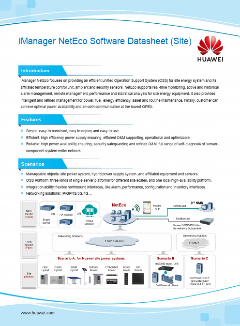
iManager NetEco Software Datasheet (Site)IntroductioniManager NetEco focuses on providing an efficient unified Operation Support System (OSS) for site energy system and its affiliated temperature control unit, ambient and security sensors. NetEco supports real-time monitoring, active and historical alarm management, remote management, performance and statistical analysis for site energy equipment. It also provides intelligent and refined management for power, fuel, energy efficiency, asset and routine maintenance. Finally, customer can achieve optimal power availability and smooth communication at the lowest OPEX.Features●Simple: easy to construct, easy to deploy and easy to use.●Efficient: high efficiency power supply ensuring, efficient O&M supporting, operational and optimizable.●Reliable: high power availability ensuring, security safeguarding and refined O&M, full range of self-diagnosis of 'sensor-component-system-entire network'.Scenarios●Manageable objects: site power system, hybrid power supply system, and affiliated equipment and sensors.●OSS Platform: three kinds of single server platforms for different site scales, and one local high-availability platform.●Integration ability: flexible northbound interfaces, like alarm, performance, configuration and inventory interfaces.●Networking solutions: IP/GPRS/3G/4G…SpecificationsItemsSpecifications and FeaturesDeployment Solutions and System CapacityDeployed on HUAWEI serversDeployed on customer’s specific Virtual Machine (based on Vmware vSphere 5.5 or later version) (*O)Single /S Single /M Single /L Local HA (*O)Single /S Single /M Single /L 2,000 sites4,000 sites10,000 sites10,000 sites2,000 sites4,000 sites10,000 sitesNetworking IP, GPRS, 3G, 4G, etc.Basic Platform FunctionsBasic NetEco service and online help; clock synchronization and time zone management; disk redundancy backup; NetEco data backup and restore; NetEco system self-diagnosis; customized homepages; one-touch search.Alarm Mgmt.Alarm collection and storage; alarm browse; alarm processing; alarm setting; customized dry contact alarm management; alarm masking andalarm thresholds setting; root cause analysis of shutdown site, risky site forecast; alarm troubleshooting expert advice and closed-loopmaintenance experience base.Real-time Monitoring GIS site navigation; network-level real-time monitoring; site information overview; graphical user interface and energy flow; energy network KPI-guarding.Configuration Management Site controller discovery, graphical drag and drop site configuration, batch sites copy and batch parameters modification, site parameter setting by SMS, configuration data export to EXCEL.Performance and Report Historical data collection, query, statistical analysis; Day/Week/Month/Year report management; customized report; automatic periodic report; energy network KPI report. Report export: CSV, PDF, EXCEL files, printer or email.Software Management Site system and components versions browse; site software package management; site software upgrade task management; remote and batch upgrade supported.System and User Security System security management; user role and authority management; access security management (security policy, online users view, AccessControl List (ACL) management); Mobile App access management; site user management.Log Mgmt.Element Management System (EMS) log; element operation log; element fault log.Efficient and Accurate O&M (*O)Alarm remote notification; Mobile APP management; overall network battery management (one user interface for battery related alarm, status; remote batch or scheduled battery test and test report); overall network diesel generators and fuel management (one user interface for DG related alarm, status; refueling business audit and anti-theft); multi-tenant shared site management; intelligent Mix of energy storage system management.EnergyEfficiency (*O)Site and overall network energy efficiency management, abnormal energy efficiency pre-warning and optimization expert advice; staggering electricity usage; diesel Max II management; optimal utilization of solar power in Solar-DG system management.Health and Lifespan Mgmt.(*O)State of Health (SOH) management, visible battery status (healthy, sub-healthy, abnormal), cycle times, prediction of battery remaining capacity (SOC); SOH management of diesel generator, DG maintenance reminder; abnormal SOH pre-warning and optimization expert advice.Assets Mgmt.(*O)Inventory management for Huawei energy equipment and NetEco server platform, asset anti-theft; inventory data export to EXCEL and XML files.Site Security Mgmt. (*O)Camera with smart capture or web access; video surveillance subsystem integration with Huawei eSpace VCN3000; access control management; intelligent lock of energy storage system management.Integration with 3rd Party (*O)Northbound interfaces: Alarm SNMP (SNMPv1, SNMPv2c, and SNMPv3), Performance SNMP (SNMPv3), Webservice (https +Restful +JSON) for alarm, performance, configuration and inventory data; FTP/FTPS of performance, configuration and inventory data.Remarks: Features are constrained to the configuration of site hardware and controller software, as well as NetEco versions. (*O): means optional.HUAWEI TECHNOLOGIES CO.,LTD.Huawei Industrial BaseBantian LonggangShenzhen 518129,P.R.ChinaTel:+86-755-28780808Copyright © Huawei Technologies Co., Ltd. 2019. All rights reserved.No part of this document may be reproduced or transmitted in any form or by any means without prior written consent of Huawei Technologies Co., Ltd.General DisclaimerThe information in this document may contain predictive statements including, without limitation, statements regarding the future financial and operating results, future product portfolio, new technology, etc. There are a number of factors that could cause actual results and developments to differ materially from those expressed or implied in the predictive statements. Therefore, such information is provided for reference purpose only and constitutes neither an offer nor an acceptance. Huawei may change the information at any time without notice.。
马达驱动电路MX1508RX2产品手册_V1.1
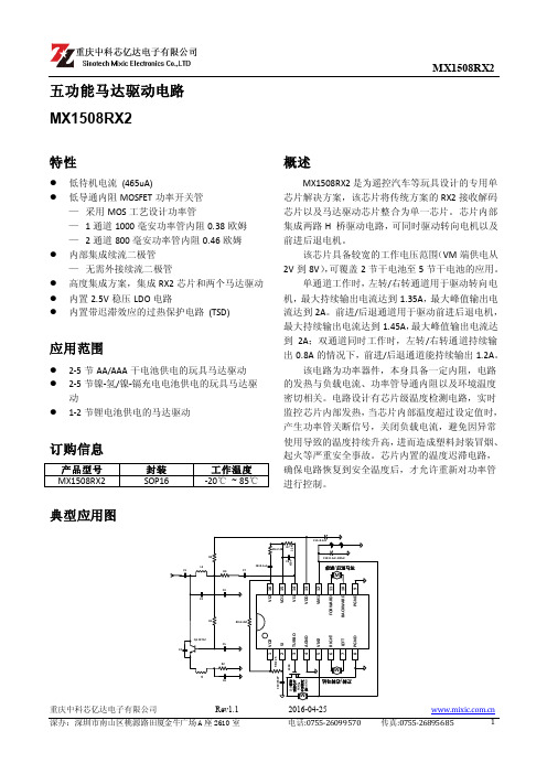
传真:0755-26895685
4
SinotechMixic Electronics Co.,LTD
MX1508RX2
电特性参数表
(TA=25℃, VM =6.5V 除非另有规定)
参数
符号 条件
电源参数
VM 待机电流
IVMST
功 率 管 导通内阻
1 通道导通内阻
IO=±200mA VM1=6.5V TA=25℃ RON1 IO=±1000mA VM1=6.5V TA=25℃
该电路为功率器件,本身具备一定内阻,电路 的发热与负载电流、功率管导通内阻以及环境温度 密切相关。电路设计有芯片级温度检测电路,实时 监控芯片内部发热,当芯片内部温度超过设定值时, 产生功率管关断信号,关闭负载电流,避免因异常 使用导致的温度持续升高,进而造成塑料封装冒烟、 起火等严重安全事故。芯片内置的温度迟滞电路, 确保电路恢复到安全温度后,才允许重新对功率管 进行控制。
℃
TJ
150
℃
Tstg
-55~+150
℃
焊接温度
TLED
260℃,10 秒
注:(1)、VM 代表 VM1 和 VM2,1 通道代表 FORWARD 和 BACKWARD 通道,2 通道代表 RIGHT 和 LEFT 通道。
(2)、不同环境温度下的最大功耗计算公式为: PD=(150℃-TA)/θJA
解码频率
内置振荡频率
FOSC
允许发射频率的偏差
电特性曲线图
最小值 典型值 最大值 单位
465
uA
0.35 0.38
Ω 0.43 0.46
2.593 2.594
V 2.584 2.595
128
sonardyne 罗德斯塔-陀螺配件 6 数据表说明书

DatasheetLodestar - GyroCompatt 6DescriptionLodestar GyroCompatt 6 integrates Sonardyne’s Wideband® 2 acoustic positioning and Lodestar AHRS technology in one small, highly versatile and robust instrument. This provides high update rate wireless attitude, heading, heave, surge,sway, temperature, pressure, SV and acoustic positioning of any subsea object.Compatible with USBL and LBL positioning systems, the LodestarGyroCompatt 6 provides real time motion data for structure deploymentvia the integrated high speed acoustic modem.The internal high capacityrechargeable battery pack enables quick charge times and up to 28 hours of continuous operation with the ability to turn the gyro on and off to save battery life giving over two months of transponder life. The instrument is small and light enough to be ROV installed and a mechanical stab enables precision alignment to any structure. ApplicationsStructure position and orientation can be accurately determined during lowering, set-down and as-built surveys. Using the Lodestar GyroCompatt 6 for metrologydelivers the measurements required for pipe-end coupling.The stab, gyro and transducer are pre-aligned and this speeds up spot measurements as only single observations are required.Autonomous logging negates the need for a vessel and ROV to be on standby taking measurement during long term settlement observations. Modular construction allows for upgrade and service access to the transponder module.Key Features• Sonardyne Wideband® 2 acoustic positioning transponder andLodestar AHRS unit in a single unit • Rechargeable 28 hr internal battery pack; option for external power• Acoustic, serial and manual ROV On/Off switch for Lodestar AHRS • Sonardyne Wideband® and Kongsberg HPR 400 compatible • Autonomous data logging mode (All sensor data and ranges) • Faster command and configuration • Simultaneous ranging and sensor data telemetry in one transmission • Integrated sound speed & high accuracy pressure sensor with a port for additional auxiliary sensors • Real time diagnostics on range measurements for quality control • Optional calibrated stab pre-aligned to all instrument axes • Compact size for ease of handling and ROV deployment/recovery • INS data logged internally for post processing via 10/100 Ethernet • High speed acoustic modem • Data telegram output and 12V available for ROV displaysacoustic transducerendcap3,000 metre depth rated housingsensor*Depends on knowledge of sound speed Specifications subject to change without notice – 05/2013SpecificationsLodestar - GyroCompatt 6Operational Shock Rating 22 g, 11 ms half sine External Battery Pack / ROV Supply 24 V (20 – 50 V)Battery Life Acoustic Navigation StandbyLodestar Permanently Powered On 3 Months 28 HoursAcoustic Compatt 6 Operating Frequency MF (19-34kHz) Sonardyne Wideband®2Transmit Source Level 185-192dB re 1µPa @ 1m (5 Levels)Ranging Precision Better than 15 mmTelemetry Protocol Sonardyne SMS and ModemRanges Tracked 14 Simultaneous RepliesLodestar AHRS Heading Range 0-360ºAccuracy 0.1º Secant LatitudeSettle Time <5 MinutesFollow Up Speed 500º / SecondResolution 0.01ºRoll and Pitch Range ±180º (No physical limit)Accuracy 0.01ºResolution 0.01ºHeave Range ±99 mAccuracy (Real Time) 5 cm or 5% (Whichever is the greater)Bandwidth User selectableResolution 0.01 mDigital Output Output Telegram (e.g. For ROV LED display) YesROV Switch Contact Closure YesData Back-up Data Logger 8GB (expandable to 32GB) internal memory toallow post processingRemote Transducer For ROV applications, a remote transducer is availableSensors Sound Speed Sensor ±0.03 m/sPressure – Strain Gauge or Digiquartz 0.01% FSPhysical Size (Dia x Length) 250 mm x 900.2 mmWeight in Air / Weight in Water 45 kg / 17 kg。
