SDI to HDMI S产品规格
VGA、DVI、HDMI、SDI、HD-SDI接口简介
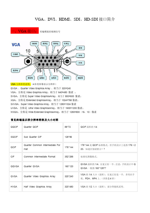
VGA、DVI、HDMI、SDI、HD-SDI接口简介一、VGA接口:传输模拟的视频信号VGA分辨率的说明:(4:3的屏幕显示分辨率)QVGA :Quarter Video Graphics Array ,相当于320×240VGA:全称是Video Graphics Array,相当于640×480 像素 ;SVGA:全称是Super Video GraphicsArray,相当于800×600 像素;XGA:全称是Extended GraphicsArray,相当于1024×768像素;SXVGA:Super Video Graphics Array,相当于1280×1024像素UVGA:全称是 Ultra Video GraphicsArray,相当于1600×1200像素;WXGA:全称是Wide Extended GraphicsArray,相当于1280×800(16:10)像素常见终端显示屏分辨率简称及大小对照QQCIF Quarter QCIF 88*72 QCIF面积的1/4SQCIF Sub Quarter CIF 128*96QCIF Quarter Common Intermediate Format176*144176*144是QCIF标准格式,但手机设计上是指176×220,知道区别请留言??CIF Common Intermediate Format 352*288 标准化图像格式。
QQVGA Quarter QVGA 160*120 QVGA面积的1/4,长宽正好一半,注意:手机设计中Q QVGA一般指160*128??QVGA Quarter Video Graphics Array 320*240 VGA的1/4大小(面积),长宽正好是一半,多用在手机、PDA、MP4上。
(多指2.4屏)HVGA Half Video Graphics Array 320*480 VGA的1/2大小(面积),部分智能机采用。
常用视频接口
常用视频接口我们经常在家里的电视机、各种播放器上,视频会议产品和监控产品的编解码器的视频输入输出接口上看到很多视频接口,这些视频接口哪些是模拟接口、哪些是数字接口,哪些接口可以传输高清图像等,下面就做一个详细的介绍。
目前最基本的视频接口是复合视频接口、S-vidio接口;另外常见的还有色差接口、VGA 接口、接口、HDMI接口、SDI接口。
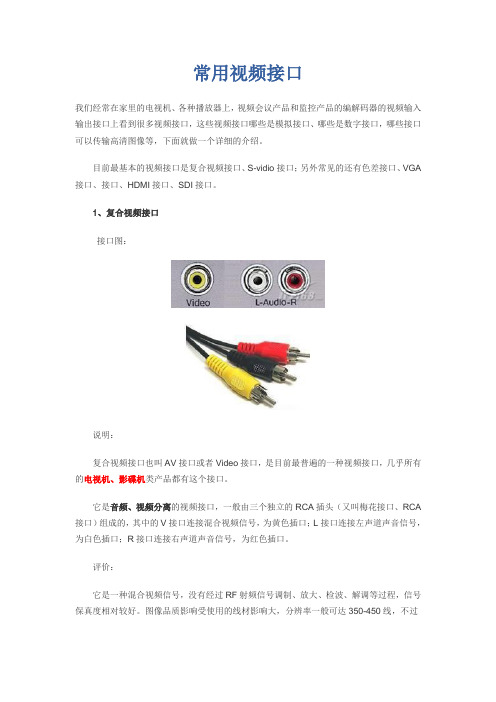
1、复合视频接口接口图:说明:复合视频接口也叫AV接口或者Video接口,是目前最普遍的一种视频接口,几乎所有的电视机、影碟机类产品都有这个接口。
它是音频、视频分离的视频接口,一般由三个独立的RCA插头(又叫梅花接口、RCA 接口)组成的,其中的V接口连接混合视频信号,为黄色插口;L接口连接左声道声音信号,为白色插口;R接口连接右声道声音信号,为红色插口。
评价:它是一种混合视频信号,没有经过RF射频信号调制、放大、检波、解调等过程,信号保真度相对较好。
图像品质影响受使用的线材影响大,分辨率一般可达350-450线,不过由于它是模拟接口,用于数字显示设备时,需要一个模拟信号转数字信号的过程,会损失不少信噪比,所以一般数字显示设备不建议使用。
2、S-Video接口接口图:说明:S接口也是非常常见的接口,其全称是Separate Video,也称为SUPER VIDEO。
S-Video连接规格是由日本人开发的一种规格,S指的是“SEPARATE(分离)”,它将亮度和色度分离输出,避免了混合视讯讯号输出时亮度和色度的相互干扰。
S接口实际上是一种五芯接口,由两路视亮度信号、两路视频色度信号和一路公共屏蔽地线共五条芯线组成。
评价:同AV 接口相比,由于它不再进行Y/C混合传输,因此也就无需再进行亮色分离和解码工作,而且使用各自独立的传输通道在很大程度上避免了视频设备内信号串扰而产生的图像失真,极大地提高了图像的清晰度。
但S-Video仍要将两路色差信号(Cr Cb)混合为一路色度信号C,进行传输然后再在显示设备内解码为Cb和Cr进行处理,这样多少仍会带来一定信号损失而产生失真(这种失真很小但在严格的广播级视频设备下进行测试时仍能发现) 。
SDI与HDMI接口技术知识详析word精品文档4页
SDI与HDMI接口技术知识详析随着广播电视技术的飞速发展,数字电视时代的到来,作为广播电视人的我们亲身经历并见证了,采、编、播信号制播工作流程中所有设备从模拟到数字、从标清到高清的更新换代。
人们在充分地享受着高新的多媒体显示技术和传输技术给他们带来的越来越高质量的视听胜宴之余,有几个人能知道这背后的变革。
作为专业人士的我们又有几个深入地了解了电视数字时代产生了哪些新的应用技术。
下面我将在匆匆胜任数字电视播出工作之余,学习掌握的与显示技术发展结伴而行的显示接口技术HDMI、SDI 接口的相关知识与大家交流学习。
一、SDI数字分量串行接口SDI接口是数字分量串行接口(serial digital interface)的首字母缩写。
串行接口是把数据字的各个比特以及相应的数据通过单一通道顺序传送的接口。
由于串行数字信号的数据率很高,在传送前必须经过处理。
人们常在SDI信号中嵌入数字音频信号,也就是将数字音频信号插入到视频信号的行、场同步脉冲(行、场消隐)期间与数字分量视频信号同时传输。
SDI又分为标清SD-SDI和高清HD-SDI接口标准。
目前高清晰度数字电视制作设备之间的主要连接方式是串行数字分量接口HD-SDI。
(1)SD-SDI 符合SMPTE259-C 标准,嵌入音频符合SMPTE272M标准。
?码率为270Mbps。
(2)HD-SDI 符合SMPTE-292M标准,嵌入音频符合SMPTE299M标准。
?码率为1485Mbps。
我们知道模拟信号(也叫连续信号)经过抽样、量化后变成在时间和幅度上都不连续的信号(也叫离散信号),这样的信号还不是数字信号,需要把离散信号转换成数字符号(如自然二进制码),这种码流是没有经过编码压缩的基带信号,码率较大,占用较大的传输带宽,这种码流的传输接口是SDI接口,也叫串行数字接口,它属于信道码流,所以SDI传输的是采样量化后没有压缩的数字视频信号(也可以把音频嵌入进去)。
SDI接口和HDMI

地铁PIS系统SDI接口和HDMI 接口应用专题研究报告(这是为地铁工程所做,引用请注明出处)一、目前流行的高清数字接口目前流行的高清数字接口有两大类:被广播电视业界、通信业界所接受的SDI (HD-SDI)接口,被电子类消费产品产业界、PC界所接受的HDMI接口和DP接口,分别代表了当今各行业的技术水平。
(一)SDI接口SDI(Serial Digital Interface)全称为“串行数字接口”,是指用于实现电影、广播电视数字化,而将符合SMPTE(电影和电视工程师协会)标准的基带数字视音频信号通过一条电缆进行传输的技术。
1982年,原国际无线电咨询委员会(CCIR)以欧洲广播联盟(EBU)与美国电影和电视工程师协会(SMPTE)的相关提案为基础,发布了CCIR 601号建议书,以13.5 MHz的取样频率、8bit量化技术以及4:2 :2色度亚取样实现了525/60和625/50两种电视扫描系统的数字化。
1986年,CCIR以EBU Tech 3246与SMPTE 125M标准为基础发布了CCIR 656建议书,提出了一种可以传输CCIR 601规格信号的并行接口,使用11对双绞线与25针D型连接器,部分早期数字设备曾使用这种接口,但因传输距离较短、连接较复杂等原因,不适合大规模使用。
其实,CCIR 656还包含了EBU于1983年提出的Tech 3247串行数字接口标准,采用8/9分组编码,比特率为243 Mb/s。
但只支持8比特量化,而且不容易设计出稳定、廉价的接口芯片。
1993年,CCIR成为国际电信联盟(ITU, International Telecommunication Union)的无线电通信部(ITU-R)。
1994年,1TU-R发布了BT 656-2建议书,吸纳了EBU Tech 3267与SMPTE 259M中定义的新型串行数字接口,该接口采用10比特传输与非归零反向(NRzl)编码。
MINI 3G SDI to HDMI 转换器说明书
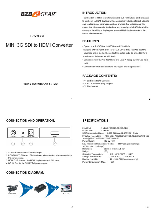
1MINI 3G SDI to HDMI Converter2INTRODUCTION:FEATURES:34The MINI SDI to HDMI converter allows SD-SDI, HD-SDI and 3G-SDI signals to be shown on HDMI displays while ensuring high bit rates of 2.970 Gbit/s to give you fast signal transmission without any loss. For professionals this means that it is now easier to distribute and extend your 3G SDI signal while giving you the ability to display your work on HDMI displays thanks to the built-in HDMI converter.PACKAGE CONTENTS:CONNECTION DIAGRAM:SPECIFICATIONS:CONNECTION AND OPERATION:● 1× 3G SDI to HDMI Converter ● 1x 5V DC Power Supply Adaptor ● 1× User Manual1. SDI IN: Connect the SDI source output.2. POWER LED: This red LED illuminates when the device is conne c ted with the power supply.3. HDMI OUT: Connect the HDMI display with an HDMI cable.4. DC IN: Port for the 5V-12V DC power supply.Input Port: 1 x BNC (SDI/HD-SDI/3G-SDI)Output Port: 1 x HDMISDI Transmission Rates: 2.970 Gbit/s and 2.970/1.001 Gbit/sIn/Output Resolution: 480i, 576i, 720p@50/59.94,60,1080i@50/59.94/60 ***********/24/25/29.97/30/50/59.94/60Power Supply: DC 5V -12VESD Protection Human body model: ±8kV (air-gap discharge) ±4kV (contact discharge)Dimension: 80mm x 41mm x 25 mm Weight: 150gOperating Temperature: 0°C ~ 40°C / 32°F ~ 104°F Storage Temperature: -20°C ~ 60°C / -4°F ~ 140°F Relative Humidity: 20 ~ 90% RH (Non-condensing)Power Consumption (Max): 5W• Operation at 2.970Gbit/s, 1.485Gbit/s and 270Mbits/sSupports SMPTE 425M, SMPTE 424M, SMPTE 292M, SMPTE 259M-C • Equalized and re-clocked loop output Integrated audio de-embe dder for a maximum of 8 channel, 48 KHz Audio• Conversion from SMPTE 425M level B to Level A 1080p 50/59.94/60 4:2:2 10-bit• Connect with other units to extend your signal over long distancesBG-3GSHQuick Installation Guide56WARRANTY:MISSION STATEMENT:BZBGEAR manifests from the competitive nature of the audiovisual industry to innovate while keeping the customer in mind. AV solutions can cost a pretty penny, and new technology only adds to it. We believe everyone deserves to see, hear, and feel the advancements made in today’s AV world without having to break the bank. BZBGEAR is the solution for small to medium-sized applications requiring the latest professional products in AV. We live in a DIY era where resources are abundant on the internet. With that in mind, our team offers system design consultation and expert tech support seven days a week for the products in our BZBGEAR catalog. You’ll notice comparably lower prices with BZBGEAR solutions, but the quality of the products is on par with the top brands in the industry. The unparalleled support from our team is our way of showing we care for every one of our customers. Whether you’re an integrator, home theater enthusiast, or a do-it-yourselfer, BZBGEAR offers the solutions to allow you to focus on your project and not your budget.BZBGEAR wants to assure you peace of mind. We're so confident in the quality of our products that along with the manufacturer's one-year limited warranty, we are offering free second-year warranty coverage upon registration*!Taking advantage of this program is simple, just follow the steps below:1. Register your product within 90 days of purchase by visiting /warranty.2. Complete the registration form. Provide all necessary proof of purchase details, including serial number and a copy of your sales receipt.Forquestions,**************************************************.For complete warranty information, please visit /warranty or scan the QR code below.*Terms and conditions apply. Registration is required.。
索思锐SDI HDMI有线 无线HD视频编码器 2020 版 快速上手指南说明书

Connect one end of the network cable to the encoder Ethernet port. The other end is connected to the network switch or the computer'sUsing the power adapter (DC 12v) connect to the main product, after the power is turned on, then the product starts working immediately.Connect WiFi antenna(for wireless encoder only) Connect the WiFi antenna with the device antenna interface.101112Connect WIFI(for wireless encoder only)07Quick reset and rebootFirmware upgradingRestore factory settingsHold the ‘Reset’ button more than 5 seconds, restoring factory setting will lead to the device reboot, and restarting course will last about 20s.NOTE:These parameters will be restored after restoring factory setting:● Login username and password will be as admin;IP address will be restored as 192.168.1.168, subnet mask will be ● 255.255.255.0;All encoding parameters of video and audio will be restored to factory ● default value;Media transmission parameters will be restored as factory default value.●Restore factory settingsTwo methods for restoring factory settings:If users change parameters that lead encoder couldn’t work(The typical situation is changed network address, so it couldn’t be visited encoder by network), users could restore factory setting to default value.①Choose”Basic Settings>Restore factory settings”on the web console.②Press “Reset” button.Firmware upgradingThis device supports online firmware upgrading for upgrading software. Select”Basic Settings”, pull downward and click”Update firmware ”.On the page, click”Browse” to select the upgrading file, and click”Upgrade” to upgrade the device.NOTE:After uploading firmware file successfully, the encoder will automatically restart, this process will take about 30s-60s(the time will be different according to upgrade content), and please be patient.After the upgrade is complete, via the web interface”system information>versioninformation” to check whether the latest version information in accordance with expected and confirm the upgrade succeeded.Quick reset and Reboot“Quick Reset” function is to reset encoding service, normally used for making changed parameters to effect immediately. The whole process lasts around 3s.“Reboot” function is used for encoder reboot. Device rebooting lasts around 20s.NOTE:Select”Quick Reset”,current encoding will be suspended for a while;Select”Reboot”, the encoder will ‘warm’ reboot.Under some circumstances, reboot maybe with the help of ‘cold’ reboot:power down then power up the device.①Click web management interface”Network&Service Settings-Network manager”②Click “Configuration” under wifi for Wifi setting interface③Users could configure according to the related parameters of Wifi hotspots. Put in password, after succeed, it could transmit through wireless network.Note:When using the encoder Wifi function, don't connect to the wired network or optionally delete the gateway address of the wired network. Because the wired network priority is higher than Wifi, the simultaneous connection may cause the WiFi network to push stream unsuccessfully.Coding and pushing08Encoder supports H.264 encoding, support a variety of push-flow methods, such as RTP, RTMP, RTMPS, UDP, HLS, etc.The RTSP services is always enable for the device , all tools which support the standard RTSP protocol and H.264 decoding (such as VLC media player) can be connected to the encoder and get video streams.Main: rtsp://encoder IP address:554/ch01SUB: rtsp://encoder IP address:554/sub01Note:”ch01”, ”sub01” is the RTSP session ID.You can change the session ID in the Web console.The default RTSP accessing URL is:The following is an example of RTMP to introduce the configuration of push flow. Other push flow methods can be login to the device page for detailed configuration.RTMP Live Streaming09Add RTMP pushing streaming serviceAdd streaming serviceOur device’s H.264 main/sub stream supports adding up to 8 same or different streaming media service, to meet your needs of adopting same/different stream media protocols for multi-goal pushing.On the management interface of “Encoding&Stream-Encoding and Stream Settings”, for main/sub stream to choose “add one stream service”, users can add the needed service type.Currently main video live streaming platforms require”RTMP” service. After adding RTMP pushing service, click set icon to configure RTMP parameters.Take YouTube for an example“Streaming point” is RTMP address given by platform ( Take YouTube as an example ). ( Other platforms are similar, if questions please contact platform technical support for help ).RTMP push-flow must first get a push-flow URL address from the platform Login to YouTube, got below address:Streaming point should be like Server URL+Stream name/key,for example: rtmp:///live2/9ja6-9u28-uz4j-8x6rAfter you get the RTMP URL address, you need to set it up in the encoder. If the platform requires user name and password verification, you also need to fill in the corresponding parameters in the encoder.In the case of rtmps push mode, fill in rtmps URL at Push point and set Use old RTMP version to yes, so that it can be supported.NOTE:。
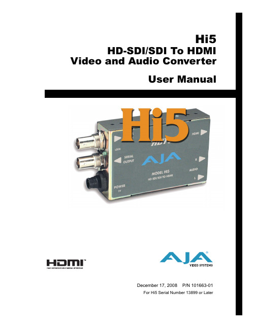
AJA Video Hi5 HD-SDI SDI To HDMI 视频和音频转换器用户手册说明书
TrademarksAJA ® , KONA ® , and XENA ® are registered trademarks of AJA Video, Inc. Io HD ™ and Io ™ are trademarks of AJA Video, Inc. HDMI, the HDMI logo and High-Definition Multimedia Interface are trademarks or registered trademarks of HDMI Licensing LLC. DVI is a registered trademark of DDWG. All other trademarks are the property of their respective holders.NoticeCopyright © 2008 AJA Video, Inc. All rights reserved. All information in this manual is subject to change without notice. No part of the document may be reproduced or transmitted in any form, or by any means, electronic or mechanical, including photocopying or recording, without the express written permission of AJA Inc.FCC Emission InformationThis equipment has been tested and found to comply with the limits for a Class A digital device, pursuant to Part 15 of the FCC Rules. These limits are designed to provide reasonable protection against harmful interference when the equipment is operated in a commercial environment. This equipment generates, uses and can radiate radio frequency energy and, if not installed and used in accordance with the instruction manual, may cause harmful interference to radiocommunications. Operation of this equipment in a residential area is likely to cause harmful interference in which case the user will be required to correct the interference at his own expense. Changes or modifications not expressly approved by AJA Video can effect emission compliance and could void the user’s authority to operate this equipment.Contacting SupportTo contact AJA Video for sales or support, use any of the following methods:443 Crown Point Circle, Grass Valley, CA. 95945 USA Telephone: 800.251.4224 or 530.274.2048Fax: 530.274.9442Web: SupportEmail:***************SalesEmail:*************When calling for support, have all information at hand prior to calling.Limited WarrantyAJA Video warrants that this product will be free from defects in materials and workmanship for a period of five years from the date of purchase. If a product proves to be defective during this warranty period, AJA Video, at its option, will either repair the defective product without charge for parts and labor, or will provide a replacement in exchange for the defective product.In order to obtain service under this warranty, you the Customer, must notify AJA Video of the defect before the expiration of the warranty period and make suitable arrangements for the performance of service. The Customer shall be responsible for packaging and shipping the defective product to a designated service center nominated by AJA Video, with shipping charges prepaid. AJA Video shall pay for the return of the product to the Customer if the shipment is to a location within the country in which the AJA Video service center is located. Customer shall be responsible for paying all shipping charges, insurance, duties, taxes, and any other charges for products returned to any other locations.This warranty shall not apply to any defect, failure or damage caused by improper use or improper or inadequatemaintenance and care. AJA Video shall not be obligated to furnish service under this warranty a) to repair damage resulting from attempts by personnel other than AJA Video representatives to install, repair or service the product, b) to repair damage resulting from improper use or connection to incompatible equipment, c) to repair any damage or malfunction caused by the use of non-AJA Video parts or supplies, or d) to service a product that has been modified or integrated with other products when the effect of such a modification or integration increases the time or difficulty of servicing the product.THIS WARRANTY IS GIVEN BY AJA VIDEO IN LIEU OF ANY OTHER WARRANTIES, EXPRESS OR IMPLIED. AJA VIDEO AND ITS VENDORS DISCLAIM ANY IMPLIED WARRANTIES OFMERCHANTABILITY OR FITNESS FOR A PARTICULAR PURPOSE. AJA VIDEO’S RESPONSIBILITY TOREPAIR OR REPLACE DEFECTIVE PRODUCTS IS THE WHOLE AND EXCLUSIVE REMEDY PROVIDED TO THE CUSTOMER FOR ANY INDIRECT, SPECIAL, INCIDENTAL OR CONSEQUENTIAL DAMAGES IRRESPECTIVE OF WHETHER AJA VIDEO OR THE VENDOR HAS ADVANCE NOTICE OF THE POSSIBILITY OF SUCH DAMAGES.AJA Hi5 HD-SDI/SDI to HDMI and Audio Converter User Manual — Introduction IntroductionFeaturesBlock DiagramI/O ConnectionsHi5 ConverterUser ControlsAn internal Jumper block with 3 jumpers (J4) provides controls for HDMI audio, SD/HD-SDI InputOutput2 Channel BNC LoopOutput+ 5VDC Power InputHDMI ConnectorUnbalanced Analog Audio(RCA Jacks)AJA Hi5 HD-SDI/SDI to HDMI and Audio Converter User Manual — InstallationInstallationSpecifications。
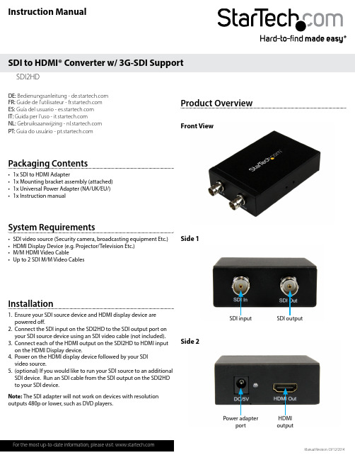
星辰科技 SDI2HD 3G-SDI 支持 SDI 到 HDMI 转换器说明书
Instruction ManualDE: Bedienungsanleitung - FR: Guide de l'utilisateur - ES: Guía del usuario - IT: Guida per l'uso - NL: Gebruiksaanwijzing - PT: Guia do usuário - Manual Revision: 03/12/2014Packaging Contents• 1x SDI to HDMI Adapter • 1x Mounting bracket assembly (attached) • 1x Universal Power Adapter (NA/UK/EU/) • 1x Instruction manualSystem Requirements• SDI video source (Security camera, broadcasting equipment Etc.)• HDMI Display Device (e.g. Projector/Television Etc.)• M/M HDMI Video Cable • Up to 2 SDI M/M Video CablesSDI2HD SDI to HDMI® Converter w/ 3G-SDI SupportInstallation1. Ensure your SDI source device and HDMI display device are powered off.2. Connect the SDI input on the SDI2HD to the SDI output port on your SDI source device using an SDI video cable (not included).3. Connect each of the HDMI output on the SDI2HD to HDMI input on the HDMI Display device.4. Power on the HDMI display device followed by your SDI video source.5. (optional) If you would like to run your SDI source to an additional SDI device. Run an SDI cable from the SDI output on the SDI2HD to your SDI device.Product Overview Front View Side 1Side 2Power adapter port HDMI output SDI input SDI output Note: The SDI adapter will not work on devices with resolution outputs 480p or lower, such as DVD players.FCC Compliance StatementThis equipment has been tested and found to comply with the limits for a Class B digital device, pursuant to part 15 of the FCC Rules. These limits are designed to provide reasonable protection against harmful interference in a residential installation. This equipment generates, uses and can radiate radio frequency energy and, if not installed and used in accordance with the instructions, may cause harmful interference to radio communications. However, there is no guarantee that interference will not occur in a particular installation. If this equipment does cause harmful interference to radio or television reception, which can be determined by turning the equipment off and on, the user is encouraged to try to correct the interference by one or more of the following measures:• Reorient or relocate the receiving antenna.• Increase the separation between the equipment and receiver.• Connect the equipment into an outlet on a circuit different from that to which the receiver is connected.• Consult the dealer or an experienced radio/TV technician for help.Use of Trademarks, Registered Trademarks, and other Protected Names and SymbolsThis manual may make reference to trademarks, registered trademarks, and other protected names and/or symbols of third-party companies not related in any way to . Where they occur these references are for illustrative purposes only and do not represent an endorsement of a product or service by , or an endorsement of the product(s) to which this manual applies by the third-party company in question. Regardless of any direct acknowledgement elsewhere in the body of this document, hereby acknowledges that all trademarks, registered trademarks, service marks, and other protected names and/or symbols contained in this manual and related documents are the property of their respective holders.Technical Support’s lifetime technical support is an integral part of our commitment to provide industry-leading solutions. If you ever need help with your product, visit /support and access our comprehensive selection of online tools, documentation, and downloads.For the latest drivers/software, please visit /downloadsWarranty InformationThis product is backed by a one year warranty. In addition, warrants its products against defects in materials and workmanship for the periods noted, following the initial date of purchase. During this period, the products may be returned for repair, or replacement with equivalent products at our discretion. The warranty covers parts and labor costs only. does not warrant its products from defects or damages arising from misuse, abuse, alteration, or normal wear and tear.Limitation of LiabilityIn no event shall the liability of Ltd. and USA LLP (or their officers, directors, employees or agents) for any damages (whether direct or indirect, special, punitive, incidental, consequential, or otherwise), loss of profits, loss of business, or any pecuniary loss, arising out of or related to the use of the product exceed the actual price paid for the product. Some states do not allow the exclusion or limitation of incidental or consequential damages. If such laws apply, the limitations or exclusions contained in this statement may not apply to you.Specifications。
HyperDeck Studio参数
Blackmagic HyperDeck Studio1,主要规格设备种类:硬盘录像机视频输入格式:SDI,HDMI视频输出格式:SSDI,HDMI音频采样:电视标准采样率48kHz,24bit量化2,功能特效SDI视频输入:1*10-bit,兼容SD/HD/3Gb/s SDISSDI视频输出:2*10-bit,兼容SD/HD/3 Gb/s SDI;1*10-bit,兼容SD/HD/3Gb/s SDI,环通输出;1*10-bit,兼容SD/HD/3Gb/s SDI,监视器输出HDMI视频输入:1*HDMI 1.3A型接口HDMI视频输出:1*HDMI 1.3A型接口SDI音频输入:高清和标清时,支持16通道内嵌音频SDI音频输出:高清和标清时,支持16通道内嵌音频HDMI音频输入:高清和标清时,支持8通道内嵌音频HDMI音频输出:高清和标清时,支持2通道内嵌音频同步输入:黑场和三电平3,其他参数设备控制:Sony可兼容RS422录机遥控端口录像机控制:利用HyperDeck Studio自带得12个按钮和Jog搜索轮控制,或通过RJ45以太网或USB2.0接口进行控制录像机配置:通过USB2.0接口进行配置SSD接口:2*2.5”SATA 3Gb/sSDI标准:SMPTE 259M、SMPTE 292M多码流支持:SDI和HDMI支持270Mb/s的SD-SDI和1.5Gb/s HD-SDI视频采样:4:2:2色彩精度:10-bit色彩空间:REC 601、REC 709SDI元数据:HD RP188和CC字幕追问它的录制格式都有哪些的?回答HyperDeck Studio Pro之前已经支持无压缩、ProRes 422(HQ)和DNxHD格式的记录和回放。
现在还可以选用另外三种ProRes格式,即ProRes 422、ProRes 422(LT)和ProRes 422(Proxy)。
这些新加入的格式极大地缩小了视频文件尺寸,但是仍然保有全帧10-bit 4:2:2质量。
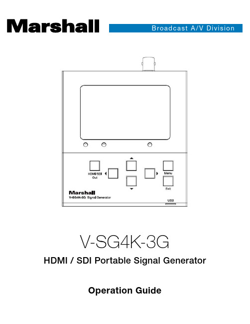
马尔杜·USA V-SG4K-3G HDMI SDI可移动信号生成器用户操作指南说明书
st A /V DOperation GuideV-SG4K-3GHDMI / SDI Portable Signal GeneratorV-SG4K-3G ManualTable of ContentsTable of Contents 8. Software - PC Control App4. Specifications 2. Features6. Quick Start and System Check 1. Introduction 9. Software - Test Pattern Uploader App 10. Troubleshooting11. Warranty & Contact Information5. Package Contents3. Controls and Connections 7. Menu Operations010906030702182021060407 1. IntroductionThe V-SG4K-3G is a programmable SD/HD/3G-SDI and HDMI HD/UHD Test Pattern Generator, packed with features for video and audio testing of SDI and HDMI monitors, processors, and recorders. The compact and portable V-SG4K-3G generates a full range of resolutions with a maximum of 4K (UHD) at 60Hz, with 4:2:0 signal, making it a “must have” tool for AV Systems Integrators and installers. An internal audio tone generator as well as an external stereo input allows embedding of test audio into the SDI or HDMI signals.The V-SG4K-3G can be easily operated from the front panel, with the 3-inch LCD display for additional meny settings, and to indicate the pattern being generated. In addition, remote control is available via USB or RS-232 serial interface. Control and pattern uploader applications are available to download from our website, .V-SG4K-3G Manual2. Features• Useful for quick checks on both HDMI and SDI devices.• Wide range of video formats up to 4Kx2K (UHD) and frame rates up to 60fps as well as specialpatterns for 3D/VR checks.• Supports multiple HDMI sampling structures including RGB4:4:4, YUV4:4:4, YUV4:2:2, andYUV4:2:0.• SDI Output supports SD/HD/3G SDI up to 1080p at 60 fps.• Includes 39 preset patterns plus 4 user-uploadable patterns.• Generates 61 pre-defined resolutions, 10 user-defined resolutions, and 1 auto-sensing HDMImode.• LCD panel provides Pattern preview and Menu settings display.• Supports 7 audio sample rates and 1 auto mode based on the HDMI EDID data from the deviceunder test.• The HDMI Output features multiple setting options including: HDMI/DVI mode, DeepColor mode,HDCP On/Off for compliance checking, “Color Space” selections (sampling structure) and othervideo parameters.• HDMI EDID may be captured from a sink device (monitor, etc.) and stored in the generator. Upto 6 sets of EDID may be stored.• Software for control and User Pattern upload is available on the Marshall Electronics website.1. 3 - inch LCD Panel. Displays current pattern and menus.2. HDMI/SDI mode LED’s. These indicate which output is currently active.3. HDMI/SDI mode switching button. Selects between HDMI output and SDI output.4. Status LED. Provides a quick check of the HDMI link status. (Does not light in SDI mode). The Status LED will be off when the HDMI link is lost or HPD (Hot Plug Detect) signal is not present from sink device. The Status LED blinks if an HDMI EDID error occurs.5. Arrow cluster. The arrow buttons allow quick change of video format (Left or Right arrow) and pattern (Up or Down arrow). These buttons are also used to navigate in the Menu system.6. Menu and Exit buttons. Pressing the Menu button brings the setup menu to appear on the 3-inch display. Pressing Exit cancels the current Menu operation. Use the Left and Right arrows to change menu categories. Use the Up and Down arrows to select desired items. Press Menu to confirm the selection.7. Mini-USB connector. Allows connection to a PC for external control. (Note: This is not a power port.)Front Panel Description3. Controls and ConnectionsV-SG4K-3G Manual1. RS-232 connector for PC control. Provides an alternative to the USB connection for control from a PC.2. SDI Output BNC connector.3. Stereo Audio Input connector (3.5 mm mini-phone). Allows embedding of custom audio into the HDMI or SDI video output.4. HDMI Output / EDID capture connector.5. 5-Volt DC Power connector. Note: Please use only 5-volt power sources, center pin positive. Similar-looking 12-volt power supplies are common and may damage the unit if connected.Rear Panel Description4. Specifications5. Package Contents• Main Unit: V-SG4K-3G •5-Volt 2 Amp Power SupplyV-SG4K-3G Manual6. Quick Start and System Check7. Menu Operations1. Connect 5-volt power to the V-SG4K-3G. A pattern should appear on the 3-inch display and at least one LED should light.2. Connect an HDMI cable from the V-SG4K-3G to a UHD monitor or other HDMI “sink” device.3. Press the HDMI/SDI Output button to light the HDMI LED. The current test pattern should appear on the attached monitor or other connected device unless the current signal format is not supported by that device.4. Press Left or Right arrow buttons to change Video Format. Press Up or Down arrow buttons to change Test Pattern.5. Suggestion: At this point, you may wish to take a moment to scroll through some of the patterns and video formats to explore what is available with the V-SG4K-3G test generator.More adjustments and settings are available by pressing the MENU button. Depending on the current output mode (HDMI or SDI ), menu categories may change. For example: here are two versions of the Timing Resolution menu.SDI Mode HDMI ModeTo change settings in the Menus, use the Left or Right arrow buttons to select categories. Use the Up or Down arrow buttons to select an item within a category. Press the Menu button to confirm an item or press the Exit button to leave the menu without making a change.Menu Categories (HDMI Mode):• Timing Resolution. Select from 44 picture formats and frame rates such as 1080p at 59.94 fps, 720p at 50 fps, 1080i at 50 fps, 17 3-D formats, 10 User-Defined formats, as well as AUTO mode. Video and Computer Graphic formats are supported.• Color Space. Select color components and sampling structure such as RGB444, YUV422. AUTO mode polls the EDID information from the connected device and sets the generator to match.• Deep Color Depth. Selects the bit depth of the generated signal from 8-bits up to 16-bit video. AUTO mode polls the EDID information from the connected device and sets the generator to match.• HDCP Setting. Turn the HDCP flag ON or OFF. When HDCP is ON, the test signal will only appear on displays or projectors and only those that are HDCP compliant. This provides a quick way to confirm HDCP compliance.• HDMI / DVI Setting. In DVI mode, the HDMI output is limited to the feature set that is supported by the DVI standard. Useful for testing when an HDMI -to-DVI adapter cable is being used. AUTO mode tests the interface and selects the matching mode.• Audio Sampling Rate. Selects the sampling rate for the embedded audio. Choices are available from 32kHz to 192kHz. AUTO mode selects the best rate based on HDMI EDID data.• Audio Sampling size. Selects the audio bit depth from 16- to 24-bits. AUTO mode selects the maximum bit depth based on the HDMI EDID data.• Audio Source. Selects the audio that will be embedded in the video output. Internal tones of 1, 2, or 4kHz are available or external stereo audio from a line-level analog source can be selected. • Audio Channels. Various audio embedding arrangements can be selected from simple 2-channel stereo to 7.1-channel surround. (8 embedded channels). When external audio is used, only channels 1 and 2 will be embedded.• Audio Volume. Adjust the volume of the embedded audio here. The default setting is 10 (maximum) which produces 0dBm output. Each volume step is 6dB so, for example, 3 steps down to 07 equates to -18dB output. (EBU reference level).• Signal Output. Turn the Video output ON or OFF.• Save EDID. Reads EDID information from an attached HDMI device and saves it in the generator. Up to 6 sets of EDID data may be saved.• Sink EDID Info. Displays basic information about the attached HDMI device such as the Manufacturer name, Preferred Timing (preferred resolution and frame rate), Audio capabilitiesand more.V-SG4K-3G ManualMenu Categories (SDI Mode):• Timing Resolution. Select from 16 preset picture formats and frame rates such as 1080p at59.94 fps, 720p at 50 fps, 1080i at 50 fps. Only SDI compliant formats are provided.• Audio Source. Selects the audio that will be embedded in the video output. Internal tones of 1, 2, or 4kHz are available or external stereo audio from a line-level analog source can be selected.• Audio Channels. Various audio embedding arrangements can be selected from simple 2-channel stereo to 8 channels. When external audio is used, only channels 1 and 2 will be embedded.• Audio Volume. Adjusts the volume of the embedded audio. The default setting is 10 (maximum) which produces 0dBm output. Each volume step is 6dB so, for example, 3 steps down to 07 equates to -18dB output. (EBU reference level).• Signal Output. Turn the video output ON or OFF.8. Software - PC Control AppControlling the V-SG4K-3G from a computer:A Windows® application is available for free download from the Marshall Electronics website here:/racks/TestMeasurement/V-SG4K-3G.phpThis application provides detailed control of all menu functions plus adjustment of many parameters not in the Menus. The V-SG4K-3G may be operated via USB or RS-232 serial link.• USB Connection: Use only type A to mini-USB cable• RS-232 Connection assuming standard 9-pin connector:• Pin 2 Rx to Signal Generator Tx• Pin 3 Tx to Signal Generator Rx• Pin 5 Ground to Signal Generator(If “null modem” cable or adapter is in use, connection of Pin 2 and 3 should be reversed)Quick Start and Operational Check1. Copy app file to a convenient place such as the Desktop. Double click to open the app. It should run immediately without any installation needed.2. Connect a mini-USB cable between the generator and the PC. (The PC will establish a “Comm Port” connection at this time. Normally, this takes a few seconds but should not take longer than 1 or 2 minutes the first time.)3. Click the “Search Device” button (see figure below). The Activity icon will light Red if step 2 was successful.4. Try selecting SDI then HDMI. The HDMI & SDI LED’s on the unit should follow these selections. (If you experience problems making a USB connection, please see Troubleshooting section.) Main Screen Showing Current StatusAreas on the left of this screen show key information such as status of the link between the generatorand PC as well as generator operating modes.V-SG4K-3G ManualSDI Timing OptionsTiming TabThe Timing Tab allows quick access to all available video formats and frame rates. The figureIn SDI mode, the choices available are those labeled “Video Standards.”below shows the HDMI choices. Simply click on any of the choices to change the video output.HDMI Timing OptionsV-SG4K-3G ManualTiming Details TabThis page is useful for product development and QC. Non-standard timings may be entered here and stored for later retrieval with the “Save to Userdefine Timing” button. The “UpdateStatus” button sends the new timing settings to the V-SG4K-3G.Pattern Selection TabThis page allows quick selection of any available test pattern including four User-Defined patterns. (User-Defined patterns do not have icons). User-Defined patterns are uploaded to theV-SG4K-3G using the Pattern Uploader application.Note that the “Pathological” pattern is available only in SDI mode as it is specifically designed for testing SDI interfaces.V-SG4K-3G ManualSetting TabThis page contains a collection of settings for video and audio.Note that the choice for YUV 4:2:0 is available only when the generator is in HDMI mode and a UHD 50, 59.94 or 60 fps pattern is selected. In this mode, the signal generated is compatible with HDMI EDID TabThis page allows testing HDMI EDID (Extended Display Identification Data). It has no application for SDI interfaces.EDI D is a set of information stored in a display device (monitor or projector) by the display manufacturer. In normal operation, this information is retrieved by a source device such as a set top box, media player, etc. when it is connected or powered on. EDID is intended to allowa source device to change its settings to match the display device. This process is invisible tothe user.The V-SG4K-3G Test Pattern generator allows inspection of this EDID information to help with trouble shooting, product development, equipment test and QC.Using the EDID functionClick on the READ EDID button to capture EDID data directly from a connected display device when the window below the button says “TV EDID”. Also, EDID data that has been previously captured and saved in the V-SG4K-3G may be accessed by selecting “Saved 1 – 6” in the pulldown window below the button.The EDID information is organized in three zones on the page:General Info – Details about the manufacturer and specifications.Video Information – A list of all video formats, frame rates, and standards that will be compatible with the device.Audio Information – A list of all audio formats and standards that will be compatible with the device. There is generally a lot of information in these windows. It may be necessary to scroll through the information to see all the possible options.Information from the READ EDID function may be stored on the local PC by clicking on the SAVE EDID button. Each time SAVE EDID is clicked, a pair of files is saved to the PC. The files are saved to the same location as the Control Application. EDID saved files are automatically named and numbered sequentially and appear like this:SigGen_EDID02.binSigGen_EDID02.txtV-SG4K-3G ManualThere is no limit to the number of EDID files that can be saved on a PC. Files may be renamed for convenience as long as the “.bin” and “.txt” extensions are not changed. For example, the two files above may be renamed something like:BigMonitor1.bin BigMonitor1.txtFiles saved on a PC may be opened later for more analysis by clicking on the OPEN EDID button and browsing to the file.Note: The WRITE EDID button does not apply to the V-SG4K-3G signal generator and remains “grayed out.”9. Software - Pattern Uploader AppUploading Test Patterns to the V-SG4K-3G from a computerA Windows® application is available for free download from the Marshall Electronics website here: /racks/TestMeasurement/V-SG4K-3G.phpThe Pattern Uploader application allows the user to install up to 4 custom test patterns into the V-SG4K-3G non-volatile memory.Note: User patterns must be .BMP files with 1920 x 1080 resolution.Pattern Uploader Quick Start and Operational Check1. Copy the app file to a convenient place such as the Desktop. Close the Control Application if it is open and double-click to open the Uploader app. It should run immediately without any installation step needed. The screen below will appear (pattern window will be black).2. Connect the PC to the V-SG4K-3G Test Pattern Generator using a mini-USB cable asdescribed for the Control App.V-SG4K-3G Manual 19203. Click on the “Search for Signal Generator” button. The icon in the upper left corner will change to Red. Pattern uploading is a three-step process:10. TroubleshootingIf you experience difficulties, try these tips:No video out.• Check the HDMI/SDI button.• n the MENU, turn Signal Output ON .• In the MENU, turn HDCP Setting OFF.• Try a different video format / frame rate to find one that is compatible with the device being tested.“EDID Invalid” Message• Try a different HDMI cable. Some cables are not properly configured to test all functions.• Try a different input on the attached device.• Try powering the device Off and B connection not recognized by host PC• Be sure to use a mini-USB cable, not a USB “Micro” cable.• Try reconnecting the cable. This should “wake up” the USB port on the PC. Allow several minutes for the PC to recognize the device and find the correct driver. This is particularly true for Windows 10 which may reach out to the Web to locate a driver. • If the USB interface is not recognized by the PC and you wish to install a driver manually, you may download the latest FTDI driver here:/Drivers/VCP .htmStep 1 – Click on the “Load Image” button. Browse to the desired pattern and click on the file name. An image of the pattern should immediately appear in the pattern window. In the “Use Pattern Number” window, enter a number from 1 – 4.Step 2 – Click on the “SD NAND FLASH” button. The word “Erasing” may appear on the screen if there was a pattern previously stored. When erasing is complete, the uploading progress will appear in the “%” window. Take a break. Depending on the amount of detail in the image, this process can take up to 15 minutes to complete!Step 3 – Click “Search for Signal Generator” then click on the 3-inch LCD Panel Data Flash button. This will immediately load a smaller version of the test pattern which will appear in the 3-inch LCD on the V-SG4K-3G Test Pattern Generator. This process runs very quickly and should complete in under 15 seconds.TIP! You may prefer to do Step 3 before Step 2 to save time.Please Note: An uploaded User Pattern will be available after the V-SG4K-3G has been turned off and back on again.20608 Madrona Avenue, Torrance, CA 90503Tel: (800) 800-6608 / (310) 333-0606 • Fax: 310-333-0688************************J R 02212020a2111. Warranty and Contact InformationThe Marshall V-SG4K-3G Test Pattern Generator will, under normal use, be free from defects in workmanship and materials, when received in its original container, for a period of one year from the purchase date. This warranty is extended to the first consumer only, and proof of purchase is necessary to honor the warranty. If there is no proof of purchase provided with a warranty claim, Manufacturer reserves the right not to honor the warranty set forth above. Therefore, labor and parts may be charged to the consumer. This warranty does not apply to the product exterior or cosmetics. Misuse, abnormal handling, alterations or modifications in design or construction void this warranty. No sales personnel of the seller or any other person is authorized to make any warranties other than those described above, or to extend the duration of any warranties on behalf of Marshall Electronics, beyond the time period described above.Due to constant effort to improve products and product features, specifications may change without notice.。
产品应用-SDI to HDMI+VGA+AV 转换盒 MDIN380

MDIN165
MDIN165
MDIN27 0
方案应用
■ 产品简介
) 视频转换盒 (HD-SDI HD-SDI)
视频转换盒(converter Box) 是视频接口转换的设 备,在家庭应用上 DVD,DV,PSP,Wii,PS3,PC 等 设备,视频接口都不是统一的标准,那就需要用转换 盒来连接到格式各样接口的显示屏上,在视频监控和 广播应用上各种视频源设备亦不是统一的接口标准, 也需要通过转换盒来转换输出接口。 通用视频接口主要有:AV,YPbPr,HDMI,VGA,DVI, DisplayPort,MHL,BNC,HD-SDI 等。任何有视频接 口转换的场合,都需要用到视频转换盒。 本方案基于韩国 MIT 公司的系列芯片可覆盖大部分主 流的接口转换盒应用。
■ 图解
深圳市友邦兴业科技有限公司 / ShenZhen Boomtek Technology Ltd.
地址:深圳市福田区彩田南路 3002 号彩虹大厦 23BC 室 梁生 Mob:13480612865 Tel: 0755-83751315 Fax: 0755-83751715
■ 功能特点
接口高度集成,降低系统方案成本 独到的 iMarv 技术,顶级的图像品质 支持任意分辨率的互转,支持任意尺寸的显示器 业内最好的 3D 降噪和 3D 去隔行技术 单芯片设计,内嵌 DDR 软件开发包架构统一,一代产品,多颗芯片通用 双视频输入,画中画变得简单 强大的 OSD,UI 界面美观时尚 芯片选型表:
sdi接口标准 -回复
sdi接口标准-回复什么是SDI接口标准?SDI(Serial Digital Interface)是一种数字视频接口标准,广泛应用于广播电视和专业视听设备中。
SDI接口标准主要定义了数字视频和音频信号的传输格式和电气特性,旨在实现高质量和可靠的视频传输。
SDI接口标准的发展历史可追溯到上世纪80年代,当时模拟视频转数字视频的需求逐渐增加。
为了实现数字数据的传输和处理,提高视频的质量和稳定性,逐渐产生了SDI接口标准。
SDI接口标准有多个版本,常见的包括SD-SDI、HD-SDI和3G-SDI。
SD-SDI(Standard Definition-SDI)是标清数字视频接口标准,用于传输标清视频信号(如PAL或NTSC格式的视频)。
HD-SDI(High Definition-SDI)是高清数字视频接口标准,用于传输高清视频信号(如720p或1080i格式的视频)。
3G-SDI是超高清数字视频接口标准,支持更高分辨率和更高帧率的视频传输。
SDI接口标准采用基于串行传输的方式,将视频和音频信号转换为数字信号,通过同一根电缆传输。
这种传输方式大大简化了视频设备的连接,提高了传输效率和可靠性。
同时,SDI接口还具备抗干扰能力强、传输距离远等优点,可以满足广播电视和专业视听设备对高质量视频传输的要求。
SDI接口标准定义了视频和音频信号的编码和解码规范,常用的视频编码格式包括Uncompressed、DVCPro、DVCPRO50、DVCPRO100等,音频编码格式包括PCM(脉冲编码调制)和AES/EBU。
此外,SDI接口标准还规定了信号的电气特性,如传输速率、阻抗、电平等,以确保信号的有效传输和兼容性。
SDI接口标准的应用非常广泛。
在广播电视行业,SDI接口被广泛用于摄像机、视频切换器、视频路由器、显示器等设备之间的连接。
在专业视听设备中,SDI接口被用于音视频编辑设备、摄像机监视系统、演播室设备等。
LVDS输出HD-SDI及HDMI接口机芯GVJX20-S
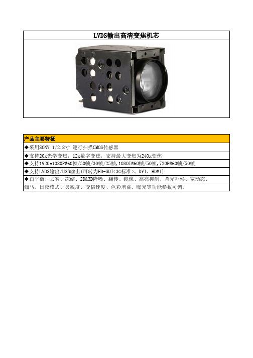
LVDS输出高清变焦机芯产品主要特征◆采用SONY 1/2.8寸 逐行扫描CMOS传感器◆支持20x光学变焦,12x数字变焦,支持最大变焦为240x变焦◆支持1920x1080P@60帧/50帧/30帧/25帧,1080I@60帧/50帧,720P@60帧/50帧◆支持LVDS输出/USB输出(可转为HD-SDI<3G标准>、DVI、HDMI)◆白平衡、去雾、冻结、2D&3D降噪、翻转、镜像、高亮抑制、背光补偿、宽动态、伽马、日夜模式、灵敏度、变倍速度、色彩增益、曝光等功能参数可调。
类型插针编号名称有效像素1TXOUT3+2TXOUT3-3TXCLKOUT-4TXCLKOUT+5TXOUT3+6TXOUT3-7TXOUT3+8TXOUT3-9TXOUT3+10TXOUT3-11GND 14DC IN 15DC IN 16DC IN 17DC IN 18DC IN 19GND 20GND 21GND 22GND 23GND 24GND 25NC 26NC像素尺寸图像尺寸电平30PIN针脚定义针脚定义技术规格机芯组件SONY 1/2.8英寸 逐行CMOS 16:9 逐行扫描扫描系统20 倍光学放大约210万像素2.8um x2.8um 1920x1080,1080x720图像传感器F=4.7mm(广角端)~94mm(远端)F1.8 ~ F3.5镜头数字变焦聚焦范围.最小物距12倍(使用光学变焦后为240倍)100mm(广角), 1000mm(近角)水平:58.7°(广角),3.2°(近角)视场角最低照度同步系统0.5Lux (白天)0.1Lux (夜晚)内同步Wide~Tel :3.0S Tel~Wide :2.8S变焦速度1920x1080p@50,60有数字输出接口像素/帧率图像输出1920x1080p@25,301920x1080i@50,601280x720p@50,60ITU-R BT.1120 (YcbCr4:2:216bits)UART(3.3V level)(2 选 1)SONY-VISCA协议,8bitsdata, 1 stop bitPelco-D协议,8bits data, 1stop bit通信方式 6.0V-12.0V 直流6.0V-12.0V 直流6.0V-12.0V 直流6.0V-12.0V 直流6.0V-12.0V 直流12TxD RxD13CMOS 5V(低:Max 0.1V 高:Min 4.4V)CMOS 5V(低:Max 0.8V 高:Min 2.0V)组件性能彩转黑 15-126,111级可选亮度0-15,15级可选去雾1-15,15级可选宽动态1-6,6级可选色饱和度0-15,15级可选背光补偿 有高亮抑制 有黑转彩5-190,185级可选隐私遮挡有日夜模式自动/日/夜/外同步镜像有增益限制 2/4/6/8/11/16/32/64/128/256/320/511预设位有翻转有冻结有伽马0-5,5级可选降噪2D降噪/3D降噪锐度0-15,15级可选对比度0-15,15级可选手动/键控/自动,20cm/1M/2M/3M/5M AE控制自动/手动/光圈优先/快门优先/亮度优先 增益 0-15,15级可选光圈 0-13,13级可选聚焦控制产品尺寸88x50x60 mm产品净重电子快门速度1/50,1/100,1/120,1/150,1/500,1/1K,1/4K,1/10K白平衡自动/室内/室外/键控/自动跟踪/手动/钠灯/日光波特率2400/4800/9600/19200/39400/57600/115200控制接口 RS-232260g产品规格。
HDMI转SDI高清转换器(中文)OPR-HS104 SPEC

HDMI转SDI高清转换器HDMI转SDI高清转换器支持将高清HDMI 信号转为广播级SDI信号输出,将标准的带音频的高清或者标清HDMI数字信号转为广播级质量的高清或标清数字分量串行接口信号SDI和独立的模拟音频通道进行输出, 以实现声音及图像同步传输(在广播级的SDI设备中显示或编辑)。
特性(Features)HDMI输入接口提供高清数字分量串行接口SDI(SD/HD-SDI)输出接口.提供电源适配器5V DC接口.支持HDMI1.3版本并向下兼容.支持HDMI信号格式EIA/CEA-861D标准.支持HDMI带宽24bit~30bit.支持HDCP1.2版本.支持HDMI EDIE智能识别.支持SDI输出标准兼容SMPTE-259/274/296/372/424/425/292.支持SDI音频(SDI信号嵌入8通道音频,24bit位宽)支持输出HD-SDI 720/1080P 50Hz/60Hz,最高传输速率1.485G/S.支持输出视频流畅,无信号丢失、偏屏和屏幕抖动.产品专业于广电播出机房及非编系统,安装简便(无软件与驱动安装). 热传导考虑设计,满足7天*24小时在线运行要求.通过CE, FCC, RoHS 认证.VGA适配器供电1920x1080p(60/59.94/50/30/29.97/25)Hz1920x1080i(60/59.94/50)Hz1280x720p(60/59.94/50)Hz关闭拨码开关执行原始分辨率显示。
1920x1080p(60/59.94/50/30/29.97/25)Hz1920x1080i(60/59.94/50)Hz1280x720p(60/59.94/50)Hz 1280x1024p(60Hz) 1280x720p(60Hz)1024x768(60Hz)应用(Application)*军事指挥与控制*公安指挥与控制*交警交通管理*能源电力供应行业*政府部门、医疗系统*商业展示、多媒体功能厅。
SDI、HD-SDI和3G-SDI 转 HDMI和VGA和AV 转换器
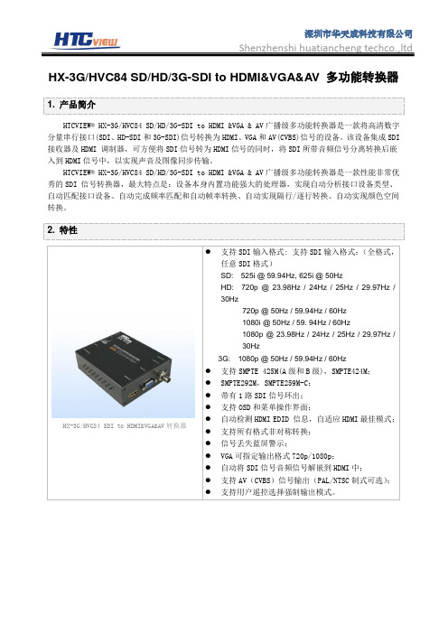
HX-3G/HVC84 SD/HD/3G-SDI to HDMI&VGA&AV 多功能转换器1. 产品简介HTCVIEW® HX-3G/HVC84 SD/HD/3G-SDI to HDMI &VGA & AV广播级多功能转换器是一款将高清数字分量串行接口(SDI、HD-SDI和3G-SDI)信号转换为HDMI、VGA和AV(CVBS)信号的设备。
该设备集成SDI 接收器及HDMI 调制器,可方便将SDI信号转为HDMI信号的同时,将SDI所带音频信号分离转换后嵌入到HDMI信号中,以实现声音及图像同步传输。
HTCVIEW® HX-3G/HVC84 SD/HD/3G-SDI to HDMI &VGA & AV广播级多功能转换器是一款性能非常优秀的SDI 信号转换器,最大特点是:设备本身内置功能强大的处理器,实现自动分析接口设备类型、自动匹配接口设备、自动完成频率匹配和自动帧率转换、自动实现隔行/逐行转换、自动实现颜色空间转换。
2. 特性HX-3G/HVC84 SDI to HDMI&VGA&AV转换器●支持SDI输入格式: 支持SDI输入格式:(全格式,任意SDI格式)SD: 525i @ 59.94Hz, 625i @ 50HzHD: 720p @ 23.98Hz / 24Hz / 25Hz / 29.97Hz / 30Hz720p @ 50Hz / 59.94Hz / 60Hz1080i @ 50Hz / 59. 94Hz / 60Hz1080p @ 23.98Hz / 24Hz / 25Hz / 29.97Hz /30Hz3G: 1080p @ 50Hz / 59.94Hz / 60Hz●支持SMPTE 425M(A级和B级),SMPTE424M;●SMPTE292M,SMPTE259M-C;●带有1路SDI信号环出;●支持OSD和菜单操作界面;●自动检测HDMI EDID 信息,自适应HDMI最佳模式;●支持所有格式非对称转换;●信号丢失蓝屏警示;●VGA可指定输出格式720p/1080p;●自动将SDI信号音频信号解嵌到HDMI中;●支持AV(CVBS)信号输出(PAL/NTSC制式可选);●支持用户遥控选择强制输出模式。
SDI使用说明范文
SDI使用说明范文SDI(Serial Digital Interface)是一种数字传输接口标准,常用于将数字视频信号从一设备发送到另一设备,如从摄像机到监视器、从播放器到电视等。
本文将详细介绍SDI的使用说明,并提供相关技术细节,以帮助读者更好地理解和应用SDI接口。
1.SDI接口概述SDI接口是一种串行数字接口,采用同轴电缆传输数字信号。
它不仅可以传输视频信号,还可以传输音频和其他数据。
SDI接口有多种版本,包括SD-SDI、HD-SDI和3G-SDI,每个版本都有不同的最大传输速率和支持的分辨率。
2.SDI接口特点SDI接口具有以下特点:(1)高质量传输:SDI接口传输的是数字信号,不会因传输距离或信号质量变化而产生丢失或模糊等问题,保证了高质量的视频和音频传输。
(2)长距离传输:SDI接口可以在可接受的传输距离范围内传输信号,通常可以达到几百米甚至上千米。
(3)稳定性强:SDI接口在传输过程中稳定性较高,对于其他设备的电磁干扰和噪声具有较强的免疫能力。
(4)插拔方便:SDI接口采用BNC连接器,插拔方便,接触可靠。
3.SDI接口应用场景SDI接口被广泛应用于专业广播、制作和视频监控等领域。
以下是一些常见的SDI接口应用场景:(1)电视广播:SDI接口可用于将摄像机拍摄的画面传输到广播台,同时也可用于将广播信号传输到电视台进行播放。
(2)视频监控:SDI接口可用于将监控摄像机拍摄的画面传输到监视器,以便实时观察监控区域。
(4)医疗影像:SDI接口可用于将医疗设备拍摄的影像传输到显示器,以便医生进行诊断和分析。
(5)演出现场:SDI接口可用于将舞台上的视频画面传输到大屏幕上,以便观众观看。
4.SDI接口连接方法SDI接口连接通常使用BNC连接器,下面介绍几种常见的连接方法:(1)点对点连接:将一端的SDI输出端口与另一端的SDI输入端口连接,用于将视频信号从一设备传输到另一设备。
(2)多路复用器连接:多个SDI信号可以通过多路复用器合并为一个信号,然后通过一个SDI输出端口传输到另一设备。
SDI光端机 (高清SMPTE-424M标准)

产品特色✧一路HD-SDI高清数字视频及音频信号的光纤传输✧通过Pathological(极度恶劣环境)测试✧SD, HD, 3G 输入自动检测,支持270Mbit/s - 1.48Gbit/s -3Gbit/s 速率;支持新的1080P 3Gbps HD-SDI格式✧支持SMPTE-424M 3Gbps HD-SDI、SMPTE-292MHD-SDI 、SMPTE-259M SDI串行数字视频信号及DVB-ASI信号✧通过多模或单模光纤进行可靠的传输,单模光纤10KM以上,最远可达80KM✧光口使用SFP光纤模块不需断电即可更换,可根据实际传输距离灵活选用光纤模块(高清SDI光端机专用VIDIO SFP光模块)✧面板接口提供数字HD-SDI视频(BNC接口)和LC光纤接口✧带一路RS485反向控制数据简述该SDI系列光端机是一个迷你型的3Gbps HD-SDI数字视频光纤传输系统,支持新的1080P 3Gbps HD-SDI格式,可以在单模或多模光纤上长距离、无失真的传输一路符合SMPTE-424M 3Gbps HD-SDI,SMPTE-292M HD-SDI 或SMPTE-259M SDI串行数字视频信号及DVB-ASI信号。
由于采用了先进的数字光纤传输技术,在Mini-3GHD系统中用户可不作任何调整,设计简易,工作安全可靠。
SD/HD/3G SDI光端机产品最早为广电行业客户开发使用,应用于电视台演播厅,大运会直播现场,后来延伸至1080P高清监控领域,可带反向控制数据;速率是1.485G(也称1.5G,对应SMPTE-292M标准,支持720P)和2.97G (也称3G,对应SMPTE-424M标准,支持FULL HD全高清1080P)。
目前市面上号称能做SDI光端机的厂商很多,但是绝大部分产品不能通过SDI病态码测试,传输规格码率信号的时候勉强可用,但是传输不规则码率信号的时候问题立即体现,在1.5G速率下(720P或1080i应用)出现问题的概率低一些,在3G速率下(1080P应用)出现问题的概率高,主要表现为高清视频传输过程中时而出现闪屏、黑屏、蓝屏,不能保证画面连续流畅播放,导致这些问题的原因主要有二:其一,采用的高清SDI光端机方案不成熟或者设计缺陷,这个原因占小部分;其二,成本因素,市面上大部分的SDI光端机采用普通SFP光模块,即用1.25G速率和2.5G速率的数字SFP光模块来代替SDI光端机专用VIDIO SFP 光模块,这样不可避免传输码率不规则的时候出现大量误码。
星科(StarTech)SDI2HD 3G SDI到HDMI转换器商品说明说明书
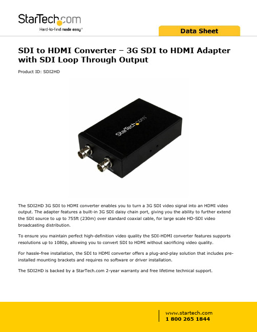
SDI to HDMI Converter – 3G SDI to HDMI Adapter with SDI Loop Through OutputProduct ID: SDI2HDThe SDI2HD 3G SDI to HDMI converter enables you to turn a 3G SDI video signal into an HDMI video output. The adapter features a built-in 3G SDI daisy chain port, giving you the ability to further extend the SDI source to up to 755ft (230m) over standard coaxial cable, for large scale HD-SDI video broadcasting distribution.To ensure you maintain perfect high-definition video quality the SDI-HDMI converter features supports resolutions up to 1080p, allowing you to convert SDI to HDMI without sacrificing video quality.For hassle-free installation, the SDI to HDMI converter offers a plug-and-play solution that includes pre-installed mounting brackets and requires no software or driver installation.The SDI2HD is backed by a 2-year warranty and free lifetime technical support.Certifications, Reports and Compatibility Applications•Convert a 3G SDI video run to HDMI from up to 755ft (300m) away•Connect your HDMI display to a 3G SDI video run•Output to an HDMI Display and continue your 3G SDI run up to an additonal 755ft (300m) using the daisy chain portFeatures•Built-in 3G SDI daisy chain port•Receives 3G SDI signals from up to 755ft (230m)•Supports video resolutions up to 1920x1200 / 1080p•Plug and play SDI to HDMI conversion•Supports AES & EBU Audio Decoding•Pre-installed Mounting bracketsWarranty 2 YearsHardware Active or Passive Adapter ActiveAudio YesAV Input SDI (BNC)AV Output HDMISDI (BNC)Cabling CoaxialChipset ID Gennum - GV7600Daisy-Chain YesPorts1Rack-Mountable YesPerformance Audio Specifications8 Channel Digital Audio @ 48 kHzMax Distance230 m / 755 ftMaximum Cable Length754.4 ft [230 m]Maximum Data Transfer Rate 2.97 GbpsMaximum Digital Resolutions1080pSupported Resolutions1920x1080 (1080p) @ 24, 25, 30, 50 & 60 FPS1920x1080 (1080i) @ 50 & 60 FPS1280x720 (720p) @ 24, 25, 30, 50 & 60 FPSSupports 525i & 625i SD D1 formatSupports 8-bit or 10-bit component digital video RGB or YCbCr 4:4:4 sampled YCbCr 4:2:2 or 4:2:0 sampledWide Screen Supported YesConnector(s)Connector A 1 - SDI (BNC) Receptacle InputConnector B 1 - HDMI (19 pin) Female OutputConnector Type(s) 1 - SDI (BNC) Receptacle Output Power Center Tip Polarity PositiveInput Current0.5 AInput Voltage100 - 240 ACOutput Current 2 AOutput Voltage 5 DCPlug Type MPower Consumption (In Watts)10Power Source AC Adapter IncludedEnvironmental Humidity5% to 90 % RH (no condensation)Operating Temperature0°C to 70°C (32°F to 158°F)Storage Temperature-10°C to 80°C (14°F to 176°F)Color BlackPhysicalCharacteristicsProduct Height 1 in [2.5 cm]Product Length 3.9 in [10 cm]Product Width 2.8 in [70 mm]Weight of Product7.3 oz [207 g]PackagingPackage Height 2 in [52 mm]InformationPackage Length 6 in [15.2 cm]Package Width8.5 in [21.5 cm]Shipping (Package) Weight17.4 oz [492 g]What's in the Box Included in Package 1 - SDI to HDMI Adapter1 - Mounting bracket assembly (attached)1 - Universal Power Adapter (NA/UK/EU/)1 - Instruction manualProduct appearance and specifications are subject to change without notice.。
ProHD-4601 HDMI to SDI 转换器使用说明书
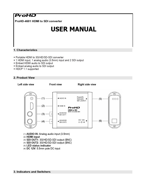
ProHD-4601 HDMI to SDI converter1. Characteristics◆Portable HDMI to 3G/HD/SD-SDI converter◆1 HDMI input, 1 analog audio (3.5mm) input and2 SDI output◆Embed HDMI audio to SDI output◆Embed analog audio to SDI output◆HDCP 1.1 supported2. Product ViewLeft side view Front view Right side view⑴AUDIO IN: Analog audio input (3.5mm)⑵HDMI input⑶SDI OUT1: 3G/HD/SD-SDI output (BNC)⑷SDI OUT2: 3G/HD/SD-SDI output (BNC)⑸LED status indicator⑹DC 12V: 5.5mm pole DC input3. Indicators and SwitchersPower (Red): Power indicator⑴ Status (Green): Status indictor, lights on when there’s HDMI input recognized⑵ SDI LOCK (Yellow): SDI indicator, lights on when there’s SDI output⑶4. Specifications5. Maintenance1. Please do not disassemble the product by yourself.2. Keep the product away from rain or moisture.3. Please use the provided power adapter and if you use third party power adapter, please make sure thevoltage range, supplied power, and polarity of power lead are fit.This model is manufactured, warranted and supported by SWIT Electronics Co., Ltd. / SWIT Electronics USA, LLC , and distributed in North America by JVC Professional Video Products .To obtain service or for further information, please contact:SWIT Electronics USA, LLC.Address: 4300 Stevens Creek Blvd., Suite 230, San Jose, CA 95129Toll free: 1 866 986-SWIT (7948) • Tel: 408 260-8258·Fax: 408 228-8438Email: ************ • Website: 。
sdi与hdmi

sdi与hdmi目前主流的高清视频接口中,当数SDI和HDMI接口,其普及速度非常快,尤其是在高清视频摄像机、高清播放机以及高清显示设备中,已经开始广泛带有。
SDI其英文全称是“Serial Digital Interface ”,中文名称是串行数字接口。
串行接口是把数据字的各个比特以及相应的数据通过单一通道顺序传送的接口。
由于串行数字信号的数据率很高,在传送前必须经过处理。
用扰码的不归零倒置(NRZI)来代替早期的分组编码,其标准为SMPTE-259M和EBU-Tech-3267,标准包括了含数字音频在内的数字复合和数字分量信号。
SDI是专业的视频传输接口,一般用于广播级视频设备中。
SDI和HDMI这两个接口都支持无压缩数字视频传输,但HDMI接口要用19根线了传输,SDI用普通的75欧姆同轴线就可以。
HDMI目前最长只能传输40米,SDI可以传输120-400米。
HDMI其英文全称是High Definition Multimedia,中文解释就是高清晰度多媒体接口,支持HDCP,主要用于消费类电子产品上。
HDMI是首个支持在单线缆上传输,不经过压缩的全数字高清晰度、多声道音频和智能格式与控制命令数据的数字接口。
HDMI接口由Silicon Image美国晶像公司倡导,联合索尼、日立、松下、飞利浦、汤姆逊、东芝等八家著名的消费类电子制造商联合成立的工作组共同开发的。
HDMI最早的接口规范HDMI1.0于2002年12月公布,目前的最高版本是于今年6月发布的HDMI1.3规范。
作为HDMI接口可以提供高达5Gbps的数据传输带宽,可以传送无压缩的音频信号及高分辨率视频信号,同时无需在信号传送前进行数/模或者模/数转换,可以保证最高质量的影音信号传送。
与DVI相比,HDMI可以看成是DVI接口的强化与延伸,HDMI在传输数字视频信号的同时还可以传输数字音频信号(即音频/视频采用同一电缆),并增加了对HDCP的支持,同时提供了更好的DDC可选功能。
