GM650TestTool使用说明
DTG650用户手册说明书
V E R S A T I L I TY// DgT 650USER MANUAL//. . . . . . . . . . . . . . . . . . . . . . . . . . . . . . . . . . . . . . . . . . . . . . . . . . . . . . . . . . . . . . . . . . . . . . . . . . . . . . . . . . . . . . . . . . . . . . . . . . . . . . . . . . . . . . . . . . . . . . . . . . . . . . . . . . . . . . . . . . . . . . . . . . . . . . . . . . . . . . . . . . . . . . . . . . . . . . . . . . . . . . .. . . . . . . . . . . . . . . . . . . . . . . . . . . . . . . . . . . . . . . . . . . . . . . . . . . . . . . . . . . . . . . . . . . . . . . . . . . . . .. . . . . . . . . . . . . . . . . . . . . . . . . . . . . . . . . . . . . . . . . . . . . . . . . . . . . . . . . . . . . . . . . . . . . . . . . . . . . . . . . . . . . . . . .. . . . . . . . . . . . . . . . . . . . . . . . . . . . . . . . . . . . . . . . . . . . . . . . . . . . . . . . . . . . . . . . . . . . . . . . . . . . . . . . .. . . . . . . . . . . . . . . . . . . . . . . . . . . . . . . . . . . . . . . . . . . . . . . . . . . . . . . . . . . . . . . . . . . .. . . . . . . . . . . . . . . . . . . . . . . . . . . . . . . . . . . . . . . . . . . . . . . . . . . . . . . . . . . . . . . . . . . . . . . . . . . . . . . . . . . .. . . . . . . . . . . . . . . . . . . . . . . . . . . . . . . . . . . . . . . . . . . . . . . . . . . . . . . . . . . . . . . . . . . . . . . . . . . . .. . . . . . . . . . . . . . . . . . . . . . . . . . . . . . . . . . . . . . . . . . . . . . . . . . . . . . . . . . . . . . . . . . . . . . . . . . . . . . . . . . . . .. . . . . . . . . . . . . . . . . . . . . . . . . . . . . . . . . . . . . . . . . . . . . . . . . . . . . . . . . . . . . . . . . . . . . . .// IntroThank you for choosing a LEWITT DGT 650!In brief: It’s the most versatile USB microphone on the market. It’s compatible with Windows, Mac and even iOS devices. It can be used to record vocals, instruments, ambient sound, samples, podcasts and more, both mono with a cardioid polar pattern and stereo thanks to its XY capsule arrangement.Plug in and record your guitar, synthesizer, mixing desk or any other line output-equipped device via the brea-kout box. You can even plug any MIDI input device directly into your DGT 650’s own 5-pin MIDI jack ...You see, this is way more than a simple USB microphone: it’s your Digital Multi-T ool.// Features//XY stereo capsule arrangement for authentic recordings of any acoustic event// Switchable to cardioid polar pattern// Hi-Z stereo line-in (6.3 mm, ¼ inch) for directly connecting your instruments// Illuminated user interface for quick and easy handling even in dark environments//Streamlined cable handling due to our breakout box // Recording on the go with iPhone, iPod touch or iPad // Built in lithium-ion battery for mobile applications// Bus-powered on PC & Mac// 4 recording modes// MIDI support// Headphone amp// Zero-latency direct monitoring// Mixable direct monitoring and tape return signal for host device playback and zero-latency monitoring of the microphone// Asynchronus USB transfer: precise internal clock handles the samplerate timing to avoid jitter and ensure bit & pitch accurate audio reproduction // T op applications // Home studio and live recording// Mobile / outdoor recording// Sample and demo recording// Podcasts and YouTube productions// Recording ModesWe’ve built four different recording modes into your DGT 650 to make it the most versatile USB microphone in the world, serving you as a true digital multi-tool. Since we’ll need to refer to those different modes later on in this user manual (and because we think they’re really cool), we’d like to briefly introduce them to you here:XY Stereo Mode // Two cardioid capsules with 90° opening for XY stereo recording. Use this mode for recor-ding live concerts, band rehearsals, ambient sounds, background vocals and for similar applications where you want to capture the room sound and the stereo image of any acoustic event.Cardioid Mode // The two capsules are mixed together to create a cardioid pattern. Best used for vocal recor-ding or other applications where you need good rear and side rejection.Singer/Songwriter Mode // Channel 1 is the cardioid mic and channel 2 is the line input. Use this mode for simultaneous recording of acoustic and line sources. For example: plug in your guitar to the line input and sing into the microphone to put the two signals on separate tracks. If you plug a stereo source into the line input, it will be summed mono (this could possibly cause phase issues on some synthesizers).Stereo Line-In Mode // Used to capture a stereo line signal. Connect a synthesizer or mixing console output and record it directly to your device.// SetupConnect the breakout box to the lockable hi-speed 18-pin data connector (11) of the microphone, then connect the USB cable to the computer or the lightning connector (sold separately) to your iOS device. If you need to extend the USB cable, be sure to use a HI-SPEED-compatible USB extension cord. We do not recommend the use of USB hubs, but if you need to, only use a powered hub or use the dedicated charging port to power the DGT 650.OS X (10 .6 and up) //Connect the DGT 650 to the breakout box and the breakout box to the USB port.Open “system preferences” in the menu at the top of the screen.Click on the “Sound” icon.Click the “Output” tab and select “DGT 650.”Click the “Input” tab and also select the “DGT 650.”windows //Connect the DGT 650 to the breakout box and the breakout box to the USB port.Download and install the drivers – please follow the onscreen instructions.T o use the DGT 650 with your preferred sequencer / digital audio workstation, refer to the software manual. Download the Control Center at www .lewitt-audio .com/DgT-Series/DgT-650/Downloads in order to change the settings of your DGT 650 from your computeriOS //Just plug and play. But do make sure that the internal battery is charged or that a charger is connected to the dedicated charging port.//User Interface// Displays active recording mode b // Cardioid Modec // Singer/Songwriter Moded //Stereo Line-In Mode// Mix the output signal of your device playback and your voice at the same time ...Return // Monitor the output of your PC, Mac or iOS device Direct //Monitor the input of the DGT 650 without any latency // Use these filters to get rid of unwanted The high-pass filters at 80Hz or 160Hz affect the microphoneand line input at 12dB per octave.Pre-Attenuation // For loud signals to prevent clipping. a b c d//Displays a value for some settings//Input and output gain settingsBattery Status // Indicates whether the device isJog Dial //Push and turn to change settings.Status Indicator //Displays the current state of Illuminated white // Standard modeNot illuminated // Settings modeIlluminated red // Overload has occurred. Decrease the gain or change the pre-attenuationsetting.Micro USB port; use a dedicatedmobile devices to charge the internal battery. It is notpossible to charge the microphone by connectingthe dedicated charging port to a PC’s USB port, butthere’s no need to do so, since the DGT 650 will thenbe charged via the data connection.//Connects your DGT 650 with//Connects your DGT 650 tobattery will be charged.//Plug in your headphones//Plug in your MIDI device here.//Plug in your instrument here.// Operating the microphoneThe following will walk you through all the settings of your DGT 650.Standard Mode //Settings Mode// This is where you can change all the settings on your DGT 650 including recording modes,rotate it to change the selected setting.headphone/Output gain// The headphone symbol is lit. Rotate the jog dial to change the output volume. ATTENTION: Your DGT 650 has a professional, built-in headphone amp. Be sure to check your gain settings befor using headphones, the signal can be very loud. Honestly, we mean it - this can seriously harm your ears. Input gain // Press the jog dial until the input gain symbol is lit. We use a very fine gain control – there are intermediate steps that do not show up on the LEDs. The settings will change depending on the selected recording mode. You can set input gain levels for all 4 recording modes individually.Stereo Mode selected // Gain L R will be lit. Rotate the jog dial to change the gain for both capsules together.Cardioid Mode selected// Gain L R will be lit. Rotate the jog dial to change the gain.Singer/Songwriter Mode selected// Gain L will be lit first. This lets you set the gain for the left channel – in this mode, it’s the cardioid microphone. Press the jog dial; Gain R will now be lit. This lets you change the gain of the right channel – in this mode, it’s the line input.Stereo Line Mode selected// Gain L R will be lit first. This lets you change the left and right-channel gain settings together. Press the jog dial again; Gain L will be lit. This lets you adjust the gain of the left input separately. Press the jog dial again to change the gain of the right channel separately.Recording Mode // The selected recording mode symbol is lit. Rotate the jog dial to change the recording mode. Press the jog dial to switch to the next setting.//high-pass Filter //160Hz@12dB/Oct.Pre-Attenuation //by rotating the jog dial the options are 0dB, -10dB and -20dB.// T ech Data// MicrophoneAcoustical operating principle //pressure gradient transducer, permanently polarized, XY-stereoTransducer Ø //2 x 17 mm / 0.67 inchPolar pattern //cardioid, XY-stereoFrequency range //20 ... 20,000 HzDynamic range of mic. Amp. //110 dB-APre-attenuation pad //10 dB20 dB switchableBass cut filter slope //12 dB / octave at 80 Hz12 dB / octave at 160 Hz // generalResolution //24 BitSample rates //44.1 kHz // 48 kHz // 96 kHzRecording modes //1: left / right = microphone X/Y2: left / right = microphone cardioid3: left / right = stereo line-in4: left = microphone cardioid / right = line input leftMaster gain (analogue) //0 dB ... 40 dBSupply voltage //USB high-power device, 5V (+/-5%) / Internal battery Internal battery //Li-ion, 950mAh / 3,7V; > 3h playtimeCurrent consumption //< 500mA (charging) // < 275mA (normal operation) Connector //18-pin lockable hi-speed connectorDimensions //138 x 52 x 36 mm, 5.43 x 2.04 x 1.42 inch Net weight //310 g, 10.9 oz// Sensitivity, SPL, Self-noise0 dB gain, no attenuators // Sensitivity: -45.6 dBFSLimiting spl: 140 dBSelf-noise: 31.6 dB, 29.2 dB (A)10 dB gain, no attenuators // Sensitivity: -35.6 dBFSLimiting spl: 130 dBSelf-noise: 25 dB, 21 dB (A)20 dB gain, no attenuators // Sensitivity: -25.6 dBFSLimiting spl: 120 dBSelf-noise: 24.9 dB, 19.6 dB (A)30 dB gain, no attenuators // Sensitivity: -15.6 dBFSLimiting spl: 110 dBSelf-noise: 26.7 dB, 20.8 dB (A)40 dB gain, no attenuators // Sensitivity: -5.6 dBFSLimiting spl: 100 dBSelf-noise: 22.5 dB, 18 dB (A)// Line-inInput impedance //> 1 Meg ohmFull scale input voltage //8 dBuInput dynamic range //110 dB (A)Frequency response //20 ... 20,000 Hz// headphonesOutput power //40mW / 16 ohm THD+N < 0.2 %20mW / 32 ohm THD+N < 0.14 % Frequency response // 30 ... 20,000 Hz Headphone volume control // - 60 dB ... 0 dB// Saftey guidelines// The capsule is a sensitive, high precision component. Make sure you do not drop it from high heights and avoid strong mechanical stress and force.// T o ensure high sensitivity and best sound reproduction of the microphone, avoid exposing it to moisture, dust or extreme temperatures.// Keep this product out of the reach of children.// Do not use force on the switch or cable of the microphone.// When disconnecting the microphone cable, grasp the connector and do not pull the cable.// Do not attempt to modify or fix it. Contact qualified service personnel in case any service is needed. Please do not disassemble or modify the microphone for any reasons as this will void users warranty.// The casing of the microphone can be cleaned easily using a wet cloth, never use alcohol or another solvent for cleaning. If necessary the foam wind stopper can be washed with soap water. Please wait till it is dry before using it again.// Please also refer to the owner’s manual of the component to be connected to the microphone.// warrantyAll products manufactured by LEWITT GmbH feature a limited two-year warranty. This two-year warranty is specific to the date of purchase as shown on your purchase receipt.LEWITT GmbH shall satisfy the warranty obligations by remedying any material or manufacturing faults free of charge at LEWITT’s discretion either by repair or by exchanging individual parts or the entire appliance. Any defective parts removed from a product during the course of a warranty claim shall become the property of LEWITT GmbH.While under warranty period, defective products may be returned to the authorized LEWITT dealer together with original proof of purchase. T o avoid any damages in transit, please use the original packaging if available. Please do not send your product to LEWITT GmbH directly as it will not be serviced. Freight charges have to be covered by the owner of the product.For further information please visit or check your warranty card.// Regulatory Information LEWITT GmbH declares under its sole responsibility that DGT 650 complies with the European directive 2004/108/EC and 2006/95/EC. The product has been tested according to harmonized European standards: EN 55022: 2010EN 55024: 2010EN 61000-3-2: 2006 + A2: 2009EN 61000-3-3: 2008EN 60950-1:2006 + A11:2009 + A1:2010 + A12:2011Product testing was carried out by SEM. T est Compliance Service Co., Ltd. notified body number SEM11124587 / SEM11126875.LEWITT GmbH hereby declares under its sole responsibility that DGT 650 has been tested and conforms to the following FCC and ANSI standards: FCC Part 15B Section 15.205, 15.107 and 15.109 ANSI C63.4-2009Product testing was carried out by SEM. T est Compliance Service Co., Ltd.WEEE note: Electronic waste has to be collected separately. Please bring this device to a local recycling center at the end of its life time.Manufacturers signature:Date: 9th October 2014 DI Roman Perschon Place: Vienna, AUSTRIA CEO – Lewitt GmbHDeclaration of conformity can be downloaded at www .lewitt-audio .com or obtained from*********************.。
TestTools使用说明书
TestToolsV5.0帮助文档光猫测试维护工具说明书mervyn2014-3-29目录一、TestToolsV5.0程序概述: (2)二、TestToolsV5.0程序的运行及配置步骤: (2)三、TestToolsV5.0功能模块介绍: (4)(一)TestToolsV5.0初始化配置: (4)(二)设备登陆信息配置: (5)(三)更新IP地址及重置IP地址功能: (6)(四)设备配置管理功能: (7)4.1查看Telecomadmin密码 (7)4.2查询地区码: (7)4.3查询设备软件版本 (8)4.4查询设备硬件版本 (8)4.5重置telecomadmin密码: (8)4.6修改超级用户名: (9)4.7修改地区码: (10)4.8初始化F460C220配置 (12)4.9软重置设备 (12)4.10打开Web配置及打开Web_shell_cmd配置 (12)(五)设备MAC地址管理 (12)5.1 清空MAC地址(请慎用) (12)5.2 MAC地址管理 (13)5.3 点亮及熄灭所有的灯 (13)(六)光猫设备端口管理 (14)6.1 Telnet端口管理 (14)6.2 批量尝试开启Telnet端口 (14)6.3自定义尝试批量开启Telnet端口 (15)6.4关闭Telnet23端口 (15)6.4关闭80端口 (15)(七)光猫文件配置 (15)7.1 添加、建立、删除web_shell_cmd.gch文件 (15)(八)测试数据核对 (16)8.1 ECC上传数据核对 (16)8.2 生成测试报表 (18)8.3 备份数据库 (19)(九)帮助 (20)9.1 技术支持 (20)9.2意见反馈 (21)9.3关于TestTools (21)四、程序使用声明 (22)一、TestToolsV5.0程序概述:TestTools V5.0程序的主要功能是集成了对光猫的测试所使用到的一些测试脚本功能,并加入了连通测试的功能,测试序列号比对及生成测试文档的功能,可以在测试的过程中查询某个串号是否已经上传到服务器等功能,方便测试工作的开展。
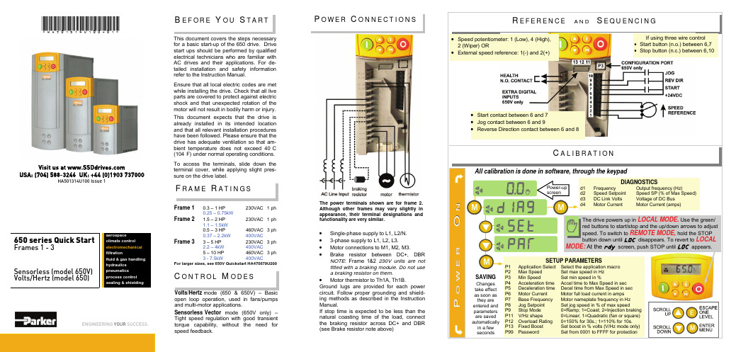
650驱动器基本启动指南说明书
B E F O R E Y O U S TA R TThis document covers the steps necessary for a basic start-up of the 650 drive. Drive start ups should be performed by qualified electrical technicians who are familiar with AC drives and their applications. For de-tailed installation and safety information refer to the Instruction Manual.Ensure that all local electric codes are met while installing the drive. Check that all live parts are covered to protect against electric shock and that unexpected rotation of the motor will not result in bodily harm or injury. This document expects that the drive is already installed in its intended location and that all relevant installation procedures have been followed. Please ensure that the drive has adequate ventilation so that am-bient temperature does not exceed 40°C (104°F) under normal operating conditions.To access the terminals, slide down the terminal cover, while applying slight pres-sure on the drive label.•Single-phase supply to L1, L2/N. •3-phase supply to L1, L2, L3.•Motor connections to M1, M2, M3.•Brake resistor between DC+, DBR NOTE : Frame 1&2 230V units are not fitted with a braking module. Do not use a braking resistor on them .•Motor thermistor to Th1A, Th1B.Ground lugs are provided for each power circuit. Follow proper grounding and shield-ing methods as described in the Instruction Manual.If stop time is expected to be less than the natural coasting time of the load, connect the braking resistor across DC+ and DBR (see Brake resistor note above)The power terminals shown are for frame 2. Although other frames may vary slightly in appearance, their terminal designations and functionality are very similar.Frame 1 0.3 – 1 HP 230VAC 1 ph0.25 – 0.75kWFrame 2 1.5 – 2 HP 230VAC 1 ph 1.1 – 1.5kW0.5 – 3 HP 460VAC 3 ph 0.37 – 2.2kW 400VACFrame 3 3 – 5 HP 230VAC 3 ph 2.2 – 4kW 400VAC5 – 10 HP 460VAC 3 ph 3 - 7.5kW 400VACFor larger sizes, see 650V Quickstart HA470679U200P OW E R C O N N E C T I O N S*HA501314U100-01*650 series Quick StartFrames 1 - 3Sensorless (model 650V) Volts/Hertz (model 650)ENGINEERING YOUR SUCCESS.aerospaceclimate control electromechanical filtrationfluid & gas handling hydraulics pneumatics process control sealing & shieldingVolts/Hertz mode (650 & 650V) – Basic open loop operation, used in fans/pumps and multi-motor applications.Sensorless Vector mode (650V only) – Tight speed regulation with good transient torque capability, without the need for speed feedback.C O N T R O L M ODE SF R A M E R AT I NG SAll calibration is done in software, through the keypadC A L I B R AT I O NIf using three wire control •Start button (n.o.) between 6,7 •Stop button (n.c.) between 6,10Speed potentiometer: 1 (Low), 4 (High),External speed reference: 1(-) and 2(+)Start contact between 6 and 7 Jog contact between 6 and 9Reverse Direction contact between 6 and 8Visit us at USA: (704) 588-3246 UK: +44 (0)1903 737000HA501314U100 Issue 1S E R I A L C O M M SC LO N I N G650 and 650V drives may be cloned using the 6514 Clone option that plugs into the keypad slot. Settings include to/from, I/O configuration and full/part transfer.The 650 has additional features which can beaccessed via the drive menu, or for the 650V using DSE Lite. Refer to the product manual for details. Flycatching - When enabled, lets the drive start into a spinning load by doing a frequency search. Skip Frequencies – Two selectable avoidance frequencies and associated window for each. PID – Provides closed loop process control S-Ramp – When enabled, introduces a second order slope to the ramp for smoother transitions. Configurable Outputs – The digital outputs on the 650 can be configured to pick one of 6 parameters. The outputs on the 650V are totally configurable. Auto Restart - After a fault, the drive attempts a number of restarts after a settable delay.Custom Screens - Allows the use of a Custom parameter to be displayed. (650V only)Encoder – Terminals 12 &13 (650V only) can be used for a quadrature (not complementary) encoder input for steady-state speed feedback.Associated Literature650 Installation Manual HA464828Uxxx 650 Software Manual HA467872Uxxx 650V Installation Manual HA467649Uxxx 650V Software Manual HA501306UxxxThe 6513 Serial Communication option can be plugged into the keypad slot. It can be used to exchange information between the Master and Slave drives in RS485/232 format, up to 32 units can be connected together. Front panel LED indicators provide status and health indication.A DVA N C E D F E AT U R E S。
GM6600操作说明

GM6600操作说明
一:首先打开电源开关,确认所有控制部分都得电。
二:在测试之前,首先需要原点归零,在空载时,需把现在测试读值归零。
三:在触摸屏上可以设置速度,位移。
四:怎么实现自动测试
如果要进行测试,需把气压棒安装好,此时只需按下触摸上的“START”按扭,测试机就开始测试,等钢丝绳的位移等于8inches时,电脑开始读值,以后每隔2inches, 电脑自动会把值读出并自动填入触摸屏的表格中。
如果要进行下一挡的测试,只需重复以上的动作。
所有挡位测试完后,您需要把数据清零,方可进行下一根测试棒的测试。
五:测试条件
1:测试速度:20inches/min
2:测试总位移30inches
3:当钢丝绳的位移等于8inches时,电脑开始读值,以后每隔2inches。
五:怎么实现手动操作
等机台处于停止状态时,您只需按下操作面板上的按
钮,机台就会实现相应的动作。
六:怎么实现打印
等一整页数据测试完后,您只需按下触摸屏上的“PRINT”按钮,就会把此页的内容打印出来。
七:怎么排除故障
如果机台按下任何按钮没有任何反映,此时您需要按下触摸屏的“故障复位”按钮,再按“原点复归”按钮,等机台完全处于停止状态时,您就可以做相应的动作。
IPC-TM-650中文指导手册
IPC-TM-650中文指导手册简介IPC-TM-650是一份关于电子产品测试方法的指导手册。
本手册旨在提供一套标准的测试方法和流程,以确保电子产品的质量和可靠性。
目标本指导手册的目标是为电子产品制造商提供一套简单且没有法律复杂性的测试策略,以确保产品符合相关标准和规范。
内容IPC-TM-650指导手册包含了多个章节,涵盖了各种不同的电子产品测试方法。
以下是一些重要的章节和内容:1. IPC-TM-650测试方法介绍 - 该章节提供了对IPC-TM-650指导手册的概述,介绍了测试方法的分类和应用。
2. 物理性能测试 - 该章节介绍了各种物理性能测试方法,如机械强度测试、耐热性测试、耐寒性测试等。
3. 电气性能测试 - 该章节涵盖了电气性能测试的方法,如绝缘电阻测试、电流和电压测试、功率耗散测试等。
4. 环境适应性测试 - 该章节介绍了环境适应性测试的方法,包括高温高湿测试、低温低压测试、振动和冲击测试等。
5. 可靠性测试 - 该章节提供了一套可靠性测试方法,包括寿命测试、可靠性指标测试、失效分析等。
使用建议为了最大限度地发挥IPC-TM-650指导手册的优势,以下是一些建议:1. 熟悉手册内容 - 在使用IPC-TM-650指导手册之前,首先要对手册的内容进行全面的了解,并熟悉各个测试方法的原理和步骤。
2. 简化测试策略 - 根据产品的特点和需求,制定简单且有效的测试策略,避免不必要的测试步骤和复杂性。
3. 遵循标准和规范 - 在进行测试时,确保遵循相关的标准和规范,以确保测试结果的准确性和可靠性。
4. 记录和分析测试结果 - 对测试结果进行记录和分析,及时发现问题并采取相应的措施进行改进。
结论IPC-TM-650中文指导手册是一份重要的电子产品测试方法指导手册,通过遵循其中的测试方法和流程,可以确保产品的质量和可靠性。
制定简单且没有法律复杂性的测试策略,并遵循相关标准和规范,将有助于提高产品的竞争力和用户满意度。
TestTool使用说明

TestTool使用说明打开程序会看到下面这样的主界面从界面可以看到现阶段软件有3个功能:1.未评分文件拷贝2.Vp测试统计3.未评分文件评测对用户选择的功能不同,界面右边会有不同的功能配置。
下面是对每个功能使用的详细过程。
一.VP测试统计该功能是对前台采集下来的数据进行VMOS评分统计,主要统计联通VMOS各个指标。
用户选择该功能后,右侧的“功能配置”会有下图所示选项:可以看到三个check按钮,分别是“统计一个大的根目录”,“过滤找不到的采样点”,“根据log文件进行统计”1.用户不选择任何check按钮,把“原始文件”中设置为样本avi文件,点击“统计目录”后的按钮会弹出下面对话框点击“添加”按钮,添加需要统计的目录。
该目录的目录结构必须是以以下结构存在:“../一侧测试中保存媒体文件文件夹/每个呼叫对应的文件夹/媒体文件”,我们需要添加的目录应该是”../ 一侧测试中保存媒体文件文件夹/”,可以点击“添加“按钮添加多个这样的目录(多次测试产生),注意,添加的这些目录中必须含有前台测试过程中产生的名为”ScoreFileRecord.ini “的文件,不然程序会提示错误,需要从新添加目录。
如果用户已经确定没有再需要添加的目录,点击“确定“按钮回到主界面;在主界面中点击”VP统计“按钮进行统计工作,在统计过程中程序会统计用户在之前设置的每个目录中的数据。
统计过程中,程序界面如下程序会提示“VP统计进行中“,当统计结束后会弹出提示用户选择保存统计结果的目录,当用户选择目录后,在指定的目录下会生成名为“stat_score.txt “的文件,其中记录了联通巡检VMOS的各个指标,如下图:到此,统计工作完成。
2.如果用户选择“统计一个大的根目录“check按钮,在设置样本文件后,用户只需要点击”统计目录“后的按钮,设置一个含有用户需要统计测试所有目录的大目录进行统计工作,注意目录结构必须是以以下结构存在:1 大目录2测试目录3测试呼叫目录3测试呼叫目录3…..2测试目录3测试呼叫目录3测试呼叫目录3…..2….设置完成以后,点击”VP统计”按钮,之后操作与上面相同。
MTK工具使用说明
万物青科技有限公司生产测试流程及工具使用说明文件名称 生产测试流程及工具使用说明 版本 A1.0 编制 金星 日期 2010年8月18日 审核 日期一.生产测试流程图:按照图示生产流程依次进行。
各测试站测试不良品需送维修站经维修人员分析维修后再返回下载测试站重新测试。
二.生产流程详解2.1 SMTSMT工艺流程依次为:来料检测—贴片(胶板)---极性确认--TOP面丝印焊膏---贴片—回流焊—翻板--Bottom面丝印焊膏---贴片—回流焊—外观检验。
2.2 下载通过下载工具将电子书软件下载到电子书的flash芯片中。
2.3 写S/N电子书在写S/N号之前还需要打印序列号标签并粘贴在手机主板上,每只手机板在板测之前必须写入一个序列号。
序列号一般包括主板型号,生产日期,流水号等信息,同时在后面的测试过程中还用来作为保存测试数据的文件名。
2.4 校准(Calibration)校准手机主板的射频指标以及电性能测试。
MTK_ATEDEMO.EXE 工具校准项分为射频和基带两个部分,射频部分包括AFC 、APC 、Path Loss, 基带部分包括ADC• AFC 自动频率控制• APC 自动功率控制• Path Loss 接受增益控制• ADC 电池电量校准2.5 综测主板综测、测试项目包括GSM、DCS、PCS 的功率、相差、均方根相差、频率误差、开关谱、调制谱、接收机灵敏度。
各项目的标准参照GSM 相关标准。
2.6 功能测试功能测试是进入自动测试工程模式,进行充电,SIM卡读取,LED测试,软件版本,LCD显示,按键,MIC,Speaker,耳机,音乐,sd 卡,蓝牙,FM,WIFI功能测试。
三.测试工具使用说明3.1 下载工具使用说明3.1.1 概述该软件通过计算机USB口与电子书连接,并采用串口数据通讯的方式把电子书软件下载到电子书的flash中,该软件由万物青科技提供。
3.1.2 硬件安装使用USB转串口的下载数据线,其下载速率最大可达到921600bit/s,生产厂商建议使用一拖四的USB Hub加USB数据线;使用USB下载数据线,需要先安装USB驱动程序。
SmartTools血流限制训练器用户手册说明书

USER MANUALMy name is Nick Colosi, and I’m the founder of SmartTools, a company dedicated to developing innovative solutions, specializing in blood flow restriction training and IASTM.Our company is based in Cleveland, Ohio—famous for the Rock & Roll Hall of Fame and definitely not your typical start-up location. But, we started packaging and shipping rightout of my parents’ basement and have grown from there.My background is in sports and medicine, and I wanted to combine those two elements to create products. With my frequent travels, I also spend a lot of time away from home. In those situations, I would often say to myself, “I wish I had this sort of product with me.” And you probably do the exact same thing. So, I aim to design products that add the most value to the customer and can suit multiple lifestyles and needs.However, I believe that it’s not only about knowing what products and solutions people want, but also about knowing how they wantto be treated. That’s why customer service is a major component of what we do at SmartTools. You have questions and want answers, sowe take pride in answering those questions promptly. In fact, all emails are answered before the end of the workday, with no carryover.I designed our SmartCuffs and other SmartTools to be intuitive, safe and so easy to use that anyone can do it without issue. That one-time basement business now has distribution centers in almost 50 countries, showing that if you dream it and believe in it, anything is possible. We’re just getting started and look forward to creating even more innovative products that improve the health and wellbeing of the world.Nick ColosiSTATEMENT FROM OUR FOUNDER2WHAT IS LIMB OCCLUSION PRESSURE?Limb Occlusion Pressure (LOP) is the amount of pressure neededto occlude arterial blood flow. This is the gold standard beingused to quantify the amount of pressure needed per user in BFRresearch. Personalized tourniquet pressure for each individualpatient eliminates the need to account for cuff width, limb size, orblood pressure. BFR requires the reduction of arterial inflow andthe elimination of venous outflow. By establishing a baseline LOP,we can know how much to reduce the pressure by so you are neverexercising at occlusion, which is unsafeHOW OFTEN SHOULD IT BE MEASURED?LOP/”Personalized Pressure” should be measured every 2–4 weeks.It does not need to be measured every session unless directed byyour healthcare professionalRECOMMENDED % OF LOP:FOR THE ARM30%–50% LOPFOR THE LEG50%–80% LOP4PRODUCT WARRANTYSmartCuffs® 4.0 device, cuffs, accessories and other attachments are a Limited One-Year Warranty.The SmartCuffs 4.0 device, cuffs, accessories, and other attachments are warranted by Smart Tools Plus, LLC, an Ohio corporation (“SmartTools”), against manufacturing defects in material and workmanship for a period of one year from the date of purchase from SmartTools. In the event of any such defect occurring during the warranty period, SmartTools will, at its option, (a) correct the defect by repair or by replacement of the applicable part or component that fails as a result of such defect, without charge forparts and labor; or (b) replacethe device with one of thesame or then current design.The foregoing warranties donot cover normal wear andtear or cosmetic damage, andare void if the device and/orthe attachments and otheraccessories (collectively, the“product”) are not used inaccordance with the usermanual, are otherwisemisused or modified in anyway, and/or are repairedor altered by anyone otherthan an authorized servicerepresentative of SmartTools.These warranties expresslyexclude transportation,shipping or insurance costs,or defects, damages, or failureresulting from misuse, abuse,improper or abnormal usage,or neglect.All replaced parts andproducts become theproperty of SmartTools. Newor reconditioned parts andproducts may be used in theperformance of warrantyservice. Repaired or replacedparts and products arewarranted for the remainderof the original warranty periodonly. You will be charged forrepair or replacement of partsand products made after theexpiration of the applicablewarranty period.7BluetoothLED Indicator Power Button Pump Housing812 3Apply cuff with the buttons/LED light facing up with the housing situated on the outside of arm. Push the strap of the cuff through plastic Strap Loop. Apply as tight as possible to the upper arm. The bottom flap of the cuff should slide under the top part of the cuff.Connect the SmartCuffs 4.0 device to the SmartCuffs app via Bluetooth.You are ready to begin to operate the SmartCuffs 4.0 device. *To release air from the cuff in case of emergency, press down on the Emergency Air Release Button (location on page 8).APPLYING THE ARM CUFF92 3Apply cuff with the buttons/LED light facing up with the housing situated on the outside of the leg. Push the strap of the cuff through plastic Strap Loop. Apply as tight as possible to the upper leg (closest to hip). The bottom flap of the cuff should slide under the top part of the cuff.Connect the SmartCuffs 4.0 device to the SmartCuffs app via Bluetooth.You are ready to begin to operate the SmartCuffs 4.0 device.*To release air from the cuff in case of emergency, press down on the Emergency Air Release Button (location on page 8).APPLYING THE LEG CUFF110CHARGING AND OTA PROCEDURESCHARGINGTo charge, simply plug the charging cord into the USB-C port. Within 1 min, the center light will turn solid RED or GREEN. RED means the battery is less 100% and it is charging. GREEN means battery level has reached 100%.FIRMWARE UPDATEPlease note, this is not updating the app software. That is done on your phone. This is updating the actual operating system on the SmartCuffs device. You can update the firmware on the individual devices 1 of 2 ways:Via the app»Follow the onscreen instructions on theapp (yellow box onthe home screen ofthe app will promptyou)»This method can only update one unit attime and can take upto 20 minutes Mesh OTA (over-the-air)»This is the most timeefficient method asit will update thefirmware on all unitsat the same time.»OTA update one unit viathe app. Then plug alldevices into power andwithin 1ft of one another.This is required for meshOTA to work. Note: Youdo not need to anythingother than plug theminto power. The devicewill do all the work.»When two devices areupgrading each othervia flash mesh:»the sender:center LED solidorange - blinkinggreen powerbutton»the receiver:center LED blinkingorange - all buttonLEDs are off»Updates one unit ata time»If doesn’t startupdating one unitwithin 10 seconds, turnthe most updated unitoff and back on it again.»When there is no moredevices to upgrade,center LED goes back toindicate battery charge- RED - charging, GREENcharged11EXERCISE PRESCRIPTIONSTRENGTH AND HYPERTROPHYEstablish the ability to perform 30 repetitionsof an exercise PRIOR to applying occlusion. Thiswill equate to about 20% of your 1RM to start.See Appendix 1 for establishing your 1RMestimate. You do not want to exercise to failure(inability to complete all repetitions).12EXERCISE PRESCRIPTIONAEROBIC CONDITIONINGEstablish your Heart Rate Reserve (HRR)(see Appendix 1).Work on treadmill, rower, bike, stair stepper,etc. at 30% HRR to start and increase intensityby 10% each week. More fit individuals canstart at 45% of HRR will need to increase theintensity by 10% each week (up to 60% HRR).20 minutes maximum cuff inflation isrecommended for safe training.14XXX17XXXsmart tools © 2023 Smart Tools Plus, LLC.All rights reserved.。
测试工具使用说明

测试工具使用说明:1、iometer是对存储子系统的读写性能进行测试的软件,可以显示磁盘系统的最大IO能力、最大带宽、CPU使用率等等。
用户可以通过设置不同的测试参数,有存取类型(如顺序,随机),读写块大小,队列深度等,来模拟实际应用的读写环境进行测试,可以准确有效的反映存储系统的读写性能,为各个存储厂商和服务器厂商广泛采用。
举例具体用法如下:1)打开iometer软件,如下图所示:备注:此时的目标文件系统F(红色斜杠),不能直接测试性能,需要先向文件系统写入一定大小的文件iobsw.tst(建议写入的文件大小大于服务器内存)。
2)每一个worker都要选择目标文件系统F,比如:点击worker1,然后选择目标文件系统F,如下图所示:备注:红色X表示选择了目标文件系统F。
依次每一个worker都要操作。
3)当所有worker选定目标文件系统F后,点击按钮,填写of Outstanding I/Os的数值为32(表示进程数)。
4)点击“Acess Specifications”,选择“New”,然后出现设置读写方式(顺序或是随机),数据块大小设置的界面,如下图所示:5)设置完成后,返回上一页点击“Add”按钮,如下图所示6)点击“Result Display”,将“Update Frequency(senconds)向左移动到1s(表示每一秒更新一次)”,然后点击“”按钮,开始写入文件,如下图所示:7)当你进入文件系统中查看,写入的文件大小大于服务器内存大小之后,可以单击“”按钮,停止数据写入。
8)右键“”按钮,选择“Refresh Target Lists”,然后你就会发现文件系统F前段的斜杠消失,表示文件系统F可以进行性能的测试,如下所示:9)然后按照上述步骤2)的操作,将每一个worker选定文件系统F。
10)如果想测试文件系统写或是读性能,就在“Access Specification”菜单下将刚才创建的“Untitled”进行编辑修改。
IPC-TM-650测试方法规范
IPC-TM-650测试方法规范原创工作组:刚性板测试方法任务组(7-11d)1.0范围本方法使用压敏胶带测定镀层、标记油墨或油漆以及与连接印制板有关的其它材料的附着质量。
2.0适用文件商业产品规格型号(CID)A-A-113压敏胶带3.0试样试生产、检验或生产中印制板,每次鉴定应至少进行三次测试。
4.0器具或材料4.1胶带一卷3M600型宽1/2英寸压敏胶带,或者是除了胶带为透明外,符合(CID)A-A-113规定的1型B级压敏胶带要求的其他胶带。
5.0操作程序5.1测试将一块至少长50mm(2.0英寸)的压敏胶带紧紧贴在测试区域的表面上,排除压敏胶带下的空气。
压贴胶带和揭撕胶带之间的时间应少于1分钟。
与测试区域大致呈垂直(直角),迅速施加拉力,撕起胶带。
每次测试均应使用未使用过的胶带。
5.2鉴定目视检查胶带和测试区域,是否有任何部分被撕掉的痕迹。
5.3报告报告应说明测试中是否有材料被撕掉的痕迹。
第1页共31页6.0注6.1如果镀层突沿断裂(碎屑)并附着在胶带上,这只是突沿断裂的痕迹,而不能证明附着力不合格。
6.2如果测试表面有杂质(油、脂等),则可能影响测试结果。
注:本测试方法规范中所适用的材料是IPC技术委员会自行而定的,只是建议性的,使用与否或适用与否完全自定。
IPC对于这种材料的使用、应用或适用概不负责。
使用人还应完全负责保护自己,避免因侵犯专利权而遭受索赔或承担责任。
本测试方法规范中所提到的设备,仅供使用人参考,并不意味着是IPC所指定的设备。
主题:挠性敷金属介质的弯曲疲劳和延展性测定制定日期:1991年3月修订版本:C原创工作组:不适用1范围本测试方法用于测定敷金属层在给定弯曲半径条件下的弯曲疲劳寿命、弯曲疲劳特性和拉伸断裂后的延展变形百分数。
注:当铜箔试样的几何形状和尺寸使得拉伸和断裂测试不适合延展度测定时,可以使用疲劳测试的方法间接测定铜箔的延展度。
注:测试处理可能改变金属导线原有的机械特性。
Transcend MP650 说明书

MP650 使用手册目录产品介绍︱ (5)包装内容︱ (5)产品特色︱ (5)系统需求︱ (6)安全注意事项︱ (6)一般使用 (6)资料备份 (6)注意:过大音量可能造成听力受损 (6)提醒您 (7)MP650概观︱ (8)音乐播放屏幕︱ (9)基本操作︱ (10)充电 (10)开启电源 (10)关机 (10)播放 (11)暂停 (11)下一首 (11)上一首 (11)快转 (11)倒转 (11)增加音量 (11)降低音量 (11)主菜单 (11)录音 (11)A-B 循环播放 (11)锁定 (12)重置 (12)音乐模式︱ (13)播放 MP3、WMA 以及 WMA-DRM10 音乐 (13)档案浏览 (13)播放清单 (13)在播放清单中添加歌曲 (14)从播放清单中删除歌曲 (14)删除档案 (15)收音机模式︱ (15)储存电台频道 (16)快速选择已储存的频道 (16)广播录音 (16)录音模式︱ (17)使用内建麦克风录音 (17)播放声音或 FM 广播录音 (17)档案浏览 (17)删除录音档 (18)设定︱ (19)设定菜单 (19)音场 (EQ) 模式 (19)使用者自订音场 (19)循环模式 (20)播放速度 (20)录音设定 (21)录音质量 (21)VAD (自动音源侦测) (21)对比 (22)屏幕保护 (22)词曲同步 (23)睡眠模式 (23)日期时间设定 (23)设定日期 / 时间 (23)时区 (24)日光节约时间(Daylight Saving Time) (24)重设 FM 预设频道 (25)语言 (25)媒体传输模式 (MTP) (25)播放器信息 (26)安装驱动程序︱ (27)将 MP650 连接到计算机︱ (28)将档案传输至 MP650 (28)安全移除 MP650 (29)Transcend Digital Music Player Utility (30)安装MP650 软件 (30)计算机锁 (32)忘记密码 (37)疑难排解︱ (38)产品规格︱ (40)订购信息︱ (40)质保条款︱ (41)产品介绍︱感谢您购买创见 MP650 MP3 音乐播放器。
罗技m650说明书
将鼠标连接到您的设备您可以使用Bluetooth® Low Energy 连接或我们新的Logi Bolt 接收器将鼠标与您的设备配对。
通过蓝牙®配对:步骤 1从鼠标上取下拉片。
它会自动开启。
通道 1 将准备好配对。
通过Logi Bolt 接收器配对:步骤 1从电池门内的隔间中取出Logi Bolt 接收器,但不要取下拉片。
步骤 2将接收器插入台式机或笔记本电脑上任何可用的USB 端口。
第 3步现在您可以从鼠标上移除拉片。
它会自动开启。
接收器将连接到通道1,您的鼠标就可以使用了。
安装Logitech 软件下载Logitech 软件以自定义您的鼠标,并从高级快捷方式和这款鼠标提供的所有可能性中受益。
产品概述SmartWheel 滚轮电池状态LED连接状态LED连接按钮4000DPI 传感器开/关拨动开关电池和接收器舱后退/前进按钮鼠标上的全新罗技SmartWheelSignature M650 和M650L 具有SmartWheel 滚动功能,可在您需要时提供精确度或速度。
轻弹手指即可在这两种滚动样式之间无缝切换。
逐行(棘轮)滚动——当您需要关注细节时获得逐行精度。
慢慢滚动,你会感觉到轮子上的每一步。
非常适合阅读或精确导航项目和列表。
速度(惯性)滚动——滚动得更快,摩擦更少。
它可以让您更快地滚动浏览长文档和网页。
水平滚动您可以使用鼠标水平滚动。
这是通过两个按钮组合完成的:按住其中一个侧面按钮并同时使用滚轮滚动。
注意:默认情况下,水平滚动是开启的。
您可以在Logitech 软件的Point & Scroll 选项卡上自定义此功能。
后退/前进按钮后退和前进按钮可增强导航并简化任务。
要前后移动,请按后退或前进按钮浏览网页或文档页面,具体取决于鼠标指针的位置。
罗技软件可让您为按钮分配其他有用的功能,包括撤消/重做、操作系统导航、音量增大/减小等。
应用程序特定设置您的鼠标按钮可以被分配为不同的应用程序执行不同的功能。
曼格美声MG-X650调音台使用说明书

曼格美声MG-X650调音台使用说明书
1、调音台按信号出来方式可分为:模拟式调音台和数字式调音台。
调音台Mixer在输入通道数方面、面版功能键的数量方面以及输出指示等方面都存在差异,其实,掌握使用调音台,要总体上去考察它,通过实际操作和连接,自然熟能生巧。
2、调音台分为三大部分:输入部分、母线部分、输出部分。
母线部分把输入部分和输出部分联系起来,构成了整个调音台。
每一个通道都有一种或几种规格的信号输入口,用于连接系统中的录音机、音源、采样器或合成器等的音频输出口,或者插上动圈、电容话筒等。
和这些输入口紧连的通常是一个调节旋钮,我们称之为增益钮(trim),是用来调整信号输入量的,即当信号太强时对其削减,太弱时则对其提升(有时,增益旋钮会被一个衰减按钮“pad”代替,当该按钮按下或抬起时,输入信号即被做一定幅度的衰减)。
增益旋钮是作为声音输入调音台的第一个关口,调整适当,即可保证调音台下一级的处理电路能接收到充分且“干净”的信号。
3、当增益旋钮设置好以后,你就可以使用通道的音量推子(或者音量旋钮,通常位于调音台面板的最下端)来确定该通道信号发送给总线的音量大小。
音量推子实际上是一个衰减器,用于对该通道的输出信号进行衰减。
当推子位于最下端(或音量旋钮位于最左端)时,信号被无穷衰减,这时,该通道没有信号输出。
在音量推子的上方,你可以发现一个声像(PAN)旋钮,它是用来调整该通道信号在左右音箱之间的立体声位置。
LT-6710_6750_6810说明书

II.2.B 测试环境设定 ...................................................................................................... 17 II.2.B.A II.2.B.B II.2.B.C II.2.B.D II.2.B.E II.2.B.F II.2.B.G II.2.B.H 测试文件类型................................................................................................ 18 测试结果显示................................................................................................ 18 测试结果统计................................................................................................ 18 测试结果打印................................................................................................ 18 控制信号输出模式 ......................................................................................... 19 不良品锁定 ................................................................................................... 19 测试警报声 ................................................................................................... 19 不良品连续警报声 ......................................................................................... 19
红山650A AB音频测试仪操作指南说明书

15052 REDHILL AVENUE, SUITE D, TUSTIN, CA 92780 (714) 259-7930Model 650A & 650 AB AUDIOMETER(650A SUPPLIED WITH AC POWER ONLY OR 650AB WITH BOTH AC AND BATTERY)OPERATION INSTRUCIONS & TEST PROCEDURESThe Model 650A, AB meets or exceeds all specifications and requirements for screening and threshold testing conducted by physicians, clinics, hospitals, schools, and industry to meet requirements such as ANSI 3:6 1989, O.S.H.A., C.H.D.P., E.P.S.D.T., F.A.A., Police and insurance physicals.TO MEET THE ABOVE REQUIREMENTS, ALL AUDIOMETERS MUST BECALIBRATED AND CERTIFIED AT LEAST ONCE A YEAR.AC POWER – For electrical power operation, make certain AC adapter is plugged in back of unit, then plug AC power supply to power outlet.MAKE CERTAIN EARPHONE CORDS ARE PLUGGED IN BACK OF AUDIOMETER, RIGHT TO RED, BLUE TO LEFT, BLACK FOR PATIENT RESPONSE.BATTERY POWER – Unplug AC adapter from power outlet and from the back of unit. Press 1TONE1, red TONE light indicates battery power is on. A LOW BATT light as well as TONE light, indicates unit is usable but battery is low. When pressing 1 1 and LOW BATT lights only, the battery is unusable. If no light at all, battery is dead. Change battery in back of unit using a 9 Volt battery such as Energizer 9 V #522 battery. SCREENING – CPT CODE #92551Screening requires testing at a set hearing level and specified frequencies. Common screening requires subjects to hear 25dB at frequencies of 500, 1000, 2000, 4000 Hz. Set the frequency at 1000 Hz and HTL at 40dB. Select the right ear to be tested first. Present the tone by pressing 1TONE1 for 1 to 2 seconds, if the subject responds, lower the hearing level to 25dB. Present the tone, record a yes or no at each frequency tested. The subject either hears or does not hear the 25dB tone at the specified frequency. Repeat the same procedure for the frequencies 500, 2000, and 4000 Hz with the threshold kept at 25dB. Switch to Left ear and repeat the screening.THRESHOLD TESTING – CPT CODE #92552Most hearing tests require a threshold or establishing the exact level hearing of a subject. Threshold is the lowest sound level intensity responded to at a specific frequency. Commonly specified frequencies for threshold testing are 500, 1000, 2000, 3000, 4000, 6000 Hz.TEST PROCEDURE1.Turn the audiometer on. Press 11, red TONE light indicates power is on.2.Select the RIGHT EAR to be tested first. Select Steady or pulsed tone.3.Set frequency to 1000 Hz and the HTL (intensity) to 40db.4.Explain to the patient the procedure you will use. You will present tones to the left or right ear andhe/she will respond when the tone is heard by pushing the patient response switch every time a tone is heard.5.Place the head band and receivers on the patient. Place the RED receiver over the right ear and theBLUE receiver over the left ear. Make certain the headband and receivers are tight but comfortable.6. Press the 1 1 for approximately 1-2 seconds. A display above the 11, ON, lights when tone is presented. As the patient responds lower the intensity in 5dB increments. When the patient response switch is pressed by the patient the green light under RESPONSE, indicates the tone was heard.7. Repeat Step Six until the patient does not respond. Record the lowest intensity heard by the patient. For example at 1000 Hz the Patient responds to 20dB, but not 15dB, you would record 20dB at 1000Hz. The patient heard a frequency of 1000 Hz at 20dB. When using the audiogram such as Figure 1, record as shown. The audiogram shows the frequency in Hz on the upper part and the intensity in dB on the left side. Place O designating RIGHT ear under 1000 Hz and 20dB. When recording the LEFT ear results use X.8. Follow the above procedure for all frequencies to be tested i.e., 500, 1000, 2000, 3000, 4000, 6000, 8000 then back to 500 Hz.9. Switch the selector switch to the other ear and repeat the exact procedure. (It is best to test one earthen switch to the other ear.)WHAT IS NORMAL HEARING?Numerous factors affect hearing , such as age and background noise. This list below may be used as a general guideline to compare hearing test results: AVERAGE THRESHOLD LEVEL (dB)* 00 – 15 dB Normal hearing 16 – 25 dB Slight hearing loss 26 – 40 dB Mild hearing loss41 – 55 dB Moderate hearing loss56 – 70 dB Moderately severe hearing loss 71 – 90 dB Severe hearing loss 91 – NR dBProfound hearing lossSPECIFICATIONSOperating Temperature 15° to 30°C (59°F to 86°F)Product Type Pure Tone, Type 4 Audiometer Test frequencies 250, 500, 1000, 2000, 3000, 4000, 6000, 8000 ± 3%Line Voltage AC-DC adapter input voltage range of 90 - 264 V at 47 - 63 Hz AC Adapter Output 12VDC nominal at 0.5A Battery 9V alkalineAttenuator range 0 to 90 dB HTL ± 3 dB, 5 dB steps Attenuator linearity ± 1 dBStimulusContinuous or pulsedRise/fall time 20 - 50 ms Distortion 3% THD maximum* Generally, if a person can hear as low as 25 dB at the test frequencies, his/her hearing is considered acceptable.。
KD450、650、800参数设置
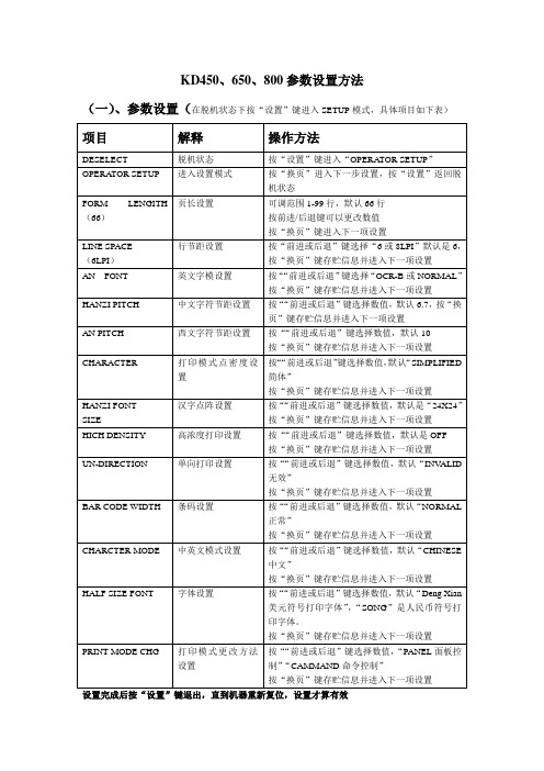
KD450、650、800参数设置方法(一)、参数设置(在脱机状态下按“设置”键进入SETUP模式,具体项目如下表)设置完成后按“设置”键退出,直到机器重新复位,设置才算有效(二)、维护工程师模式按“联机”+“测试”键三秒即可进入维护工程师三种诊断模式:1、设置模式:(1)设置项目(黑体代表默认设置值)①在接通打印机电源后加电模式(POWER ON MODE) (SELECT/DESELECT)②在缓冲器溢出时自动换行(AUTO LINE FEED)(NO/YES)③打印中检测到缺纸(OVERRIDE/TOP OF FORM)④回车代码功能(CR/LF)⑤在测试打印中跳页缝(YES/NO)⑥国际字符美国国/法国/德国/英国/丹麦1/瑞典/意大利/西班牙1/日本/挪威/丹麦2/西班牙⑦AN(数字字母)代码表(图形/斜体)(GRAPHICS/ITALIC)(2)设置方法按“联机”+“测试”健进入维护工程师诊断模式,按“前进”或“后退”键找到“SETUP MODE”模式,如下表所列:2、打印模式(用来检查打印质量)(1)打印项目①十六进制倾印打印(HEX DUMP PRINT)②测试样式打印(1- 9)(TEST PATTERN 1-9)③正常AN(数字字母)打印(PICA/ELITE)(NORMAL AN PRINT)④OCR-B AN 打印(PICA/ELITE)⑤实心AN(数字字母)打印(SOLID AN PRINT)⑥汉字水平打印(HANZI HORIZONTAL PRINT)⑦汉字垂直打印(HANZI VERTICAL PRINT)⑧ALL CG 打印(打印程序版本字体数据版本行数和当前设置参数值)⑨错误记录打印(ERROR LOG PRINT)(2)打印测试操作按“联机”+“测试”健进入维护工程师诊断模式,按“前进”或“后退”键找到“PRINT MODE”模式,如下表所列:附:ALL CG PRINT样张及解释3、测试模式(1)测试项目①硬件测试②面板开关测试③EEPROM 初始化④相位设置(120DPI/180DPI/90DPI)⑤页顶调整⑥下载模式选择⑦诊断模式选择(SIMPLE/FULL)附:关于开机诊断测试选项的说明将检查除下列错误信息以外的所有测试项目①当诊断测试设置为简单(SIMPLE)时(缺省) ②当诊断测试设置为完全(FULL)时。
AEMC模型6505 Megohmmeter产品介绍说明书

2119.87
Leads 5kV rated, set of three, 45 ft color-coded with color-coded clips; one red, one blue and one black with integral 5kV hippo clips (rated 5000V)
Short Circuit Current Accuracy 10kΩ to 40GΩ 40GΩ to 10TΩ DAR (1 min/30 sec)
500V 1000V 2500V 5000V
30kΩ to 2000GΩ (2TΩ) 100kΩ to 4000GΩ (4TΩ) 100kΩ to 10,000GΩ (10TΩ) 300kΩ to 10,000GΩ (10TΩ) 40 to 1000V: 10V increments 1000 to 5100V: 100V increments
Megohmmeters
Features
• True Megohmmeter® • Simple operation • Test voltage combination of 500V, 1000V,
2500V and 5000V • Insulation measurements from 30kΩ
<1.6mA ± 5%
±5% of Reading ± 3cts ±15% of Reading ± 10cts
0.02 to 50.00
PI (10 min/1 min & user programmable)
0.02 to 50.00
Capacitance Measurement
0.005 to 49.99µF; Max resolution 1nF
GMG软件使用说明_通用

GMG软件使用说明一、测试环境:打印机:Epson7600墨水:Epson原装墨水纸张:Fantac190软件:GMG Colorproof 4.5.2仪器:X-Rite i1二、系统设置及软件安装(一)系统设置1.在系统属性的“高级”标签下,点性能选项的“设置”按钮。
2.在设置面板的“视觉效果”标签下,选择“调整为最佳性能”选项。
3.在设置面板的“高级”标签下,分别选择处理器计划下的“程序”选项、内在使用下的“程序”选项。
4.在设置面板的“高级”标签下,点虚拟内存项的“更改”按钮,一般将虚拟内存设为物理内存的2倍。
(二)软件安装1.运行软件安装程序,在进行到选择安装位置时,选择自定义文件夹。
C:\Porgramfiles下建立GMG文件夹,将程序安装在所建立的文件夹中。
2.由于我们购买的软件锁定了中文语言,所以在安装时无论选择什么语言,程序运行时都是中文语言。
3.如果安装过程出现驱动程序未经数据验证的对话框,选择继续安装。
三、安装、测试打印机(一)安装打印机1.使用打印机自带软件安装打印机的驱动。
2.打印机联机:推荐使用USB2.0接口连接打印机。
(二)测试打印机1.在安装的打印机名称点右键,选择“属性”。
2.在出现的打印机属性面板中点“打印测试页”,测试打印机是否正常联机。
3.打印出打印机测试条,检查墨头是否正常。
若有断线,则清洗打印头,直到没有断线为止。
四、GMG Col orproof中的打印机配置1.运行GMG Colorproof 04(建议将快捷方式放在桌面)。
2.下图是没有设置打印机的界面。
3.双击左侧打印机图标,或在打印机菜单下选择“新打印机…插入”后出现下面对话框。
在列表中选择支持的打机印后,选择“是”。
4.在“共用”面板,填写打印名(名称可自己选择,要易于辨别)、选择系统中已经安装的打印机。
5.在打印机面板(此处以7600为例),进行如下设置。
在更多设置中的墨水类型改为照片黑。
GMG操作流程-io
GMG操作流程一、软件简介1.软件组成(1) GMG Colorproof打印机配置,使用校准向导校准打印机,手动开始一个作业和热文件夹安装.(2) GMG 色彩管理文件编辑器创建和编辑mx3, mx4 色彩管理文件测试图表的测量方法。
mx3 文件是校准文件,而mx4 文件描述的是特殊装置的特性.(3) GMG 专色编辑器创建和编辑专色数据库。
(4) GMG Rip 服务器Colorproof 一样支持PS、PDF、EPS文件。
2.软件的结构文件(1) 打印机校准文件*.mx3mx3 文件是一个用于校准颜色的三维色彩管理文件.它为印刷设备定义了特殊的媒介/油墨的结合。
如果打印机属性出现了偏差,该定义好的色彩标准可以让您再次校准使用GMG Colorproof 的打印机,因此,您可以稳定重复的得到色彩准确的样张。
(2) 全范围文件(Gamut File)*.csc一个全范围文件描述了一台打印机的最大色彩容量。
当从对象值计算和从目标和当前设备值计算时需要全范围文件.有两种不同类型的全范围文件:用于mx4 彩色profile 文件的“一般”全范围文件和用于打印机校准和特殊色彩的色彩管理文件的“完全全范围”文件.全范围文件描述了打印机的整个的、无限制的色域空间,其能够满足打印机校准的需求.用于打印机校准的简化色域空间常用于计算一个mx4/mx5 的色彩管理文件。
(3) 彩色色彩管理文件*.mx4这是一个用于从CMYK 到CMYK 转换的四维与设备相关的色彩管理文件。
当打印连续调样张(用于印刷机的非模拟网点图案的色彩匹配样张)时使用该文件。
该色彩管理文件使用纸张、油墨和根据目标值校准的印刷机的特定组合(如胶印)模拟打样,描述打样机的输出特性.(4)模板文件*.tpl模板文件是一个关于几何、排列以及为特殊的测量装置而配置的带有测试图表的色彩图解的记录文件.(5) 控制条文件*。
tif, *.gmg控制条是TIFF 文件格式(二值和连续)的印刷工艺控制条,它可以随样张一起被打印出来。
- 1、下载文档前请自行甄别文档内容的完整性,平台不提供额外的编辑、内容补充、找答案等附加服务。
- 2、"仅部分预览"的文档,不可在线预览部分如存在完整性等问题,可反馈申请退款(可完整预览的文档不适用该条件!)。
- 3、如文档侵犯您的权益,请联系客服反馈,我们会尽快为您处理(人工客服工作时间:9:00-18:30)。
GM650TestTool V1.0 使用说明 V1.0深圳市有方科技有限公司 有无线,方精彩Let's enjoy the wireless life!GM650TestTool v1.0 使用说明 V1.0版权声明Copyright © 2008 Neoway Technology 深圳市有方科技有限公司保留所有权利。
是深圳市有方科技有限公司所有商标。
本手册中出现的其他商标,由商标所有者所有。
说明本指南的使用对象为系统工程师,开发工程师及测试工程师。
由于产品版本升级或其它原因,本手册内容会在不预先通知的情况下进行必要的更新。
除非另有约定,本手册中的所有陈述、信息和建议不构成任何明示或暗示的担保。
深圳市有方科技有限公司为客户提供全方位的技术支持,任何垂询请直接联系您的客户经理 或发送邮件至以下邮箱: Sales@ Support@ 公司网址:深圳市有方科技有限公司版权所有 第 2 页,共 7 页 GM650TestTool v1.0 使用说明 V1.0目1 2 3录 概述 ....................................................................5 功能使用说明 ............................................................5 常见问题及解决办法 ......................................................6 深圳市有方科技有限公司版权所有 第 3 页,共 7 页 GM650TestTool v1.0 使用说明 V1.0修版本号 V1.0 更改内容 初始版本 订记录生效年月 2012‐07 深圳市有方科技有限公司版权所有 第 4 页,共 7 页 GM650TestTool v1.0 使用说明 V1.01 概述 GM650TestTool 是专门为 GM650 模块开发的一款测试软件工具, 用于测试 GM650 模块 GPS 模组的性能。
主要测试项目包括:搜星速度的计算,信号强度的柱状图显示,参数的解析及列表 显示,当前位置和移动轨迹的地图显示等。
请注意:在运行 GM650TestTool 前,请务必安装 Google Earth 软件,否则将无 法 正 常 启 动 运 行 。
GM650TestTool 支 持 的 Google Earth 软 件 包 全 称 为 “googleearthwin-peruser” ,可以向本公司索取。
GM650TestTool V1.0 目前只在 Win XP 运行测试完成, 其它操作系统未进行验证。
2 功能使用说明 本软件启动时会自动关联打开 Google Earth,然后会出现图 1 所示界面。
串口输入 接收框 字符串输入框 可输入 AT 命令 串口设置框 数据定位 信息框 图 1 主界面 深圳市有方科技有限公司版权所有 第 5 页,共 7 页 GM650TestTool v1.0 使用说明 V1.01、 在“串口设置”框中选择当前与 GM650 模块连接的串口,设置正确的波特率,然后点击“打 开串口” 。
2、 点击“开启 GPS”按键,串口输入接收框回显 at+gpspwr=1,说明 GPS 功能已经正常开启。
3、 点击“取 GPS 数据”按键,串口输入接收框回显接收到的 GPS 数据,同时,数据定位信息框 会显示当前获取 GPS 数据分析后得到的定位信息,定位后会在 google earth 上显示当前位置。
4、 “启动测试”按键是“开启 GPS”和“取 GPS 数据”两个按键的功能组合,且每隔 1 秒钟, 会在串口输入接收框回显 GPS 数据,并在数据定位信息框显示定位信息。
5、 “停止测试”和“关闭 GPS”按键均是用于停止 GPS 数据的接收、回显和定位分析。
6、 GPS 定位成功后会在主界面显示定位时间“X 秒定位” ,且关闭 GPS 和停止测试时定位时间不 会清空。
7、 “地图刷新间隔” 是手动设定当前接收到的 GPS 数据分析得到的地理位置信息在 google earth 上显示定位位置与上一次在 google earth 上显示定位位置的时间间隔。
8、 在字符串输入框中输入 AT 指令,点击“发送” ,在串口输入接收框会有相应的指令输入和正 确的回显信息。
9、 主界面最上方红色柱状图表是收到的卫星数和信号强度,横坐标表示卫星的编号,纵坐标表 示信号强度。
10、 点击“清空接收框”按键,串口输入接收框数据被清空。
11、 点击“清空输入框”按键,字符串输入框数据被清空。
12、 点击“清空追踪信息”按键,数据定位信息对话框中的追踪信息被清空。
3 常见问题及解决办法 1、 打开串口,弹出窗口提示“没有发现此串口或被占用” 。
解决办法:查看当前串口是否被其他应用程序占用或者串口没有检测到。
若被其他应用程序 占用,应先关闭应用后重新选择串口。
若串口没有被检测到,可以拔掉串口重新插入,然后 选择对应的串口号。
2、 点击“启动测试”或者“开启 GPS”按键后,串口输入接收框没有数据返回。
原因:有可能是模块没有开机。
解决办法:给模块供电开机,然后重新选择串口、波特率,点击“启动测试”或“开启 GPS” 。
3、 点击“发送”后弹出窗口提示:请输入指令。
深圳市有方科技有限公司版权所有 第 6 页,共 7 页 GM650TestTool v1.0 使用说明 V1.0原因:没有在字符串输入框中输入 AT 指令。
