Ch11_Altera_LVDS
使用altera FPGA soft-CDR模式的SGMII接口实现
AN-518-2.0 应用笔记
本应用笔记讨论了使用 Stratix® V、Stratix IV、Stratix III,和 Arria® II FPGA 中的 soft- CDR 模式,实现串行千兆位介质无关接口 (SGMII) 的不同方面。 1 本文档中的信息专门适用于 Stratix® V、Stratix IV、Stratix III,和 Arria® II FPGA。 所支持的 Altera FPGA 包含了支持差分标准 ( 例如包括 1.25 Gbps 的各种速度的 LVDS) 的专用电路。这些器件的高速 LVDS I/O 支持许多高速网络、通信 I/O 互联标准,以及 包括 SGMII 的应用程序。 在 LVDS I/O 上支持 SGMII 可以实现高端口数量、低功耗和低成本的多点以太网 (GbE) 系统。您可以利用所支持的 FPGA 的 soft- CDR 模式实现 SGMII 系统。 Altera 通过 soft- CDR 模式和 TSE MegaCore® 中的 Altera® FPGA LVDS 硬宏,提供了完 整的 SGMII 解决方案 — 实现了物理编码子层 (PCS) 和介质访问控制器 (MAC) 的功能。 本应用笔记包含如下几方面内容:
LINE CARDS
f 要了解关于 SFP 的详细信息,请参阅 Small Form- factor Pluggable (SFP) Transceiver MultiSource Agreement (MSA) 文档。
Soft- CDR 连接钢缆 SFP 收发器
图 3 显示使用一个 Altera FPGA 连接到铜缆 SFP 模块的一个典型的 SGMII 系统连接。
Altera Stratix V FPGA提供RLDRAM 3存储器支持
RL AM DR 3存 储 器 支 持
A tr 公 司 发 布 了 S rt 系 列 F GA, 用 于 支 持 l a e t iV ax P 适
Mi o c n技术 公 司 的下 一 代 低 延 时 DRAM ( DRAM r RL 3存
2 m ta i F GA 系 列 并 拥 有 许 多 新 的 生 产 效 率 特 8 n S rt V P x 性, 这些 特 性 使 广 大 设 计 团 队 能 够 获 得 更 快 速 的 时 序 逼
近 , 而缩 短产 品 推 出市 场 的 时 间 。 从
风 河 与 L I 合 推 出 S联 网络 通 信 多核 解 决 方 案
采 用 外 部 存 储 器 时 , 自动 缩 短 设 计 时 间便 易 用 、 观 的 部 分 可 重 配 置 设 计 利 直 流 程 , 一 步 降 低 功 耗 和 整 体 系 统 成 本 。 同 时 , 新 推 进 最 出 的 IE 版 本 还 可 提 供 一 项 低 成 本 仿 真 方 案 , 持 嵌 S 支 入式 设计 流程 。 部 分 可 重 配 置 技 术 具 备 可 即 时 调 整 的 高度 灵 活 性 , 可 以大 幅 扩 充 单 一 F GA 的容 量 。在 器 件 运 行 中 , 计 人 P 设 员 可 对 F GA 某 些 区 域 进 行 重 新 编 程 , 此 加 入 新 的 功 P 藉 能 , 器 件 其余 部 分 正 在 运行 的应 用 则 完 全不 会 受 到 任 何 而 影 响 。部分 可 重 配 置 技 术 还 可 以帮 助 设 计 人 员 有 效 地 管
S r tx V ta i GX 和 S r tx V GA。 S r t GX ta i GS FP tai V x FPGA
Altera FPGA和 Xilinx-FPGA-引脚功能详解

XilinxFPGA引脚功能详细介绍注:技术交流用,希望对大家有所帮助。
IO_LXXY_# 用户IO引脚XX代表某个Bank内唯一的一对引脚,Y=[P|N]代表对上升沿还是下降沿敏感,#代表bank号2.IO_LXXY_ZZZ_# 多功能引脚ZZZ代表在用户IO的基本上添加一个或多个以下功能。
Dn:I/O(在readback期间),在selectMAP或者BPI模式下,D[15:0]配置为数据口。
在从SelectMAP读反馈期间,如果RDWR_B=1,则这些引脚变成输出口。
配置完成后,这些引脚又作为普通用户引脚。
D0_DIN_MISO_MISO1:I,在并口模式(SelectMAP/BPI)下,D0是数据的最低位,在Bit-serial模式下,DIN是信号数据的输入;在SPI模式下,MISO是主输入或者从输出;在SPI*2或者SPI*4模式下,MISO1是SPI总线的第二位。
D1_MISO2,D2_MISO3:I,在并口模式下,D1和D2是数据总线的低位;在SPI*4模式下,MISO2和MISO3是SPI总线的MSBs。
An:O,A[25:0]为BPI模式的地址位。
配置完成后,变为用户I/O 口。
AWAKE:O,电源保存挂起模式的状态输出引脚。
SUSPEND是一个专用引脚,AWAKE是一个多功能引脚。
除非SUSPEND模式被使能,AWAKE 被用作用户I/O。
MOSI_CSI_B_MISO0:I/O,在SPI模式下,主输出或者从输入;在SelectMAP模式下,CSI_B是一个低电平有效的片选信号;在SPI*2或者SPI*4的模式下,MISO0是SPI总线的第一位数据。
FCS_B:O,BPI flash 的片选信号。
FOE_B:O,BPI flash的输出使能信号FWE_B:O,BPI flash 的写使用信号LDC:O,BPI模式配置期间为低电平HDC:O,BPI模式配置期间为高电平CSO_B:O,在并口模式下,工具链片选信号。
altera-ddr2-sdram-ip核参数设置及读写时序(汇编)

1、Uniphy 整体框图:2、存储控制器连接图PHY的时钟与复位信号1、pll_ref_clk:PLL参考时钟输入。
2、global_reset_n:全局复位信号,对PLL和PHY里的所有逻辑单元进行复位。
3、soft_reset_n:软复位信号,对phy复位,不对PLL复位。
当soft_reset_n为低时,输出的afi_reset_n信号也为低。
3、各个模块间的接口信号3、1控制器与用户接口间使用的Avalon相关信号线:下表是本地接口信号,在altera例化的IP核里,本地用户接口使用的是avalon总线 Local_addr:指的是用户接口端的地址线,位宽计算方法如下:1)当只使用1pcs 外部存储器时:位宽=bank位宽+行位宽+列位宽-1;2)当使用多片片外存储器时:位宽=芯片位宽+bank位宽+行位宽+列位宽-1;计算位宽时减1 是因为用户数据接口宽度是memory侧数据宽度的两倍(memory 侧是在时钟的上升和下降沿都收发数据,而用户侧只在时钟的上升沿收发数据,假如用户读写数据的时钟频率与memory侧的数据频率相同,那么,在时钟上升沿来时,用户侧发送的数据位宽应是memory侧数据位宽的两倍)。
local_be:字节使能信号(用于向控制器写数据时),与memory侧的DM(data mask )信号作用一样,比如,当想使local_data的某8位数据无效,将local_be的对应位置0即可。
local_burstbegin:本地突发开始信号,当avalon总线开始突发读写时,将此信号置位‘1’。
(使用条件:本地接口是avalon总线,且memory侧的突发长度大于2)local_size:本地突发长度,即连续读或写的local_data个数。
长度不能超过ddr ip 核里配置的maximum avalon- mm burst length的长度。
local_wdata:本地写数据。
Altera第10代FPGA首款产品的四大优势
Altera第10代FPGA首款产品的四大优势
木易
【期刊名称】《电子技术应用》
【年(卷),期】2014(40)10
【摘要】Altera公司日前宣布开始出售第10代产品的第一个系列——非易失MAX 10 FPGA及其评估套件。
该产品采用TSMC的55mm嵌入式闪存工艺技术。
MAX 10 FPGA仅有3mm×3mm,却集成了最高50K逻辑单元、闪存模块(用
户闪存和双配置闪存)、模数转换器、嵌入式存储器和DSP模块、DDR3外部存
储器接口、软核Nios Ⅱ处理器实现嵌入式处理功能、最多500个用户I/O、集
成电源调节器。
【总页数】1页(P4-4)
【关键词】Altera公司;FPGA;产品;嵌入式闪存;外部存储器接口;DSP模块;优势;嵌入式存储器
【作者】木易
【作者单位】AET
【正文语种】中文
【中图分类】TN791
【相关文献】
1.Actel推动FPGA从引擎盖下应用进入关键的汽车传动和安全系统/恩智浦半导
体发表全球首款4路输入HDMI 1.3接收器TDA19978HL此款整合芯片无需外部
转换器,可加速电视设计流程并降低产品成本 [J],
2.Achronix发布全球首款Speedcore嵌入式FPGA IP产品 [J], 王颖
3.Achronix发布全球首款Speedcore嵌入式FPGA IP产品 [J], 王颖
4.Altera公开业界第一款集成了HBM2 DRAM和FPGA的异构SiP器件 [J],
5.Altera Quartus Ⅱ软件v14.1支持业界第一款具有硬核浮点DSP模块的FPGA实现TFLOP性能 [J],
因版权原因,仅展示原文概要,查看原文内容请购买。
LVDS SERDES Intel FPGA IP 发布说明说明书
LVDS SERDES Intel® FPGA IP Release NotesOnline VersionSend FeedbackRN-1188683575 2023.12.04Contents ContentsLVDS SERDES Intel® FPGA IP Release Notes (3)LVDS SERDES Intel FPGA IP (intel_lvds) v23.1.0 (3)LVDS SERDES Intel FPGA IP (intel_lvds) v23.0.0 (4)LVDS SERDES Intel FPGA IP v20.0.1 (4)LVDS SERDES Intel FPGA IP v20.0.0 (4)LVDS SERDES Intel FPGA IP v19.5.0 (4)LVDS SERDES Intel FPGA IP v19.4.0 (4)LVDS SERDES Intel FPGA IP v19.3.0 (5)LVDS SERDES Intel FPGA IP v18.1 (5)LVDS SERDES Intel FPGA IP v18.0 (5)Intel FPGA LVDS SERDES IP Core v17.1 (6)Altera LVDS SERDES IP Core v17.0 (6)Altera LVDS SERDES IP Core v14.1 (6)Altera LVDS SERDES IP Core v14.0 Arria 10 Edition (6)Intel Agilex 7 F-Series and I-Series General-Purpose I/O User Guide Archives (7)Intel Stratix 10 High-Speed LVDS I/O User Guide Archives (7)LVDS SERDES Intel FPGA IP User Guide Archives (7)LVDS SERDES Intel®FPGA IP Release Notes Send Feedback2LVDS SERDES Intel® FPGA IP Release NotesIf a release note is not available for a specific IP version, the IP has no changes in thatversion. For information on IP update releases up to v18.1, refer to the Intel®Quartus® Prime Design Suite Update Release Notes.Intel FPGA IP versions match the Intel Quartus Prime Design Suite software versionsuntil v19.1. Starting in Intel Quartus Prime Design Suite software version 19.2, IntelFPGA IP has a new versioning scheme.The Intel FPGA IP version (X.Y.Z) number can change with each Intel Quartus Primesoftware version. A change in:•X indicates a major revision of the IP. If you update the Intel Quartus Primesoftware, you must regenerate the IP.•Y indicates the IP includes new features. Regenerate your IP to include these new features.•Z indicates the IP includes minor changes. Regenerate your IP to include these changes.Related Information•Introduction to Intel FPGA IP Cores•Intel Agilex® 7 LVDS SERDES User Guide: F-Series and I-Series•Intel Agilex® 7 LVDS SERDES User Guide: M-Series•Intel Stratix® 10 High-Speed LVDS I/O User Guide•LVDS SERDES Intel FPGA IP User Guide: Intel Arria® 10 and Intel Cyclone® 10 GX Devices•Intel Quartus Prime Design Suite Version 18.1 Update Release NotesLVDS SERDES Intel FPGA IP (intel_lvds) v23.1.0Table 1.v23.1.0 2023.12.04Intel Quartus Prime Version Description Impact23.4Added the Transmitter Settings tab to support tx_outclockwith these parameters:•Enable tx_outclock port•Desired tx_outclock phase shift (degrees)•Actual tx_outclock phase shift (degrees)•Tx_outclock division factor Upgrade and recompilation of the IP are required only if you want to use tx_outclock.Timing optimizations to make meeting setup and hold requirements easier.Upgrade and recompilation are not required.683575 | 2023.12.04Send FeedbackIntel Corporation. All rights reserved. Intel, the Intel logo, and other Intel marks are trademarks of IntelCorporation or its subsidiaries. Intel warrants performance of its FPGA and semiconductor products to current specifications in accordance with Intel's standard warranty, but reserves the right to make changes to any products and services at any time without notice. Intel assumes no responsibility or liability arising out of the application or use of any information, product, or service described herein except as expressly agreed to in writing by Intel. Intel customers are advised to obtain the latest version of device specifications before relying on any published information and before placing orders for products or services.*Other names and brands may be claimed as the property of others.ISO 9001:2015 RegisteredLVDS SERDES Intel FPGA IP (intel_lvds ) v23.0.0Table 2.v23.0.0 2023.10.02Intel Quartus Prime VersionDescriptionImpact23.3Added automatic bytes and pins selection in the pin settings tab.Related parameter changes:•TX_CH_*_BYTE changed to TX_CH_*_BYTE_USR •TX_CH_*_PIN changed to TX_CH_*_PIN_USR •RX_CH_*_BYTE changed to RX_CH_*_BYTE_USR •RX_CH_*_PIN changed to RX_CH_*_PIN_USRRecompilation of the IP is required.LVDS SERDES Intel FPGA IP v20.0.1Table 3.v20.0.1 2023.04.10Intel Quartus Prime VersionDescriptionImpact23.2Initial release of intel_lvds IP to support Intel Agilex ® 7 M-Series FPGAs and SoCs.—LVDS SERDES Intel FPGA IP v20.0.0Table 4.v20.0.0 2021.03.29Intel Quartus Prime VersionDescriptionImpact21.1•Optimized settings at the boundary between the FPGA fabric and I/O for LVDS SERDES IP use cases for Intel Agilex 7devices.Recompilation of the IP isrequired only for Intel Agilex 7devices.LVDS SERDES Intel FPGA IP v19.5.0Table 5.v19.5.0 2020.09.28Intel Quartus Prime VersionDescriptionImpact20.3Improved the power usage of the IP in Intel Agilex 7 devices.—Related InformationIntel Agilex General-Purpose I/O and LVDS SERDES User GuideLVDS SERDES Intel FPGA IP v19.4.0Table 6.v19.4.0 2020.04.13Intel Quartus Prime VersionDescriptionImpact20.1Add additional delay to the pll_locked signal assertion toensure the IP is properly locked to the PLL before IP initialization in Intel Agilex 7 devices.—LVDS SERDES Intel ® FPGA IP Release Notes683575 | 2023.12.04LVDS SERDES Intel ® FPGA IP Release Notes Send Feedback4Related InformationIntel Agilex General-Purpose I/O and LVDS SERDES User GuideLVDS SERDES Intel FPGA IP v19.3.0Table 7.v19.3.0 2019.12.16Intel Quartus Prime VersionDescriptionImpact19.4Added support for Intel Agilex 7 devices.—Related InformationIntel Agilex General-Purpose I/O and LVDS SERDES User GuideLVDS SERDES Intel FPGA IP v18.1Table 8.v18.1 September 2018Related Information •Introduction to Intel FPGA IP Cores•Intel Stratix 10 High-Speed LVDS I/O User Guide •LVDS SERDES Intel FPGA IP User GuideLVDS SERDES Intel FPGA IP v18.0Table 9.v18.0 May 2018DescriptionImpactRenamed the IP core from "Intel FPGA LVDS SERDES" to "LVDS SERDES Intel FPGA IP".-Related Information •Introduction to Intel FPGA IP Cores•Intel Stratix 10 High-Speed LVDS I/O User Guide •LVDS SERDES Intel FPGA IP User GuideLVDS SERDES Intel ® FPGA IP Release Notes 683575 | 2023.12.04Send FeedbackLVDS SERDES Intel ® FPGA IP Release Notes5Intel FPGA LVDS SERDES IP Core v17.1Table 10.v17.1 November 2017DescriptionImpactAdded support for Intel Stratix 10 devices:•Duplex feature to allow transmitter and receiver channels in the same I/O bank•Clock phase alignment (CPA) block for improved timing closure between the peripheryand the core —Renamed Altera LVDS SERDES IP core to Intel FPGA LVDS SERDES IP core as per Intel rebranding.—Related Information •Introduction to Intel FPGA IP Cores•Intel Stratix 10 High-Speed LVDS I/O User Guide •Intel FPGA LVDS SERDES IP Core User GuideAltera LVDS SERDES IP Core v17.0Table 11.v17.0 May 2017DescriptionImpactAdded support for Intel Cyclone ® 10 GX devices.-Related Information •Introduction to Intel FPGA IP Cores •Altera LVDS SERDES IP Core User GuideAltera LVDS SERDES IP Core v14.1Table 12.v14.1 December 2014DescriptionImpactAdded internal PLL additional clock export parameter-Related InformationAltera LVDS SERDES IP Core User GuideAltera LVDS SERDES IP Core v14.0 Arria 10 EditionTable 13.v14.0 Arria 10 Edition August 2014DescriptionImpactAdded feature that creates .sdc file for generated designs (previously only for example designs)-Added support for external PLL mode-Added option to clock TX core registers using reference clock-LVDS SERDES Intel ® FPGA IP Release Notes683575 | 2023.12.04LVDS SERDES Intel ® FPGA IP Release Notes Send Feedback6Related InformationAltera LVDS SERDES Megafunction User GuideIntel Agilex 7 F-Series and I-Series General-Purpose I/O User Guide ArchivesFor the latest and previous versions of this user guide, refer to Intel Agilex 7 General-Purpose I/O User Guide: F-Series and I-Series . If an IP or software version is not listed, the user guide for the previous IP or software version applies.IP versions are the same as the Intel Quartus Prime Design Suite software versions up to v19.1. From Intel Quartus Prime Design Suite software version 19.2 or later , IP cores have a new IP versioning scheme.If an IP version is not listed, the user guide for the previous IP version applies.Intel Quartus PrimeVersionUser Guide21.2Intel Agilex General Purpose I/O and LVDS SERDES User Guide 21.1Intel Agilex General Purpose I/O and LVDS SERDES User Guide 20.3Intel Agilex General Purpose I/O and LVDS SERDES User Guide 20.2Intel Agilex General Purpose I/O and LVDS SERDES User Guide 20.1Intel Agilex General Purpose I/O and LVDS SERDES User Guide 19.4Intel Agilex General Purpose I/O and LVDS SERDES User Guide 19.3Intel Agilex General Purpose I/O and LVDS SERDES User GuideIntel Stratix 10 High-Speed LVDS I/O User Guide ArchivesFor the latest and previous versions of this user guide, refer to Intel Stratix 10 High-Speed LVDS I/O User Guide . If an IP or software version is not listed, the user guide for the previous IP or software version applies.IP versions are the same as the Intel Quartus Prime Design Suite software versions up to v19.1. From Intel Quartus Prime Design Suite software version 19.2 or later , IP cores have a new IP versioning scheme.LVDS SERDES Intel FPGA IP User Guide ArchivesFor the latest and previous versions of this user guide, refer to LVDS SERDES Intel FPGA IP User Guide: Intel Arria ® 10 and Intel Cyclone 10 GX Devices . If an IP or software version is not listed, the user guide for the previous IP or software version applies.IP versions are the same as the Intel Quartus Prime Design Suite software versions up to v19.1. From Intel Quartus Prime Design Suite software version 19.2 or later , IP cores have a new IP versioning scheme.LVDS SERDES Intel ® FPGA IP Release Notes 683575 | 2023.12.04Send FeedbackLVDS SERDES Intel ® FPGA IP Release Notes7。
基于Altera FPGA的LVDS配置应用

基于Altera FPGA的LVDS配置应用一例在特权同学发表博文《Cyclone III的LVDS接口注意事项》后,不少网友发邮件询问LVDS具体应用的一些问题。
这些网友,归根到底,估计是文档看得太少了,或许还缺少动手实践的摸索。
做原型开发的知识储备,无外乎两种方式,要么理论,要么实践。
理论上前面说的文档是一方面,但是说理论不要被文档框住了,以为理论就是书本和文字。
其实换一个角度来理解理论,你也可以认为是间接获得知识的手段,包括一些可用的论坛资源、博文资源,甚至FAE资源等等。
不要金口难开,发个邮件打个电话,可能那些吃这个饭的FAE们一句话就帮你搞定问题了。
当然了,在你什么都没搞明白前,还是不建议你一通瞎问。
比较合适的方式是先自己去消化官方提供的文档,然后动手实践过程中实在是遇到百思不得其解的问题时再通过请教他人的方式得以解决。
而可能很多“菜鸟”百思不得其解的是文档到底从哪里找,茫茫网络浩如烟海,找个对口文档岂非易事?呵呵,其实,这个文档正可谓“众里寻他千百度,蓦然回首,那人却在灯火阑珊处”。
瞧,有心的朋友早已发现这个不是秘密的秘密了。
当我们使用Quartus II的MegaWizard选择并进入某个IP核的配置界面后,如图1所示,我们总能够在右上角看到一个名为“Documentation”的按钮,他就是传说中的“灯火阑珊处”了,点击后有两个二级子按钮,“On the Web”指向三级菜单的两个网络链接,“altlvds_tx Megafunction User Guide”则直接链接打开本地的帮助文档。
图1关于文档,除此以外,特权同学比较习惯的做法是在Quartus II handbook或Help中搜索关键词,如这里的altlvds_tx或LVDS,从而找到相关内容的介绍说明。
在实践前,这些理论知识的储备是必须的,否则咱的“高楼”很可能就是建立在“空穴”之上,指不定哪天就像咱上海前些年那座莲花河畔景苑一样在风雨过后居然楼体完整的“体面”倒下了。
AlteraFPGA开发板,FPGA主芯片采用Altera公司高性价

开发板的配置:Altera FPGA开发板,FPGA主芯片采用Altera公司高性价比FPGA,CycloneIV系列EP4CE6E22C8◦采用EPCS4SI8N串行配置芯片,同时支持JTAG和AS模式;◦采用50MHz有源晶振,提供系统工作时钟;◦采用电源芯片1117‐3.3V,提供3.3V电压输出;◦采用电源芯片1117‐2.5V,提供PLL电压;◦采用电源芯片1117‐1.2V,提供FPGA内核电压;◦采用5V直流电源插座和USB供电方式,两种供电方式方便开发板的使用◦采用红色电源指示灯及配置指示灯,准确的提示电源运行状况以及配置情况;◦采用自恢复保险丝、肖特基二极管的应用,大大提高了电路的可靠性和安全性;◦采用自锁按键电源开关;◦一个系统复位按键,为用户提供全局复位信息;◦一个重新配置按键,为用户提供重新配置信号;◦精心设计分配的I/O口,剩余I/O口全部引入扩展接口插座,方便用户进行二次开发;◦JTAG下载接口,一般用于测试过程中,对应下载的文件是SOF文件,下载速度快,但是掉电程序丢失;◦AS下载接口,一般用于固化程序,对应下载的是POF文件,下载速度相对较慢,但是掉电程序不丢失,在日常学习的中建议使用JTAG 方式;◦4位LED发光二极管(做流水灯,跑马灯,闪烁灯等实验)。
◦4位带冒号数码管(做动态或静态数码管显示,频率计,秒表等实验)。
◦一路蜂鸣器(用作发声实验)。
◦5只独立按键(做按键控制,按键消抖等实验)。
◦VGA接口(做VGA实验)。
◦usb转串口通讯电路(做和其他系统的串口通讯实验)。
◦1602LCD字符型液晶接口(做字符显示实验)。
◦12864LCD液晶接口(做汉字字符等显示实验)。
◦PS/2键盘接口(做PS/2键盘实验)。
◦时钟芯片(数字钟实验)。
◦DS18B20温度传感器(温度测试实验)。
◦红外(做红外遥控试验)◦64MB容量的SDRAM(做sdram实验)。
液晶显示器“TTL、LVDS”输出接口概述

液晶显示器“TTL、LVDS”输出接口概述1.TTL输出接口概述TTL(Transistor Transistor Logic)即晶体管-晶体管逻辑,TTL电平信号由TTL器件产生。
TTL器件是数字集成电路之一大门类,它采用双极型工艺制造,具有高速度、低功耗和品种多等特点。
TTL接口属于并行方式传输数据之接口,采用这种接口时,不必在液晶显示器之驱动板端和液晶面板端使用专用之接口电路,而是由驱动板主控芯片输出之TTL数据信号经电缆线直接传送到液晶面板之输人接口。
由于TTL接口信号电压高、连线多、传输电缆长,因此,电路之抗干扰能力比较差,而且容易产生电磁干扰(EMI)。
在实际应用中,TTL接口电路多用来驱动小尺寸(15in以下)或低分辨率之液晶面板。
另外,在笔记本电脑中也常使用1TL接口形式。
2.TTL输出接口之分类TTL输出接口可分为以下几类:(1)单路(或单通道)6bit TTL输出接口这种接口电路中,采用单路方式传输,每个基色信号采用6bit数据(R0~R5,CO~G5,B0~B5)。
由于基色RGB数据为18bit,因此,也称18位或18bit TTL接口。
(2)双路6bit TTL输出接口这种接口电路中,采用双路方式传输,每个基色信号采用6bit数据(奇路为0RO~OR5,OG 0~OG5,OB0~OB5;偶路为BRO~ER5,EC0~EG5,EB0~EB5)。
由于基色ROB数据为36bit,因此,也称36位或36bit rrL接口。
(3)单路8bit TTL输出接口这种接口电路中,采用单路方式传输,每个基色信号采用8bit数据(R0~R7,G0~G7,B0~B7)。
由于基色RGB数据为24bit,因此,也称24位或24bit 1TL接口。
(4)双路8bit TTL输出位接口这种接口电路中,采用双路方式传输,每个基色信号采用8bit数据(奇路为OR0~OR7,OG 0~0G7,OB0~OB7;偶路为ER0~ER7,EC0~EG7,EB0~EB7),由于基色RGB数据为48bit,因此,也称48位或48bit TTL接口。
FPGA的LVDS介绍和xilinx原语的使用方法中文说明

FPGA的LV DS介绍和x i linx原语的使用方法中文说明低压差分传送技术是基于低压差分信号(Low Volt-agc Differe ntialsignali ng)的传送技术,从一个电路板系统内的高速信号传送到不同电路系统之间的快速数据传送都可以应用低压差分传送技术来实现,其应用正变得越来越重要。
低压差分信号相对于单端的传送具有较高的噪声抑制功能,其较低的电压摆幅允许差分对线具有较高的数据传输速率,消耗较小的功率以及产生更低的电磁辐射。
LVDS:Low Voltage Differe ntialSignali ng,低电压差分信号。
LVDS传输支持速率一般在155Mbps(大约为77MH Z)以上。
LVDS是一种低摆幅的差分信号技术,它使得信号能在差分PCB线对或平衡电缆上以几百Mbps的速率传输,其低压幅和低电流驱动输出实现了低噪声和低功耗。
差分信号抗噪特性从差分信号传输线路上可以看出,若是理想状况,线路没有干扰时,在发送侧,可以形象理解为:IN= IN+ —IN-在接收侧,可以理解为:IN+ —IN- =OUT所以:OUT = IN在实际线路传输中,线路存在干扰,并且同时出现在差分线对上,在发送侧,仍然是:IN = IN+ —IN-线路传输干扰同时存在于差分对上,假设干扰为q,则接收则:(IN+ + q) —(IN- + q) = IN+ —IN- = OUT所以:OUT = IN噪声被抑止掉。
上述可以形象理解差分方式抑止噪声的能力。
From: 美国国家半导体的《LVDS用户手册》P9FPGA中的差分管脚为了适用于高速通讯的场合,现在的FPGA都提供了数目众多的LVDS接口。
如Spartan-3E系列FPG A提供了下列差分标准:LVDSBus LVDSmini-LVDSRSDSDiffere ntialHSTL (1.8V, Types I and III)Differe ntialSSTL (2.5V and 1.8V, Type I)2.5V LVPECLinputs所拥有的差分I/O管脚数目如下From:Spartan-3E FPGA Family:Complet e Data Sheet p5I/O管脚的命名方式:From:Spartan-3E FPGA Family:Complet e Data Sheet p164From:Spartan-3E FPGA Family:Complet e Data Sheet p18 Spartan-3E系列FPG A器件差分I/O接口输入工作的特性参数:From:Spartan-3E FPGA Family:Complet e Data Sheet p126 Spartan-3E系列FPG A器件差分I/O接口输出工作的特性参数:From:Spartan-3E FPGA Family:Complet e Data Sheet p127Xilinx公司差分原语的使用(原语,其英文名字为P rimiti ve,是Xilinx针对其器件特征开发的一系列常用模块的名字,用户可以将其看成Xilin x公司为用户提供的库函数,类似于C+ +中的“cout”等关键字,是芯片中的基本元件,代表FPGA中实际拥有的硬件逻辑单元,如LUT,D触发器,RAM等,相当于软件中的机器语言。
Altera宣布为高性能FPGA提供高效的电源转换解决方案

Altera 宣布为高性能FPGA 提供高效的电源转换解决
方案
2014 年4 月8 号,北京——Altera 公司(Nasdaq: ALTR)今天宣布开始提供新款电源转换解决方案,方便了电路板开发人员设计负载点电源方案,以最
低的系统功耗实现FPGA 最佳性能。
新款电源转换解决方案包括单片40A 驱动器和同步MOSFET 电源,经过优化,可以满足Altera 高性能Stratix®V、Arria® 10 以及Stratix® 10 FPGA 和SoC 的核心需求。
当系统设计人员需要将高性能FPGA 集成到系统中时,它为系统设计人员提供了高效的高密度电源
转换方案。
新款电源(型号ET4040)满足了高性能FPGA、处理器和存储器严格的内核电压需求。
系统设计人员可以利用40A 电源,采用单相或者多相配置,高效
的为FPGA 内核供电。
它还可以用在DDR3、DDR4 和QDR 存储器的VDDQ 供电电源中,也可以为高端服务器和通信基础设施系统中的ASIC 和ASSP
提供所有的大电流电源。
Altera 电源业务部市场总监Mark Davidson 评论说:“在过去几年中,Altera 交付了适用于Altera FPGA 和SoC 供电的各种解决方案,性能、功率密度和效率满足了系统开发人员的需求。
这一系列电源完善了Altera 的Power SoC DC-DC 转换器,这种体积最小、效率最高的电源解决方案为系统。
CH9121网络和UART透明传输芯片说明书
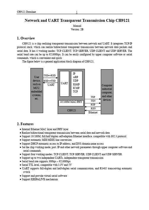
Network and UART Transparent Transmission Chip CH9121ManualVersion: 2B1.OverviewCH9121 is a chip realizing transparent transmission between network and UART. It integrates TCP/IP protocol stack, which can realize bidirectional transparent transmission between network data packets and serial data. It has 4 working modes: TCP CLIENT, TCP SERVER, UDP CLIENT and UDP SERVER. The serial baud rate can be up to 921600bps. It can be easily configured by upper computer software or serial commands, which is convenient and quick.The figure below is a general application block diagram of CH9121.2.Features●Internal Ethernet MAC layer and PHY layer●Realize bidirectional transparent transmission between serial data and network data●Support 10/100M, full/half duplex self-adaption Ethernet interface, compatible with 802.3 protocol●Support automatic MDI/MDIX line conversion●Support DHCP automatic access to IP address, and DNS domain name access●Set the chip working mode, port, IP and other network parameters through upper computer software andserial commands●Support four working modes: TCP CLIENT, TCP SERVER, UDP CLIENT and UDP SERVER●Support up to two independent UARTs, independent transparent transmission●Serial baud rate supports 300bps ~ 921600bps●Serial TTL level, compatible with 3.3V and 5V●UART supports full-duplex and half-duplex serial communication, and RS485 transceiving automaticswitch●Support and provide virtual serial software●Support KEEPALIVE mechanism3.PackageChipPackageName DescriptionCH9121 LQFP64M LQFP package; 64 pins; package body 10 x10mm 4.PinsCH9121 Pin No.PinNamePin Type Pin description2, 12, 17, 21, 29, 40, 42, 45, 63 VCC33 Power3.3V positive power input, require an external 0.1uF powerdecoupling capacitor6, 19, 28, 43, 54, 64 VCC18 Power1.8V positive power input, require an external 0.1uF powerdecoupling capacitor3, 9, 13, 18, 20,37, 41, 44, 48GND Power Common ground14, 15, 16, 22,23, 24, 25, 26,27, 34, 35, 38,39, 47, 49, 50,61, 62NC - Reserved, suspended1 RSETE Input Connected with an external 18K resistor to ground4 RXP EthernetsignalEthernet RXP signal5 RXN Ethernet Ethernet RXN signalsignal7 TXP EthernetsignalEthernet TXP signal8 TXN EthernetsignalEthernet TXN signal10 XI Input Input of the crystal oscillator, requires an external 30MHzcrystal11 XO Output Inverted output of crystal oscillator, requires an external 30MHzcrystal30 TCPCS1 Output In TCP client mode, connection status indicator of port 1, activeat low level31 RUN Output CH9121 running status indicator pin, multiplexed as ISPupgrade pin32 CFGEN Input Network configuration enable pin, detects when power-up, configuration disabled when at low level33 TCPCS2 Output In TCP client mode, connection status indicator of port 2, activeat low level36 RSTI Input External reset input, active at low level, built-in pull-up resistor 46 DIR2 Output Used to control RS485 receiving/transmitting switch of UART251 DIR1 Output Used to control RS485 receiving/transmitting switch of UART152 ACT# Output Ethernet connection communication indicator LED drive pin53 LINK# Output PHY connection indicator LED, active low55 RXD2 Input Serial data input of UART2, built-in pull-up resistor(Off by default)56 TXD2 Output Serial data output of UART2 (Off by default)57 RXD1 Input Serial data input of UART1, built-in pull-up resistor(On by default)58 TXD1 Output Serial data output of UART1 (On by default)59 RESET InputRestore factory settings, chip power-on detection, active at low level60 CFG0 InputUART configuration mode set pin, built in pull-up. If low level is detected, enter UART configuration mode. Exit the mode if high level is detected5.Function5.1. Function DescriptionCH9121 is a chip for transparent transmission between network and UART, and realizes bidirectional transparent transmission of serial data and network data. It supports 4 working modes (TCP CLEINT/SERVER, UDP CLIENT/SERVER), and the serial baud rate supported ranges from 300bps to 921600bps. Before use, the network parameters and UART parameters of the chip shall be configured by upper computer software NetModuleConfig.exe or serial commands. After the configuration is completed, CH9121 will save the configuration parameters to the internal storage space. And after the chip is reset, CH9121 will work according to the saved configuration value.The basic parameters of CH9121 include: name, MAC address display, dynamic access IP address setting, manual IP address setting (including CH9121 IP address, subnet mask, default gateway), and UART negotiation configuration.The name is mainly for the convenience of CH9121 module management within the LAN, with the length of not more than 20 bytes. The MAC address field shows the MAC address of the currently selectedmodule. There are two ways for CH9121 to set network parameters. 1) DHCP, that is, it automatically obtains network parameters from the gateway device with DHCP SERVER function; 2) manual setting. UART negotiation configuration function is to enter serial configuration mode by handshaking through the UART, which is disabled by default.CH9121 port parameters include: network mode, local port, target IP/domain name, destination port, serial baud rate/data bit/stop bit/parity check bit, network cable disconnection processing, RX packet length, RX packet timeout interval, network connection operation.The network mode (TCP SERVER/CLIENT, UDP SERVER/CLIENT), destination IP address, and local/destination port are the basic parameters of network communication. The destination IP address can also be accessed by domain name. The serial baud rate ranges from 300bps to 921600bps (the baud rate error of the serial port transmitting signal is less than 0.3%, and the allowable baud rate error of the serial port receiving signal is not less than 2%). It supports 5/6/7/8 data bits, 1/2 stop bits, odd/even/no parity check, blank 0, and mark 1 check mode. The network cable disconnection processing means that when the network cable is disconnected, CH9121 actively closes the connection or does not take any action. The length range of RX packet is 1-1024, which means that when the length of CH9121 UART receiving data reaches the set length, CH9121 will immediately packet the serial data and send it out via network. The timeout time setting range is 0-200, and the timeout unit is about 5ms. For example, when the timeout is 1, the data length of the serial port receiving buffer does not reach the length of the RX packet, and the serial port does not receive a new one in more than 5ms, the serial port timeout will occur. After the serial port timeout occurs, CH9121 will send the data received by the serial port over the network. When the timeout time is set to 0, the internal hardware timeout mechanism will be enabled (no new data is received after 4 data times), which is suitable for occasions where real-time requirements are high and large quantities of data are sent and received. Clear serial port buffer setting refers to how the data received by the serial port is processed before the network connection is established, the data is cleared (discarded) or retained after TCP connection.5.2. Default ConfigurationWhen CH9121 leaves factory, port 2 is closed and port 1 works in TCP CLIENT mode by default. The default parameters related to the network are as follows:(1)Device IP: 192.168.1.200(2)Subnet mask: 255.255.255.0(3)Default gateway: 192.168.1.1(4)Module port: 2000(5)Destination IP: 192.168.1.100(6)Destination port: 1000(7)Number of reconnection: unlimitedUART related default parameters are:(1)Baud rate: 9600(2)Timeout: 0(3)Data bit: 8. Stop bit: 1. Parity check bit: No(4)Clear UART buffer: Never6.Parameters6.1. Absolute Maximum ValueCritical value or exceeding the absolute maximum value may cause the chip to work abnormally or even be damaged.Name Parameter description Min. Max. UnitTA Ambient temperature during operation VCC33=3.3VVCC18=1.8V-40 85 ℃TS Ambient temperature during storage -55 125 ℃VCC33 Supply voltage (VCC33 connects to power, GND to ground) -0.4 4.2 V VCC18 Supply voltage (VCC18 connects to power, GND to ground) -0.4 2.3 V VIO Voltage on input or output pins -0.4 VCC33+0.4 V VIO5 Voltage on input or output pins that support 5V withstand voltage -0.4 5.4 V6.2. Electrical ParametersTest Conditions: TA=25℃, VCC33=3.3V, VCC18=1.8VName Parameter description Min. Typ. Max. UnitVCCxx Supply voltage VCC33 2.7 3.3 3.6V VCC18 1.65 1.8 1.95ICC Total supply current duringoperationVCC33=3.3V 160 190 mAVIL Low level input voltage -0.4 0.7 V VIH High level input voltage 2.0 VCC33+0.4 V VOL Low level output voltage (4mA draw current) 0.4 V VOH High level output voltage (4mA output current) VCC33-0.4 VIUP Input current at the input terminal with built-inpull-up resistor20 40 100 uAIDN Input current at the input terminal with built-inpull-down resistor-20 -40 -100 uAVR Voltage threshold when power-on reset 1.4 1.5 2.5 V7.Applications7.1 Hardware Circuit DesignNote: Due to space limitations, the circuit of the power supply and decoupling capacitors near the 3.3V and 1.8V pins is omitted in the figure, which must be added when designing the circuit. The detailed circuit reference file: CH9121PCB (please download in our official website).U1 is the main control chip CH9121. TXD1 and RXD1 are compatible with 3.3V and 5V level, and the RS485 control pin DIR can be suspended if not used.P1 is RJ45 port, with built-in network transformer, used to connect network equipments such as switches and router. It contains two pairs of Ethernet differential signals.When actually making a PCB, R5-R8, C6, and C7 should be as close as possible to the 5th pin of P1. The 0.1 uF decoupling capacitors for 3.3V and 1.8V pins are omitted in the figure. TXOP (RXIP) and TXON. (RXIN) are differential signals. When wiring, they should be wired close to parallel, and try to provide ground wire or copper coating on both sides to reduce external interference. The length of relevant signals of crystals XI and XO should be shortened as much as possible. In order to reduce the interference of high-frequency clock for the outside, the baselines should be surrounded or copper should be clad around relevant components.。
Altera发售其首款SoC,和ARM合作DS-5工具包
暗光视频采集成监控热点
2012年12月初的中国国际公共安 全博览会 (CPSE)个亮点 是光线条件差时的视频采集方案。
TI达芬奇处理器实现更低照度 德州仪器(TI)推出了达芬奇
DM385与DM8107视频处理器,可通 过使用独特的低照技术与高效率压缩 功能,为客户提供高质量视频解决方 案,满足视频安全 IP 摄像机与录制系 统的需求。
责任编辑:薛士然
New Products 产 品 推 介
Altera:发售其首款SoC,和ARM合作DS-5工具包
Altera发售其第一款SoC器件 不久前,Altera宣布首次发售其
28 nm SoC器件,在一片器件中同时实 现了双核ARM Cortex-A9处理器系统和 FPGA逻辑。Altera SoC含有多种独特 的功能,支持无线通信、工业、视频 监控、汽车和医疗设备市场的开发人 员开发定制SoC型号产品,优化满足 了系统功耗、电路板面积,以及性能 和成本需求。Altera发售的第一款器件 是低功耗、低成本Cyclone V SoC。
Lattice与ACAMAR合作图像传 感器
莱迪思(Lattice)半导体公司展 出了多款新的基于FPGA的摄像机 设计,其中新的WDR(宽动态范围) 图像传感器解决方案是和ACAMAR 合作,该SDI(串行数字接口)摄像头 方案采用LatticeECP3 FPGA的SDI摄 像头、Acamar的ACM701。ACM701 支持720P,并且是Acamar第一款配 备BEYONDVISION的摄像头产品。
BEYONDVISION是一种独特的图像处 理技术,实现了高清、光线条件差的 情况下良好的图像质量、扩展的动态 范围,以及在所有光照条件下忠实的 色彩还原能力。ACM701采用了低成 本、低功耗的LatticeECP3FPGA,该 器件提供了所有高清摄像头的特性和 功能。
基于Altera FPGA的LVDS配置应用

基于Altera FPGA的LVDS配置应用一例在特权同学发表博文《Cyclone III的LVDS接口注意事项》后,不少网友发邮件询问LVDS具体应用的一些问题。
这些网友,归根到底,估计是文档看得太少了,或许还缺少动手实践的摸索。
做原型开发的知识储备,无外乎两种方式,要么理论,要么实践。
理论上前面说的文档是一方面,但是说理论不要被文档框住了,以为理论就是书本和文字。
其实换一个角度来理解理论,你也可以认为是间接获得知识的手段,包括一些可用的论坛资源、博文资源,甚至FAE资源等等。
不要金口难开,发个邮件打个电话,可能那些吃这个饭的FAE们一句话就帮你搞定问题了。
当然了,在你什么都没搞明白前,还是不建议你一通瞎问。
比较合适的方式是先自己去消化官方提供的文档,然后动手实践过程中实在是遇到百思不得其解的问题时再通过请教他人的方式得以解决。
而可能很多“菜鸟”百思不得其解的是文档到底从哪里找,茫茫网络浩如烟海,找个对口文档岂非易事?呵呵,其实,这个文档正可谓“众里寻他千百度,蓦然回首,那人却在灯火阑珊处”。
瞧,有心的朋友早已发现这个不是秘密的秘密了。
当我们使用Quartus II的MegaWizard选择并进入某个IP核的配置界面后,如图1所示,我们总能够在右上角看到一个名为“Documentation”的按钮,他就是传说中的“灯火阑珊处”了,点击后有两个二级子按钮,“On the Web”指向三级菜单的两个网络链接,“altlvds_tx Megafunction User Guide”则直接链接打开本地的帮助文档。
图1关于文档,除此以外,特权同学比较习惯的做法是在Quartus II handbook或Help中搜索关键词,如这里的altlvds_tx或LVDS,从而找到相关内容的介绍说明。
在实践前,这些理论知识的储备是必须的,否则咱的“高楼”很可能就是建立在“空穴”之上,指不定哪天就像咱上海前些年那座莲花河畔景苑一样在风雨过后居然楼体完整的“体面”倒下了。
AlteraCycloneIILVDS学习总结

AlteraCycloneIILVDS学习总结Altera Cyclone II LVDS学习总结-⽆情剑客lufy(282094986)LVDS电平标准:LVDS是对应⼀种⾼速差分信号,对于Cyclone II可输⼊⾼达805Mbps,输出⾼达640Mbps。
对应LVDS电平IO的Place推荐:1,Single-ended IO Input⾄少要离⼀个LVDS IO 4个Pad远。
2,Single-ended IO Output⾄少要离⼀个LVDS IO 5个Pad远。
3,平均每⼀对VCCIO和GND对最⼤可⽀持4个155MHz(或者更⼤)的的输出IO;4,平均每⼀对VCCIO和GND对最⼤可⽀持3个311MHz(或者更⼤)的的输出IO;对应Cyclone II,对应每个Bank都⽀持LVDS标准电平。
具体见IO定义。
对应在Cyclone IV中,对应Cyclone IV GX只有right-Bank⽀持True LVDS。
⽽对应Cyclone E中,左右Bank均⽀持True LVDS。
对应上下Bank是通过Single-Ended Output Buffer以及外部电阻组合成LVDS。
对应应⽤True Lvds硬件连接:对应应⽤上下Bank LVDS硬件连接AltLvds这个IP⽤法讲解:AltLvds这个IP应⽤包括AltLvds-RX和AltLvds-TX这两个IP对。
下表对应就是ALTLVDS-RX和ALTLVDS-TX对应特性:通过表中知道对应Cyclone系列,⽆对应专⽤硬件实现电路实现LVDS的收发。
同时对应在ALTLVDS-RX中,对应不⽀持动态相位监测以及校准功能,以及时钟恢复功能。
对应⽀持此IP的器件系列:Parameter Setting以下对应就是ALTLVDS-RX和ALTLVDS-TX的参数设置对应这个参数设置对应将Deserializer电路采⽤内部LE单元实现。
altera的lvds用法
altera的lvds用法Altera(现在归属于英特尔)的FPGA(现在称为Intel FPGA)在实现LVDS(Low Voltage Differential Signaling)时,通常会使用Altera LVDS IP 核或采用LVDS I/O 标准。
下面是一般情况下使用Altera FPGA 实现LVDS 的步骤:1. 引脚规划(Pin Assignment):-在Quartus Prime 设计工具中,打开项目并打开Pin Planner。
-选择LVDS 输入或输出引脚。
-将LVDS 信号与适当的FPGA 引脚相连。
2. 时钟资源分配:-如果LVDS 信号需要与时钟一起使用,确保为LVDS 时钟引脚分配了正确的时钟资源。
- Altera FPGA 提供PLL(Phase-Locked Loop)资源,可用于产生LVDS 时钟。
3. 使用LVDS IP 核:-在Quartus Prime 中,你可以使用IP Catalog 中的"ALTDDIO_IN" 和"ALTDDIO_OUT" IP 核。
-在IP Catalog 中搜索"ALTDDIO_IN" 或"ALTDDIO_OUT",然后将其添加到你的设计中。
-在IP 核配置中,设置LVDS 参数,如输入/输出模式、电压标准等。
4. 约束设置:-在设计中,你可能需要添加SDC(Synopsys Design Constraints)文件,以确保时序约束得到满足。
-针对LVDS 时序进行适当的约束,确保时序满足LVDS 标准。
5. 仿真和验证:-在设计完成后,进行仿真以验证LVDS 信号的正确性。
-使用SignalTap 或其他调试工具来监视LVDS 信号。
6. 生成配置文件和下载到FPGA:-在Quartus Prime 中,使用编译工具生成配置文件。
-使用Programmer 工具将配置文件下载到FPGA 中。
- 1、下载文档前请自行甄别文档内容的完整性,平台不提供额外的编辑、内容补充、找答案等附加服务。
- 2、"仅部分预览"的文档,不可在线预览部分如存在完整性等问题,可反馈申请退款(可完整预览的文档不适用该条件!)。
- 3、如文档侵犯您的权益,请联系客服反馈,我们会尽快为您处理(人工客服工作时间:9:00-18:30)。
Timing Budget Example
SW = 0.44 ns, TCCS = 0.4 ns RSKM = (TUI – SW – TCCS) / 2 = (1.6 – 0.44 – 0.4) / 2 = 380 ps Cable skew per meter (max) = 50 ps, Connector skew (max) = 17 ps PCB skew = 30 ps (based on the electrical length of the PCB traces) System skew = Cable skew + Connector skew + PCB skew = 50 ps/m× 5 m + 17 ps + 30 ps = 297 ps Margin = RSKM – (input clock jitter + system skew) = 380 ps – (10 ps + 297 ps) = 73 ps
Why LVDS?
High speed data transfer applications Extremely high-performance solution with a minimum of power Strict EMI requirements Immune to noise Costs
IEEE
LVDS Owner's Manual – 2nd Edition
National Semiconductor
What is LVDS?
A low-voltage swing, general-purpose I/O standard
IEEE Std. 1596.3 SCI-LVDS (250 Mbps) ANSI/TIA/EIA-644 (840 Mbps)
(Bi-Directional Half-Duplex Configuration)
LVDS Configurations
(Multidrop Configuration)
LVDS Transmitter & Receiver (Board Skew)
Problems Caused By Board Skew
LVDS Signal Level
Why Low Swing Differential?
Noise is coupled onto the two wires as common-mode which can be rejected easily Radiate less noise than single-ended signals due to the canceling of magnetic fields Current-mode driver is not prone to ringing and switching spikes, further reducing noise.
PLD
LVDS in Altera Device
Reference
Application Note 120
Using LVDS in APEX 20KE Devices
Altera White Paper
Board Design Guidelines for LVDS Systems
Altera
IEEE standard for Low-Voltage Differential Signals (LVDS) for Scalable Coherent Interface (SCI)
Common-Noise Testing
Signals
Max. Common-Mode Noise
A Quick Comparison between Differential Signaling Technologies
Power Consumption Compare With LVCMOS
Serial to Parallel
Data Format
LVDS Driver & Receiver
LVDS Current-Mode Driver
■ Increased performance ■ Reduced power consumption ■ Minimized electromagnetic interference (EMI) generation
isolation
Crosstalk Between LVDS & Single-Ended Signals (2)
EMI (1)
Considerably higher (typically one and a half times) propagation times than that of microstrip Need additional vias Need more layers Difficulty in achieving 100 differential impedance accurately
Shield Cable For LVDS Signals
Differential traces
LVDS Driver
LVDS Receiver
Impedance Matching
00805 or 0603 SMD Resistor
<7mm
Crosstalk Between LVDS & Single-Ended Signals (1)
Connectors must have low skew with matched impedance. Connectors with same length leads should be selected for lower skew and crosstalk. The two members of the same differential pair must be placed adjacent to each other on the connector Ground pins should be placed between differential pairs. End pins of the connectors should preferably be grounded and must not be used for high speed signals. All the unused pins of the connector should be properly terminated
LVDS Transmitter Logic Design
PCB Design Considerations
Differential traces Impedance Matching Crosstalk Between LVDS & SingleEnded Signals Electromagnetic Interference
difference between the fastest & slowest data output transitions
Sampling Window
Caused by different delay of data trace
Channel-to-Channel Skew (TCCS)
Timing Budget
LVDS Connectors (2)
�
Output Timing Waveform
LVDS Receiver Block Diagram
PLLs For LVDS in APEX 20KE
LVDS Transmitter Block Diagram
LVDS Receiver & Transmitter Interface
LDVS IO Banks in APEX20K
High Speed LVCMOS Circuits (256 IO pins)
High Speed LVDS Circuits (256 IO pins)
LVDS Configurations (Point-to-Point Configuration)
LVDS Configurations
EMI (2)
make S < 2W, S < B, and D > 2S
Bypassing the Supply Planes
LVDS Cables
Ribbon Cable for Low Speed LVDS Applications
Coaxial & Twin-axial Cables
LVDS Connectors (1)
Extremely high-speed
PCB traces, backplanes, and cables 840 megabits per second (Mbps)
Low-power
lo
Low-noise
low-voltage differential signal
Deskew Circuitry Calibration Waveform
Timing of D-FF
A D CLK CLK A Hold time Q B D CLK Q C
CLK B C
Eye Pattern of LVDS
LVDS Eye Diagram at 840 Mbps
LVDS Timing
Transmitter PLL Clocks Receiver PLL
Receiver PLLs Clocked by Board Clock
Data Feeds LEs Directly
For low data rate LVDS signals that are less than 155 Mbps,
