【用户手册】CANSwitch-AN2S2高性能双路CAN转以太网交换机用户手册V1.00
Q-SYS NS Series Gen 2 网络交换机快速入门指南说明书
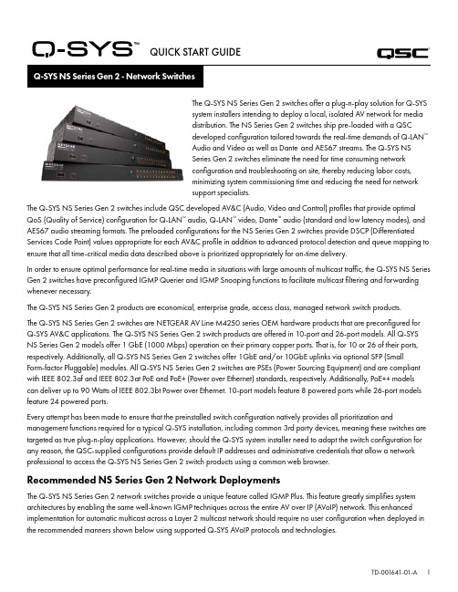
QUICK START GUIDE®The Q-SYS NS Series Gen 2 switches offer a plug-n-play solution for Q-SYSsystem installers intending to deploy a local, isolated AV network for mediadistribution. The NS Series Gen 2 switches ship pre-loaded with a QSCdeveloped configuration tailored towards the real-time demands of Q-LAN™Audio and Video as well as Dante and AES67 streams. The Q-SYS NSSeries Gen 2 switches eliminate the need for time consuming networkconfiguration and troubleshooting on site, thereby reducing labor costs,minimizing system commissioning time and reducing the need for networksupport specialists.The Q-SYS NS Series Gen 2 switches include QSC developed AV&C (Audio, Video and Control) profiles that provide optimal QoS (Quality of Service) configuration for Q-LAN™ audio, Q-LAN™ video, Dante™ audio (standard and low latency modes), and AES67 audio streaming formats. The preloaded configurations for the NS Series Gen 2 switches provide DSCP (Differentiated Services Code Point) values appropriate for each AV&C profile in addition to advanced protocol detection and queue mapping to ensure that all time-critical media data described above is prioritized appropriately for on-time delivery.In order to ensure optimal performance for real-time media in situations with large amounts of multicast traffic, the Q-SYS NS Series Gen 2 switches have preconfigured IGMP Querier and IGMP Snooping functions to facilitate multicast filtering and forwarding whenever necessary.The Q-SYS NS Series Gen 2 products are economical, enterprise grade, access class, managed network switch products.The Q-SYS NS Series Gen 2 switches are NETGEAR AV Line M4250 series OEM hardware products that are preconfigured forQ-SYS AV&C applications. The Q-SYS NS Series Gen 2 switch products are offered in 10-port and 26-port models. All Q-SYS NS Series Gen 2 models offer 1 GbE (1000 Mbps) operation on their primary copper ports. That is, for 10 or 26 of their ports, respectively. Additionally, all Q-SYS NS Series Gen 2 switches offer 1GbE and/or 10GbE uplinks via optional SFP (SmallForm-factor Pluggable) modules. All Q-SYS NS Series Gen 2 switches are PSEs (Power Sourcing Equipment) and are compliant with IEEE 802.3af and IEEE 802.3at PoE and PoE+ (Power over Ethernet) standards, respectively. Additionally, PoE++ models can deliver up to 90 Watts of IEEE 802.3bt Power over Ethernet. 10-port models feature 8 powered ports while 26-port models feature 24 powered ports.Every attempt has been made to ensure that the preinstalled switch configuration natively provides all prioritization and management functions required for a typical Q-SYS installation, including common 3rd party devices, meaning these switches are targeted as true plug-n-play applications. However, should the Q-SYS system installer need to adapt the switch configuration for any reason, the QSC-supplied configurations provide default IP addresses and administrative credentials that allow a network professional to access the Q-SYS NS Series Gen 2 switch products using a common web browser.Recommended NS Series Gen 2 Network DeploymentsThe Q-SYS NS Series Gen 2 network switches provide a unique feature called IGMP Plus. This feature greatly simplifies system architectures by enabling the same well-known IGMP techniques across the entire AV over IP (AVoIP) network. This enhanced implementation for automatic multicast across a Layer 2 multicast network should require no user configuration when deployed in the recommended manners shown below using supported Q-SYS AVoIP protocols and technologies.Example A: Completely Isolated SystemsIn this scenario, individual Q-SYS systems within a facility are completely isolated islands with their own dedicated networks and no interaction with, or connection to, other systems or the facility’s infrastructure and services.This scenario will work completely turnkey with no adjustments to the switches required.Room 1Room 2Room 3Example B: Completely Isolated Systems with Switch ManagementIn many facilities with existing infrastructure and/or IT staff on hand, they may desire a connection to the AV switches for basic monitoring or management. The Q-SYS NS Series Gen 2 switches feature an OOB (Out of Band) port that can be used for direct access to the switch’s management functions without the need to connect to the AV network(s). This OOB port is configured for DHCP and will fall back to 192.168.0.239 if no DHCP service is available. Note: It may take up to 5 minutes for the OOB port to fall back to its default IP after initial power on or a reboot.Example C: Centralized System Management, Access to Corporate Services and/or InternetThe following is the most common deployment scenario for Q-SYS Systems. In this scenario, the systems are still largely isolated with respect to real-time, multicast, and high-bandwidth AV traffic, but the Core’s LAN B or AUX connections are used to provide centralized management, integration with corporate services such as VoIP, or provide the Cores access to the Internet for remote management and monitoring through Q-SYS Reflect Enterprise Manager. Refer to the Q-SYS Designer Help file for information on configuring the specific services present on a Core’s LAN B or AUX connection.Example D: Integrating Q-SYS SystemsIn some cases, it may be desirable to share content between systems or integrate a facility’s centralized paging and background music distribution. As long as only Q-SYS NS Series Gen 2 switches are interconnected, attention is paid to the bandwidth utilization of ISLs (Inter-Switch Link), and care is taken to avoid IP address conflicts as documented further on, the unique QSC configurations and IGMP Plus features of the Q-SYS NS Series Gen 2 will allow a scenario as shown below.Facility AudioFor applications beyond these scenarios, please consult a qualified AV&C network designer or engineer.DHCP ServerThe Q-SYS NS Series Gen 2 switches have a built-in DHCP server which has also been pre-configured by QSC, but is disabled by default.In Examples A - C above, it may be desirable to enable the DHCP server when not using static addressing within the individualQ-SYS systems. This can make configuring, managing, and servicing the system much easier as any computer plugged into the system’s switch should automatically receive an IP configuration within the scope of the system, thus be able discover and connect to it.When the DHCP server in the Q-SYS NS Series Gen 2 switch is enabled, it will assign devices attached to the switch an IP in the range of 192.168.0.151 - 192.168.0.254.Enabling the DHCP ServerWARNING! If you choose to enable the DHCP Server on an NS Series Gen 2 switch, DO NOT connect it to any other existing network infrastructure or to any other NS Series Gen 2 that also has its DHCP Server enabled!1. Connect your PC to either one of the Gigabit copper ports or the OOB (Out of Band) port.a. If using a Gigabit copper port, configure your PC’s Ethernet interface with a static IP address in the 192.168.0.xscope.b. If using the OOB port, it will default to 192.168.0.239 (when no DHCP server is present) which will also requireconfiguring your PC’s Ethernet interface with a static IP address in the 192.168.0.x scope.Note: It may take up to 5 minutes for the OOB port to fall back to its default IP after initial power on or a reboot.2. Open a web browser and type in the IP address of the switch.3. Select “Main UI Login”.4. Use the default login credentials (if still applicable).5. You will now see the System->Management->System Information screen.6. Select System->Services from the top banner menu.7. Select DHCP Server->DHCP Server Configuration from the left hand menu tree.8. Check the “Enable” radio button under DHCP Server Configuration: Admin Mode.9. Click the “Apply” button in the upper right.10. Click the “SAVE” icon in the upper right.If you wish to use the NS Series Gen 2 switches for DHCP addressing in a scenario similar to Example D, only enable the DHCP Server on a single NS Series Gen 2 switch, preferably the most central switch (the NS26-300+).Default IP Configurations:192.168.0.110, 255.255.255.0 : NS26-300+ (26-port PoE+)192.168.0.111, 255.255.255.0 : NS26-1440++ (26-port PoE++)192.168.0.120, 255.255.255.0 : NS10-125+ (10-port PoE+)192.168.0.121, 255.255.255.0 : NS10-720++ (10-port PoE++)Default Credentials:Username: adminPassword: qscsystemsIMPORTANTDO NOT load any firmware or configuration versions other than those approved by QSC. The firmware version qualified by QSC will not always be the most recent release found on the Netgear website for the M4250 product line.It should be noted that QSC Support can only assist with support inquiries when the NS Series Network Switch is running the original, unedited switch configuration. QSC does not support applications beyond the supplied configurations, such as additional VLANs, other AV&C protocols etc. If necessary, a factory reset operation will return the Q-SYS NS Series to the QSC-provided default configuration.Changing Default IP Configurations or Accommodating Multiple Same-model Switches It may be necessary to change the default IP configuration on one or more Q-SYS NS Series switches to avoid conflicts orto fit your specific topology and network addressing schema. Use the following steps to verify and/or change a switch’s IP configuration:1. Isolate the switch. (Disconnect it from any existing network or other switches.)a. Connect your PC to either one of the Gigabit copper (numbered) ports or the OOB (Out of Band) port.b. If using a Gigabit copper port, configure your PC’s Ethernet interface with a static IP address in the 192.168.0.xscope.2. If using the OOB port, it will default to 192.168.0.239 (when no DHCP server is present) which will also requireconfiguring your PC’s Ethernet interface with a static IP address in the 192.168.0.x scope. Note: It may take up to 5minutes for the OOB port to fall back to its default IP after initial power on or a reboot.3. Open a web browser and type in the IP address of the switch.4. Select “Main UI Login”.5. Use the default login credentials (if still applicable).6. You will now see the System->Management->System Information screen.7. Select Management Interfaces->IPv4 Management VLAN Configuration from the left hand menu tree.8. Adjust the IP Address, Subnet Mask, and Gateway fields as necessary.9. Click the “Apply” button in the upper right. If you’ve changed the IP Address, you will now lose connection to the switchand it will log you off as it changes its IP configuration, however your web browser may not show that anything hashappened.10. Type the new IP address of the switch into your web browser.11. Select “Main UI Login”.12. Use the default login credentials (if still applicable).13. Click the “SAVE” icon in the upper right.Changing Default CredentialsIt may be desirable to change the login credentials for increased security. To change password for the administrator account:1. Connect your PC to either one of the Gigabit copper (numbered) ports or the OOB (Out of Band) port.a. If using a Gigabit copper port, configure your PC’s Ethernet interface with a static IP address in the 192.168.0.xscope.b. If using the OOB port, it will default to 192.168.0.239 (when no DHCP server is present) which will also requireconfiguring your PC’s Ethernet interface with a static IP address in the 192.168.0.x scope. Note: It may take up to 5minutes for the OOB port to fall back to its default IP after initial power on or a reboot.2. Open a web browser and type in the IP address of the switch.3. Select “Main UI Login”.4. Use the default login credentials (if still applicable).5. You will now see the System->Management->System Information screen.6. Select Security->Management Security from the top banner menu.7. Select Local User->User Management from the left hand menu tree.8. Check the “admin” account, change the “Edit Password” drop down from “Disabled” to “Enabled” and enter your newpassword into the “Password” and “Confirm Password” fields.9. Click the “Apply” button in the upper right.10. Click the “SAVE” icon in the upper right.WARNING! If you lose or forget the administrator account credentials, the only course of recovery is a factory reset procedure as documented below!Factory ResetTo restore the Q-SYS NS Series switches to their factory defaults, press and hold the reset switch on the rear for 5 to 10 seconds, then release. After the switch has fully rebooted, it will be as-shipped from QSC, including default IP configurations and default credentials as documented above.For additional information regarding hardware specifications, product configuration or regulatory compliance, visit the Netgear website at: /support.For additional information regarding the Q-SYS NS Series network switches, Q-SYS Designer software, and other products or solutions, visit the QSC website at .Mailing Address:QSC, LLC1675 MacArthur BoulevardCosta Mesa, CA 92626-1468 U.S.Main Number: +1.714.754.6175Sales & Marketing:https:///contact-us/ QSC Technical ServicesQSC Technical Services1675 MacArthur Blvd.Costa Mesa, CA 92626 U.S.Tel: +1.800.772.2834 (U.S. only)Tel: +1.714.957.7150FAX: +1.714.754.6173Q-SYS™ Applications Engineering Team (AET) and Technical Services Group (TSG) Non-Emergency Support:Monday – Friday, 7AM to 5PM PST (excluding holidays)Tel. 1.800.772.2834 (North America)Tel. +1.714.957.7150 (All Other Regions)© 2021 QSC, LLC. All rights reserved.QSC and the QSC logo are registered trademarks of QSC, LLC in the US Patent and Trademark Office and in other countries. Q-SYS and Q-LAN and the Q-SYS logo are trademarks of QSC, LLC. Patents may apply or be pending. DANTE is a trademark of Audinate, LLC. NETGEAR and the NETGEAR logo are trademarks of NETGEAR, Inc. Any other trademarks mentioned or portrayed in this document are for reference purposes only.®。
Imazu of Things App用户手册说明书
User Manual-Imazu of Things AppC O N T E N T S1 2 3 4 5 6 7 8 9General Z-Wave InformationSupported Association GroupBasic Command HandlingInteroperabilityZ-Wave ConfigurationDownloading & Creating Account.INSTALLING THE HOST DeviceINSTALLING THE IOT Device -Magnetic SensorINSTALLING THE IPC DeviceGENERAL Z-Wave INFORMATION§Z-Wave Plus TypeüDevice Type : Central ControllerüRole Type : Central Static Controller§Supported Z-Wave Command ClassüCOMMAND_CLASS_ZWAVEPLUS_INFO_V2üCOMMAND_CLASS_TRANSPORT_SERVICE_V2üCOMMAND_CLASS_CRC_16_ENCAPüCOMMAND_CLASS_APPLICATION_STATUSüCOMMAND_CLASS_SUPERVISIONüCOMMAND_CLASS_INCLUSION_CONTROLLERüCOMMAND_CLASS_MULTI_CMDüCOMMAND_CLASS_SECURITYüCOMMAND_CLASS_SECURITY_2üCOMMAND_CLASS_FIRMWARE_UPDATE_MD_V5üCOMMAND_CLASS_NETWORK_MANAGEMENT_BASIC_V2üCOMMAND_CLASS_NETWORK_MANAGEMENT_PROXY_V2üCOMMAND_CLASS_NETWORK_MANAGEMENT_INCLUSION_V2üCOMMAND_CLASS_POWERLEVELüCOMMAND_CLASS_MANUFACTURER_SPECIFIC_V2üCOMMAND_CLASS_VERSION_V2üCOMMAND_CLASS_NETWORK_MANAGEMENT_INSTALLATION_MAINTENANCE üCOMMAND_CLASS_ASSOCIATION_V2üCOMMAND_CLASS_ASSOCIATION_GRP_INFO_V3üCOMMAND_CLASS_DEVICE_RESET_LOCALLY §Control Z-Wave Command Class üCOMMAND_CLASS_BASICüCOMMAND_CLASS_BATTERYüCOMMAND_CLASS_SWITCH_BINARYüCOMMAND_CLASS_SWITCH_MULTILEVELüCOMMAND_CLASS_SENSOR_MULTILEVEL_V5üCOMMAND_CLASS_SECURITYüCOMMAND_CLASS_SECURITY_2üCOMMAND_CLASS_CRC_16_ENCAPüCOMMAND_CLASS_ASSOCIATION_V2üCOMMAND_CLASS_MULTI_CHANNEL_V4üCOMMAND_CLASS_MANUFACTURER_SPECIFIC_V2üCOMMAND_CLASS_NOTIFICATION_V4üCOMMAND_CLASS_WAKE_UP_V2üCOMMAND_CLASS_VERSION_V2üCOMMAND_CLASS_ZWAVEPLUS_INFO§Supported Association GroupsüGroup ID : 1 –Lifeline MAX NODES IN GROUP : 5§Basic Command HandlingüThis equipment can control a device which supports Basic Command Class by sending BASIC OFF[0x00] and ON[0xFF] from the GUI.üThis equipment can receive Basic Command from a device, but it does nothing and just return ACK.§InteroperabilityüThis product can be included and operated in any Z-Wave network with other Z-Wave certified devices from other manufacturers and /or other application's. All non-battery operated nodes within the network will act as repeaters regardless of vendor to increasereliability of the network.üThis product is a security enabled Z-Wave product that is able to use encrypted Z-Wave messages to communicate to other security enabled Z-Wave products.üS2 Security Supported Command Classes§Z-Wave ConfigurationüAssociation group1.Support 1 association group2.Grouping identifier : 1, lifeline3.Maximum number of devices that cat be added to the group: 14.When reset, Device Reset Locally Command Class will send to Lifeline node id.üDevice DetectionAdded device will detect automatically, users can control it and watch information(alarm, battery, meter, etc) via GUI.üMesh NetworkAdded devices will show on device list. All non-battery powered nodes can act as repeaters regardless of manufacturers.üBasic CommandBasic Command is useful in a scene.üReplicationController can transmit protocol replication data automaticallyDOWNLOADING & CREATING ACCOUNT§Installing HT IoT AppHowever, it is currently not available for download and we are getting ready by October.§Creating Account§Sending an authentication mailPlease check to your registered email and verify email.① A verification email is sent to your account.②Click on the Verify Email Button provided withthe email and complete the process.12INSTALLING THE HOST DEVICE§The first registration of your host device.§Registering a Host device.After running the app and sign in, please follow the instruction below for the first registration of your Host device by IoT app.Shows the list of registered Homeway devices on the My Home screen.①Touch the button on the upper left of the1main screen.§Selecting the Host device installation.§Selecting Host device.§Wi-Fi connection.§Installing Host device§Registered Host listINSTALLING THE IOT DEVICE -INCLUSIONInstalling The IOT DeviceCONFIDENTIAL §Registering a IoT device –Inclusion.User can now trigger the device’s node information frame to add to the ht-host Z-Wave network.It is recommended that the user not change the security class settings.§Registering a IoT device –Inclusion.①Touch the “ADD IOT DEVICE” button the IoTdevice screen.12②Then, touch the ‘NEXT’ button.§Registering a IoT device –Inclusion.§Installing IoTdeviceif the registration if successful, display the magnetic sensor on the list of IoT device.①if the registration if successful, Now you canuse. Then, touch the ‘CONFIRM’ button.12②Display detail page for the magnetic sensor.you can check if it is in normal condition with"CONNECT". We are going to update to showmore information in the future.③Then, touch thebutton. You can modifythe sensor name.3INSTALLING THE IOT DEVICE –EXCLUSION§Remove the IoT device –Exclusion.§Registering a IoT device –Exclusion.①Touch the “MODIFY IOT DEVICE” button the IoTdevice screen.②Touch the “REMOVE IOT DEVICE” button the IoT device screen.21§Registering a IoT device –Exclusion.1①Then, touch the ‘NEXT’ button.§example –Magnetic SensorMagnetic Sensor①Open the lid on the magnetic sensor.②Quickly click the black button three times.③Check if the LED of the magnetic sensor is thered blinking rapidly five times.12 3INSTALLING THE IOT DEVICE –REMOVE FAIL NODE§Registering a IoT device –Remove Fail Node§Registering a IoT device –Remove Fail NodeINSTALLING THE IOT DEVICE –REPLACE FAIL NODE§Registering a IoT device –Replace Fail Node①Press the “NEXT” button for replace node. 1②Press the registration button ofthe node to be replaced and waitapproximately 100 seconds.2§Registering a IoT device –Replace Fail NodeINSTALLING THE IOT DEVICE –NETWORK UPDATE§Registering a IoT device –Network Update①Press the “CONFIRM” button. 1②When a network update isstarted, it takes approximately100 seconds..2§Registering a IoT device –Network UpdateINSTALLING THE IOT DEVICE –SET LEARN MODE(INITIATE)§Registering a IoT device –Set Learn ModeTo complete an S2 inclusion, the DSK may need to be entered on the including Controller.Since our design is based on “primary controller”, we recommend that you just use our ht-host as “primary controller”①Press the button. 1②Press the “LEARN MODE”button to start the learn mode. 2§Registering a IoT device –Set Learn Mode①Press the “NEXT” button. 1②Wait for another controller enterthe “Inclusion mode”, about 100seconds.2§Registering a IoT device –Set Learn ModeINSTALLING THE IOT DEVICE –RESET§Registering a IoT device –ResetIf this controller is the primary controller for your network, resetting it will result in the nodes in your network being orphaned and it will be necessary after the reset to exclude and re-include all of the nodes in the network.①Press the“IOT DEVICE RESET”button1②Press “CONFIRM” when there isa pop-up for RESET.2§Registering a IoT device –Reset§Registering a IoT device –Reset②When a Reset is started, ittakes approximately 100seconds.1END。
红狮网络产品指南说明书

Ethernet Switches | Cellular M2M Routers & RTUs | Wi-Fi Radios | Communication ConvertersLearn more at 13Learn more at 3Table of ContentsEthernet SolutionsManaged Ethernet SwitchesAdvanced Managed Ethernet Switches Monitored Ethernet Switches Unmanaged Ethernet Switches Power over Ethernet (PoE) Solutions IP67 Switches Wi-Fi Radios Wired RoutersCellular M2M SolutionsCellular RTUs Cellular RoutersCommunication ConvertersSerial Converters Fiber ConvertersAccessoriesEthernet Accessories Cellular Accessories4202118161878232610142224Managed Ethernet SwitchesRed Lion’s rugged, reliable managed industrial Ethernet switches support industry‑standard applications. These hardened switches are ideally suited for harsh industrial environments where real‑time performance under extreme operating conditions is required. Built‑in redundancy and network management ensure communications stay up and running while providing tools for monitoring and tracking.>Layer 2 managed industrial Ethernet switches > R ugged enclosure supports deployment in extreme environments >Powerful network management >Gigabit copper, fiber and SFP optionsNetwork Healing TechnologiesN-Ring ® is a proprietary high‑speed ring technology that providesconsistent healing times of ~20 milliseconds (ms) for up to 250 switches. N-Link ® provides the ability to link two N‑Rings for network redundancy.Real-Time Ring is a highly‑reliable, proprietary ring technology from Sixnet offering 30 ms healing time plus 5 ms per hop.Rapid Spanning Tree Protocol (RSTP) IEEE 802.1w is an industry standard protocol providing ~2‑3 second recovery time and offers asolution for multi‑vendor Ethernet networks.Managed Ethernet Switch ComparisonPartner LinkMasterN-Link SlaveN-Ring 2Red Lion ManagedIndustrial Ethernet Switches45Learn more at NT24k ® Modular Managed Gigabit Ethernet Switches>Hot swappable modules with Fast Ethernet and Gigabit configurations >Robust remote monitoring with N‑View™ monitoring technology >Smart plug‑and‑play operation >DIN‑rail and rackmount options >Extreme environment specificationsSFP ports support 100Base or 1000Base SFP transceivers, which are sold separately. Low-voltage power supplies feature redundant power inputs.Compact NT24k Managed Switches >Fast Ethernet, Gigabit, fiber and SFP models>Robust remote monitoring with N‑View monitoring technology >Smart plug‑and‑play operation >Extreme environment specificationsSFP ports support 100Base or 1000Base SFP transceivers, which are sold separately.Multimode and singlemode options available. FX models available with SC or ST connectors; GX models available with SC style connectors.6Learn more at 700 & 7000 Managed Ethernet Switches>Plug‑and‑play deployment with IGMP auto‑configuration >N‑View monitoring provides real‑time switch diagnostics >Ideally suited to use as N‑Ring or N‑Link managerFAST ETHERNETGIGABIT ETHERNET *KEMA approved IEC 61850-3 and IEEE 1613 HV models available.Fiber models available in multimode and singlemode configurations with SC or ST fiber connectors. SFP ports support 1000Base SFP transceivers, which are sold separately.SLX Managed Ethernet Switches>Versatile networking solutions with copper and fiber models >Real‑time Modbus over Ethernet monitoring >Fast Ethernet and Gigabit port options >DIN‑rail or panel mounting optionsFiber models available in multimode and singlemode configurations with SC or ST fiber connectors. SFP ports support 100Base or 1000Base SFP transceivers, which are sold separately.7Learn more at Advanced Managed Ethernet SwitchesRed Lion’s advanced managed industrial Ethernet switches offer powerful enterprise‑class networking with security options that prevent unauthorized access and enable policy enforcement. These powerful switches provide QoS traffic classification and sophisticated multicast controls, reducing traffic and ensuring real‑time message delivery. The flexible industrial design is built to support the harshest environments.*Rackmount - MetalSFP ports support 100Base or 1000Base SFP transceivers, which are sold separately.EL Advanced Management Ethernet Switches>Layer 3 functionality with enterprise class networking features >Hardened enclosure for harsh industrial applications >Up to 10G ports for high‑bandwidth backhaul >Advanced security control8Monitored Ethernet SwitchesRed Lion’s monitored industrial Ethernet switches providenetwork performance monitoring with Modbus or N‑Viewmonitoring technology. These rugged, compact switches arebuilt for mission‑critical applications and provide cost‑effectivenetwork monitoring options that can be integrated directly intoany industrial control system.>Layer 2 unmanaged industrial switches>Network performance monitoring via Modbus or N‑View technology>Versatile networking solutions>Copper and fiber port configurations>Hardened for the toughest applicationsMonitored Ethernet Switch Comparison500-A Monitored Process Control Switches>Advanced management features include IGMP snooping, VLAN,QoS and Port Mirroring>N‑View monitoring provides real‑time switch diagnostics>Rugged industrial DIN‑rail and rackmount optionsFiber models available in multimode and singlemode configurations with SC or ST fiber connectors.9Learn more at SL & SLX Fast Ethernet Ring Switches>Fast, fault‑tolerant Real‑Time Ring network redundancy >Pre‑configured for plug‑and‑play ring functionality >Redundant power inputs>Real‑time Modbus over Ethernet monitoringFiber models available in multimode and singlemode configurations with SC or ST fiber connectors.300 & 500 Monitored Fast Ethernet Switches >High reliability in industrial applications >Plug‑and‑play operation>N‑View monitoring provides real‑time switch diagnosticsFAST ETHERNETFiber models available in multimode and singlemode configurations with SC or ST fiber connectors.10Unmanaged Ethernet SwitchesRed Lion’s industrial unmanaged Ethernet switches offer powerful network performance with plug‑and‑play functionality. With an endless range of port options, these unmanaged switches are set to tackle the demands of industrial data acquisition, control and Ethernet I/O applications.>Compact IEEE 802.3 Layer 2 industrial switches >Automatic speed, duplex and cable sensing >Designed for use in mission‑critical applications >Plug‑and‑play functionalityUnmanaged Ethernet Switch Comparison*2015 data is forecastedIndustrial Ethernet & the IIoTBuilding on the foundation of the Internet of Things, the Industrial Internet of Things (IIoT) promises significant returns for businesses looking to better connect and share data between disparate devices. With potential returns achieved through greater efficiency, process improvements and preventative maintenance, Red Lion offers an array of rugged, reliable industrial Ethernet switches to meet varying IIoT requirements. And the number of Ethernet ports shipped continues to grow year over year as more and more organizations turn to Red Lion.11Learn more at 100, 300 & 500 Unmanaged Fast Ethernet Switches >Compact, rugged, all‑metal enclosure>Wide operating temperature range >Redundant power inputsFiber models available in multimode and singlemode configurations with SC or ST fiber connectors.12Learn more at SL & SLX Unmanaged Fast Ethernet Switches >Mixed copper and fiber port options>Compact lightweight Lexan or all‑metal housing >Redundant power inputsFiber models available in multimode and singlemode configurations with SC or ST fiber connectors.1000 & SLX Unmanaged Gigabit Ethernet Switches >Plug‑and‑play unmanaged operation >Gigabit‑speed port options>Compact, rugged, all‑metal enclosuresSFP transceivers sold separately.Power over Ethernet (PoE) is a method to transmit power and data, up to 100 meters, over a single Ethernet (CAT5e/CAT6/PSESwitch Midspan Injector PoEPSEPDPDNon-PoE010111100111000010111113Learn more at 14Learn more atIndustrial PoE SolutionsRed Lion’s industrial PoE solutions are designed to transmit power and data over an Ethernet network. PoE networks eliminate the need for running separate wires for power and are ideal in installations with devices such as IP surveillance cameras, wireless access points, IP phones and other PoE‑enabled devices. These industrial PoE devices offer a compact, rugged design for harsh, remote locations.>Compact, rugged design >Switches, injectors and splitters> T ransmit power and data over Ethernet networksCompact NT24k-POE Managed PoE Switches >IEEE 802.3af/at PoE+ on all copper ports> R edundant 22 to 49 VDC power inputs with power boostcircuit to provide 240 watts of PoE+ output > A ll copper ports support 10/100/1000Base speeds and IEEE 802.3af/at PoE+ output > A vailable with FX or GX fiber ports, or SFP ports for optional SFP transceivers >Extreme environment specificationsSFP ports support 100Base or 1000Base SFP transceivers, sold separately.Multimode and singlemode options available. FX models available with SC or ST connectors; GX models available with SC style connectors.15Learn more at PoE Switch Comparison* M odel specificGIGABIT ETHERNETSFP ports support 100Base or 1000Base SFP transceivers, sold separately. Fiber models available with SC or ST fiber connectors.* R edundant 10 to 30 VDC power inputs with power boost circuit to provide IEEE 802.3at output.SLX & EB PoE Switches, Injectors & Splitters >IEEE 802.3af PoE support>Easily integrates PoE equipment into existing networks >Seamless plug‑and‑play operation100 & 1000 PoE Switches, Injectors & Splitters >IEEE 802.3af PoE support >Rugged, all‑metal enclosures >Easy plug‑and‑play operation16Learn more at Red Lion’s ultra‑rugged IP67 switches are built to military standards, bringing advanced networking capabilities to the field. Thousands of today’s deployed tanks, armored personnel carriers, unattended vehicles (UAVs), weapons control systems, naval vessels, helicopters, airplanes, drones and other assets depend on Red Lion IP67 switches.>Ultra‑rugged construction> S uperior performance in critical applications >MIL standard compliantUltra-Rugged IP67 SwitchesUltra-Rugged IP67 Switches>IP67/NEMA 6 ingress protection for harsh environments >Commercial Off‑The‑Shelf (COTS) military‑grade solutions >MIL‑DTL‑38999 series III connectors >Up to 10Gig backhaul connectivityMIL31X switches available with Layer 2 or Layer 3 management functionality. *Multimode and Singlemode fiber options available.17Learn more at FAST ETHERNET*Ethernet ports have M12 connectorsIP67 Industrial Switches >Rugged IP67/NEMA 6 enclosures>Versatile unmanaged and managed solutions > H ardened for the toughest applicationsOEM Board-Level Switches >Wide operating temperature range >Ready for copper, fiber or SFP connectors > L ow power consumptionGIGABIT ETHERNET18SecurityRed Lion can help secure industrial networks to ensuresensitive data is protected. Common features of Red Lion security products include:Virtual Private Networks (VPNs) securely extend private networks to remote locations using certificates to ensure security between two network points. Stateful Packet Inspection (SPI) is a firewall process that scans individual packets of data and approves or denies each packet based on known services that are currently running.Access Control List (ACL) is a list of approved or denied user credentials that allow or deny users from accessing equipment. Coupling an ACL with user‑level authentication adds security by only allowing certainservices to be accessed by specified users.*Ethernet port has M12 connectorWi-Fi RadiosRed Lion’s family of IEEE 802.11a,b,g,n hardened products provide a powerful wireless solution for industrial applications. Data bandwidths up to 300 Mb/s can be attained using the 802.11n MIMO wireless technology. These wireless radios offer standard powerful transceivers to extend network ranges well beyond that of most commercial wireless products.>IEEE 802.11a,b,g,n compliant>Support data bandwidths up to 300Mb/s > C onfigurable as Wireless Station, Station WDS, Access Point, Access Point WDS >Operate in bridge or router mode >IEEE 802.3af Powered DeviceWired RouterRed Lion’s RAM ® 6021 industrial wired routers offer secure and reliable communication to remotely deployed assets. Rugged RAM 6021 routers are ideal for connecting to Modbus or DNP3 devices such as SCADA servers, PLCs and other automation equipment located in harsh environments.>Intrusion protection and secure data access> I Psec and SSL VPN tunnels >N AT translationsEtherTRAK I/O ModuleGraphite HMIPLCRAM-602119Learn more at is a device that transmits a native protocol across a cellular network to another cellular is a device that converts a native protocol to TCP/IP for transmission across a cellular network. Cellular gateways are designed to simply gateway functionality along with additional security and packet‑level routing capabilities. Cellular routers often include firewalls, Access Control Lists and VPN RAM 6000RAM 6000RAM 6000RAM 6000RAM 900020SixView Manager ®This remote device management software isdesigned to increase productivity and reduce cost for organizations using Sixnet series cellular RTUs and routers. A web‑based console and customized dashboard provide users the ability to remotely access, configure and manage critical device information for several, even thousands of RAM cellular RTUs and IndustrialPro ® cellular routers from a central location.Cellular M2M SolutionsRed Lion offers a broad range of cellular M2M RTUs and routers that feature standards‑based, enterprise‑class functionality to enable secure, reliable cellular data access – anywhere, anytime. These rugged industrial solutions provide the ability to remotely monitor sites across a range of applications.AM (Generic) model includes Bell Mobility, TELUS and Rogers carriers or other North American carriers. EU (Europe) model is not supported in North America. JP (Japan) model only supported in Japan.RAM ® 9000 Industrial Cellular RTUs> H igh‑density I/O reduces need for external equipment >Supports 4G LTE multi‑carrier operation with fallback to 3G > B uilt‑in active GPS mobile for semi‑mobile applications > S ecure, reliable Modbus concentrator for remote site monitoring> E vent Engine that can send SMS messages or control I/O based upon operational data >Wide ‑40° to 75°C operating temperature range21MULTI DEFAULT AM (Generic) model includes Bell Mobility, TELUS and Rogers carriers or other North American carriers. EU (Europe) model is not supported in North America. JP (Japan) model only supported in Japan.RAM 6000 Industrial Cellular RTUs >Supports 4G LTE with fallback to 3G >LTE multi‑carrier operation in single device > S plit WAN/LAN on multi‑Ethernet port models> F ully configurable router with firewall and built‑in Modbus gateway >Event Engine can trigger I/O or send SMS messages >Optional PoE Powered Device (PD) support >Wide ‑40° to 75°C operating temperature range >Redundant 8 to 30 VDC power inputsIndustrialPro ® SN 6000 Cellular Routers>Supports 4G LTE multi‑carrier operation with fallback to 3G > R ugged, compact industrial design> S ecure Out‑of‑Band Management (OOBM) solution for remote assets > F ully configurable router with firewall>Wide ‑40° to 75°C operating temperature rangeAM (Generic) model includes Bell Mobility, TELUS and Rogers carriers or other North American carriers. JP (Japan) model only supported in Japan.22Learn more at Media ConvertersRed Lion’s suite of media and protocol converters are designed to bridge connectivity between diverse media types as well as legacy and Ethernet networks. Providing fast performance and ruggedoperating specifications, the series includes remote access servers, serial‑to‑fiber converters, isolators, repeaters, serial‑to‑Ethernet converters, along with Ethernet media converters.>Fast Ethernet and Gigabit connectivity solutions >Secure remote serial access servers >Designed for harsh industrial applicationsSER & ESERV Serial Media Converters >Extended environmental specifications>Data rates up to 115.2Kbps (SER), 230.4Kbps (ESERV) >Hardened DIN‑rail enclosure10/10023Learn more at ET Serial-to-Ethernet Converters>Wide environmental specifications >Easy to configure and deploy >Reliable data transfer ratesSL & SLX Fiber Media Converters>Plug‑and‑play installation saves time and money >Slim robust design for industrial applications >Wide selection of fiber connectivity options100, 300 & 1000 Fiber Media Converters >Compact, hardened metal DIN‑rail housing >Convert copper to Fast Ethernet or Gigabit Fiber >Available in SC and ST fiber connectors24Learn more at Power SuppliesConfiguration & Recovery DevicesAccessoriesRed Lion’s rugged, reliable industrial Ethernet and wireless products demand the same level of performance as theapplications that they are a part of. That’s why the following power supplies, configuration and recovery devices, mounting kits and SFP transceivers are designed to provide years of trouble‑free service in industrial applications.>Industrial‑grade accessories>Designed to provide reliable performance in harshenvironments25Learn more at Wi-Fi AccessoriesSFP TransceiversMounting Kits26Learn more at 3G Antennas>Support for 3G and 2G cellular frequencies>Mounting options include magnetic or bolt‑through options >Available with GPS and/or Wi‑Fi built‑in>Two antennas recommended for optimal performance4G Antennas>Support for 4G LTE, 3G and 2G cellular frequencies>Mounting options include direct, magnetic or bolt‑through options >Available with built‑in GPS and/or Wi‑Fi>MIMO configuration requires two antennas for optimal performance27Cellular Wi-Fi Antennas >2.4 GHz band Wi‑Fi>RPSMA male antenna connector >Small size for tight spaces>High‑gain models for longer distance connectivityCellular Cables & Mounts >Industrial‑grade accessories >Power adapters, cables and mounts28Learn more at Americas *****************Asia-Pacific ****************Europe, Africa Middle East******************+1 (717) 767-6511Industrial solutions, reliable performance and unwavering support.As the global experts in communication, monitoring and control for industrial automation and networking, Red Lion has been delivering innovative solutions for over forty years. Our automation, Ethernet and cellular M2M technology enables companies worldwide to gain real‑time data visibility that drives productivity. Product brands include Red Lion, N‑Tron and Sixnet. With headquarters in York, Pennsylvania, the company has offices across the Americas, Asia‑Pacific and Europe. Red Lion is part of Spectris plc, the productivity‑enhancing instrumentation and controls company. For more information, please visit .Connect. Monitor. Control.ADLD0342 031816© 2016 Red Lion Controls, Inc. All rights reserved. Red Lion, the Red Lion logo, N‑Tron and Sixnet are registered trademarks of Red Lion Controls, Inc. All other company and product names are trademarks of their respective owners.。
gzenpu-cantcp-02-以太网canbus数据转换器-用户手册说明书

广州恩浦电子有限公司Web: TEL*************以太网CANbus数据转换器CANTCP-02广州恩浦电子有限公司电话:************传真:************网址:邮箱:**************地址:广州市番禺区大石镇御峰国际5-6座942目录1. CANTCP-02功能简介 (3)1.1CAN总线概述 (3)1.2CANTCP-02简介 (3)1.3参数规格 (3)1.4系统特点 (4)1.5产品规范 (6)1.5.1LAN (6)2. 工作模式 (1)3. 售后服务 (2)1. CANTCP-02功能简介1.1 CAN总线概述CAN 是Controller Area Network的缩写(以下称为CAN),是ISO国际标准化的串行通信协议。
在当前的汽车产业中,出于对安全性、舒适性、方便性、低公害、低成本的要求,各种各样的电子控制系统被开发了出来。
由于这些系统之间通信所用的数据类型及可靠性的要求不尽相同,由多条总线构成的情况很多,线束的数量也随之增加。
为适应“减少线束的数量”、“通过多个LAN,进行大量数据的高速通信”的需要,1986 年德国电气商博世公司开发出面向汽车的CAN 通信协议。
此后,CAN 通过ISO11898 及ISO11519 进行了标准化,现在在欧洲已是汽车网络的标准协议。
现在,CAN 的高性能和可靠性已被认同,并被广泛地应用于工业自动化、船舶、医疗设备、工业设备等方面。
1.2 CANTCP-02简介CANTCP-02是广州恩浦电子有限公司开发的一款工业级以太网CAN-bus数据转换设备,符合CAN2.0A和2.0B规范,针对工业应用和煤矿等领域设计,满足工业自动化系统对设备严格的性能要求。
它内部集成了一路/两路CAN-bus接口和一路EtherNet接口以及TCP/IP协议栈,用户利用它可以轻松完成CAN-bus网络和EtherNet网络的互连互通,进一步拓展CAN-bus网络范围。
阿尔卡特用户配置手册

ALCATEL交换机用户配置手册2019-7-202019年7月20日目录1 设备管理 (6)1.1 交换机登录 (6)1.2 打开其它访问权限 (6)1.3 恢复到出厂设置 (6)1.4 文件系统操作 (7)1.5 上传系统软件到交换机 (7)1.6 重启交换机 (8)1.7 保存交换机配置 (9)1.8 显示交换机所有配置 (9)2 配置以太网端口 (10)2.1 配置以太网端口指南 (10)2.3 启用和关闭一个端口 (10)2.4 启用和关闭流控 (11)2.5 验证以太网端口配置 (11)3 管理源学习(Managing Sourcing learning) (12)3.1 MAC 地址表项配置例子 (12)3.2 显示MAC 地址表信息 (13)4 配置 VLAN(Configure VLAN) (13)4.1 VLAN 配置举例 (13)4.2 创建/修改VLAN (14)4.3 定义 VLAN 端口分配 (15)4.4 修改端口的缺省 VLAN 配置 (15)4.5 打开/关闭一个 VLAN 生成树 (15)4.6 配置 VLAN 路由网关地址(Ip interface) (16)4.7、配置端口隔离 (16)5 配置802.1Q (18)5.1 打开端口的标记(tag) (18)5.2 打开链路聚合的标记(tagging) (18)5.3 配置端口数据帧类型 (18)5.4 显示802.1Q 信息 (19)5.5 802.1Q 配置实例 (19)6 配置静态链路聚合 (21)6.1 创建静态聚合 (21)6.2 删除静态链路聚合 (22)6.3 添加/删除静态链路聚合中的端口 (22)6.4 激活/关闭静态链路聚合状态 (22)6.5 显示静态链路聚合配置和统计信息 (22)7 配置动态链路聚合 (23)7.1 创建动态聚合 (23)7.2 删除动态链路聚合组 (24)7.3 添加/删除动态链路聚合中的端口 (24)7.4 激活/关闭动态链路聚合状态 (25)7.5 显示动态链路聚合配置和统计信息 (25)7.6 LACP 配置实例 (26)8 配置IP (27)8.1 IP 转发快速配置 (27)8.2 创建静态路由 (28)8.3 创建缺省路由 (29)8.4 创建 ARP (29)8.5 使用PING 命令 (29)8.6 使用Trceroute 命令 (30)8.7 查看IP 配置 (30)9 配置RIP (31)9.1、RIP简介 (31)9.2、RIP 默认配置 (31)9.3、RIP 典型配置 (31)9.4、RIP具体配置 (32)9.4.1、启用RIP (32)9.4.2、创建RIP 端口 (33)9.4.3、启用RIP 端口 (33)9.4.4、配置RIP 端口的发送版本 (33)9.4.5、配置RIP 端口的接收版本 (33)9.4.6、配置RIP 端口Metric (34)9.5、RIP选项 (34)9.5.1、配置RIP 抑制时间 (34)9.5.2、配置RIP主机路由 (35)9.5.3、RIP 路由再分配 (35)9.6、RIP安全 (36)9.6.1、配置认证类型 (36)9.6.2、配置密码 (36)9.7、查看RIP 配置 (37)10配置VRRP (38)10.1、VRRP 默认配置 (38)10.2、VRRP 典型配置 (38)10.3、VRRP具本配置 (39)10.3.1、基本虚拟路由器配置 (39)10.3.2、创建虚拟路由器 (39)10.3.3、给虚拟路由器分配IP地址 (39)10.3.4、配置虚拟路由器的优先级 (40)10.3.5、设置虚拟路由器的占先 (40)10.3.6、设置VRRP 认证 (40)10.3.7、禁用和启用虚拟路由器 (41)10.3.8、查看VRRP 配置 (41)11、配置OSPF (42)11.1、OSPF默认配置 (42)11.3、OSPF具体配置 (44)11.3.1、加载OSPF (44)11.3.2、启用OSPF (44)11.3.3、创建OSPF 端口 (44)11.3.4、启用OSPF 端口 (44)11.3.5、配置OSPF 端口进入OSPF域 (45)11.3.6、OSPF路由再分配 (45)11.3.7、OSPF安全 (46)11.3.8、查看OSPF 配置 (47)12 配置IP组播 (47)12.1 IP组播简介 (47)12.1、IP 组播默认配置 (48)12.2、配置IPMS (48)12.2.1、在交换机上启用和禁用IPMS (48)12.2.2、配置和恢复IGMP版本 (49)12.2.3、配置和删除静态邻居 (49)12.3、更改IPMS 配置 (50)12.3.1、更改IGMP询问时间间隔 (50)12.3.2、更改IGMP最后成员询问时间间隔 (50)12.3.3、更改IGMP询问响应时间间隔 (51)12.2.4、启用和禁用IGMP询问 (51)12.4、查看IPMS 配置和状态 (51)13 配置DHCP 中继(Relay) (52)13.1 Per-VLAN DHCP (53)13.2 查看DHCP 中继配置 (53)14 配置QoS (53)14.1 配置总体QoS 参数 (54)14.2 配置QoS 端口参数 (54)14.3 创建策略 (55)14.4 查看策略配置 (57)15 配置访问控制列表(ACLs) (57)15.1 ACL 快速配置 (57)15.2 ACL 配置步骤 (58)15.3查看ACL 配置 (59)15.4 ACL 配置实例 (59)16、设置服务器负载均衡SLB (61)17、sFlow配置 (62)18、配置端口镜像 (63)19、配置802.1X (63)19.1、802.1X 典型配置 (63)19.2、802.1x再认证 (64)19.3、设置802.1X 交换机参数 (64)20、阿尔卡特网络管理软件 (66)20.2 网络管理软件快速使用 (67)21阿尔卡特OmniStack 6200 操作命令 (67)21.1 交换机管理登录 (67)21.2 打开其它访问权限 (67)21.3 Vlan 配置 (68)21.4 802.1Q配置 (68)21.5 具体案例配置 (69)21.6 访问控制列表(ACL) (70)21.7 开启交换机网管功能 (70)121.8 OmniStack 6200保存配置 (70)21.9 OmniStack 6200堆叠功能 (71)1 设备管理1.1 交换机登录OmniSwitch支持多种登录方式,包括console, telnet, http等,在缺省情况下,交换机只开放console 管理。
关于CAN转以太网双通道
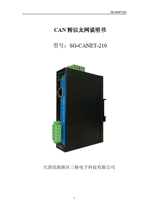
CAN转以太网说明书型号:SG-CANET-210天津滨海新区三格电子科技有限公司一、功能描述SG-CANET-210是一款用来把CAN总线数据转为网口数据的设备。
网口支持TCP Sever、TCP Client、UDP Sever、UDP Client、UDP Broadcast模式,可以通过软件配置和网页配置。
设备提供两路CAN接口,两路CAN可分别配置为不同的工作模式,独立工作,互不影响。
设备可以通过软件配置和网页配置。
网口支持10/100Mbps 自适应以太网接口,支持AUTO-MDIX 网线交叉直连自动切换,支持DHCP功能,支持DNS功能,支持自定义MAC,可自定义心跳包时间,可以跨越网关,可以访问外网。
CAN波特率从5K到500K,支持自定义波特率,支持CAN帧过滤。
可以通过软件和硬件恢复出厂设置。
TCP Sever模式,暂只支持一个Client连接,设备把Client发来的数据发往CAN总线,同时把CAN总线来的数据发给连接成功的客户端。
TCP Client模式下设备自动连接目标(远程)服务器,之后完成CAN总线和目标服务器之间的数据传递。
UDP Sever模式下设备接收所有发往设备IP和端口的数据,并把CAN总线来的数据转发给最近一个发给设备数据的IP和端口。
UDP Client模式下设备完成CAN总线和目标IP端口之间的数据传递。
UDP Broadcast模式下可以实现多台CAN接口设备通过以太网连接。
注意:UDP广播模式适用于多对多的情况,即把多个CAN总线设备通过局域网连接起来,使用UDP广播模式需要设置本地端口和目标端口一样。
二、基本参数与硬件连接2.2 接口说明MB 130.722.080.83电源接口图接线口2.3 使用方法点对点连接两台SG-CANET-210服务器,其中一台作为服务器(SERVER )端,另一台作为客户端(CLIENT )。
客户端的这一台的目的IP 与端口号都需要填写作为服务器端的的IP 地址和端口号。
Christie NAS-S2 用户手册说明书

用户手册
020-101657-01
Christie NAS-S2
用户手册
020-101657-01
声明
版权和商标
版权所有 ©2014 Christie Digital Systems USA Inc. 保留所有权利。
所有品牌名称和产品名称均为其各自所有者的商标、注册商标或商号名称。
或损坏。 e. 因使用从未经授权的科视灯泡、替换部件或组件分销商处购买或获得的任何灯泡、替换部件或组件而引发的问题或造成的损坏,包括
但不限于通过 internet 提供科视灯泡、替换部件或组件的任何分销商 (可向科视确认有哪些经授权的分销商)。 f. 因使用不当、电源不匹配、意外事故、火灾、洪水、闪电、地震或其他自然灾害而引发的问题或造成的损坏。 g.因安装 / 校正不当而引发的问题或造成的损坏,以及由非科视维修人员或非科视授权维修服务供应商进行的设备改装所引发的问题或
天、每天 8 小时。 k. 因在户外使用产品而引发的问题或造成的损坏 (除非产品专用于户外用途),但以下情况除外:保护此类产品免于受到降雨或其他恶
劣天气或环境条件的影响并且室温位于规格中所设定的适合此类产品的推荐室温范围内。 l. LCD 平板上的影像滞留。 m.由正常磨损或产品正常老化造成的缺陷。 保修不适用于序列号已移除或擦除的任何产品。保修也不适用于由转销商出售给转销商所在国家 / 地区之外的最终用户的任何产品,但以 下情况除外:(i) 科视在最终用户所在的国家 / 地区拥有办事处或 (ii) 已支付所需的国际保修费用。
* This part uses metallic alloys, which may contain Lead. - 因该部件使用金属合金材料,故可能含有铅。
电子温度开关系列850用户手册说明书
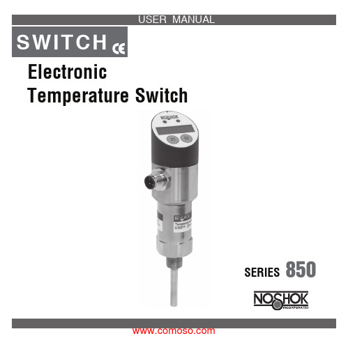
ElectronicTemperature SwitchSERIES850The accepted technical regulations and all national guidelines must always be observed and complied with.CopyrightAll rights to these operating instructions are reserved. These operating instructions, including extracts thereof, must not be copied or translated into other languages without our written permission.Safety Instructions and WarningsPlease read these instructions before installing and starting up the pressure switch. Failure to follow the instructions will make all guarantee, warranty and compensation claims null and void.connection, and the correct tools must always be used. complied with.• Damaged devices must not be started up. If damage occurs during operation, suitablemeasures must be taken to prevent persons or property from being put at risk by the damaged pressure switch.• The switch must only be repaired by NOSHOK.temperaturetemperatureExclusion of LiabilityNOSHOK guarantees that the pressure switch is in perfect working condition when it is delivered. The basis consists of the technical data in the data sheet and these operating instructions. Liability cannot be accepted for the suitability of the pressure switch.Temperature Switch DescriptionThe temperature switch has one analog output and one switching output or two switching out-puts. The switching output(s) is (are) adjusted using the two buttons: set point, reset point (hysteresis), switching function (normally closed/normally open contact).The programmable analog output is a special feature. It can be adjusted in 0.1° steps within a span of at least 20% of the temperature range.Electrical and Mechanical ConnectionThe technical regulations must be complied with during installation and dismantling.The system must be depressurized prior to installation and dismantling.Safety regulations must be complied with, particularly when working on the electrical system. All connections to external electrical equipment must be made in accordance with regulations.The power to system must always be swit tch is being connected.Recommended accessories:M12x1 socket with 2m cable • straight version, order no.: FS-2-4P • angled version, order no.: FA-2-4Pswitching to p potential1 switching output and 1 analog output2 switching outputsSignal ConnectorColors of Optional WiresSupply: +1brown Supply: -3blue Switch output S 14black Switch output S 2 or analog output2whiteRound Connector M 12 x 1 (4-pin)Switching On and OffThe temperature switch is switched on when the supply voltage is applied. There is no on/o switch. A brief initialization phase occurs when the supply voltage is applied to the switch. The display and the set point LED illuminate. The measuring range (min- and max. temperature) and the unit are indicated brie y. The outputs are inactive during this time.After initialization the switch is in normal operating mode. The temperature appears on the display, the switching outputs are active and the LED’s indicate the status of the switching outputs. ProgrammingBrie y pressing button S1 or S2 causes the relevant set point to be displayed.The status LED’s ash for as long as the set points are being displayed.Pressing the buttons for longer (press and hold down button until display ashes) causes the current temperature to be taken over as the set point. The hysteresis remains unchanged. The switching output(s) can be programmed using the control buttons independently from the present temperature, per the programming sequence on page 6.The programming sequence must run without interruptions. If delays of about 20 seconds or more occur, the switch automatically exits programming mode and switches to normal mode. All previous changes are lost.Status-LED Switching Output1 2Parameter description / programmingand for the process pressure 4-digit LED display.1) The pressure units setting applies immediately for the switching point settings, the reset pointsand for the process pressure 4-digit LED display.Technical dataTemperature Ranges-58 to +392°F-58 to +752°F-58 to +1112°F-328 to +1112°FMeasurement Units°C or °F (selectable)Sensor PT100 class B or PT100 class ASupply Voltage12...30 Vdc, overload and reverse polarity protectionripple <10%Power Consumption≤ 50mA, without load currentProcess Connections • Fixed Thread• Compression Fitting 1/2NPT, 1/4NPT1/2NPTOther connections on requestMaterials• Process Connection • Housing Stainless steel 1.4571 (316Ti); other materials or coatings on request Stainless steel, display cover plasticStem and Working Pressure • from stem length (EL) 50mm: ø6 x 0.75mm (up to 40 bar)• from EL 50mm: ø8 x 1.75mm (up to 100 bar)• from EL 50mm: Special parts made of solid material (up to 500 bar) Fast response time version (up to 12 bar)• EL 25mm: ø3 x 0.25mm without taper• EL up to 100mm: ø6 x 0.25mm with taper to ø3 x 0.25mm• from EL 100mm: ø8 x 1.75mm with taper to ø6 x 0.25mm with taper to ø3 x 0.25mmOutputs 2 switching outputs PNP or1 switching output PNP and analog output 4…20mASwitching outputs • Switching function • Switching rating • Adjustment- Set Point- Reset point adjustable normally closed (NC) or normally open (NO) contact100mA per switching outputProgrammable via the display0.1° steps withhin temperature range0.1° steps from beginning temperature range until max. set point –0.1°Analog output SignalLoad resistance 4…20mA; 2-wire, programmable in 0.1° steps,span at least 20% of the temperature rangeDependent on the supply voltage; the relevant formula isAV.0227UR Supply−=Display4-digit 7-segment LED display, red, 7.6mm high Accuracy Switching output, analog output and Display:Accuracy of PT100 + 0,1% of the temperature range Repeatability0.05%Electrical connection M12 x 1 (4-Pin)Temperature range Storage Ambient Thermal E ect -22...+176°F-13...+158°F0.006% of Full Scale/°FEMV to IEC / EN 61 326IEC 61000/4/2 ESD: B IEC 61000/4/3 HF: A IEC 61000/4/4 Burst: A IEC 61000/4/5 Surge: A IEC 61000/4/6 HF: AProtection class IP65 according IEC 529 Weight0.66 lbs.100DIMENSIONS Inches(mm)11CE – ConformityThe switch complies with all requirements of EN 61 326 with regard to interference emission and immunity for use in industrial areas. NOSHOK recommends the use of shielded cables. Installation and cable routing must be carried out correctly in order to maintain the e ective protection from electromagnetic interference.MaintenanceThe temperature switches that are described in this document are maintenance free. The equip-ment will also operate in a stable state for long periods, meaning that regular adjustment or the like is not required.12Remove the device as soon as device malfunctions start to occur. The internals cannot be maintained by the customer. Replace the device or return it to the manufacturer to have it tested.CleaningThe exterior of the 850 Series Temperature Switch can be cleaned using a soft, moistened cloth. Heavy soiling can be removed using a mild cleaning agent.The switch must not be opened for cleaning!Aggressive chemicals or hard scrubbing can damage the surface, particularly the display lm.DisposalThe packaging and used parts must be disposed of in accordance with the regulations of the country in which the device is installed.13Notes:_________________________________________________________ _________________________________________________________ _________________________________________________________ _________________________________________________________ _________________________________________________________ _________________________________________________________ _________________________________________________________ _________________________________________________________ _________________________________________________________ _________________________________________________________ _________________________________________________________ _________________________________________________________ _________________________________________________________ _________________________________________________________ _________________________________________________________141010 West Bagley Road • Berea,Ohio 44017 • 440-243-0888 • FAX 440-243-3472E-MAIL:*****************•WEB:S07。
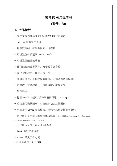
蓝马转换器f2使用说明书5p
*不使用屏蔽滤波功能可以同时接收扩展帧和标准帧。
3.4.5.
通讯速率:最近3秒的平均值。
总线占用率:当前流量与满负荷流量的比率。
图3-6 通讯速率和总线占用率
检测通讯速率尽量使用专用界面,比主界面的更准确。
图3-7 监测总线占空率
3.4.6.
既可以查看某帧数据,又不影响后面的数据接收。
3.2.
打开CAN总线调试软件(4.9或更高版本),选择转换器参数,点击【连接设备】即可。软件操作如下图所示:
图3-1 软件操作图
3.3.
3.4.
选择设备型号为485/422-CAN F2,选择端口COM1(或其他端口),选择CAN通道1参数,然后点击【连接设备】按钮即可。
所有参数需要连接之前选定。如调试中需更改CAN参数,需释放设备并重新连接即可。
-工作电压范围:直流9到 24V
-90mA典型工作电流
-110mA最大工作电流
•工业级温度标准:-40ºC ~ +85ºC
2.
485/422-CAN F2转换器,是具有一路485/422接口和两路CAN接口,可作为一个标准CAN节点,通过PC连接到CAN网络,实现工控现场CAN总线数据的收、发双向传输、CAN中继器等用途。广泛应用于工业控制、安防监控、智能建筑、汽车电子等领域。增加动态链接库,可以进行二次开发。B2型号具有性能稳定,适应宽电压电源输入(9~24V),完善的静电防护和通讯隔离保护。通讯波特率可设定,尤其适用于CAN总线中继,延长通讯距离或波特率变速中继,协议转换等应用。
五种透传方式可选:带命令头的透传、带ID的标准数据帧、带ID的扩展数据帧、不带ID的标准数据帧、 不带ID的扩展数据帧。详细介绍参考第4节《模块工作方式及通讯协议介绍》。
GCAN-202,Ethernet转CAN用户手册

GCAN-202工业级以太网-CAN转换器用户手册文档版本:V3.52 (2017/09/30)目录1. 功能简介 (4)1.1 功能概述 (4)1.2 性能特点 (4)1.3 典型应用 (5)2. 设备安装 (6)2.1 安装固定 (6)2.2软件安装 (6)2.3 与PC连接 (6)2.4 与CAN总线连接 (6)3. 设备使用 (7)3.1 与PC连接进行配置 (7)3.2 与以太网连接 (7)3.3 与CAN连接 (8)3.4 CAN总线终端电阻 (9)3.5 系统状态指示灯 (9)4. CANet Config软件使用 (11)4.1 恢复出厂设置 (11)4.2 GCAN-202连接 (11)4.3 配置通讯基本信息 (11)4.4 配置完成 (12)4.5 保存/加载配置文件 (12)4.6 升级CANet固件内核(此功能请在指导下使用) (12)5. CANet简易测试软件使用 (14)6. 网络调试助手使用方法 (15)6.1 调试前准备工作 (15)6.2 TCP Server模式通信测试 (16)6.3 TCP Client模式通信测试 (17)6.4 UDP模式通信测试 (18)6.5 CAN口状态的TCP通知数据格式说明 (19)7.GCAN-202在线修改波特率功能 (20)7.1 功能说明 (20)7.2 格式说明 (20)7.3 发送举例 (20)8. 二次开发 (21)9. 技术规格 (22)10. 常见问题 (23)附录A:CAN2.0B协议帧格式 (24)附录B:GCAN-202(CANet)数据流定义 (26)1. 功能简介1.1 功能概述广成科技GCAN-202(CANET-II)是集成2路CAN接口、1路以太网接口的高性能型CAN-bus总线通讯接口卡。
采用GCAN-202高性能CAN接口卡,用户可以轻松完成CAN-bus 网络和以太网网络的互连互通,进一步拓展CAN-bus 网络的范围。
太阳网路CP32x0四个GbE双路光纤通道高级后端转换模块用户指南说明书

This document provides documentation links,safety information,technical support,and customer suggestion information for Oracle’s Sun Netra CP32x0Quad GbE,Dual-Fibre Channel,Advanced Rear Transition Module.Where to Find Documentation■For installation instructions and technical details,refer to the Sun Netra CP32x0Quad GbE,Dual-Fibre Channel,Advanced Rear Transition Module User’s Guide (820-3148).■For software and firmware installation and upgrade instructions,refer to the Sun Netra CP32x0Advanced Rear Transition Module Product Notes (820-3261).You can find these documents and safety documents at:/app/docs/prod/cp32x0.4gbefc?l=en#hic Safety ConsiderationsFor general safety information,refer to Important Safety Information for Sun Hardware Systems (821-1590),which shipped with the advanced rear transition module (ARTM).For product specific safety information,refer to the Sun Netra CP32x0Advanced Rear Transition Module Safety and Compliance Guide (820-3506).Contacting Technical SupportIf you have technical questions about this product that are not answered in this document,go to:/service/contactingWhen you call,tell them that the product was purchased separately and is not associated with a system.Have the product identification information ready when you call.You can find the part number,serial number,and revision level on labels on the product.If possible,have the product in front of you when you contact TS.When Returning a ComponentYou must get Return Material Authorization (RMA)numbers from TS or the World Wide Solution Center for each component you intend to return.Ensure that these RMA numbers are on the boxes containing the returned components.If TS asks for a system serial number,be sure to indicate that the product was purchased separately and is not associated with a system.TS will give you specific details on the return procedure for your geographic area.Remove any installed advanced mezzanine card (AMC),peripheral mezzanine card (PMC),or PMC I/O modules (PIMs)before returning the product.Refer to the Sun Netra CP32x0Quad GbE,Dual-Fibre Channel,Advanced Rear Transition Module User’s Guide (820-3148)or the third-party vendor’s documentation for removal instructions.Sun Netra CP32x0 Quad GbE Dual-Fibre Channel, Advanced Rear Transition ModuleStart HereProduct DocumentationYou can view,print,or purchase a broad selection of documentation,including localized versions,at:Documentation FeedbackSubmit comments about this document by clicking the Feedback[+]link at.Include the title and part number of your document with your feedback:Sun Netra CP32x0Quad GbE,Dual-Fibre Channel,Advanced Rear Transition Module Start Here, part number820-3149-11Copyright©2009,2010Oracle and/or its affiliates.All rights reserved.Copyright©2009,2010Oracle et/ou ses affiliés.Tous droits réservés.Part No. 820-3149-11, Rev. AMay 2010。
02-登录交换机操作
CANSwitch-AF2S2与CANHub-AF2S2的区别与特色
CANSwitch-AF2S2与CANHub-AF2S2的区别与特色摘要:要实现改变CAN网络拓扑结构、延长网络通讯距离、增加节点数目、抗干扰等功能,CAN光纤转换器一定是您的不二选择,可是同为两路CAN和两路光纤接口的Hub 与Switch转换器有哪些区别与特色呢?CAN 网络的传输介质可以是双绞线、光纤和同轴电缆。
目前,双绞线的CAN 总线分布式系统已得到了广泛应用,如汽车、电梯控制、电力系统控制等,各项技术已经成熟。
与双绞线和同轴电缆相比,光纤的低传输损耗使传输距离大大增加。
除此以外,光缆还具有不辐射能量、不导电、没有电感等特性,且光缆中不存在串扰以及光信号相互干扰的影响,具有优良的抗EMI 以及EMC 特性,也不会有在线路感应耦合导致的安全问题。
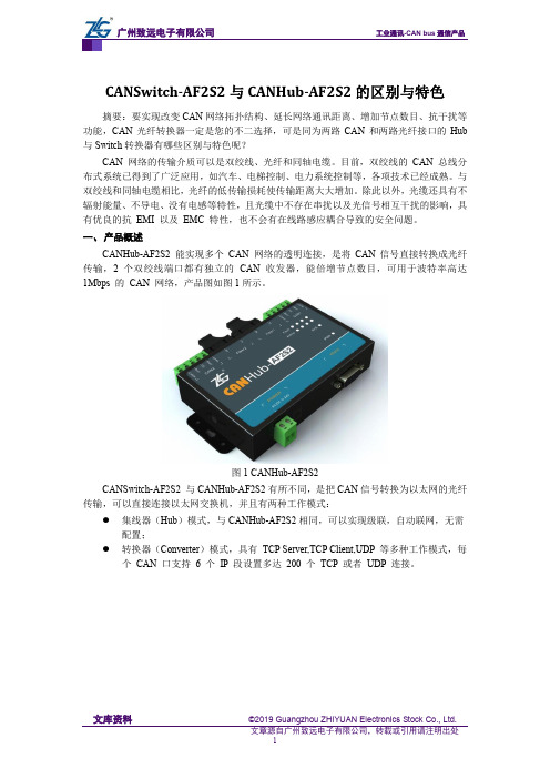
一、产品概述CANHub-AF2S2 能实现多个CAN 网络的透明连接,是将CAN信号直接转换成光纤传输,2 个双绞线端口都有独立的CAN 收发器,能倍增节点数目,可用于波特率高达1Mbps 的CAN 网络,产品图如图1所示。
图1 CANHub-AF2S2CANSwitch-AF2S2 与CANHub-AF2S2有所不同,是把CAN信号转换为以太网的光纤传输,可以直接连接以太网交换机,并且有两种工作模式:●集线器(Hub)模式,与CANHub-AF2S2相同,可以实现级联,自动联网,无需配置;●转换器(Converter)模式,具有TCP Server,TCP Client,UDP 等多种工作模式,每个CAN 口支持 6 个IP 段设置多达200 个TCP 或者UDP 连接。
图2 CANSwitch-AF2S2二、产品详细参数对比1. 区别2. 相同点CAN接口●CAN 口数目:2;●接口类型:采用OPEN 接口方式,2.5KV 电磁隔离;●信号线:CAN0H、CAN0L、CAN1H、CAN1L;●屏蔽线:FGND;●终端电阻:内置式120 欧终端电阻,连接R+和R-端子;●波特率:5Kbps~1000Kbps。
ICAN-2快速安装指南
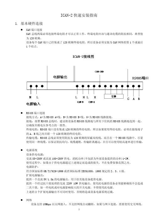
ICAN-2快速安装指南1. 基本硬件连接CAN端口连接CAN总线两端必须连接终端电阻才可以正常工作,终端电阻应该与通讯电缆的阻抗相同,典型值为120欧姆。
设备每个CAN端口已经集成了120欧姆终端电阻,所以设备必须安装为CAN网络的第1个或最后1个结点。
RS485端口连接接线方式:A-为RS485 A+线,B-为RS485 B-线,G-为RS485线路接地。
接地:部署RS485总线时,建议将设备的RS485线路地与所有下位机的RS485线路地连到一起,以确保共模电压参考点的一致性。
终端电阻:RS485端口没有集成120欧姆的终结电阻,所以如果使用终结电阻,必须在接线端子的A、B线之间并联一个120欧姆的终结电阻。
传输电缆:RS485总线必须使用阻抗为120欧姆的屏蔽双绞线,而且在一个RS485线路中,尽量使用同一种线缆,以保证阻抗均匀。
线缆越粗,传输距离越远,并且可以使用较高速率进行传输。
电源系统设备供电电源:交流85-250V或直流100-250V供电,消耗功率(不包括为外部设备提供的功率)1-2W。
使用过程中,如果由于供电电源超过上述规定而造成的损失,不在免费保修范围之内。
电源防护:符合国家标准GB/T17626-1999或者国际标准IEC61000:1995规定的2、3、4级。
扩展电源输出:提供一个直流5V/1.5A的电源输出,用于给其他设备提供电源。
提供一个经过抗干扰处理的交流220V 10W供电输出,使用此电源的设备必须能够确保不会造成二次干扰,如一些电机或对电源影响较大的开关电源,不得使用此电源。
上述的2个扩展电源输出不可同时使用,否则将造成设备电源系统过载。
网络设备支持10Mbps以太网接入,不支持网线自动翻转,如果与网卡连接,需要使用交叉网线。
与交换机或集线器连接,使用普通的568B/A网线即可。
在使用光收发器接入光网络时,可以使用设备提供的直流5V来提供电源。
2. 检查运行状态指示灯上电后就可以观察设备的工作状态。
CANET-I II CAN 转以太网适配器说明书

CANET-I/II CAN转以太网适配器使用说明书 (创新的高速智能CAN接口卡)版本:V2.0目 录目 录 (2)第一章 产品简介 (3)1.1 产品概述 (3)1.2 性能指标 (3)1.3 应用领域 (3)1.4 订购信息 (3)1.5 产品销售清单 (4)1.6 技术支持与服务 (4)第二章 硬件连接 (5)2.1 硬件接口描述 (5)2.2 系统连接 (5)2.3 总线终端电阻 (6)第三章 参数设置 (7)3.1 PC 机与模块网段检测 (7)3.2 Windows98/Me 网络设置 (7)3.3 Windows2000 网络设置 (7)3.3.1 增加本机IP 地址 (7)3.3.2 修改本机IP 地址 (9)3.4 配置软件CANET-I/II Config (10)3.4.1 软件操作 (10)3.2.2 设备参数描述 (11)3.4 测试软件CANET-I/II Tester (12)第四章 通信转换规约 (13)4.1 转换格式规约 (13)4.2 软件编程示例 (14)光盘中附带VC,BC例程源代码。
(14)附录 (15)第一章 产品简介1.1 产品概述CANET-I/CANET-II 高性能CAN转以太网适配器,集成了一路CAN-bus 接口(CANET-I)或两路CAN-bus 接口(CANET-II)和EtherNet 接口以及TCP/IP 协议栈,用户利于它可以轻松完成CAN-bus 网络和EtherNet 网络的互连互通,进一步拓展CAN-bus 网络的范围。
CANET-I/II CAN转以太网适配器每路CAN通道都集成完全的电气隔离保护、防浪涌保护,抗干扰能力强,是一款性能稳定、通讯可靠的CAN以太网转换器。
CANET-I/II适配器的转换效率达到CAN的理论极限为6500帧/S(1Mbps扩展帧下测的),适合CAN 的低速到高速的所有应用。
1.2 性能指标♦32位ARM9处理器,内嵌实时操作系统;♦流量6500帧/S(1Mbps下扩展帧,远超同类产品包括ZLG CANET-100T CANET-200T);♦采用实时操作系统配合自适应流量控制算法,适合对实时性要求苛刻的控制系统使用。
SC-ISOCON-6用户手册说明书

SC-ISOCON-6 USERS GUIDESC-ISOCON-624V AC or DC POWEREDISOLATING SIGNAL CONVERTERWhilst every effort has been taken to ensure the accuracy of this document, we accept no responsibility for damage, injury, loss or expense resulting from errors or omissions, and reserve the right of amendment without notice.Cynergy3 Components LtdThis document may not be reproduced in any way without the prior writtenpermission of the company.July 2017SC-ISOCON-6 USERS GUIDECONTENTS1. INTRODUCTION ____________________________________ 3 1.1 Hardware Features _________________________________ 31.1.1 Isolation Details __________________________________ 32. UNPACKING ________________________________________ 33. CONNECTIONS _____________________________________ 44. CONFIGURING THE ISOCON _________________________ 5 4.1.1 Voltage Input: ___________________________________ 6 4.1.2 Current Input ____________________________________ 7 4.1.3 Millivolt (mV) Input ______________________________ 8 4.1.4 Potentiometer Input _______________________________ 9 4.1.5 Thermocouple Input ______________________________ 10 4.1.6 RTD Input _____________________________________ 114.1.7 Output Configuration _____________________________ 125. CALIBRATING THE ISOCON ________________________ 136. INSTALLATION ____________________________________ 147. TROUBLESHOOTING _______________________________ 15 7.1 Incorrect Reading _________________________________ 157.2 Sensor Failure ____________________________________ 158. SPECIFICATIONS ( @ 25°C) _________________________ 16Cynergy3 Components Ltd, Ferndown Industrial Estate,Wimborne, Dorset, BH17 9FE, UKTel: 01202 897969, Fax: 01202 891918******************SC-ISOCON-6 USERS GUIDE1.INTRODUCTION1.1Hardware FeaturesThe SC-ISOCON-6 is a universal input Isolating Signal Converter. It can accept virtually every type of analogue input signal from millivolts to 40Vdc, mA, thermocouples, RTD’s etc. It also produces 3 types of analogue output; voltage, mA source, or mA sink.The unit can be powered by any DC voltage between 12 and 36Vdc or 12 and 32Vac. For mains AC voltage the SC-ISOCON-3 is available which can be powered from any supply from 90Vac to 264Vac at 50 or 60Hz.The instrument is packaged in a very compact 12.5mm wide enclosure which can be mounted on standard TS35 DIN-rail.The unit can also be equipped with 1 digital output which can be either a relay or an open collector output, or a second analogue output (see DUALCON-6). Note, units with above options are housed in a 17.5mm wide box.1.1.1Isolation DetailsThe SC-ISOCON-6 has full 3 port isolation of 1000V between the Input Stage, Output Stage and Power Supply for functional reasons.2.UNPACKINGThe instrument should be carefully inspected for signs of damage which may have occurred in transit. In the unlikely case that damage has been sustained, DO NOT use the instrument, but please retain all packaging for our inspection and contact your supplier immediately.The instrument comes with the following items as standard:1 SC-ISOCON-6 Isolating Signal Converter1SC-ISOCON-6 User GuideIf the instrument has been factory configured the input and output details will be listed on the Serial number label on the side of the unit. If this label is blank then the unit will be set to its default configuration which is 4-20mA input and 4-20mA source output. Please check that the details on the side label are correct, especially the power supply voltage.If re-configuration is required please refer to Section 4 of this manual.SC-ISOCON-6 USERS GUIDE 3.CONNECTIONSThe ISOCON is housed in a compact DIN rail mounting enclosure, with 8 terminals, arranged in 4 rows of 2 terminals. Two rows are at the top of the front panel and 2 rows are at the bottom. All the sensor input terminals are on the bottom rows and the power supply and analogue outputs are on the top terminals.The diagram below shows how to connect all the different input, output and power supply types.12-36Vdc / 12-32Vac0V3 Wire RTD4 Wire RTD125R to 1K2 Wire Pot1K to 100K3 Wire Pot 21SC-ISOCON-6 USERS GUIDE4. CONFIGURING THE ISOCONThe ISOCON is an extremely versatile device which can support many different types of input. The unit is configured by turning the power off, selecting the internal switch settings required and turning the power back on.To open the Isocon, 2 catches just below the outer terminal blocks must be pushed in gently, one at a time. The front of the case can then be pulled and the unit will come out of the box.There are 3 switch banks, S1, S2, and S3, located inside the ISOCON as shown below:Switch S1 and S2 configure the input type and range, and switch S3 configures the output type, range and a few additional functions. The switch settings are explained in the next few pages. The diagrams refer to switch positions 0 and 1, with 0 being OFF and 1 being ON. This is illustrated in the picture above.SC-ISOCON-6 USERS GUIDE 4.1.1Voltage Input:Select the range from the table below and set Switch S1 to the required values.Then select the required setting from the table below for switch S2Please note that PC Software is available to provide information onswitch settings for your input and output requirements.SC-ISOCON-6 USERS GUIDE4.1.2Current InputSelect the range from the table below and set Switch S1 to the required values.Then select the required setting from the table below for switch S2Please note that PC Software is available to provide information on switch settings for your input and output requirements.SC-ISOCON-6 USERS GUIDE 4.1.3Millivolt (mV) InputSelect the range from the table below and set Switch S1 to the required values.And then select the required setting from the table below for switch S2Please note that PC Software is available to provide information on switch settings for your input and output requirements.SC-ISOCON-6 USERS GUIDE4.1.4Potentiometer InputSelect the range from the table below and set Switch S1 to the required values.Then select the required setting from the table below for switch S2Please note that PC Software is available to provide information on switch settings for your input and output requirements.SC-ISOCON-6 USERS GUIDE4.1.5 Thermocouple InputSelect the range from the table below and set Switch S1 to the required values.Then select the required setting from the table below for switch S2Please note that PC Software is available to provide information onswitch settings for your input and output requirements.4.1.6RTD InputSelect the range from the table below and set Switch S1 to the required values.And then select the required setting from the table below for switch S2Please note that PC Software is available to provide information on switch settings for your input and output requirements.4.1.7Output ConfigurationSelect the range from the table below and set Switch S3 to the required values.Examples:Please note that PC Software is available to provide information on switch settings for your input and output requirements.5. CALIBRATING THE ISOCONWhen the unit is shipped the ISOCON will be calibrated for the input and output types and ranges noted on the side label. If this label is blank then the unit will be calibrated for 4-20mA input and 4-20mA source output.If the unit is re-ranged by the user it is necessary to re-calibrate the unit to obtain the maximum accuracy. The calibration is achieved by using both switches on the front panel to select the zero or span input and then using the switches as raise/lower buttons to adjust the output to the value required.The mode the unit is in is indicated by the colour of the LED: Green - Normal Operation Red - Span Adjust Yellow - Zero AdjustSetting of the zero and span points is non-interactive, so each point need only be set once. A typical calibration sequence would be as follows:LED Colour Mode ActionGreen Normal Apply full scale input.Press and release both buttons together to enterspan modeRED Span Adjust Press raise / lower buttons to adjust output valuePress and release both buttons together to returnto normal modeGreen Normal Apply zero scale inputPress and release both buttons together to enterzero modeYELLOW Zero Adjust Press raise / lower buttons to adjust output valuePress and release both buttons together to returnto normal modeGreen Normal Use productThe unit is now calibrated and ready for use.Note: The unit will retain the new settings on power down.When the unit is used to convert a thermocouple input it is important when calibrating to ensure that the thermocouple simulator employed is switched to automatic cold junction compensation and is at the same ambient temperature as the ISOCON. Note that this is not always easy to achieve, especially if the ISOCON is mounted in a warm cabinet. An altenative method is to use an ice-point reference and a mV source.6.INSTALLATIONThe ISOCON’s input and output circuits are classed as Separated Extra Low Voltage (SELV). This means that they must not be externally connected to voltages exceeding 30V ac or 60V dc, nor do they generate voltages above these limits internally. Where a higher voltage input is required a specially designed DIVIDER unit can be used to condition the input signal prior to connection to the process input terminals.The ISOCON unit clips directly onto ‘Top Hat’ (TS35) symmetrical DIN rail. Ideally, mounting orientation should be vertical, with the power supply situated on the top face to minimise temperature rise. Good airflow around the unit will maximise reliability of the instrument.The use of bootlace ferrules is recommended on wiring terminations.Do not exceed terminal torque rating of 0.4 Nm – use an appropriate screwdriver. The unit can be removed from the DIN rail by sliding a small screwdriver into the slot at the rear of the enclosure on the lower face and gently levering the metal clip, whilst lifting the unit from the rail.7.TROUBLESHOOTINGThe ISOCON has some built in self diagnostic functions. If the LED on the front panel is flashing then the fault mode can be found by counting the number of flashes between gaps and using the table below to locate the problem.No ofFlashesNature of Fault Corrective Action0 (Green On) Unit Working – no suspectedfaultCheck Wiring and switchsettings2,3,4,5,6,8,9, 10,11,12Green Hardware Error, extremenoise, poor supplySwitch off unit, check switchsettings, and wiring, and retry.If still faulty please contactsupplier7Green RTD / ThermocoupleburnoutRepair RTD, T/C or wiring3 or4 Red Span point is too close tozero point Change input span value and retry3 or4 Yellow Zero point is too close tospan pointChange input zero value andretryNo LED Power Failure Check supply lines and voltage 7.1Incorrect Reading∙Check that Unit is configured for the correct Sensor∙Check that Input Scaling is as required.∙Check that Linearisation has not been set incorrectly.∙Check that Thermocouples have correct compensation cables, and polarity. ∙Check that RTD is set for correct option 2, 3 or 4 Wire.∙Check that RTD leads are connected to appropriate terminal pins.7.2Sensor Failure∙Check that sensor wiring is correct.∙Check Thermocouple polarity.∙Check that all RTD leads are connected to correct terminals.∙Check that the ISOCON is configured for correct sensor.∙Check that applied voltage is not out of range.∙Check that applied current is not out of range.∙Check that applied millivoltage is out of range.8. SPECIFICATIONS ( @ 25°C)Operating Temperature 0 to 55 °COperating Altitude Sea Level to 2000mRH Humidity 0-90% RequirementsPowerDC Supply 12 to 36VdcAC Supply 12 to 32VacCurrent Consumption 55mA @ 24Vdc (20mA in & out)85mA@24Vdc(maximum load, tx supply)200mA@12Vdc(maximum load, tx supply)260mA for 50ms on 24Vdc power up Transmitter Power Supply 22V to 29V @ up to 24mADependant on supply voltage and load Calibration accuracy ±0.05% full scaleLinearity ±0.05% full scaleTemperature Stability 50ppm / °CInput Impedance:Current Input 15 ohmsVoltage Input 1 MohmMillivolt Input Greater Than 10 MohmThermocouple Burn Out Current: 500nA NominalCold junction compensation accuracy ±0.5°C over operating rangeMaximum Voltage Output 11.5 V into a minimum of 7Kohm Maximum Current Output 23.0 mA into a maximum of 1KohmTime Response (90% of step change): 50ms ± 10msUnit has full 3 port Isolation to 1kV between Power Supply, Input and Output.The unit can also withstand transients of 2.5kV for 50 µsecs.Dimensions 114.5 mm x 99mm x 12.5mm (H x D x W) Mounting DIN Rail TS35Connections Screw Clamp with pressure plate Conductor Size 0.5 to 4.0 mmInsulation Stripping 12 mmMaximum Terminal Torque 0.4 Nm95g Weight Approx.EN61326 EMC BSLVD Standards EN61010-1Installation Category (IEC 664) IIPollution Degree (EN61010-1) 2Equipment Class (IEC 536) II。
rB-R2S2模块产品说明书

Information about the rB–R2S2 moduleUseThe rB-R2S2 module is a transmitter modu-le used to control any two electrical circuits connected to it, or for the connection ofa double momentary switch.It is dedicated for electrical sockets, lightbulbs etc.More information at .OperationThe module allows the connected deviceto be controlled via a smartphone as well as a traditional switch.The Proxi application can be downloaded for free from Google Play and the App Store and it runs on any smartphone equipped with Bluetooth 4.0 and iOS or Androidversion 4.3 or above.Connection schematicInstallation1. Disconnect the power circuit and using an appropriate device, check that the circuit is not powered.2. Connect the switch wires to the S1 and S2 contacts.3. Connect the socket wires to theappropriate module contacts as shown on the diagram. 4. Connect the live and neutral wires to the appropriate L and N contacts.5. Insert the module into the junction box. 6. Connect the power supply. If the module has been installed correctly, the blue diode on the module should blink.S1S2- switch no. 1- switch no. 2- live wireAC 230 V / 50 Hz -20%, +10%1 W bluetooth 2,4 GHz 1 mW two directional yes 22x 4 A / AC 250 V triggered by the L or N level 2x contact <= 1 mA -20°C, +50°C 0°C, +45°C <= 85% (without water vapour condensation and corrosive gases)49 x 44 x 22 mm IP 20junction box yes yes rated powervoltage rangerated power consumptionradio connectionsignal strengthtransmission typeencodingnumber of relaysreceiversinputcontrolling currentstorage temperatureoperating temperaturehumiditydimensionsprotection codetype of housingoverheating protectionautonomus modeTechnical data9083125973605Warranty F&F products are guaranteed for 24 months from the date of purchase.F&F Filipowski sp. j. ul. Konstantynowska 79/81, 09-200 Pabianice POLANDtel./fax+**********************.pl,.pl©2014 F&F Filipowski sp. j. All rights reserved.。
S-2CONNECT Sense用户手册说明书
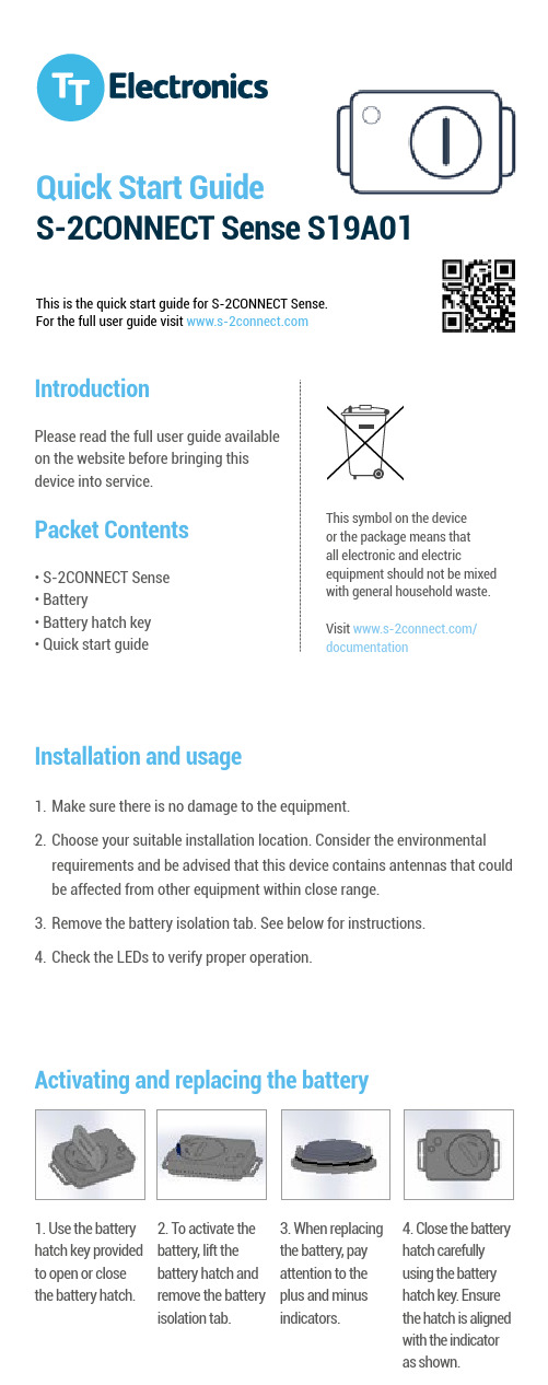
IntroductionPlease read the full user guide available on the website before bringing this device into service.Packet Contents• S-2CONNECT Sense • Battery• Battery hatch key • Quick start guideThis symbol on the device or the package means that all electronic and electricequipment should not be mixed with general household waste. Visit /documentation1. Use the battery hatch key provided to open or close the battery hatch.2. To activate the battery, lift the battery hatch and remove the battery isolation tab.3. When replacing the battery, pay attention to the plus and minus indicators.4. Close the battery hatch carefully using the battery hatch key. Ensure the hatch is aligned with the indicator as shown.Activating and replacing the batteryInstallation and usage1. Make sure there is no damage to the equipment.2. Choose your suitable installation location. Consider the environmental requirements and be advised that this device contains antennas that could be affected from other equipment within close range.3. Remove the battery isolation tab. See below for instructions.4. Check the LEDs to verify proper operation.Quick Start GuideS-2CONNECT Sense S19A01This is the quick start guide for S-2CONNECT Sense.For the full user guide visitRadio frequenciesS-2CONNECT Sense must be used in compliance with applicable and international regulations that restrict utilisation of radio communication modules. Refer to the fullS-2CONNECT Sense user guide for more information.The full user guide can be downloaded from /documentationDeclaration of ConformityTT Electronics hereby declares that S-2CONNECT Sense complies with the essential requirements of the EU directive RED2014/53/EU Full details available at: /documentationFCCComplianceS-2CONNECT Sense has been tested to fulfil FCC requirements. Test reports are available upon request.Switching the device onThis device switches onautomatically following insertion of the battery.Using the deviceThis device is intended for strictly remote operation. Log in to your user interface to interact with the device.LED functionalityThe LED in S-2CONNECT Sense operates as follows:• Long Blink at battery insertion • Short Blink when communicating with S-2CONNECT Hub。
NS2教学手册
NS2 教學手冊( NS2 Learning Guide)[My works]●●Installation。
(windows + cygwin + ns-2.27) 中文English Video(cygwin + myNS2)。
(請不要再參考中文版的安裝說明,因為若是目前使用網路下載安裝cygwin的方式,會使得ns2無法成功的安裝) (找不到ns的解決辦法)●●TCL Introduction。
中文English。
●●Tool Introudction。
(Use awk to analyze the trace file to get throughput, delay, jitter, andloss rate. Then use gnuplot to plot the data.) 中文English。
●●Add or Modify NS2 module。
中文English。
●●Multimedia Communication。
1. 1.English(par1:Traffic Trace)2. 2.English(part2:Enhanced Evalvid)3. 3.English(part3:H.264)4. 4.English(part4: An example of multimedia transmission over a wireless network)(co-operated with Cheng-Han Lin)5. 5.English(part5:MDC)6. 6.English 6 (H.263/H.264/MPEG4)。
7.7.Video transmission over wireless error channels。
8.8.myEvalvid-NT9.9.How to adaptively adjust FEC to improve the delivered video qaulity over erroneouswireless channels? (co-operated with Cheng-Han Lin)●●TCP parameters Description。
- 1、下载文档前请自行甄别文档内容的完整性,平台不提供额外的编辑、内容补充、找答案等附加服务。
- 2、"仅部分预览"的文档,不可在线预览部分如存在完整性等问题,可反馈申请退款(可完整预览的文档不适用该条件!)。
- 3、如文档侵犯您的权益,请联系客服反馈,我们会尽快为您处理(人工客服工作时间:9:00-18:30)。
摘要
广州致远电子股份有限公司
广州致远电子股份有限公司
CANSwitch-AN2S2 用户手册
高性能双路 CAN 转以太网交换机用户手册
修订历史
版本 V1.00 日期 2015/12/06 原因 创建文档
产品用户手册
©2015Guangzhou ZHIYUAN Electronics Stock Co., Ltd. i
设备配置方法 ............................................................................................................. 19 4.1.1 使用串口配置设备 ......................................................................................... 19 4.1.2 使用网口配置设备 ......................................................................................... 19 4.2 关于 IP 地址操作 ....................................................................................................... 19 4.2.1 设备 IP 出厂设置 ........................................................................................... 19 4.2.2 用户获取设备 IP ............................................................................................ 19 4.2.3 PC 机与设备网段检测 ....................................................................................... 20 4.2.4 增加本机 IP 地址(以 Windows7 操作系统为例) .................................... 21 4.2.5 修改本机 IP 地址 ........................................................................................... 23 4.3 TCP Server 模式 ......................................................................................................... 24 4.3.1 系统框图 ......................................................................................................... 24 产品用户手册
广州致远电子股份有限公司
CANSwitch-AN2S2 用户手册
高性能双路 CAN 转以太网交换机用户手册
目录
1. 功能简介................................................................................................................... 1
1.1 概述............................................................................................................................... 1 1.1.1 强大的硬件 ....................................................................................................... 2 1.1.2 完善的功能 ....................................................................................................... 2 1.2 产品规范 ....................................................................................................................... 3 1.2.1 LAN ...................................................................................................................... 3 1.2.2 CAN ...................................................................................................................... 3 1.2.3 电源接口 ........................................................................................................... 3 1.2.4 配置接口 ........................................................................................................... 3 1.2.5 软件特性 ........................................................................................................... 3 1.2.6 EMC 特性 ............................................................................................................. 3 1.2.7 电气参数 ........................................................................................................... 4 1.3 机械尺寸 ....................................................................................................................... 5
2. 产品硬件接口说明................................................................................................... 6
2.1 2.2 2.3 2.4 2.5 2.6 2.7 3.1 外观图 ........................................................................................................................... 6 电源接口 ....................................................................................................................... 7 RS232 配置接口 ........................................................................................................... 7 复位按钮、恢复出厂设置按钮及功能转换开关 ....................................................... 7 以太网接口 ................................................................................................................... 7 CAN 口 ......................................................................................................................... 8 LED 指示灯 .................................................................................................................. 9 设备配置方法 ............................................................................................................. 10 3.1.1 使用串口配置设备 ......................................................................................... 10 3.1.2 使用网口配置设备 ......................................................................................... 10 系统框图 ..................................................................................................................... 10 配置设备 ..................................................................................................................... 11 CANTest 软件操作 ..................................................................................................... 14 测试结果 ..................................................................................................................... 16
