2011 美赛 数模 B题资料
2011年数学建模论文 B 题

承诺书我们仔细阅读了中国大学生数学建模竞赛的竞赛规则.我们完全明白,在竞赛开始后参赛队员不能以任何方式(包括电话、电子邮件、网上咨询等)与队外的任何人(包括指导教师)研究、讨论与赛题有关的问题。
我们知道,抄袭别人的成果是违反竞赛规则的, 如果引用别人的成果或其他公开的资料(包括网上查到的资料),必须按照规定的参考文献的表述方式在正文引用处和参考文献中明确列出。
我们郑重承诺,严格遵守竞赛规则,以保证竞赛的公正、公平性。
如有违反竞赛规则的行为,我们将受到严肃处理。
我们参赛选择的题号是(从A/B/C/D中选择一项填写): B我们的参赛报名号为(如果赛区设置报名号的话):所属学校(请填写完整的全名):四川文理学院参赛队员(打印并签名) :1. 高陆2. 肖皓华3. 吕洋琴指导教师或指导教师组负责人(打印并签名):李爱民日期: 2011 年 9 月 12 日赛区评阅编号(由赛区组委会评阅前进行编号):编号专用页赛区评阅编号(由赛区组委会评阅前进行编号):赛区评阅记录(可供赛区评阅时使用):评阅人评分备注全国统一编号(由赛区组委会送交全国前编号):全国评阅编号(由全国组委会评阅前进行编号):关于交巡警服务平台设置与调度的优化模型摘要本文旨在研究交巡警服务平台的设置与调度问题,根据不同的问题分别建立了与之相应的数学模型。
问题一以中心城区A为主要研究范围,而问题二则主要研究全市(主城六区A,B,C,D,E,F)交巡警服务平台的设置与调度问题。
为解决问题一的三个子问题,我们在认真研究该城区交通网络及现有的20个交巡警服务平台设置情况的基础上,利用题中所给附件2中列出的关于城区A的92个节点的横纵坐标这一具体数据,得出了各个节点间的距离(程序实现见附录2)。
针对问题一的子问题一,即为城区A的各交巡警服务平台分配管辖范围,因要考虑到当在其管辖范围内出现突发事件时,该服务平台的交巡警能尽量在3分钟内到达事发地。
而在此3分钟内,警车所经过的路程不超过3km(警车时速为60km/h)。
2011数学建模B题编程最优路径
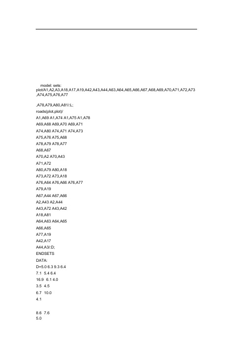
model: sets:plot/A1,A2,A3,A18,A17,A19,A42,A43,A44,A63,A64,A65,A66,A67,A68,A69,A70,A71,A72,A73 ,A74,A75,A76,A77,A78,A79,A80,A81/:L;roads(plot,plot)/A1,A69 A1,A74 A1,A75 A1,A78A69,A68 A69,A70 A69,A71A74,A80 A74,A71 A74,A73A75,A76 A75,A68A78,A79 A78,A77A68,A67A70,A2 A70,A43A71,A72A80,A79 A80,A18A73,A72 A73,A18A76,A64 A76,A66 A76,A77A79,A19A67,A44 A67,A66A2,A43 A2,A44A43,A72 A43,A42A18,A81A64,A63 A64,A65A66,A65A77,A19A42,A17A44,A3/:D;ENDSETSDATA:D=5.0 6.3 9.3 6.47.1 5.4 6.416.9 6.1 4.03.54.56.7 10.04.18.6 7.65.04.5 8.18.1 19.713.2 9.2 4.54.514.8 4.28.0 9.58.1 8.16.79.1 5.83.29.89.89.5;L=0,,,,,,,,,,,,,,,,,,,,,,,,,,,;ENDDATA@for(plot(i)|i#GT#@index(A1): L(i)=@MIN(roads(j,i):L(j)+D(j,i));); end model: sets:plot/A2,A1,A3,A17,A41,A42,A43,A44,A64,A65,A67,A68,A69,A70,A71,A72,A73,A74,A75,A76 ,A78/:L;roads(plot,plot)/A2,A44 A2,A43 A2,A70A44,A67 A44,A3A43,A72 A43,A70 A43,A42A70,A69A67,A68A3,A65A72,A73 A72,A71A42,A17A69,A71 A69,A68 A69,A1A68,A75A65,A64A73,A74A71,A74A17,A41A1,A75 A1,A78 A1,A74A75,A76A64,A76/:D;ENDSETSDATA:D=9.5 8 8.614.8 11.68.1 7.6 8.15.44.115.28.1 58.56.47.1 54.55.84.06.18.59.3 6.4 6.33.513.2;L=0,,,,,,,,,,,,,,,,,,,,;J v 5 5 5 5 5 5 5 5 5 5 5 5 5 5 5 5 5 5 5 5 JENDDATA@for(plot(i)|i#GT#@index(A2): L(i)=@MIN(roads(j,i):L(j)+D(j,i));); endA3model: sets: plot/A3,A2,A4,A38,A39,A40,A43,A44,A64,A65,A66,A67,A68,A69,A70,A75/:L; roads(plot,plot)/A3,A65 A3,A44A65,A66 A65,A64A44,A2 A44,A67A66,A67A2,A40 A2,A43 A2,A70A67,A68A40,A39A43,A70A70,A69A68,A69 A68,A75A39,A4 A39,A38/:D;ENDSETSDATA:D=15.2 11.63.2 5.89.5 14.84.219.1 8 8.64.117.77.65.47.1 4.545.6 3;L=0,,,,,,,,,,,,,,,;J v 5 5 5 5 5 5 5 5 5 5 5 5 5 5 5 JENDDATA @for(plot(i)|i#GT#@index(A3): L(i)=@MIN(roads(j,i):L(j)+D(j,i));); endmodel: sets:plot/A1,A2,A3,A18,A17,A19,A42,A43,A44,A63,A64,A65,A66,A67,A68,A69,A70,A71,A72,A73 ,A74,A75,A76,A77,A78,A79,A80,A81/:L;roads(plot,plot)/A1,A69 A1,A74 A1,A75 A1,A78A69,A68 A69,A70 A69,A71A74,A80 A74,A71 A74,A73A75,A76 A75,A68A78,A79 A78,A77A68,A67A70,A2 A70,A43A71,A72A80,A79 A80,A18A73,A72 A73,A18A76,A64 A76,A66 A76,A77A79,A19A67,A44 A67,A66A2,A43 A2,A44A43,A72 A43,A42A18,A81A64,A63 A64,A65A66,A65A77,A19A42,A17A44,A3/:D;ENDSETSDATA:D=5.0 6.3 9.3 6.47.1 5.4 6.416.9 6.1 4.03.54.56.7 10.04.18.6 7.65.04.5 8.18.1 19.713.2 9.2 4.54.514.8 4.28.0 9.58.1 8.19.1 5.83.29.89.89.5;L=0,,,,,,,,,,,,,,,,,,,,,,,,,,,;ENDDATA@for(plot(i)|i#GT#@index(A1): L(i)=@MIN(roads(j,i):L(j)+D(j,i));); end model: sets:plot/A2,A1,A3,A17,A41,A42,A43,A44,A64,A65,A67,A68,A69,A70,A71,A72,A73,A74,A75,A76 ,A78/:L;roads(plot,plot)/A2,A44 A2,A43 A2,A70A44,A67 A44,A3A43,A72 A43,A70 A43,A42A70,A69A67,A68A3,A65A72,A73 A72,A71A42,A17A69,A71 A69,A68 A69,A1A68,A75A65,A64A73,A74A71,A74A17,A41A1,A75 A1,A78 A1,A74A75,A76A64,A76/:D;ENDSETSDATA:D=9.5 8 8.614.8 11.68.1 7.6 8.15.44.115.28.1 58.56.47.1 54.55.84.06.18.59.3 6.4 6.313.2;L=0,,,,,,,,,,,,,,,,,,,,;J v 5 5 5 5 5 5 5 5 5 5 5 5 5 5 5 5 5 5 5 5 JENDDATA@for(plot(i)|i#GT#@index(A2): L(i)=@MIN(roads(j,i):L(j)+D(j,i));); endA3 model: sets: plot/A3,A2,A4,A38,A39,A40,A43,A44,A64,A65,A66,A67,A68,A69,A70,A75/:L; roads(plot,plot)/A3,A65 A3,A44A65,A66 A65,A64A44,A2 A44,A67A66,A67A2,A40 A2,A43 A2,A70A67,A68A40,A39A43,A70A70,A69A68,A69 A68,A75A39,A4 A39,A38/:D;ENDSETSDATA:D=15.2 11.63.2 5.89.5 14.84.219.1 8 8.64.117.77.65.47.1 4.545.6 3;L=0,,,,,,,,,,,,,,,;J v 5 5 5 5 5 5 5 5 5 5 5 5 5 5 5 JENDDATA@for(plot(i)|i#GT#@index(A3): L(i)=@MIN(roads(j,i):L(j)+D(j,i));); end model: sets:plot/A1,A2,A3,A18,A17,A19,A42,A43,A44,A63,A64,A65,A66,A67,A68,A69,A70,A71,A72,A73 ,A74,A75,A76,A77,A78,A79,A80,A81/:L;roads(plot,plot)/A1,A69 A1,A74 A1,A75 A1,A78A69,A68 A69,A70 A69,A71A74,A80 A74,A71 A74,A73A75,A76 A75,A68A78,A79 A78,A77A68,A67A70,A2 A70,A43A71,A72A80,A79 A80,A18A73,A72 A73,A18A76,A64 A76,A66 A76,A77A79,A19A67,A44 A67,A66A2,A43 A2,A44A43,A72 A43,A42A18,A81A64,A63 A64,A65A66,A65A77,A19A42,A17A44,A3/:D;ENDSETSDATA:D=5.0 6.3 9.3 6.47.1 5.4 6.416.9 6.1 4.03.54.56.7 10.04.18.6 7.65.04.5 8.18.1 19.713.2 9.2 4.54.514.8 4.28.0 9.58.1 8.16.79.1 5.83.29.89.89.5;L=0,,,,,,,,,,,,,,,,,,,,,,,,,,,;ENDDATA@for(plot(i)|i#GT#@index(A1): L(i)=@MIN(roads(j,i):L(j)+D(j,i));); endmodel: sets:plot/A2,A1,A3,A17,A41,A42,A43,A44,A64,A65,A67,A68,A69,A70,A71,A72,A73,A74,A75,A76 ,A78/:L;roads(plot,plot)/A2,A44 A2,A43 A2,A70A44,A67 A44,A3A43,A72 A43,A70 A43,A42A70,A69A67,A68A3,A65A72,A73 A72,A71A42,A17A69,A71 A69,A68 A69,A1A68,A75A65,A64A73,A74A71,A74A17,A41A1,A75 A1,A78 A1,A74A75,A76A64,A76/:D;ENDSETSDATA:D=9.5 8 8.614.8 11.68.1 7.6 8.15.44.115.28.1 58.56.47.1 519.1 8 8.64.117.77.65.47.1 4.545.6 3;4.55.84.06.18.59.3 6.4 6.33.513.2;L=0,,,,,,,,,,,,,,,,,,,,; J v 5 5 5 5 5 5 5 5 5 5 5 5 5 5 5 5 5 5 5 5 JENDDATA@for(plot(i)|i#GT#@index(A2): L(i)=@MIN(roads(j,i):L(j)+D(j,i));); endA3model: sets: plot/A3,A2,A4,A38,A39,A40,A43,A44,A64,A65,A66,A67,A68,A69,A70,A75/:L; roads(plot,plot)/A3,A65 A3,A44A65,A66 A65,A64A44,A2 A44,A67A66,A67A2,A40 A2,A43 A2,A70A67,A68A40,A39A43,A70A70,A69A68,A69 A68,A75A39,A4 A39,A38/:D;ENDSETSDATA:D=15.2 11.63.2 5.89.5 14.84.2L=0,,,,,,,,,,,,,,,;J v 5 5 5 5 5 5 5 5 5 5 5 5 5 5 5 JENDDATA@for(plot(i)|i#GT#@index(A3): L(i)=@MIN(roads(j,i):L(j)+D(j,i));); end model: sets: plot/A1,A2,A3,A18,A17,A19,A42,A43,A44,A63,A64,A65,A66,A67,A68,A69,A70,A71,A72,A73 ,A74,A75,A76,A77,A78,A79,A80,A81/:L;roads(plot,plot)/A1,A69 A1,A74 A1,A75 A1,A78A69,A68 A69,A70 A69,A71A74,A80 A74,A71 A74,A73A75,A76 A75,A68A78,A79 A78,A77A68,A67A70,A2 A70,A43A71,A72A80,A79 A80,A18A73,A72 A73,A18A76,A64 A76,A66 A76,A77A79,A19A67,A44 A67,A66A2,A43 A2,A44A43,A72 A43,A42A18,A81A64,A63 A64,A65A66,A65A77,A19A42,A17A44,A3/:D;ENDSETSDATA:D=5.0 6.3 9.3 6.47.1 5.4 6.416.9 6.1 4.03.54.56.7 10.04.18.6 7.65.04.5 8.18.1 19.713.2 9.2 4.54.514.8 4.28.0 9.58.1 8.16.79.1 5.83.29.89.89.5;L=0,,,,,,,,,,,,,,,,,,,,,,,,,,,;ENDDATA@for(plot(i)|i#GT#@index(A1): L(i)=@MIN(roads(j,i):L(j)+D(j,i));); end model: sets:plot/A2,A1,A3,A17,A41,A42,A43,A44,A64,A65,A67,A68,A69,A70,A71,A72,A73,A74,A75,A76 ,A78/:L;roads(plot,plot)/A2,A44 A2,A43 A2,A70A44,A67 A44,A3A43,A72 A43,A70 A43,A42A70,A69A67,A68A3,A65A72,A73 A72,A71A42,A17A69,A71 A69,A68 A69,A1A68,A75A65,A64A73,A74A71,A74A17,A41A1,A75 A1,A78 A1,A74A75,A76A64,A76/:D;ENDSETSDATA:D=9.5 8 8.614.8 11.68.1 7.6 8.15.44.115.28.1 58.56.47.1 54.55.84.06.18.59.3 6.4 6.33.513.2;L=0,,,,,,,,,,,,,,,,,,,,;J v 5 5 5 5 5 5 5 5 5 5 5 5 5 5 5 5 5 5 5 5 JENDDATA@for(plot(i)|i#GT#@index(A2): L(i)=@MIN(roads(j,i):L(j)+D(j,i));); endA3model: sets: plot/A3,A2,A4,A38,A39,A40,A43,A44,A64,A65,A66,A67,A68,A69,A70,A75/:L; roads(plot,plot)/A3,A65 A3,A44A65,A66 A65,A64A44,A2 A44,A67A66,A67A2,A40 A2,A43 A2,A70A67,A68A40,A39A43,A70A70,A69A68,A69 A68,A75A39,A4 A39,A38/:D;ENDSETSDATA:D=15.2 11.63.2 5.89.5 14.84.219.1 8 8.64.117.77.65.47.1 4.545.6 3;L=0,,,,,,,,,,,,,,,;J v 5 5 5 5 5 5 5 5 5 5 5 5 5 5 5 JENDDATA@for(plot(i)|i#GT#@index(A3): L(i)=@MIN(roads(j,i):L(j)+D(j,i));); end model: sets: plot/A1,A2,A3,A18,A17,A19,A42,A43,A44,A63,A64,A65,A66,A67,A68,A69,A70,A71,A72,A73 ,A74,A75,A76,A77,A78,A79,A80,A81/:L;roads(plot,plot)/A1,A69 A1,A74 A1,A75 A1,A78A69,A68 A69,A70 A69,A71A75,A76 A75,A68A78,A79 A78,A77A68,A67A70,A2 A70,A43A71,A72A80,A79 A80,A18A73,A72 A73,A18A76,A64 A76,A66 A76,A77A79,A19A67,A44 A67,A66A2,A43 A2,A44A43,A72 A43,A42A18,A81A64,A63 A64,A65A66,A65A77,A19A42,A17A44,A3/:D;ENDSETSDATA:D=5.0 6.3 9.3 6.47.1 5.4 6.416.9 6.1 4.03.54.56.7 10.04.18.6 7.65.04.5 8.18.1 19.713.2 9.2 4.54.514.8 4.28.0 9.58.1 8.16.79.1 5.83.29.89.89.5;L=0,,,,,,,,,,,,,,,,,,,,,,,,,,,;ENDDATA@for(plot(i)|i#GT#@index(A1): L(i)=@MIN(roads(j,i):L(j)+D(j,i));); end model: sets:plot/A2,A1,A3,A17,A41,A42,A43,A44,A64,A65,A67,A68,A69,A70,A71,A72,A73,A74,A75,A76 ,A78/:L;roads(plot,plot)/A2,A44 A2,A43 A2,A70A44,A67 A44,A3A70,A69A67,A68A3,A65A72,A73 A72,A71A42,A17A69,A71 A69,A68 A69,A1A68,A75A65,A64A73,A74A71,A74A17,A41A1,A75 A1,A78 A1,A74A75,A76A64,A76/:D;ENDSETSDATA:D=9.5 8 8.614.8 11.68.1 7.6 8.15.44.115.28.1 58.56.47.1 54.55.84.06.18.59.3 6.4 6.33.513.2;L=0,,,,,,,,,,,,,,,,,,,,;J v 5 5 5 5 5 5 5 5 5 5 5 5 5 5 5 5 5 5 5 5 JENDDATA@for(plot(i)|i#GT#@index(A2): L(i)=@MIN(roads(j,i):L(j)+D(j,i));); endA3model: sets: plot/A3,A2,A4,A38,A39,A40,A43,A44,A64,A65,A66,A67,A68,A69,A70,A75/:L; roads(plot,plot)/A3,A65 A3,A44A65,A66 A65,A64A44,A2 A44,A67A66,A67A2,A40 A2,A43 A2,A70A67,A68A40,A39A43,A70A70,A69A68,A69 A68,A75A39,A4 A39,A38/:D;ENDSETSDATA:D=15.2 11.63.2 5.89.5 14.84.219.1 8 8.64.117.77.65.47.1 4.545.6 3;L=0,,,,,,,,,,,,,,,;J v 5 5 5 5 5 5 5 5 5 5 5 5 5 5 5 JENDDATA@for(plot(i)|i#GT#@index(A3): L(i)=@MIN(roads(j,i):L(j)+D(j,i));); end model: sets:plot/A1,A2,A3,A18,A17,A19,A42,A43,A44,A63,A64,A65,A66,A67,A68,A69,A70,A71,A72,A73 ,A74,A75,A76,A77,A78,A79,A80,A81/:L;roads(plot,plot)/A1,A69 A1,A74 A1,A75 A1,A78A69,A68 A69,A70 A69,A71A74,A80 A74,A71 A74,A73A75,A76 A75,A68A78,A79 A78,A77A68,A67A70,A2 A70,A43A71,A72A80,A79 A80,A18A73,A72 A73,A18A76,A64 A76,A66 A76,A77A79,A19A67,A44 A67,A66A2,A43 A2,A44A43,A72 A43,A42A18,A81A64,A63 A64,A65A66,A65A77,A19A42,A17A44,A3/:D;ENDSETSDATA:D=5.0 6.3 9.3 6.47.1 5.4 6.416.9 6.1 4.03.54.56.7 10.04.18.6 7.65.04.5 8.18.1 19.713.2 9.2 4.54.514.8 4.28.0 9.58.1 8.16.79.1 5.83.29.89.89.5;L=0,,,,,,,,,,,,,,,,,,,,,,,,,,,;ENDDATA@for(plot(i)|i#GT#@index(A1): L(i)=@MIN(roads(j,i):L(j)+D(j,i));); endmodel: sets:plot/A2,A1,A3,A17,A41,A42,A43,A44,A64,A65,A67,A68,A69,A70,A71,A72,A73,A74,A75,A76 ,A78/:L;roads(plot,plot)/A2,A44 A2,A43 A2,A70A44,A67 A44,A3A43,A72 A43,A70 A43,A42A70,A69A67,A68A3,A65A72,A73 A72,A71A42,A17A69,A71 A69,A68 A69,A1A68,A75A65,A64A73,A74A71,A74A17,A41A1,A75 A1,A78 A1,A74 A75,A76A64,A76/:D;ENDSETSDATA:D=9.5 8 8.614.8 11.68.1 7.6 8.15.44.115.28.1 58.56.47.1 54.55.84.06.18.5L=0,,,,,,,,,,,,,,,,,,,,;J v 5 5 5 5 5 5 5 5 5 5 5 5 5 5 5 5 5 5 5 5 JENDDATA@for(plot(i)|i#GT#@index(A2): L(i)=@MIN(roads(j,i):L(j)+D(j,i));); endA3model: sets: plot/A3,A2,A4,A38,A39,A40,A43,A44,A64,A65,A66,A67,A68,A69,A70,A75/:L; roads(plot,plot)/A3,A65 A3,A44A65,A66 A65,A64A44,A2 A44,A67A66,A67A2,A40 A2,A43 A2,A70A67,A68A40,A39A43,A70A70,A69A68,A69 A68,A75A39,A4 A39,A38/:D;ENDSETSDATA:D=15.2 11.63.2 5.89.5 14.84.219.1 8 8.64.117.77.65.47.1 4.545.6 3;L=0,,,,,,,,,,,,,,,;J v 5 5 5 5 5 5 5 5 5 5 5 5 5 5 5 JENDDATA@for(plot(i)|i#GT#@index(A3): L(i)=@MIN(roads(j,i):L(j)+D(j,i));); end model: sets:plot/A1,A2,A3,A18,A17,A19,A42,A43,A44,A63,A64,A65,A66,A67,A68,A69,A70,A71,A72,A73 ,A74,A75,A76,A77 ,A78,A79,A80,A81/:L; roads(plot,plot)/A1,A69 A1,A74 A1,A75 A1,A78 A69,A68 A69,A70 A69,A71 A74,A80 A74,A71 A74,A73A75,A76 A75,A68A78,A79 A78,A77A68,A67A70,A2 A70,A43A71,A72A80,A79 A80,A18A73,A72 A73,A18A76,A64 A76,A66 A76,A77A79,A19A67,A44 A67,A66A2,A43 A2,A44A43,A72 A43,A42A18,A81A64,A63 A64,A65A66,A65A77,A19A42,A17A44,A3/:D;ENDSETSDATA:D=5.0 6.3 9.3 6.47.1 5.4 6.416.9 6.1 4.03.54.56.7 10.04.18.6 7.65.04.5 8.18.1 19.713.2 9.2 4.54.514.8 4.28.0 9.58.1 8.16.79.1 5.83.29.89.89.5;L=0,,,,,,,,,,,,,,,,,,,,,,,,,,,;ENDDATA@for(plot(i)|i#GT#@index(A1): L(i)=@MIN(roads(j,i):L(j)+D(j,i));); end model: sets:plot/A2,A1,A3,A17,A41,A42,A43,A44,A64,A65,A67,A68,A69,A70,A71,A72,A73,A74,A75,A76,A78/:L;roads(plot,plot)/A2,A44 A2,A43 A2,A70A44,A67 A44,A3A43,A72 A43,A70 A43,A42 A70,A69A67,A68A3,A65A72,A73 A72,A71A42,A17A69,A71 A69,A68 A69,A1 A68,A75A65,A64A73,A74A71,A74A17,A41A1,A75 A1,A78 A1,A74A75,A76A64,A76/:D;ENDSETSDATA:D=9.5 8 8.614.8 11.68.1 7.6 8.15.44.1D=15.2 11.63.2 5.89.5 14.84.219.1 8 8.64.117.7 8.1 58.56.47.1 54.55.84.06.18.59.3 6.4 6.33.513.2;L=0,,,,,,,,,,,,,,,,,,,,; J v 5 5 5 5 5 5 5 5 5 5 5 5 5 5 5 5 5 5 5 5 JENDDATA@for(plot(i)|i#GT#@index(A2): L(i)=@MIN(roads(j,i):L(j)+D(j,i));); endA3model: sets: plot/A3,A2,A4,A38,A39,A40,A43,A44,A64,A65,A66,A67,A68,A69,A70,A75/:L; roads(plot,plot)/A3,A65 A3,A44A65,A66 A65,A64A44,A2 A44,A67A66,A67A2,A40 A2,A43 A2,A70A67,A68A40,A39A43,A70A70,A69A68,A69 A68,A75A39,A4 A39,A38/:D;ENDSETSDATA:5.47.1 4.545.6 3;L=0,,,,,,,,,,,,,,,;J v 5 5 5 5 5 5 5 5 5 5 5 5 5 5 5 JENDDATA@for(plot(i)|i#GT#@index(A3): L(i)=@MIN(roads(j,i):L(j)+D(j,i));); end model: sets: plot/A1,A2,A3,A18,A17,A19,A42,A43,A44,A63,A64,A65,A66,A67,A68,A69,A70,A71,A72,A73 ,A74,A75,A76,A77,A78,A79,A80,A81/:L;roads(plot,plot)/A1,A69 A1,A74 A1,A75 A1,A78A69,A68 A69,A70 A69,A71A74,A80 A74,A71 A74,A73A75,A76 A75,A68A78,A79 A78,A77A68,A67A70,A2 A70,A43A71,A72A80,A79 A80,A18A73,A72 A73,A18A76,A64 A76,A66 A76,A77A79,A19A67,A44 A67,A66A2,A43 A2,A44A43,A72 A43,A42A18,A81A64,A63 A64,A65A66,A65A77,A19A42,A17A44,A3/:D;ENDSETSDATA:D=5.0 6.3 9.3 6.47.1 5.4 6.416.9 6.1 4.03.54.56.7 10.04.18.6 7.65.04.5 8.18.1 19.713.2 9.2 4.54.514.8 4.28.0 9.58.1 8.16.79.1 5.83.29.89.89.5;L=0,,,,,,,,,,,,,,,,,,,,,,,,,,,;ENDDATA@for(plot(i)|i#GT#@index(A1): L(i)=@MIN(roads(j,i):L(j)+D(j,i));); end model: sets:plot/A2,A1,A3,A17,A41,A42,A43,A44,A64,A65,A67,A68,A69,A70,A71,A72,A73,A74,A75,A76 ,A78/:L;roads(plot,plot)/A2,A44 A2,A43 A2,A70A44,A67 A44,A3A43,A72 A43,A70 A43,A42A70,A69A67,A68A3,A65A72,A73 A72,A71A42,A17A69,A71 A69,A68 A69,A1A68,A75A65,A64A73,A74A71,A74A17,A41A1,A75 A1,A78 A1,A74A75,A76A64,A76/:D;ENDSETSDATA:D=9.5 8 8.614.8 11.68.1 7.6 8.15.44.115.28.1 58.56.47.1 54.55.84.06.18.59.3 6.4 6.33.513.2;L=0,,,,,,,,,,,,,,,,,,,,;J v 5 5 5 5 5 5 5 5 5 5 5 5 5 5 5 5 5 5 5 5 JENDDATA@for(plot(i)|i#GT#@index(A2): L(i)=@MIN(roads(j,i):L(j)+D(j,i));); endA3model: sets: plot/A3,A2,A4,A38,A39,A40,A43,A44,A64,A65,A66,A67,A68,A69,A70,A75/:L; roads(plot,plot)/A3,A65 A3,A44A65,A66 A65,A64A44,A2 A44,A67A66,A67A2,A40 A2,A43 A2,A70A67,A68A40,A39A43,A70A70,A69A68,A69 A68,A75A39,A4 A39,A38/:D;ENDSETSDATA:D=15.2 11.63.2 5.89.5 14.84.219.1 8 8.64.117.77.65.47.1 4.545.6 3;L=0,,,,,,,,,,,,,,,;J v 5 5 5 5 5 5 5 5 5 5 5 5 5 5 5 JENDDATA@for(plot(i)|i#GT#@index(A3): L(i)=@MIN(roads(j,i):L(j)+D(j,i));); end model: sets: plot/A1,A2,A3,A18,A17,A19,A42,A43,A44,A63,A64,A65,A66,A67,A68,A69,A70,A71,A72,A73 ,A74,A75,A76,A77,A78,A79,A80,A81/:L;roads(plot,plot)/A1,A69 A1,A74 A1,A75 A1,A78A69,A68 A69,A70 A69,A71A74,A80 A74,A71 A74,A73A75,A76 A75,A68A78,A79 A78,A77A68,A67A70,A2 A70,A43A71,A72A80,A79 A80,A18A73,A72 A73,A18A76,A64 A76,A66 A76,A77A79,A19A67,A44 A67,A66A2,A43 A2,A44A43,A72 A43,A42A18,A81A64,A63 A64,A65A66,A65A77,A19A42,A17A44,A3/:D;ENDSETSDATA:D=5.0 6.3 9.3 6.47.1 5.4 6.416.9 6.1 4.03.54.56.7 10.04.18.6 7.65.04.5 8.18.1 19.713.2 9.2 4.54.514.8 4.28.0 9.58.1 8.16.79.1 5.83.29.89.89.5;L=0,,,,,,,,,,,,,,,,,,,,,,,,,,,;ENDDATA@for(plot(i)|i#GT#@index(A1): L(i)=@MIN(roads(j,i):L(j)+D(j,i));); end model: sets:plot/A2,A1,A3,A17,A41,A42,A43,A44,A64,A65,A67,A68,A69,A70,A71,A72,A73,A74,A75,A76 ,A78/:L;roads(plot,plot)/A44,A67 A44,A3A43,A72 A43,A70 A43,A42A70,A69A67,A68A3,A65A72,A73 A72,A71A42,A17A69,A71 A69,A68 A69,A1A68,A75A65,A64A73,A74A71,A74A17,A41A1,A75 A1,A78 A1,A74A75,A76A64,A76/:D;ENDSETSDATA:D=9.5 8 8.614.8 11.68.1 7.6 8.15.44.115.28.1 58.56.47.1 54.55.84.06.18.59.3 6.4 6.33.513.2;L=0,,,,,,,,,,,,,,,,,,,,;J v 5 5 5 5 5 5 5 5 5 5 5 5 5 5 5 5 5 5 5 5 JENDDATA@for(plot(i)|i#GT#@index(A2): L(i)=@MIN(roads(j,i):L(j)+D(j,i));); endA3 model: sets: plot/A3,A2,A4,A38,A39,A40,A43,A44,A64,A65,A66,A67,A68,A69,A70,A75/:L; roads(plot,plot)/A3,A65 A3,A44A65,A66 A65,A64A44,A2 A44,A67A66,A67A67,A68A40,A39A43,A70A70,A69A68,A69 A68,A75A39,A4 A39,A38/:D;ENDSETSDATA:D=15.2 11.63.2 5.89.5 14.84.219.1 8 8.64.117.77.65.47.1 4.545.6 3;L=0,,,,,,,,,,,,,,,;J v 5 5 5 5 5 5 5 5 5 5 5 5 5 5 5 JENDDATA@for(plot(i)|i#GT#@index(A3): L(i)=@MIN(roads(j,i):L(j)+D(j,i));); end model: sets:plot/A1,A2,A3,A18,A17,A19,A42,A43,A44,A63,A64,A65,A66,A67,A68,A69,A70,A71,A72,A73 ,A74,A75,A76,A77,A78,A79,A80,A81/:L;roads(plot,plot)/A1,A69 A1,A74 A1,A75 A1,A78A69,A68 A69,A70 A69,A71A74,A80 A74,A71 A74,A73A75,A76 A75,A68A78,A79 A78,A77A68,A67A70,A2 A70,A43A71,A72A80,A79 A80,A18A73,A72 A73,A18A76,A64 A76,A66 A76,A77A79,A19A67,A44 A67,A66A2,A43 A2,A44A43,A72 A43,A42A18,A81A64,A63 A64,A65A66,A65A77,A19A42,A17A44,A3/:D;ENDSETSDATA:D=5.0 6.3 9.3 6.47.1 5.4 6.416.9 6.1 4.03.54.56.7 10.04.18.6 7.65.04.5 8.18.1 19.713.2 9.2 4.54.514.8 4.28.0 9.58.1 8.16.79.1 5.83.29.89.89.5;L=0,,,,,,,,,,,,,,,,,,,,,,,,,,,;ENDDATA@for(plot(i)|i#GT#@index(A1): L(i)=@MIN(roads(j,i):L(j)+D(j,i));); endmodel: sets:plot/A2,A1,A3,A17,A41,A42,A43,A44,A64,A65,A67,A68,A69,A70,A71,A72,A73,A74,A75,A76 ,A78/:L;roads(plot,plot)/A2,A44 A2,A43 A2,A70A44,A67 A44,A3A43,A72 A43,A70 A43,A42A70,A69A67,A68A3,A65A72,A73 A72,A71A42,A17A69,A71 A69,A68 A69,A1A68,A75A65,A64A73,A74A71,A74A17,A41A1,A75 A1,A78 A1,A74 A75,A76A64,A76/:D;ENDSETSDATA:D=9.5 8 8.614.8 11.68.1 7.6 8.15.44.115.28.1 58.56.47.1 54.55.84.06.17.65.47.1 4.545.6 3;L=0,,,,,,,,,,,,,,,;J v 5 5 5 5 5 5 5 5 5 5 5 5 5 5 5 JENDDATA 8.59.3 6.4 6.33.513.2;L=0,,,,,,,,,,,,,,,,,,,,; J v 5 5 5 5 5 5 5 5 5 5 5 5 5 5 5 5 5 5 5 5 JENDDATA@for(plot(i)|i#GT#@index(A2): L(i)=@MIN(roads(j,i):L(j)+D(j,i));); endA3model: sets: plot/A3,A2,A4,A38,A39,A40,A43,A44,A64,A65,A66,A67,A68,A69,A70,A75/:L; roads(plot,plot)/A3,A65 A3,A44A65,A66 A65,A64A44,A2 A44,A67A66,A67A2,A40 A2,A43 A2,A70A67,A68A40,A39A43,A70A70,A69A68,A69 A68,A75A39,A4 A39,A38/:D;ENDSETSDATA:D=15.2 11.63.2 5.89.5 14.84.219.1 8 8.64.117.7。
2011数学建模(美赛)b题
Minimizing the Number of repeatersIntroductionVery high frequency (VHF) is the radio spectrum,whose frequency band ranges from 30MHz to 300MHz. VHF is always used for radio stations and television broadcasts. In addition, it is also used by signal transmission of sea navigation and aviation. Because the radio spectrum of VHF is transmitted through straight lines, a signal is easily influenced by geographical factors easily. Thus, signals become weak when it is transmitted and some low-power users need repeaters to amplify them and increase the transmission distance. We consider the situation in which every two repeaters are too close or the separate frequency is not far enough apart which can interference with each other. In order to mitigate the interference caused by the nearby repeaters, this paper employs a continuous tone-coded squelch system (CTCSS). We associate to each repeater a separate subaudible tone,that is, the subaudible tone (67Hz-250.3Hz) is added to VHF. In this way, repeaters recognize signals attached to the same subaudible tones just like secret keys. In this system, the nearby repeaters can share the same frequency pair. When users send the signals at one frequency, different repeaters with subaudible tones can recognize signals from the users the same subaudible tone. If the users in a certain area contact with each other, we should consider the signal’ s coverage area of the users and the repeaters. As long as the users’ signals are accepted by repeaters, the signals could be amplified to transmit farther. At the same time, the repeaters attached with the subaudible tones could only recognize the users with the same subaudible tones. Hence, we can consider repeaters corresponding to the number of the users, which leads to the problem of frequency channel. When the number of users in this area increases, we can add repeaters. If two repeaters have different subaudible tones, they would not communicate with each other. Thus, we should consider the problem of how the repeaters communicate with each other when they have different subaudible tones. In the mobile communication system,the spectrum is influenced by many factors such as reflex,diffraction and dispersion. Therefore, when the radio spectrum transmits in the mountainous area,we should still consider the factors above.Repeaters[4]Repeaters are a type of equipment which can amplify signals,make up the deamplification signals and support far distance communication.CTCSS[5]CTCSS(Continuous Tone Controlled Squelch System ) is short for subaudible tones, whose frequency ranges from 67Hz to 250.3Hz. It is added to the radio spectrum to make the signal carry with a unique secret key.AssumptionThe users in the area is uniform distributedThe signal of the radio spectrum in the area can’t be effected by environmentIn a certain period of time there are a small number of users removingAll repeaters have the same standardAnalysis and solution of the model to the first problemThe problem is to find a least number of repeaters in an area of radius 40 miles so that the users in this area can communicate with each other. Considering that the given area is flat, we assume that the signal ofeach repeater covers a circular area and the repeater lies in the center of the circle. The following Figure 1 shows the relationship of three adjacent repeaters.CFor case B of Figure 1, if three circles are tangent to each other, then we find that the center area cannot be covered by the singles. In order to make the signal cover the triangle area, we have to consider adding a For case C, if the intersection of three circles is not null, similar to case B, we also have to add another repeater. Thus, it is easy to find that case A, comparing with cases B and C, is optimal. Thus, we obtain the largest covering area When linked hexagons, as shown in Figure 2. Obviously, it looks like a honeycomb structure. In fact, the honeycomb pattern is one of the most efficient arrangement for radio spectrum. It transmits by the wireless medium of microwave, satellites and radiation. The structure has a feature of point-to-point transmission or multicast. It is widely used in UN Urban Network, Campus Network and Enterprise Network.Figure 2. some circles intersecting together form the closely linked hexagons Now we have a circle with radius of 40 miles. Then we analyze the distances of signals from users and repeaters covering in the circle. Because the differences for the users and repeaters in energy and height, they have different covering distances. We calculate the distances with the theory of space loss. The formula[6]is1288.120lg 20lg 40lg LM F h h d =+-+,LM the wireless lossF the communication working frequency(MHz)1h the height of the repeater (m)2h the height of the user(m)d the distance between the user and repeater(km) We assume that 150F MHZ =,1 1.5h m = and 230h m =, under the condition of the cable loss and antenna gain, we obtain the system gain()(1,21,2)i j SG Pt PA RA CL RR i j =+-++==.The system gain is the allowed decay maximum of the signal from the users to repeaters. If the system gain value is higher than the wireless loss, the users could communicate with each other. Reversely, the users could not communicate. We make the system gain value equals to the wireless loss, thus, we get the extremity distance between the user and repeater. Then we haveSG LM =We choose a typical repeater and the user facility. Thus, the parameters [6] and data of the repeaters are as followsThe transmitting power 120(43)Pt W dBm =The receiving sensitivity 1116RR dBm =-The antenna gain of the repeaters 9.8RA dB =The cable loss 2CL dB =The parameters of the interphoneThe transmitting power 24(36)Pt W dBm =The receiving sensitivity 2116RR dBm =-The antenna gain of the interphone 0PA dB =The system gain of the system from users to repeaters 1144.2SG dB =. Thus, we get the sending distance from the users to repeaters 113.8d km =. Prove in the same way, we have the system gain of the system from the repeaters to users 2151.2SG dB =, the sending distance from the repeaters to the users 220.7d km =According to the sending distance 113.8D km = between user and repeater as well as the property of regular hexagon, we calculate the distance between two repeaters. We obtain that 223.09D km =, which is described in Figure 3. Because 2D is shorter than 2'D , users in this area cannot communicate with each other. Thus, we consider the sending distance 2'D between two repeaters firstly. Then we calculate the distance between the user and the repeater again shown in Figure 4. Finally, we get that 1'12.4D km =.Figure 3. the calculation distance according to the sending distance from users to repeaters.Figure 4. the calculation distance according to the sending distance from repeaters to the users.According to the calculated distance 12'12.4'21.45D km D km ==, we know that the given circle has a radius of 40 miles. We firstly consider the signals ’ covered area of the repeaters. Thus, we get the distribution of the repeater stations in this area showed in Figure 5. The number of repeater stations is 37. However, we need to decide the amount of repeaters distributing in one station.channel (the signaling channel between two points to transmit and receive signals) to transmit signals. Hence, we need 27 frequency channels [2] to maintain the normal communication.In order to avoid the interference about the close frequency between two repeaters, we arrange each repeater 10 frequency channels. We have121145.0145.03145.06145.09145.6145.63145.66145.69146.2146.23146.26146.29146.8146.83146.86146.89147.4147.43147.46147.49Mhz Mhz MHz MHz Mhz Mhz MHz MHz pl r Mhz Mhz MHz MHz Mhz Mhz MHz MHz Mhz Mhz MHz MHz r ⎧⎧⎪⎪⎪⎪⎪⎪⎨⎨⎪⎪⎪⎪⎩⎩()233145.12145.15145.72145.75()()146.32146.35146.92146.95147.52147.55MHz MHzMHz MHz pl r pl MHz MHz MHz MHz MHz MHz ⎧⎪⎪⎪⎨⎪⎪⎪⎪⎪⎩ Here, n is the number of repeaters.In this method of distribution ,we ensure that the signal could still be recognized after transmission. We associate to each repeater a subaudible tone and the users need to use the same tone to receive the corresponding signal. We suppose each repeater station have the same repeaters attached with different subaudible tones. In this way, we guarantee the signals transmitting in this zone without interference. Because when one user sends a signal with a specific frequency, the repeater could send the signal after adding or subtracting 600 KHz. However, our frequency channels cover the whole scope of the frequency. Thus, the signal can be transmitted in this zone.Finally, we calculate the number of the repeaters in a repeater station and obtain the number is 3. Thus, the total number of the repeaters is 3*37111=.When the number of users in this zone increases to 10000, we consider the problem as the first model. In this situation, each repeater station should cover 10000/37270.3= users. Hence, we need 270 frequency channels to maintain the normal communication. Since the number of the channels is too large, it is wasteful to use 10 frequency channels for the first problem. Thus, we consider assigning each repeater station 30 channels. Furthermore, we get 9 repeaters. However, for the frequency rand ranging from145MHz to 148MHz, the channel changes to 11.1KHz, which leads to the channels interfering with each other. Hence, we make use of the CTCSS system to distribute the 9 repeaters different PL tones. We can build the repeaters which can transmit the same frequency and have different tones.11145145.03145.06145.09145.012145.015145.6145.63145.66145.69145.72145.75()146.2146.23146.26146.29146.32146.35146.8146.83146.86146.89146.92146.95147.4147.43147.46147.49147.52147.55r mhz pl ⎧⎪⎪⎪⎨⎪⎪⎪⎩1'1'145145.03145.06145.09145.012145.015145.6145.63145.66145.69145.72145.75()146.2146.23146.26146.29146.32146.35146.8146.83146.86146.89146.92146.95147.4147.43147.46147.49147.52147.55r mhz pl ⎧⎪⎪⎪⎨⎪⎪⎪⎩Thus, we calculate the number of the repeaters in a repeater station is 270/309=. Then the total number of the repeaters is 9*37333=.The model of the line-of-sight propagation considering the effect ofthe mountainsWe search some information on how to build the repeaters at the top of the mountains. According to the factors influencing the positions of the repeaters, we establish a model to simulate these impact factors of transmission of VHF radio spectrum.When repeaters are installed at the tops of the mountainous, the positions of the repeaters are related to the height of the antenna, its coverage radius, the repeater power and antenna gain. Thus, it is difficult to build the communication network. In order to build communication network well, we should do lots of experiments to ensure the positions of the repeaters according to actual geomorphic environment.Since mountains have different heights, we mainly consider three cases. Case 1 is that the heights of the mountains are 15m below, case 2 requires that the heights ranges from 15 to 30m and the last one is 30m above.The Egli modelThis model considers the height of the mountains below 15m. We assume that the mountains in this zone have no larger peaks, that is, this zone is a medium rolling terrain.This model is based on the data of the mobile communication, which is established by Federal Communications Commission (FCC). It is an empirical equation which is summarized from the data of the irregular terrain. This model based on the barrier height is applied to the VHF radio spectrum and the irregular terrain. It demands the barrier height above 15m. When the barrier height is under 15m ,we modify the model to verify the modified factor T C . The loss of the spectrum [1] equation is218820lg 40lg 20lg 20lg T LM F d h h C =++---.Here, we assume that d is the distance between the two antennas (m), h ∆is the height of thetopography. If we use b h to denote the practical height of the sending signal antenna, o h to denote the least effective height of the antenna and m h the practical height of the receiving signal antenna, then theeffective height of the sending signal antenna 1h satisfies1()2b o h h h m +=, and the effective height of the receiving signal antenna 2h satisfies2()2m o h h h m +=, 100-10-20-301020305070100200300500t h e m o d i f y i n g f a c t o r s K /d B /h mFigure 6[1]. the range of the modifying factor. We obtain the relationship between the height of the topography and the modifying factor from the empirical data. Furthermore, we get the equation with respect to h ∆and T C .C 1.6670.1094h25150T MHz F MHz =-∆<< C 2.250.1476h150162T MHz F MHz =-∆<< C 3.750.2461h 450470T MHz F MHz =-∆<<This model for irregular area is fit for the frequency ranging from 40 to 450MHz. When the frequency is higher than 25MHz or lower than 400MHz and the distance between two antennas is less than 64km, the error would be very small. Through the model we can evaluate the value of the wireless loss and the number of the repeaters.Figure 7 describes the positions of the mobile station, repeater and the barrier. Next, we introduce the concept of the clearance.Figure 7.The schematic of the clearanceT the position of the mobile stationR the position of the repeater1d the distance between the mobile station and the barrier2d the distance between the repeaters and the barrierAssume that the line HD is perpendicular to line RT, which is called clearance showed in Figure 7. Because the distance between the two antennas is very far, thus, the HD is short. Then we can substitute the hd for HC . If the radius of the first Fresnel region (the region is used to evaluate the transmission energy of the video spectrum.) is 1F , we regard 1/HC F as the relative clearance.The equation [2] of the radius of the first Fresnel region is12112d d F d d λ=+where λ is a parameter.When the radio spectrum transmits ,there are always many barriers such as constructions, trees and peaks blocking the spectrum. If the height of the barrier has not reached the first Fresnel zone ,the barrier would have little influence to the receiving frequency level. However, when it is in the zone, it will cause the added losses (the power losses of the sending power relative to the receiving power) to decrease the receiving electrical level. The diffraction losses /dB T h e d i f f r a c t i o n l o s s e s /d BFigure 7. The relationship between diffraction losses and clearance [1].The relationship between the added losses and the clearance caused by the barriers is showed in Figure 7. When the height of the barrier is under the line RT and the relative clearance is larger than 0.5,the added losses changes around 0db. In this situation,the practical receiving electrical level approaches the value of the space loss. We can get the value of the clearance HC is less than0.557F or a negative value. It may1hinder the transmission of direct wave. Thus, we should make the barriers lie below the line RT. Strengths●In the first model, we distribute each repeater 5 frequency channels, meanwhile the different repeatershave different PL tones. Thus, under the condition of avoiding the interference of repeaters with each other, we control the number of frequency channels least to make the transmission more efficient.●The model is established when the users are uniformly distributed. When the number of users increases,the number of repeaters increases. Thus, this model applies the zone where the users are unevenlydistributed.●The Egli model is a model considering the modifying factors, which make the mountains areas problembe easily understood.Weaknesses●In the signal’s coverage area of the repeaters, we assume that each channel only has one user. However,in the practical situation, there may not be one user. That is to say, we have wasted the channel.●Our model belongs to fixed channels distribution strategies, the larger number of the users, the largernumber of the channels. It leads to channel interference with each other when channel bandwidth is less than 8.3MHz. Thus, our model only suits for less number of users.●Considering the mountains environment is complex, in our model, we only consider one mountaineffecting the transmission of radio spectrum.References[1] Yao Dongping, Huang Qing and Zhao Hongli, Digital Microwave Communication, Beijing: Beijing Jiaotong University Press, 2004.7.[2] Theodore S. Rappaport, Wireless Communications: Principles and Practice, Second Edition, Prentice Hall PTR,2006.7[3] DeWitt H.Scott, Michael Krigline, Successful Writing for the Real World, Foreign Language Teaching and Research Press, 2009.2[4] /wiki/Repeater, 2011.2.12[5] /wiki/CTCSS, 2011.2.12[6] /view/2074265.htm,2012.2.14。
2011年数学建模竞赛B题参考答案(只做了一半)

2011高教社杯全国大学生数学建模竞赛题目(请先阅读“全国大学生数学建模竞赛论文格式规范”)A题城市表层土壤重金属污染分析随着城市经济的快速发展和城市人口的不断增加,人类活动对城市环境质量的影响日显突出。
对城市土壤地质环境异常的查证,以及如何应用查证获得的海量数据资料开展城市环境质量评价,研究人类活动影响下城市地质环境的演变模式,日益成为人们关注的焦点。
按照功能划分,城区一般可分为生活区、工业区、山区、主干道路区及公园绿地区等,分别记为1类区、2类区、……、5类区,不同的区域环境受人类活动影响的程度不同。
现对某城市城区土壤地质环境进行调查。
为此,将所考察的城区划分为间距1公里左右的网格子区域,按照每平方公里1个采样点对表层土(0~10 厘米深度)进行取样、编号,并用GPS记录采样点的位置。
应用专门仪器测试分析,获得了每个样本所含的多种化学元素的浓度数据。
另一方面,按照2公里的间距在那些远离人群及工业活动的自然区取样,将其作为该城区表层土壤中元素的背景值。
附件1列出了采样点的位置、海拔高度及其所属功能区等信息,附件2列出了8种主要重金属元素在采样点处的浓度,附件3列出了8种主要重金属元素的背景值。
现要求你们通过数学建模来完成以下任务:(1) 给出8种主要重金属元素在该城区的空间分布,并分析该城区内不同区域重金属的污染程度。
(2) 通过数据分析,说明重金属污染的主要原因。
(3) 分析重金属污染物的传播特征,由此建立模型,确定污染源的位置。
(4) 分析你所建立模型的优缺点,为更好地研究城市地质环境的演变模式,还应收集什么信息?有了这些信息,如何建立模型解决问题?题目A题城市表层土壤重金属污染分析摘要:本文研究的是某城区警车配置及巡逻方案的制定问题,建立了求解警车巡逻方案的模型,并在满足D1的条件下给出了巡逻效果最好的方案。
在设计整个区域配置最少巡逻车辆时,本文设计了算法1:先将道路离散化成近似均匀分布的节点,相邻两个节点之间的距离约等于一分钟巡逻路程。
2011年数学建模B题
2011年全国大学生数学建模B题交巡警服务平台的设置与调度题目警车配置及巡逻问题的研究摘要:本文研究的是某城区警车配置及巡逻方案的制定问题,建立了求解警车巡逻方案的模型,并在满足D1的条件下给出了巡逻效果最好的方案。
在设计整个区域配置最少巡逻车辆时,本文设计了算法1:先将道路离散化成近似均匀分布的节点,相邻两个节点之间的距离约等于一分钟巡逻路程。
由警车的数目m,将全区划分成m个均匀的分区,从每个分区的中心点出发,找到最近的道路节点,作为警车的初始位置,由Floyd算法算出每辆警车3分钟或2分钟行驶路程范围内的节点。
考虑区域调整的概率大小和方向不同会影响调整结果,本文利用模拟退火算法构造出迁移几率函数,用迁移方向函数决定分区的调整方向。
计算能满足D1的最小车辆数,即为该区应该配置的最小警车数目,用MATLAB计算,得到局部最优解为13辆。
在选取巡逻显著性指标时,本文考虑了两个方面的指标:一是全面性,即所有警车走过的街道节点数占总街道节点数的比例,用两者之比来评价;二是均匀性,即所有警车经过每个节点数的次数偏离平均经过次数的程度,用方差值来大小评价。
问题三:为简化问题,假设所有警车在同一时刻,大致向同一方向巡逻,运动状态分为四种:向左,向右,向上,向下,记录每个时刻,警车经过的节点和能够赶去处理事故的点,最后汇总计算得相应的评价指标。
在考虑巡逻规律隐蔽性要求时,文本将巡逻路线进行随机处理,方向是不确定的,采用算法2进行计算,得出相应巡逻显著指标,当车辆数减少到10辆或巡逻速度变大时,用算法2计算巡逻方案和对应的参数,结果见附录所示。
本文最后还考虑到4个额外因素,给出每个影响因素的解决方案。
关键词:模拟退火算法;Floyd算法;离散化一问题的重述110警车在街道上巡逻,既能够对违法犯罪分子起到震慑作用,降低犯罪率,又能够增加市民的安全感,同时也加快了接处警时间,提高了反应时效,为社会和谐提供了有力的保障。
2011全国大学生数学建模B

sij 1 sij 0 s.t. sij 1 jJ s 1 ij iI
(cij 3km) (cij 3km) (i 1 92) ( j 1 20)
s
ij
路口由一个服务台管辖: sij 1(i I )
jJ
sij 1( j J ) 服务台管辖路口数至少为1: iI
问题一( 2 )的思路分析与模型建立
问题一( 2 ) 问题的数学表达:
min f 2 max cij x ij
1i 20 1 j 13
1 ,服务台i对要道j进行封锁 xij 0 ,服务台i不对要道j进行封锁
最大时间最小:
20 xij 1, j 1 13 i 1 13 s.t. xij 1, i 1 20 j 1 x 0或1 ij
问题二( 2 )的思路分析与模型建立
问题二( 2 ) 问题的数学表达:
:嫌犯在t+3内行驶的最大区域
M in T s.t. flag Qt 3 , P 1
:嫌犯在t+3内行使最大区域边界点集;
1 可以分配警力,在t时间到达Qt 3中得路口 flag Qt 3 , P 0 无法分配警力,在t时间到达Qt 3中得路口
问题二
问题二:
针对全市(主城六区 A , B , C , D , E , F )的具体情况,按照设置 交巡警服务平台的原则和任务,分析研究该市现有交巡警服务平台 设置方案(参见附件)的合理性,如果有明显不合理,请给出解决 方案;
如果该市地点 P (第 32 个节点)处发生了重大刑事案件,在案发 3 分钟后接到报警,犯罪嫌疑人已驾车逃跑。为了快速搜捕嫌疑犯, 请给出调度全市交巡警服务平台警力资源的最佳围堵方案。
2011美国赛AB题目的原题及翻译
PROBLEM A: Snowboard CourseDetermine the shape of a snowboard course (currently known as a “halfpipe”) to maximize the production of “vertical air” by a skilled snowboarder."Vertical air" is the maximum vertical distance above the edge of the halfpipe.Tailor the shape to optimize other possible requirements, such as maximum twist in the air.What tradeoffs may be required to develop a “practical” course?A题:单板滑雪场地请设计一个单板滑雪场(现为“半管”或“U型池”)的形状,以便能使熟练的单板滑雪选手最大限度地产生垂直腾空。
“垂直腾空“是超出“半管”边缘以上的最大的垂直距离。
定制形状时要优化其他可能的要求,如:在空中产生最大的身体扭转。
在制定一个“实用”的场地时哪些权衡因素可能需要?PROBLEM B: Repeater CoordinationThe VHF radio spectrum involves line-of-sight transmission and reception. This limitat ion can be overcome by “repeaters,” which pick up weak signals, amplify them, and retransmit them on a different frequency. Thus, using a repeater, low-power users (such as mobile stations) can communicate with one another in situations where direct user-to-user contact would not be possible. However, repeaters can interfere with one another unless they are far enough apart or transmit on sufficiently separated frequencies.In addition to geographical separation, the “continuous tone-coded squelch system”(CTCSS), sometimes nicknamed “private line” (PL), technology can be used to mitigate interference problems. This system associates to each repeater a separate subaudible tone that is transmitted by all users who wish to communicate through that repeater. The repeater responds only to received signals with its specific PL tone. With this system, two nearby repeaters can share the same frequency pair (for receive and transmit); so more repeaters (and hence more users) can be accommodated in a particular area.For a circular flat area of radius 40 miles radius, determine the minimum number of repeaters necessary to accommodate 1,000 simultaneous users. Assume that the spectrum available is 145 to 148 MHz, the transmitter frequency in a repeater is either 600 kHz above or 600 kHz below the receiver frequency, and there are 54 different PL tones available.How does your solution change if there are 10,000 users?Discuss the case where there might be defects in line-of-sight propagation caused by mountainous areas.B题中继站的协调甚高频无线电频谱包含信号的发送和接受。
2011年数学建模大赛b题matlab编程

2011年数学建模大赛b题matlab编程是一个涉及数学建模和编程的重要主题。
通过编程,我们可以深入理解数学建模的过程,并通过实际操作来加深对数学模型的理解和应用。
在这篇文章中,我将着重探讨2011年数学建模大赛b题matlab编程的相关内容,并提出个人观点和理解。
1. 背景介绍2011年数学建模大赛b题是一个关于XX的问题,要求参赛者通过建立数学模型来解决实际问题。
在这个过程中,matlab编程成为了必不可少的工具,能够帮助我们完成模型的求解和分析。
2. Matlab编程基础在探讨2011年数学建模大赛b题的过程中,我们首先需要了解matlab编程的基础知识。
如何定义变量、编写函数、进行矩阵运算等。
这些基础知识将为我们后续的模型建立和求解奠定基础。
3. 模型建立与求解在针对2011年数学建模大赛b题的编程过程中,我们需要根据题目要求建立相应的数学模型,并将其转化为matlab可求解的形式。
这一过程需要我们对题目有深入的理解,能够准确地将实际问题转化为数学模型,并使用matlab工具来进行求解。
4. 结果分析与验证完成模型求解后,我们需要对结果进行进一步的分析和验证。
这包括对模型结果的合理性进行评估,查找可能存在的误差来源,并对结果进行可视化展示。
通过这一步骤,我们能够全面地理解模型的求解过程和结果,为后续的讨论和应用奠定基础。
5. 个人观点与理解在完成对2011年数学建模大赛b题的matlab编程探讨后,我个人对这一过程有了更深的理解和感悟。
通过实际操作,我意识到数学建模和编程是紧密相连的,它们相互促进、相互依托。
在这个过程中,我不仅学到了丰富的数学知识,还提升了自己的编程能力和解决实际问题的能力。
总结:2011年数学建模大赛b题matlab编程是一个综合性的学习过程,它涉及了数学建模、编程、模型求解和结果分析等多个环节。
通过深入探讨这一主题,我对数学建模和编程的理解有了全面而深入的提升。
希望通过这篇文章的共享,能够给读者带来启发和收获,激发更多人对数学建模与编程的兴趣和学习热情。
2011年数学建模B题答案

mindis=10000;%最短距离初始为 10000 flag=1; s=zeros(n,1); for i=1:20 s=0.*s;%每次清零 flag=1;%bool 型标量 for j=1:n if distance(j,i)<10000 path(j,i)=i;%若满足,就往下走 end end s(i)=1; for j=1:n % if flag==1 mindis=10000; for k=1:n if s(k)==0 & distance(k,i)<mindis u=k; mindis=distance(k,i);%选择最小的赋给 mindis end end % % if mindis>30 flag=0;
% end end for i=1:20
end
for j=1:n ifdistance(j,i)<10000& fprintf(' %d %d %f,%d\n',i,j,distance(j,i),path(j,i)); % fprintf('%d %d %f %d\n',i,j,distance(j,i),path(j,i)); %fprintf('%f\n',distance(j,i)); %输出路径,始点,终点,及终点前一个结点 end end end
load B1.txt %巡警站点号、横坐标、纵坐标(前三列) load B2.txt %起始点,末端位置号(两列) hzb=B1(:,2);%横坐标 zzb=B1(:,3);%纵坐标 start=B2(:,1);%起始位置 fina=B2(:,2);%末端位置 n=length(hzb);%坐标个数 m=length(start);%起始点个数:含重复 a=ones(n,n);%n 阶矩阵 b=10000.*a;%b 为矩阵 a 的值乘上 10000 for i=1:m %每个始点出去 x=start(i); y=fina(i); if y<=92 s=((hzb(x)-hzb(y))^2+(zzb(x)-zzb(y))^2)^0.5; b(x,y)=s; b(y,x)=s;%双向图距离 end end path=zeros(n,20);%终点前一个路劲节点 distance=b(:,1:20);%二十个站到其他点的最短距离 u=0;
数学建模中继器的分布2011美赛B题

数学建模中继器的分布2011美赛B题AbstractRepeater is a network equipment for expanding the distance of the signal transmission. PL can eliminate the impact of repeaters.With the theory of comb, the distribution of repeater we build spend from the circle in the middle to all directs. From the wireless communication theory, repeater service area is a circle of 18km radius. We determine the minimum number of repeater with gradually approximation method. We obtain the result, and we need 19 repeaters to meet the requirements of 1000 users and circular flat area of radius 40 miles radius, radius of repeater is 11.09 miles. But for the requirement of 10000 users, 19 repeaters can’t meet. We solve this question through increasing the number of repeater. We need to set 37 repeaters after calculating.As for impact of mountain, we set another repeater on the peak, when peak when this peak hider the transmission of signal. Because the influence of mountain area is the obstacle of peak when signal transmission.IntroductionRepeater CoordinationThe VHF radio spectrum involves line-of-sight transmission and reception. This limitation can be overcome by “repeaters,”which pick up weak signals, amplify them, and retransmit them on a different frequency. Thus, using a repeater, low-power users (such as mobile stations) can communicate with one another in situations where direct user-to-user contact would not be possible. However, repeaters can interfere with one another unless they are far enough apart or transmit on sufficiently separated frequencies.In addition to geographical separation, the “continuous tone-coded squelch system” (CTCSS), sometimes nicknamed “private line” (PL), technology can be used to mitigate interference problems. This system associates to each repeater a separate subaudible tone that is transmitted by all users who wish to communicate through that repeater. The repeater responds only to received signals with its specific PL tone. With this system, two nearby repeaters can share the same frequency pair (for receive and transmit); so more repeaters (and hence more users) can be accommodated in a particular area.For a circular flat area of radius 40 miles radius, determine the minimumnumber of repeaters necessary to accommodate 1,000 simultaneous users. Assume that the spectrum available is 145 to 148 MHz, the transmitter frequency in a repeater is either 600 kHz above or 600 kHz below the receiver frequency, and there are 54 different PL tones available.How does your solution change if there are 10,000 users?Discuss the case where there might be defects in line-of-sight propagation caused by mountainous areas.Repeater service areaRepeater is a network equipment for expanding the network distance of the signal transmission, through retransmitting signal. Thus, using a repeater, low-power users can communicate in a long distance. Repeater can received and transmission signal Within a certain distance. This distance is associated with the frequency of signal and position of repeater. In our model, we let this distance []1d=. So repeater service18kmarea is a circle of 18km radius, due to the transmission is in all directions.AnalysisFor a circular flat area of radius 40 miles radius, determine the minimum number of repeaters necessary to accommodate 1,000 simultaneous users. Repeater service area is a circle, too. This question is equivalent to that fill a big circle with some number of small circle.However, repeaters can interfere with one another unless they are far enough apart or transmit onsufficiently separated frequencies. This question is equivalent to coloring question that can’t dye the same color in theadjacent area, and frequency is equivalent to color.Assumptions● 1 Users is uniform distribution● 2 All of repeater is the same.ModelWith the theory of comb, we use hexagon insteading of repeater service area approximately, and build the distribution of repeater as Fig.1Fig.1Left in Fig.1 is distribution of repeaters, right is repeater instead of hexagon.Where 3R is radius of area. The distribution of repeater spend from the circle in the middle to all directs. Circle in the middle is in the first layer, 1=L . The representative of the L is layer.The number of repeaters n,2,1,1332=+-=L L L nWe can obtain the relationship between 3R and radius of repeater r ,127322r r R += Now, we determine the minimum number of repeater with gradually approximation method. The basic idea is as Fig.2Fig.2We obtain L=3,n=19,r=11.09 miles through calculating.The spectrum available is 145 to 148 MHz, the transmitter frequency in a repeater is either 600 kHz above or 600 kHz below the receiver frequency. So, there are five frequency bands we can use.We only need 3 frequency bands.startInitialization n=19,L=3 r<18 Determine n and LL=L+1Calculate r with L and nendCalculate the number of users, there are 48 PL tones can be chosen by the inside layer, and 51 PL tones by the outside layer. So the number of users can be calculate as-LP=L+,3,3,251)148=3L(We can calculate the number of users, When3=L1000P=1449>Thus, this system can accommodate 1000 users, when L=3,n=19,r=11.09miles.Case with 10000 usersFrom the result, 1449 p , we can know this system can ’t accommodate 10000 users. So we modify the model. We use all five frequency bands, and increase the number of repeater.We find this system can accommodate 10000, when L=4,n=37. startInitialization n=19,L=3P>10000 Determine n and L L=L+1 Calculate r with L and n endCase in the mountain areaThe model we built didn’t consider the influence of terrain. Now, discuss the model again, if signal transmit in the mountain area.Transmission of signal in the mountain is different from in the flat ground. Peak will hider signal, when peak is on the propagation path of signal. Complex terrain make the path of signal more complex, caused by signal reflection and refraction.We still build the distribution as Fig.3, but set another repeater on this peak, when this peak hider transmission of signal to ensure the transmission of signal.Fig.3Reference[1]/doc/e214641518.html/view/1e84abf4f61fb7360b4c6540.html 2015-01-11[2]LiYang. Transactions of China Electrotechnical Society[J] 2013(1)Appendix(1)clear all;clc,close allx0=0;y0=0;r=1;huayuan(x0,y0,1)hold ona=0:pi/3:2*pi;R=2*r*cos(pi/6);x=x0+R*cos(a);y=y0+R*sin(a);for i=1:6huayuan(x(i),y(i),1)hold onendfor j=1:2a=0+(j-1)*pi/6:2*pi/6:2*pi+(j-1)*pi/6;R1=2*R*(j-2)+2*R*cos(pi/6)*(j-1);x=x0+R1*cos(a);y=y0+R1*sin(a);for i=1:6huayuan(x(i),y(i),1)hold onendendl=sqrt(1-(R^2)/4)+sqrt(3)*R;huayuan(0,0,sqrt(l^2+(R^2)/4))hold onhuayuan(0,0,2*R)%roots('sqrt((sqrt(r-(R^2)/4)+sqrt(3)*R)^2+(R^2)/4)=40')f=inline('(sqrt(1/12)*s+sqrt(3)*s)^2+(s^2)/4-1600','s');x0=4;x=fsolve(f,20) %%%%%%%%%%%%%%%%%%%%%%%%%%%%%%%%%%%%%%%%%%%%%%%%%%%%%% % for j=1:3% b=0+20/180*pi*(j-1):2*pi/6:2*pi+20/180*pi*(j-1); % R2(1)=3*R;R2(2)=sqrt(7)*R;R2(3)=sqrt(7)*R;% x=x0+R2(j)*cos(b);% y=y0+R2(j)*sin(b);% for i=1:6% huayuan(x(i),y(i),1)% hold on% end% end% for j=1:4% b=0+15/180*pi*(j-1):2*pi/6:2*pi+15/180*pi*(j-1); % R2(1)=4*R;R2(2)=4*R*sin(pi/3)*cos(22.5/180*pi); % R2(3)=sqrt(13)*R; % R2(3)=4*R*sin(pi/3);% R2(4)=sqrt(13)*R;% x=x0+R2(j)*cos(b);% y=y0+R2(j)*sin(b);% for i=1:6% huayuan(x(i),y(i),1)% hold on% end% end%huayuan(0,0,3*R*sin(pi/3)+sqrt(1-(R^2)/4))% for i=1:4% huayuan(0,0,i*R)% end% axis equal(2)function huayuan(x,y,r)a=0:pi/10000:2*pi;x1=x+r*cos(a);y1=y+r*sin(a);plot(x1,y1)。
[小学教育]2011全国大学生数学建模竞赛B题及参考答案
![[小学教育]2011全国大学生数学建模竞赛B题及参考答案](https://img.taocdn.com/s3/m/9b05e1afce2f0066f533227a.png)
[小学教育]2011全国大学生数学建模竞赛B题及参考答案2011高教社杯全国大学生数学建模竞赛题目,请先阅读“全国大学生数学建模竞赛论文格式规范”,B题交巡警服务平台的设置与调度“有困难找警察”,是家喻户晓的一句流行语。
警察肩负着刑事执法、治安管理、交通管理、服务群众四大职能。
为了更有效地贯彻实施这些职能,需要在市区的一些交通要道和重要部位设置交巡警服务平台。
每个交巡警服务平台的职能和警力配备基本相同。
由于警务资源是有限的,如何根据城市的实际情况与需求合理地设置交巡警服务平台、分配各平台的管辖范围、调度警务资源是警务部门面临的一个实际课题。
试就某市设置交巡警服务平台的相关情况,建立数学模型分析研究下面的问题:(1)附件1中的附图1给出了该市中心城区A的交通网络和现有的20个交巡警服务平台的设置情况示意图,相关的数据信息见附件2。
请为各交巡警服务平台分配管辖范围,使其在所管辖的范围内出现突发事件时,尽量能在3分钟内有交巡警(警车的时速为60km/h)到达事发地。
对于重大突发事件,需要调度全区20个交巡警服务平台的警力资源,对进出该区的13条交通要道实现快速全封锁。
实际中一个平台的警力最多封锁一个路口,请给出该区交巡警服务平台警力合理的调度方案。
根据现有交巡警服务平台的工作量不均衡和有些地方出警时间过长的实际情况,拟在该区内再增加2至5个平台,请确定需要增加平台的具体个数和位置。
(2)针对全市(主城六区A,B,C,D,E,F)的具体情况,按照设置交巡警服务平台的原则和任务,分析研究该市现有交巡警服务平台设置方案(参见附件)的合理性。
如果有明显不合理,请给出解决方案。
如果该市地点P(第32个节点)处发生了重大刑事案件,在案发3分钟后接到报警,犯罪嫌疑人已驾车逃跑。
为了快速搜捕嫌疑犯,请给出调度全市交巡警服务平台警力资源的最佳围堵方案。
题目交巡警服务平台的设置与调度摘要,本文研究的是某城区警车配置及巡逻方案的制定问题,建立了求解警车巡逻方案的模型,并在满足D1的条件下给出了巡逻效果最好的方案。
2011全国大学生数学建模竞赛B题题目及参考答案

2011高教社杯全国大学生数学建模竞赛题目(请先阅读“全国大学生数学建模竞赛论文格式规范”)B题交巡警服务平台的设置与调度“有困难找警察”,是家喻户晓的一句流行语。
警察肩负着刑事执法、治安管理、交通管理、服务群众四大职能。
为了更有效地贯彻实施这些职能,需要在市区的一些交通要道和重要部位设置交巡警服务平台。
每个交巡警服务平台的职能和警力配备基本相同。
由于警务资源是有限的,如何根据城市的实际情况与需求合理地设置交巡警服务平台、分配各平台的管辖范围、调度警务资源是警务部门面临的一个实际课题。
试就某市设置交巡警服务平台的相关情况,建立数学模型分析研究下面的问题:(1)附件1中的附图1给出了该市中心城区A的交通网络和现有的20个交巡警服务平台的设置情况示意图,相关的数据信息见附件2。
请为各交巡警服务平台分配管辖范围,使其在所管辖的范围内出现突发事件时,尽量能在3分钟内有交巡警(警车的时速为60km/h)到达事发地。
对于重大突发事件,需要调度全区20个交巡警服务平台的警力资源,对进出该区的13条交通要道实现快速全封锁。
实际中一个平台的警力最多封锁一个路口,请给出该区交巡警服务平台警力合理的调度方案。
根据现有交巡警服务平台的工作量不均衡和有些地方出警时间过长的实际情况,拟在该区内再增加2至5个平台,请确定需要增加平台的具体个数和位置。
(2)针对全市(主城六区A,B,C,D,E,F)的具体情况,按照设置交巡警服务平台的原则和任务,分析研究该市现有交巡警服务平台设置方案(参见附件)的合理性。
如果有明显不合理,请给出解决方案。
如果该市地点P(第32个节点)处发生了重大刑事案件,在案发3分钟后接到报警,犯罪嫌疑人已驾车逃跑。
为了快速搜捕嫌疑犯,请给出调度全市交巡警服务平台警力资源的最佳围堵方案。
题目B题交巡警服务平台的设置与调度摘要:本文研究的是某城区警车配置及巡逻方案的制定问题,建立了求解警车巡逻方案的模型,并在满足D1的条件下给出了巡逻效果最好的方案。
2011年数学建模B题论文及分析

承诺书我们仔细阅读了中国大学生数学建模竞赛的竞赛规则.我们完全明白,在竞赛开始后参赛队员不能以任何方式(包括电话、电子邮件、网上咨询等)与队外的任何人(包括指导教师)研究、讨论与赛题有关的问题。
我们知道,抄袭别人的成果是违反竞赛规则的, 如果引用别人的成果或其他公开的资料(包括网上查到的资料),必须按照规定的参考文献的表述方式在正文引用处和参考文献中明确列出。
我们郑重承诺,严格遵守竞赛规则,以保证竞赛的公正、公平性。
如有违反竞赛规则的行为,我们将受到严肃处理。
我们参赛选择的题号是(从A/B/C/D中选择一项填写):我们的参赛报名号为(如果赛区设置报名号的话):所属学校(请填写完整的全名):参赛队员(打印并签名) :1.2.3.指导教师或指导教师组负责人(打印并签名):日期:年月日赛区评阅编号(由赛区组委会评阅前进行编号):编号专用页赛区评阅编号(由赛区组委会评阅前进行编号):赛区评阅记录(可供赛区评阅时使用):评阅人评分备注全国统一编号(由赛区组委会送交全国前编号):全国评阅编号(由全国组委会评阅前进行编号):交巡警服务平台的设置与调度的研究摘要本文研究的是某市交巡警服务平台的设置与调度方案的制定问题,建立图数据模型,利用c语言数据结构和lingo语言逐步求解,结合实际的合理分配每个平台的管辖范围,进行调度警务资源,以便提高执勤效率。
问题(1)首先利用图的最短路问题图的广度优先遍历,采用c语言编程求解,解决A区20个交巡警服务平台合理分配管辖范围的实际问题,求解出20个交巡警服务平台的合理管辖范围。
平台管辖范围平台管辖范围平台管辖范围平台管辖范围175 78 69 74 68 7671 73 6761126 271636 37244 40 43 70 72 732 47 304812251742 41365 55 66 54 833 46 13 22 23 242118 81 83 80 82463 57 62 64 60 935 34 4531141979 77549 50 53 51 52 5956 5810152086 85 89 8788 84 90 91其次,对于重大突发事件需要封锁所有路口。
2011年数学建模参考答案

2011年数学建模B题参考答案摘要本论文主要研究合理设置与调度交巡警服务平台问题。
通过合理设置交巡警服务平台的位置、分配其管辖范围以及合理调度,使各交巡警服务平台最大程度的发挥其职能。
针对问题一:(1)对交巡警服务平台划分管辖区域实际上是利用最短路算法解决平台到其他任意节点的最短路问题。
考虑在以及警务资源有限两个条件,合理为交巡警服务平台分配管辖区域。
通过C++编程和WINQSB软件,用Dijkstra算法计算出任意两节点之间的最短路,将A区节点划分为20个区域,从而得到各个交巡警服务平台的管辖范围。
(见表2)(2)此问题是20个警务平台警力派往13个要道路口的最优分配问题,建立0-1规划模型,得到A区交巡警服务平台对十三条交通要道的快速全封锁的解决方案。
即在最短的时间内,可以全部封锁十三条交通要道。
假设一个交巡警服务平台可以封锁一个路口,将问题简化,转化为n-n的分配问题。
(3)交巡警服务平台工作量和出警时间可以由平台辖区内发案率作为标准,对问题进行定性与定量分析,运用分阶段决策思想利用Excel求出并比较添加交巡警服务平台前后发案率的方差得出分别在节点90、69、31处增加交巡警服务平台。
针对问题二:(4)交巡警平台设置合理与否,与各城区人口比例、各城区重要交通要道个数、各城区发案率都和其自己城区交巡警平台个数有着直接关系。
考虑一个市交警平台设置方案的合理性,可以以城区为单位,进行比较判断。
为了方便计算分析,定义了交巡警平台设置系数,于是建立了城区合理性判断模型:城区人口、城区要道个数、城区发案率总和以及交警平台设置系数的乘积为各城区交巡警平台个数,得出结果B、C城区交巡警设置不合理,分析原因后,对平台位置进行重新分配,对方案进行了优化。
(5)本题是求围堵犯罪嫌疑人的最优化问题,通过定性与定量分析,可用十二个节点10、14、560、561、581、177、202、203、317、264、248、251围堵将犯罪嫌疑人堵截在A、C两区。
2011数学建模B题

2011高教社杯全国大学生数学建模竞赛题目(请先阅读“全国大学生数学建模竞赛论文格式规范”)B题交巡警服务平台的设置与调度“有困难找警察”,是家喻户晓的一句流行语。
警察肩负着刑事执法、治安管理、交通管理、服务群众四大职能。
为了更有效地贯彻实施这些职能,需要在市区的一些交通要道和重要部位设置交巡警服务平台。
每个交巡警服务平台的职能和警力配备基本相同。
由于警务资源是有限的,如何根据城市的实际情况与需求合理地设置交巡警服务平台、分配各平台的管辖范围、调度警务资源是警务部门面临的一个实际课题。
试就某市设置交巡警服务平台的相关情况,建立数学模型分析研究下面的问题:(1)附件1中的附图1给出了该市中心城区A的交通网络和现有的20个交巡警服务平台的设置情况示意图,相关的数据信息见附件2。
请为各交巡警服务平台分配管辖范围,使其在所管辖的范围内出现突发事件时,尽量能在3分钟内有交巡警(警车的时速为60km/h)到达事发地。
对于重大突发事件,需要调度全区20个交巡警服务平台的警力资源,对进出该区的13条交通要道实现快速全封锁。
实际中一个平台的警力最多封锁一个路口,请给出该区交巡警服务平台警力合理的调度方案。
根据现有交巡警服务平台的工作量不均衡和有些地方出警时间过长的实际情况,拟在该区内再增加2至5个平台,请确定需要增加平台的具体个数和位置。
(2)针对全市(主城六区A,B,C,D,E,F)的具体情况,按照设置交巡警服务平台的原则和任务,分析研究该市现有交巡警服务平台设置方案(参见附件)的合理性。
如果有明显不合理,请给出解决方案。
如果该市地点P(第32个节点)处发生了重大刑事案件,在案发3分钟后接到报警,犯罪嫌疑人已驾车逃跑。
为了快速搜捕嫌疑犯,请给出调度全市交巡警服务平台警力资源的最佳围堵方案。
附件1:A区和全市六区交通网络与平台设置的示意图。
附件2:全市六区交通网络与平台设置的相关数据表(共5个工作表)。
附图1:A区的交通网络与平台设置的示意图附图2:全市六区交通网络与平台设置的示意图说明:(1)图中实线表示市区道路;红色线表示连接两个区之间的道路;(2)实圆点“·”表示交叉路口的节点,没有实圆点的交叉线为道路立体相交;(3)星号“*”表示出入城区的路口节点;(4)圆圈“○”表示现有交巡警服务平台的设置点;(5)圆圈加星号“○*”表示在出入城区的路口处设置了交巡警服务平台;(6)附图2中的不同颜色表示不同的区。
2011年大学生数学建模B题

承诺书我们仔细阅读了中国大学生数学建模竞赛的竞赛规则.我们完全明白,在竞赛开始后参赛队员不能以任何方式(包括电话、电子邮件、网上咨询等)与队外的任何人(包括指导教师)研究、讨论与赛题有关的问题。
我们知道,抄袭别人的成果是违反竞赛规则的, 如果引用别人的成果或其他公开的资料(包括网上查到的资料),必须按照规定的参考文献的表述方式在正文引用处和参考文献中明确列出。
我们郑重承诺,严格遵守竞赛规则,以保证竞赛的公正、公平性。
如有违反竞赛规则的行为,我们将受到严肃处理。
我们参赛选择的题号是(从A/B/C/D中选择一项填写): B我们的参赛报名号为(如果赛区设置报名号的话):00105所属学校(请填写完整的全名):滨州学院参赛队员(打印并签名) :1. 王先珠2. 王艳3. 栾亚婷指导教师或指导教师组负责人(打印并签名):弭鲁芳日期: 2011 年 9 月 12 日赛区评阅编号(由赛区组委会评阅前进行编号):编号专用页赛区评阅编号(由赛区组委会评阅前进行编号):全国统一编号(由赛区组委会送交全国前编号):全国评阅编号(由全国组委会评阅前进行编号):交巡警服务平台的设置与调度摘要本文主要解决的是与交巡警服务平台的设置相关的问题,在合理的假设之下,利用0-1规划、极小极大、逼近理想点等原理建立模型。
在模型建立过程中,我们确定了以下五个问题的解决方案(原文中的2个大问题细分为5个小问题求解):问题一:确定A区每个服务平台的管辖范围。
为此引入了密集度概念,计算出相邻两节点的道路的长度,结合图论的相关知识,给出每个服务平台的密集度,利用区分密集度的方法确定了服务平台的管辖范围,使得3分钟内有交巡警到达事发地。
问题二:给出快速封锁13条交通要道的调度方案。
首先求解出每个平台到每个封锁路口的最短路径的路程数据,建立了0-1规划模型,其中目标函数的确定利用了极小极大问题的原理,最后通过lingo软件求得一个合理的调度方案。
2011数学建模B题完整解答

( 0)
(0) vi , v j 之间没有边时取 aij = ∞ ,即在程序中以各边的权都不可能达到,且充分大的正 (0) 数来代替;当顶点 vi ,v j 之间有边时取 aij = wij ( i, j = 1,2,3,L , n ) ,其中 wij 是指连接 vi ,
(0) v j 的边长。对应无向量的邻接矩阵 A0 是对称矩阵,即 aij = a (ji0) (i, j = 1,2,3,L n ) 。
Floyd 算法步骤: 算法步骤: ①初值 k = 0, A0 = ( a ij ) n×n ;
(0) (0) ( k −1) ( k −1) ( k −1) (0) ②计算 aij = min{aij , aik , akj }( j = 1,2,3,L n) ,其中 aij 表示从顶点 vi 到顶点 v j
的路径上所经过的顶点序号不大于 k 的最短路径长度;
3
③递推产生一个矩阵序列 A0 , A1 , L , Ak (1 ≤ k ≤ n) ; ④当 k = n 时,就得到了最短路,即矩阵 An 就是各个顶点之间的最短路值,否则令
k := k + 1(k是迭代次数) ,转到第②步。 服务盲点: 服务盲点: 服务盲点是指交巡警服务平台无法及时服务的路口节点, 某节点出现突发事件并联 系交巡警平台后,t分钟内仍未有交巡警抵达现场,则视为该节点是服务盲点。 A 区交通网络图: 交通网络图: 为了使得分析问题时更加直观,根据附件提供的数据,使用 Matlab 重新画出 A 区 带路口节点编号的交通网络图,如图 5-1:
- 1、下载文档前请自行甄别文档内容的完整性,平台不提供额外的编辑、内容补充、找答案等附加服务。
- 2、"仅部分预览"的文档,不可在线预览部分如存在完整性等问题,可反馈申请退款(可完整预览的文档不适用该条件!)。
- 3、如文档侵犯您的权益,请联系客服反馈,我们会尽快为您处理(人工客服工作时间:9:00-18:30)。
在无线对讲系统中,中继台对于增大通讯距离,扩展覆盖范围扮演着极其重要的角色。是专业无线通讯系统不可缺少的重要设备。 中继台由收信机和发信机等单元组成。通常工作于收发异频状态,能够将接收到的已调制的射频信号解调出音频信号传输给其它设备。同时,还能将其它设备送来的音频信号经射频调制后发射出去。上面提到的其它设备有各种系统使用的控制器,有无线接驳器等,也包括互联所需要的其它中继台。将中继台收到的信号直接通过自身的发射机转发出去,这是中继台最基本的应用。 因此,中继台必须能够全双工工作,即收发同时工作,并且发射时不能影响接收机的正常工作。由于中继台工作的基本特点,再加上多台中继台组合一起使用的特点,对中继台的技术指标相对于移动台要有更高的和更特殊的要求。 除一台中继台组成的单信道常规地面通讯系统之外,还可以利用中继台经同轴电缆,功分器,架设多幅分布天线,实现楼宇、酒店等建筑物地下和地面的覆盖通讯,此外多台中继台组成集群系统以及各种带状或星形结构的通讯网。 中继台调试集成安装的指标直接影响到系统的通讯距离和系统网络语音质量及功能。
编辑本段中继台的关键技术参数与天馈系统
1.中继台的关键技术 中继台的技术参数除发射功率,频率稳定度,调制特性,接收机灵敏度,音频输出功率和失真,调制接收带宽等技术参数与对讲机、车载台相同或较高外,根本的区别在于全双工工作,即接收信号的同时,又要发射信号,其关键的技术参数是双工工作时的接收灵敏度,即自身的收发干扰情况如何,好的中继台发射时应不影响接收机的灵敏度。中继台若存在收发干扰,意味着接收机灵敏度的下降,在系统工作时,直接影响到对讲机和车载台的通讯距离。 2.形成中继台收发干扰的因素 (1)发射机大功率信号串入接收机前端造成接收机的阻塞,使接收灵敏度下降。 (2)发射机边带频谱中的接收机频率成分过大形成类似于同频干扰的情况,使接收机灵敏度下降。 3.解决中继台收发干扰的要点 除了中继台自身发射机和接收机有较高的技术指标外,重要在于发射机天线端口和接收机天线端口要有较高的隔离衰减。目前发射机和接收机天线端口之间隔离通常有2种方法:(1)双工器方式;(2)收发天线同轴垂直间隔方式。 4.使用双工器的优缺点 (1)使用双工器的优点 a.收发共用一根天线,一根电缆,架设方便; b.通常使用陷波型双工器,体积小,重量轻,插损小,有较好的收发隔离性能,能保证良好的收发干扰指标。 (2)使用双工器的缺点 a.要求天线频带较宽,往往天线对收发频率不能兼顾; b.陷波型双工器的阻带很窄,当设置多信道使用时,所使用的频率有所限制,必须限定在双工器的阻带宽度内。 5.使用双天线的优缺点 (1)使用双天线的优点 a.收发分别使用各自的天线,可获得较好的匹配及增益; b.可在较宽的频率范围内,任意设置信道所用的收发频率。 (2)使用双天线的缺点 双天线要达到一定程度的收发隔离,架设时有严格的要求,往往不易满足,导致收发干扰指标恶化,严重影响通讯距离。 (3)使用双天线架设的要求 a.双天线水平架设时,两天线间的水平距离应≥390λ; b.双天线同轴垂直架设时,两天线间的垂直距离≥9λ。 (4)双天线架设一览表:(表一) 6.双天线架设后中继台收发干扰指标的测试 (1)使用对讲机测试方法 首先将对讲机发射功率设置最低档,中继台置于不转发状态:摘掉对讲机天线,短时间间断发射,让对讲机与中继台逐步拉开距离,直到中继台接收对讲信号有杂音止,此时再将中继台置于转发状态或使用中继台的话筒发射,听中继台的杂音不应有变化,若杂音加强或静噪电路关闭听不到杂音,说明存在收发干扰。 (2)使用仪器测试方法 使用RF射频信号源,输出端口接仪表自带天线或对讲机天线,将信号源输出调至中继台接收有杂音止(中继台处于不转发状态),此时启动中继台的发射,听杂音不应有明显的变化。
编辑本段中继台通讯距离的工程计算
1.无线电波传输损耗工程实用公式 LM(dB)=88.1+20lgF-20lgh1h2+40lgd 式中:F—通讯工作频率(MHz) h1—通讯对象A点天线高度(m) h2—通讯对象B点天线高度(m) d—A点和B点的通讯距离(m) 上述实用公式仅限于VHF 150MHz和UHF 400~470MHz频段,并且地形起伏高度在15m左右,通讯距离在65km范围内。 2.系统无线设备通讯距离的计算(以下举例说明) (1)假设已知条件 a.系统工作频率: TX 465MHz RX 455MHz b.中继台参数和架设数据: 发射功率:20W (43dBm) 接收灵敏度:-116dBm 同轴电缆损耗:2dB(1/2〃馈管40m长、5dB/100m) 全向天线增益:9.8dbi 天线架设高度:30m c.对讲机参数 发射功率:4W(36dBm) 接收灵敏度:-116dBm 对讲机天线增益:0dBi 对讲机高度:1.5m (2)中继台与对讲机的系统增益 在本例中,所谓系统增益就是对讲机发射信号给中继台接收机允许衰减的最大值,若不考虑电缆损耗和天线增益的条件下: 系统增益(dB)=发射功率(dBm)-接收灵敏度(dBm) 若考虑电缆损耗、天线增益的条件下,本例系统增益为: SG(dB)=Pt+PA-(RA+CL+RR) =36+0-(9.8-2-116) =144.2(dB) 式中:Pt——对讲机发射功率 PA——对讲机天线增益 RA——中继台天线增益 CL——同轴电缆损耗 RR——中继台接收灵敏度 (3)如果系统增益等于电波传输的损耗,则说明通讯距离的电波能量已达极限,若系统增益小于传输损耗则表明通讯可能建立不起来。 将系统增益代入电波传输损耗工程公式: 144.2=88.1+201g455-201g1.5×30+401gd 144.2=88.1+53.2-33+401gd 35.9=401gd d=7.9km (4)上式仅计算了上行信号(对讲机发给中继台)可通讯的保守距离,而未计算下行信号(中继台发给对讲机)可覆盖的距离,通常由于中继台发射功率较大,其下行信号往往优于上行信号的通讯距离。由于系统通话是双向的,因此系统的保守通话距离往往以上行信号为准来计算。
中继台可以方便地扩展您的双向通讯系统,让您无线电对讲机的通讯范围随着客户群的扩大而拓展。中继台帮助您扩大车载台、手持对讲机的呼叫范围和通讯能力,大幅度提高您的工作效率。中继台 又称中转台、转发台,目前常见的有摩托罗拉(MOTOROLA)中继台/中转台,建伍或健伍(KENWOOD)中继台/中转台,威泰克斯(VERTEX STANDARD)中继台/中转台,艾可慕(ICOM)中继台/中转台。中继台/中转台/转发台,外接天线及馈线就可组成完整的中继系统。
编辑本段通讯系统中产品制造中不可避免的,有的是在系统集成时产生的,我们主要讨论后者,在日常通讯中经常碰到的干扰主要有两种:同频干扰和互调干扰。 2. 同频干扰是指在一个系统中的工作频率受到了另一个系统相同频率的干扰。虽然两台发射机标称频率相同,但多少还是有所差异,当一台接收机同时收到两台发射机信号时,会产生两个发射频率差异的差拍干扰,如果两发射频率相差1KHz,在接收机中即可听到1KHz的差拍声,另外尽管发射频率相同,其频率的相位也不一定相同,因此会产生低频交流声的干扰。 3.互调干扰是由电路中的非线性器件产生的,在我们日常工作中产生互调的原因主要有以下两种情况: (1)干扰信号侵入发射机的末级,从而同有用信号之间引起互调。此类干扰称为发射机互调干扰。 (2)处于互调关系中的两个或两个以上的无线电信号被接收机接收,在接收机高放级产生互调,称为接收机互调干扰。 4.互调干扰主要反映在多信道系统或与其它系统安装在一起,多信道频率相互间或其它系统频率与多信道频率混合而产生,产生的主要机理有两种表现形式,如果我们用A、B、C……表示频率的数值,则有: 2A-B=C A+D-C=B或A+D-B=C 举例说明:某一系统有4个信道的发射频率分别为: 1CH 160MHz 2CH 161MHz 3CH 162MHz 4CH 163MHz 如果不采取互调抑制措施,就会产生:2×160MHz-161MHz=162MHz(假),即1CH的二次谐波进入2CH功放末级产生差频形成一个假的162MHz,就会对3CH所接收的设备造成干扰。 另外还会产生:160MHz+163MHz-162MHz=161MHz(假),即1CH和4CH的和拍与3CH的差拍产生一个假的161MHz,就会对2CH所接收真的161MHz频率产生干扰。 5. 为了避免互调干扰,通常有两种做法:根据互调产生的机理在发射机功放输出端口加单向隔离器,对外部进入的信号进行衰减,不让其产生和频和差频。对于接收机采用大动态范围的器件,降低减小非线性。另一种方法是使用频率时,人为避开产生互调组合的频率。前者需要增加设备投入,后者较经济,但取决于所审批频率的可能性。 6.无(三阶)互调干扰频率的工程计算方法: (1)将所分配或使用的频率从低向高排序; (2)按最小信道间隔计算每个频率对应的频道数; (3)计算相邻频道数的差值; (4)求差值的和(按下举例方法求和); (5)检查差值与和数中不得有相同的数出现。 举例说明:现有一组频率156.275MHz 156.150MHz 156.200MHz 156.125MHz计算是否存在互调组合(如图一)。 有相同的数字3,表明这一组频率存在互调,只有将156.275频率向上调换成156.300或其它的频率才可避开互调组合。上面括号中的数字是被调换后的计算结果。
