YOKOGAWA)_
日本横河(YOKOGAWA) 横河CS3000 DCS高级资料
CS3000高级资料学习2006-3-6参考资料:CS3000西安培训资料CS3000培训教程CS3000系统介绍资料一、系统概述1、CS3000系统构成及设备1.1CS3000系统构成及设备甲乙酮控制站:安全栅柜开关信号柜:域的概念:由一条控制总线连接的站的集合。
域的最小配置:1个FCS、1个HIS(控制站,操作站)域的最大配置:一个域中有以下设备HIS、FCS、BCV(总线转换器)总共最多64个站,其中HIS最多有16个,8个操作站以上需服务器,用于存放项目的数据。
系统最大配置,通过BCV可将域互连,互连的域最多16个,在整个多域系统中最多256个站。
域的层次最多三层,由两个总线转换器连接系统最大工位数1000,000。
一个回路算一个工位数。
1.2CS3000的网络介绍CS3000使用Vnet,Ethernet,RIO bus,ESB bus,ER bus构成站间通讯。
1.2.1Vnet用于连接系统内各个部件的实时控制网。
相关数据最大站节点:64域传输速率:10Mb/s连接电缆:YCB111(细缆)/YCB141(同轴电缆)HIS间连接用YCB111,HIS与控制站连接用YCB141通过总线适配器YCB147(单)/YCB149(双),总线中继器YNT521将YCB141与YCB111相连传输距离:YCB111 500MYCB141 185M混合连接:YCB141+0.4*YCB111《185M使用光纤及中继器YNT511和YNT521可以达到4KM和15KM1.2.2Ethernet用于系统内各个HIS间进行数据交换的网络,一个域内最多16个HIS,其中一个用于组态。
1.2.3RIO BUS(用于RIO型)I/O 通讯总线,用于FCS 处理器与NODE 间的连接 相关数据:最大连接设备:8NODE/FCU 传输速率: 2MB/S传输介质:双绞线、光纤 传输距离:双绞线,750M 。
加中继器YNTD-R 最大3.75KM ,使用光纤及中继器YNT511可达20KM1.2.4ESB BUS (用于FIO 型)I/O 通讯总线,用于FCS 处理器与本地NODE 间的连接 相关数据最大连接设备:10NODE/FCUVV net–Media : Coaxial Cable or Optical Fiber– Protocol : IEEE 802.4 – Access Control : Token Passing – Trans. Speed : 10 Mbps Transmission path :10BASE5-compliant 50 ohm coaxial cableConnector :BNC Coaxial connectorEthernetRIO‧Remote I/O bus•Communication : Cyclic Scan Trans. • Trans. Speed : 2 Mbps • Trans. Distance : 20Km max.. •Node : 8 nodes传输速率:128MB/S传输介质:使用电缆YCB301传输距离:最大10M1.2.5 ER BUS(用于FIO型)I/O通讯总线,用于FCS处理器与远程NODE间的连接相关数据:最大连接设备:1条ER BUS线上最多连接4个远传NODE传输速率:10MB/S传输介质:YCB141/YCB311(同轴)传输距离:YCB141 185M YCB311 500M2、软件概述安装完后,与一般WINDOWS程序一样,可从程序里进入,如下图所示:下面介绍主要几个软件的应用:2.1、HIS Utlity如下图所示,主要作为登陆时是否直接激活CS3000的操作画面。
YOKOGAWA压力变送器介绍教学教材

YOKOGAWA压力变送器常用型号
EJA110
EJA510/EJA520
EJA210
EJA438
EJA118
YOKOGAWA压力变送器型号解析举例
1 2
变送器概述 变送器安装
3 4
变送器组态 使用和维护
5
故障检修
6
案例分析
YOKOGAWA压力变送器的安装
Байду номын сангаас
用差压变送测量气体流量
TRANSMITTER
PZ= PD- PJ
二、压力检测方法
1.平衡法:通过仪表使液柱高度的重力或砝码的重量与被 测压力相平衡的原理测量压力。
2.弹性法:利用各种形式的弹性元件,在被测介质的表压 力或负压力作用下产生的弹性变形来反映被测压力的 大小。
3.电气式:用压力敏感元件直接将压力转换成电阻、电荷 量等电量的变化。
采用 HART protocol® (HART 协议) YOKOGAWA EJA系列压力变送器
Vent Plug Vent Valve
手动阀通常安装靠下 边的地方
TX
Drain Valve Drain Plug
YOKOGAWA压力变送器的安装
用差压变送器测量蒸汽流量
Orifice
Condensate Pot
3 Valve Manifold
TX
手动阀通常安装在靠 上边的地方
Drain Valve Drain Plug
YOKOGAWA压力变送器的安装
用压力变送器测量开口桶槽液位
Fill Plug
Open Tank
Tap Valve
如果测量液体腐蚀性太大 ,要使用隔离液
隔离液的密度必须比 被测液体大
Yokogawa P10系列产品参数说明书
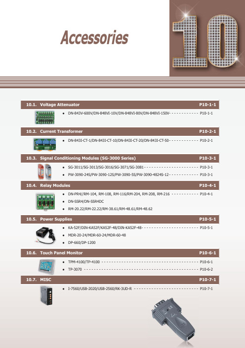
P10-1-1●DN-843V-600V/DN-848VI-10V/DN-848VI-80V/DN-848VI-150V- - - - - - - - - - - - P 10-1-1Current P10-2-1●DN-843I-CT-1/DN-843I-CT-10/DN-843I-CT-20/DN-843I-CT-50 - - - - - - - - - - - - P 10-2-1P10-3-1●SG-3011/SG-3013/SG-3016/SG-3071/SG-3081 - - - - - - - - - - - - - - - - - - - - - - P 10-3-1 ●PW-3090-24S/PW-3090-12S/PW-3090-5S/PW-3090-4824S-12 - - - - - - - - - - - - P 10-3-1Relay Modules P10-4-1●DN-PR4//RM-104, RM-108, RM-116/RM-204, RM-208, RM-216 - - - - - - - - - - - P 10-4-1 ●DN-SSR4/DN-SSR4DC●RM-20.22/RM-22.22/RM-38.61/RM-48.61/RM-48.62Power Supplies P10-5-1●KA-52F/DIN-KA52F/KA52F-48/DIN-KA52F-48 - - - - - - - - - - - - - - - - - - - - - - - P 10-5-1 ●MDR-20-24/MDR-60-24/MDR-60-48 ●DP-660/DP-1200P10-6-1●TPM-4100/TP-4100 - - - - - - - - - - - - - - - - - - - - - - - - - - - - - - - - - - - - - - - P 10-6-1 ●TP-3070 - - - - - - - - - - - - - - - - - - - - - - - - - - - - - - - - - - - - - - - - - - - - - - P 10-6-2MISC P10-7-1●I-7560/USB-2020/USB-2560/RK-3UD-R - - - - - - - - - - - - - - - - - - - - - - - - - - P 10-7-1AccessoriesProfessional Provider of High Quality I ndustrial C omputer P roducts and D ata A cquisition S ystems Vol. PAC 2.0.0A c c e s s o r i e s101Vout1GND Vout2GND Vout3GND+Vs GND F .G.NC Vin 1 -Vin 1+NC Vin 2 -Vin 2+NC Vin 3 -Vin 3+Vin 1 -Vin 1+Vin 2 -Vin 2+Vin 3 -Vin 3+Vin 4 -Vin 4+Vin 5 -Vin 5+Vin 6 -Vin 6+Vin 7 -Vin 7+Vin 8 -Vin 8++Vs GND F .G.Vout1 +OP Amp1OP Amp2OP Amp3OP Amp4OP Amp5OP Amp6OP Amp7OP Amp8Vout1 -Vout2 +Vout2 -Vout3 +Vout3 -Vout4 +Vout4 -Vout5 +Vout5 -Vout6 +Vout6 -Vout7 +Vout7 -Vout8 +Vout8 -DN-843V-600VDN-848VI-10V/DN-848VI-80V/DN-848VI-150V10.1. Voltage AttenuatorThe DN-800V series are voltage input attenuator . The maximum input range is from ±80 V to +/- 600 V and can be attenuated to ±10 V . The "I" version provide 3000 V DC intra-modules isolation and 3000 V DC channel to channel isolation to avoid the noise interference from inputs to outputs or channel to channel. It can be used with the analog input modules such as I-7017 and I-87017 etc. to measure the high voltage.DN-848VI-80VDN-848VI-150VAC/DC Source InputHigh Voltage Input Measurement Linear Attenuation Ratio High Input ImpedanceChannel to Channel Isolation forDN-848VI-10V , DN-848VI-80V and DN-848VI-150V 4 kV ESD Protection 3 kV Surge Protection RoHS ComplianceOperating Temperature: -25 ~ +75°C Easily Wire ConnectionDN-848VI-10VDN-843V-600V IntroductionApplicationsAppearanceProgrammable Automation Controller Products10-1-2Website:E-mail:*******************.PAC2.0.00Accessories101General Channels 8883Input Type AC/DC VoltageInput Range +/- 10 V pp+/- 80 V pp+/- 150 V pp+/- 600 V ppOutput Range +/- 10 V pp Accuracy1% of FSRChanel to Channel Isolation Yes, 3000 V DC-Bandwidth 30 KHz100 KHzInput Impedance> 1 M ΩIntra-module Isolation, Input to Output 3000 V DC -EMS Protection ESD (IEC 61000-4-2)+/- 4 kV contact for power line, input and output channels , +/- 8 kV air for random pointSurge (IEC 61000-4-5)+/- 3 kV for power linerPower Input Input Range +10 ~ +30 V DCPower Consumption 9.2 W9.2 W9.2 W0.56 WMechanicalDimensions (W x L x H)122 mm x 174 mm x 33 mm122 mm x 174 mm x 24.5 mmInstallation DIN-Rail MountingEnvironment Operating Temperature -25 ~ + 75°C Storage Temperature -30 ~ +75°CHumidity10 ~ 90% RH (non-condensing)8-channel 10 V Voltage Attenuator (RoHS)8-channel 80 V Voltage Attenuator (RoHS)8-channel 150 V Voltage Attenuator (RoHS)3-channel 600 V Voltage Attenuator (RoHS)MDR-20-24 CR24 V/1 A, 24 W Power Supply with DIN-Rail Mounting (RoHS)I-7017-G CR 8-channel Analog Input Module (RoHS)I-87017-G CR 8-channel Analog Input Module (RoHS)Selection GuideDN-84-x xx xxx Number of Channels 3: 3 channels 8: 8 channelsV: VoltageI: Channel to channel IsolationInput Voltage RangeDimensions (Units: mm)Bottom View Top View Bottom ViewTop View Left View Front View Rear ViewRight View Left View Front View Rear ViewRight View Speci fi cationsOrdering InformationAccessoriesProfessional Provider of High Quality I ndustrial C omputer P roducts and D ata A cquisition S ystems Vol. PAC 2.0.00102A c c e s s o r i e sDN-843I-CT-20DN-843I-CT-50DN-843I-CT-10DN-843I-CT-1 10.2. Current TransformerThe maximum input range is from ±1 A to +/- 50 A and can be attenuated to from ±1.6 V to ±10 V . The "I" version provide 3000 V DC intra-modules isolation and 3000 V DC channel to channel isolation to avoid the noise interference from inputs to outputs or channel to channel. It can be used with the analog input modules such as I-7017 and I-87017 etc. to measure the high current.AC/DC Source Input Linear Attenuation RatioHigh Current Input MeasurementIsolation InputChannel to Channel Isolation4 kV ESD Protection RoHS ComplianceOperating Temperature: -25 ~ +75°C Easily Wire ConnectionInstallationCh1 Current InputCh2 Current InputCh3 Current Input24 V DCCh1 OutputCh2 OutputCh3 OutputF.G. IntroductionApplicationsProgrammable Automation Controller Products10-2-2Website:E-mail:*******************.PAC2.0.00Accessories102General Channels 3Input Type AC/DC CurrentInput Range +/- 1 A+/- 10 A+/- 20 A+/- 50 AOutput Type AC/DC VoltageOutput Range +/- 1.6 V pp+/- 10 V pp+/- 10 V pp+/- 4 V ppCT Type Solid Core (closed)Accuracy1% of FSR Chanel to Channel IsolationYes, 3000 V rmsIntra-module Isolation, Input to Output 3000 V DC Bandwidth 50 KHz Input Impedance > 1 M ΩEMS Protection ESD (IEC 61000-4-2)+/- 4 kV contact for power line, input and output channels, +/- 8 kV air for random pointPower Input Input Range +10 ~ +24 V DCPower Consumption 1.2 WMechanicalDimensions (W x L x H)148 mm x 83 mm x 39 mmInstallation DIN-Rail Mounting Environment Operating Temperature -25 ~ + 75°C Storage Temperature -30 ~ +75°CHumidity10 ~ 90% RH (non-condensing)3-channel 1 A Current Transformer (RoHS)3-channel 10 A Current Transformer (RoHS)3-channel 20 A Current Transformer (RoHS)3-channel 50 A Current Transformer (RoHS)MDR-20-24 CR24 V/1 A, 24 W Power Supply with DIN-Rail Mounting (RoHS)I-7017-G CR 8-channel Analog Input Module (RoHS)I-87017-G CR8-channel Analog Input Module (RoHS)DN-84--xxxx xC: CurrentCT: Current TransformerInput Current RangeBottom ViewTop ViewLeft ViewFront ViewRight ViewNumber of Channels3: 3 channelsSelection GuideDimensions (Units: mm)Speci fi cationsOrdering InformationAccessoriesI C P roducts and D ata A cquisition S ystems Vol. PAC 2.0.00103A c c e s s o r i e s10.3. Signal Conditioning Modules (SG-3000 Series)DescriptionSG-3016SG-3071SG-3081PicturesAnalog Input Channel 11111Wiring Differential 2/3/4 wiresDifferential Differential Differential Signal ThermocoupleRTDStrain GaugeVoltage Current Type Type J, K, T , E, R, S, B, N, C, L,M, L2Pt100 α=0.00385, Pt100α=0.003916, Ni 120, Pt1000α=0.00385±10 mV , ±20 mV , ±30 mV ,±50 mV , ±100 mV ±5 V ,±10 V 0 ~ 20 mA, 4 ~ 20 mAResolution 12-bit 12-bit ---Accuracy ±0.2% of FSR±0.1% of FSR±0.1% of FSR±0.1% of FSR±0.1% of FSRInput Impedance 1.8 M Ω-- 1.6 M Ω250 ΩExcitation Voltage --0 ~ 10 V--Analog Output Channel 11111Current Output 0 ~ 20 mA 0 ~ 20 mA, 4 ~ 2 0mA 0 ~ 20 mA0 ~ 20 mA, 4 ~ 20 mA0 ~ 20 mA, 4 ~ 20 mA Voltage output 0 ~ 10 V0 ~ 5 V , 0 ~ 10 V±5 V , ±10 V , 0 ~ 5 V , 0 ~ 10 V±5 V , ±10 V0 ~ 5 V , 0 ~ 10 VSystem 3-way Isolation 1000 V DC Power Input 10 ~ 30 V DCPower Consumption 1.44 W1.2 W1.44 W 1.8 W1.61 WOperating Temperature -25 ~ +75°CDimensions (W x H x D)25 mm x 114 mm x 71 mmPW-3090-5SPW-3090-4824S-12PicturesInput 18 ~ 36 V (non-regulated)18 ~ 36 V (non-regulated)18 ~ 36 V (non-regulated)48 V (non-regulated)Output ********(Max.)********(Max.)5 V @ 2 A (Max.)********(Max.)Isolation 1000 V DCEf fi ciency83% Typical Operating Temperature -25 ~ +75°CDimensions (W x H x D)25 mm x 114 mm x 71 mmSG-3000 series signal conditioning modules are used to accept wide range of input signals, such as voltage, current, temperature (thermocouple and RTD) and provide 0 ~ 10 V DC , 0 ~ 20 mA, 4 ~ 20 mA output signals. It gives following good features for industrial applications • 3-way (power/input/output) isolation (1000 V DC )• Wide operating temperature (-25 ~ +75°C)• DIN-Rail mounting• Input and output connectors on the opposite side • Signal range con fi gureable by swtichIntroductionApplicationsProgrammable Automation Controller Products10-4-1Website:E-mail:*******************.PAC2.0.00Accessories104RM-38.61RM-48.61RM-48.62PicturesRelay Finder 20.22.9.024.4000Finder 22.22.9.024.4000Finder 34.51.7.024.0010FINDER - 40.61.7.024.0000FINDER - 44.62.7.024.0000Type Step RelayPower RelayChannel 1ContactForm A (DPST)Form A (DPST)Form C (SPDT)Form C (SPDT)Form C (SPDT)Operating Voltage Range 230 V AC 230 V AC 250 V AC 250 V AC 250 V AC Max. Load Current 16 A 20 A 6 A 16 A 10 A Operate Time 15 ms 15 ms 5 ms 7 ms 7 ms Release Time 8 ms8 ms3 ms 3 ms3 msLED Indicator -MechanicalDimensions (W x L x D)17.5 mm x 84 mm x 62.7 mm 76.5 mm x 6.5 mm x 89 mm75 mm x 15.5 mm x 78.5 mmInstallationDIN-Rail MountingNote1: RM-38.61: 5 pcs in one packageRM-48.61: 4 pcs in one package RM-48.62: 4 pcs in one packageNote2: RM-38-093.20is a 20-way jumper link for RM-38.61DN-SSR4PicturesRelay A5P-204UD3P-054Type Solid-State Relay Channel 4 channels ContactForm A (SPST)Operating Voltage Range 250 V AC /30 V DC50 V DCMax. Load Current 4 AOperate Time 1/2 Cycle + 1ms and below 0.5 ms and below (Resistance load)Release Time 1/2 Cycle + 1ms and below0.5 ms and below (Resistance load)LED Indicator Yes (for Relay status)MechanicalDimensions (W x L x D)101 mm x 77 mm x 66 mmInstallationDIN-Rail MountingPicturesRelay VE-24H5-K FINDER - 40.61.7.024.0000FINDER - 44.52.7.024.0000Type Power Relay Channel 4RM-104: 4 channels RM-108: 8 channels RM-116: 16 channels RM-204: 4 channels RM-208: 8 channels RM-216: 16 channels ContactForm C Form C (SPDT)Form C (DPDT)Operating Voltage Range 250 V AC /30 V DC250 V AC 250 V AC Max. Load Current 5 A 16 A 6 A Operate Time 10 ms (Typical)7 ms (Typical)8 ms (Typical)Release Time 5 ms (Typical)3 ms (Typical) 5 ms (Typical)LED Indicator Yes (for Relay status)MechanicalDimensions (W x L x D)96 mm x 103 mm x 34 mmRM-104: 79 mm x 87 mm x 63 mm RM-108: 135 mm x 87 mm x 63 mm RM-116: 270 mm x 87 mm x 63 mmRM-204: 90 mm x 87 mm x 63 mm RM-208: 169 mm x 87 mm x 63 mm RM-216: 327 mm x 87 mm x 63 mmInstallationDIN-Rail Mounting10.4. Relay ModulesI ndustrial C omputer P roducts and D ata A cquisition S 105A c c e s s o r i e s10.5. Power SuppliesModelsKA-52F DIN-KA52F KA-52F-48DIN-KA52F-48Input Range 100 ~ 250 V AC Frequency 50 ~ 60 HzOutput Power 24 V DC /1.04 A Max., 25 W48 V DC /0.52 A Max., 25 WMechanicalDimensions(W x H x D, Units: mm)54 x 93 x 36 68 x 107 x 50 54 x 93 x 36 68 x 107 x 50 Installation No-mountingDIN-Rail MountingNo-mountingDIN-Rail MountingEnvironmentalOperating Temperature 0 ~ +50°C Storage Temperature-20 ~ +85°CModelsMDR-20-24MDR-60-24MDR-60-48Input Range 100 ~ 250 V AC Frequency 50 ~ 60 HzOutput Power 24 V DC /1 A Max., 24 W24 V DC /2.5 A Max., 60 W48 V DC /1.25 A Max., 60 WMechanicalDimensions (W x H x D)22.5 mm x 90 mm x 100 mm 40 mm x 90 mm x 100 mm 40 mm x 90 mm x 100 mmInstallation DIN-Rail MountingEnvironmental Operating Temperature -20 ~ +70°C Storage Temperature-20 ~ +85°CModelsDP-660DP-1200Input Range 100 ~ 250 V AC Frequency 50 ~ 60 HzOutputPower 24 V DC /2.5 A Max., 60 W and5 V DC /0.5 A Max., 2.5 W24 V DC /5.0 A Max., 120 WMechanicalDimensions (W x H x D)44 mm x 145 mm x 158 mm 65 mm x 111 mm x 125 mmInstallation DIN-Rail MountingEnvironmentalOperating Temperature 0 ~ +50°C -10 ~ +70°C Storage Temperature-20 ~ +85°C-25 ~ +85°CKA-52F CR 24 V DC /1.04 A, 25 W Power Supply (RoHS)DIN-KA52F CR 24 V DC /1.04 A, 25 W Power Supply with DIN-Rail Mounting (RoHS)KA-52F-48 CR 48 V DC /0.52 A, 25 W Power Supply (RoHS)DIN-KA52F-48 CR48 V DC /0.52 A, 25 W Power Supply with DIN-Rail Mounting (RoHS)MDR-20-24 CR 24 V DC /1 A, 24 W Power Supply with DIN-Rail Mounting (RoHS)MDR-60-24 CR 24 V DC /2.5 A, 60 W Power Supply with DIN-Rail Mounting (RoHS)MDR-60-48 CR48 V DC /1.25 A, 60 W Power Supply with DIN-Rail Mounting (RoHS)DP-660 CR 24 V DC /2.5 A, 60 W and 5 V DC /0.5 A, 2.5 W Power Supply with DIN-Rail Mounting (RoHS)DP-1200 CR24 V DC /5.0 A, 120 W Power Supply with DIN-Rail Mounting (RoHS)KA-52F/DIN-KA52F KA52F-48/DIN-KA52F-48MDR-20-24MDR-60-24MDR-60-48DP-660DP-1200KA-52F KA-52F-48MDR-60-24/MDR-60-48DP-1200MDR-20-24DP-660DIN-KA52F DIN-KA52F-48Speci fi cationsSpeci fi cationsSpeci fi cationsOrdering InformationOrdering InformationOrdering InformationProgrammable Automation Controller Products10-6-1Website:E-mail:*******************.PAC2.0.00Accessories106TPM-4100TP-410010.6. Touch Panel MonitorTPM-4100/TP-410010.4" Touch Panel Monitor10.4" LCD supports 800 x 600 resolution Resistive Touch Panel Full-function OSD controlDriver Support: Windows 2k/XP/Vista/7/WESWinCE 5.0/6.0 LED backlight technology Aluminum Casing for TPM-4100 IP65 Comlipant Front PanelWide operating temperature: -25 ~ +75°CTPM-4100TP-4100Display Size 10.4”Resolution 800 x 600Max. Color 16.7 M Brightness (cd/m2)320Contrast Ratio 500 : 1Viewing Angle (H/V)140/130Backlight Life (hrs)50,000Touch Panel 4-wire5-wireanalog resistive, RS-232 or USB1.1 (Type B) interfaceInput SignalVGA (Analog RGB)MMI (Man Machine Interface)OSD Control Functions: Brightness, Contrast, Phase, Horizontal Position,Vertical Position and SharpnessPower Switch YesLED Indicators Power , Display signal is detectedPower Input Range +12 ~ 48 V DCPower Consumption 8.5 WMechanical MaterialAluminumPlasticDimensions (W x L x H)293 mm x 231 mm x 53 mm290 mm x 228 mm x 53 mm Installation Panel MonutingPanel Monuting, VESA (75 × 75) MountingIngress Protection Front panel: IP65Environmental Operating Temperature -25 ~ +75°C Storage Temperature -30 ~ +80°CAmbient Relative Humidity10 ~ 90% RH (non-condensing)10.4" (800 x 600) resistive touch panel monitor with RS-232 or USB interfaceAccessories: Power supply, VGA cable, RS-232 cable, USB cable, Mounting clamps and screws TP-4100 with Aluminum Casing273210.8TPM-4100 Dimensions (Units: mm)Speci fi cationsAppearanceOrdering InformationUSB USBOSD OSDRS-232RS-232VGAVGA Power Switch Power Switch VESA (75 × 75) Mounting12 ~ 48 DC IN12 ~ 48 DC INI ndustrial C omputer P roducts and D ata A cquisition S ystems Vol. PAC 2.0.00106A c c e s s o r i e sTP-30707" Touch Panel Monitor7" LCD supports 800 x 480 resolution Resistive Touch Panel Full-function OSD controlDriver Support: Windows 2k/XP/Vista/7/WESWinCE 5.0/6/0 LED backlight technology IP65 Comlipant Front PanelWide operating temperature: -20 ~ +70°CTP-3070Display Size 7”Resolution 800 x 480Brightness (cd/m2)320Contrast Ratio 500 : 1Viewing Angle (H/V)140/120Backlight Life (hrs)20,000Touch Panel 4-wire, analog resistive, RS-232 or USB1.1 (TypeB) interfaceInput SignalVGA (Analog RGB)MMI (Man Machine Interface)OSD Control Functions: Brightness, Contrast, Clock, Phase, Horizontal Position, Vertical Position and SharpnessPower Switch YesLED Indicators Power , Display signal is detectedPower Input Range +12 ~ 48 V DCPower Consumption 5 WMechanicalDimensions (W x L x H)213 mm x 148 mm x 44 mmCasingPlastic Ingress Protection Front panel: IP65Environmental Operating Temperature -20 ~ +70°C Storage Temperature -30 ~ +80°CAmbient Relative Humidity10 ~ 90% RH (non-condensing)7" (800 x 480) resistive touch panel monitor with RS-232 or USB interfaceAccessories: Power supply, VGA cable, RS-232 cable, USB cable, Mounting clamps and screwsDimensions (Units: mm)Speci fi cationsOrdering InformationProgrammable Automation Controller Products10-7-1Website:E-mail:*******************.PAC2.0.00Accessories 107InterfaceUSBCompatibility: USB 1.1 and 2.0 standards RS-232TxD, RxD, RTS, CTS, DSR, DTR, DCD, RI and GND; non-isolated Baud Rate300 ~ 115200 bps DriverWindows 98/ME/2000/XP/Vista (32/64-bit)/7 (32/64-bit)/LinuxMechanicalDimensions (W x H x D)33 mm x 60 mm x 15 mm Environmental Operating Temperature-25 ~ +75°C Storage Temperature -30 ~ +75°CInterfacePortsUpstream x 1 (Type B); Downstream x 4 (Type A)CompatibilitySpeci fi cation Rev. 2.0/1.1/1.0Transfer Speed480 Mbit/s-high speed mode Input Voltage Range+10 ~ +30 V DCMechanicalDimensions (W x H x D)33 mm x 107 mm x 78 mm InstallationDIN-Rail Mounting Environmental Operating Temperature -0 ~ +70°C Storage Temperature -20 ~ +80°CMechanical Dimensions (W x H x D)481 mm x 132 mm x 125 mm USB-2020 CR USB Audio Device (RoHS)RK-3UD-R 19" Rack Mounting Kit, 3U I-7560 CR USB to RS-232 Converter (RoHS)USB-2560 CR4-port Industrial USB 2.0 Hub (RoHS)USB-2560/S CR 4-port Industrial USB 2.0 Hub (RoHS) with GPSU06U-6 (Power Supply)RK-3UD-R I-7560InterfaceOutput ChannelsMono, Stereo (L + R)Input ChannelsMono, Stereo (L + R)ButtonHID volume up, volume down and Mute Input Voltage Range+10 ~ +30 V DCMechanicalDimensions (W x H x D)33 mm x 107 mm x 78 mm Installation DIN-Rail Mounting Environmental Operating Temperature-25 ~ +75°C Storage Temperature -40 ~ +85°C 10.7. MISC Speci fi cationsSpeci fi cationsSpeci fi cationsSpeci fi cationsOrdering InformationOrdering InformationOrdering Information Ordering Information USB to RS-232 Converter USB-2020USB-2560USB Audio Device 4-Port Industrial USB 2.0 Hub19" Rack Mounting Kit, 3UiP-84112-4-3 iP-88112-4-3 iP-84412-4-3 iP-88412-4-3 iP-8441-FD2-4-3 iP-8841-FD2-4-3 iP-84172-4-5Model Name PageiP-84472-4-5iP-88172-4-5iP-88472-4-5I-87005W5-2-1I-87013W5-2-1I-87015PW5-2-2I-87015W5-2-2I-8014W5-2-3I-8017DW5-2-3I-8017HCW5-2-3I-8017HW5-2-3I-8024DW5-2-3I-8024W5-2-3I-87017DW5-2-4I-87017RCDW5-2-4I-87017RCDW-AI5-2-4I-87017RCW 5-2-4I-87017RW 5-2-4I-87017W5-2-4I-87017W-A55-2-4I-87017ZW5-2-4I-87018PW5-2-5I-87018RW5-2-5I-87018W5-2-5I-87018ZW5-2-5I-87019PW5-2-6I-87019RW5-2-6I-87019ZW5-2-6I-87024W 5-2-7I-87024CW5-2-7I-87024DW 5-2-7I-87024RW 5-2-7I-87024UW 5-2-7I-87028CW5-2-7I-8040PW5-3-1I-8040W5-3-1I-8046W5-3-1I-8048W5-3-1I-8051W5-3-1I-8052W5-3-1I-8053W5-3-1I-8053PW5-3-1Model Name PageI-8058W5-3-1I-87040W5-3-2I-87040PW5-3-2I-87046W5-3-2I-87051W5-3-2I-87052W5-3-2I-87058W5-3-2I-87059W5-3-2I-87053W5-3-3I-87053PW5-3-3I-87053W-A55-3-3I-87053W-AC15-3-3I-87053W-E55-3-3I-8037W5-3-4I-8041W5-3-4I-8041RW5-3-4I-8041AW5-3-4I-8056W5-3-4I-8057W5-3-4I-8057RW5-3-4I-8057PW5-3-4I-8060W5-3-4I-8064W5-3-4I-8068W5-3-4I-8069RW5-3-4I-8069W5-3-4I-87037W5-3-5I-87041W 5-3-5I-87057W5-3-5I-87057PW5-3-5I-87061W5-3-5I-87064W5-3-5I-87065W5-3-5I-87066W5-3-5I-87068W5-3-5I-87069W5-3-5I-87069PW5-3-5I-8042W5-3-6I-8050W5-3-6I-8054W5-3-6I-8054RW5-3-6I-8055W5-3-6Model Name PageI-8063W5-3-6I-87042W5-3-7I-87054W5-3-7I-87055W5-3-7I-87063W5-3-7I-8026PW5-4-1I-87016W5-4-1I-87026PW5-4-1I-87089W/S5-5-1I-8084W5-6-1I-8088W5-6-1I-87082W5-6-1I-87084W5-6-1I-87088W5-6-1I-8092F5-7-1I-8093W5-7-1I-80945-7-1I-8094A5-7-1I-8094F5-7-1I-8094H5-7-1I-75105-8-1I-7510A5-8-1I-7510AR5-8-1I-75135-8-1I-7514U5-8-1I-7520 5-8-1I-7520A5-8-1I-7520AR5-8-1I-7520R5-8-1I-7520U45-8-1I-75515-8-1I-8112iW5-8-1I-8114iW5-8-1I-8114W5-8-1I-8142iW5-8-1I-8144iW5-8-1I-25325-9-2I-25335-9-2I-75305-9-2I-7530A5-9-2I-7530A-MR5-9-2I-7530-FT5-9-2Model IndexI-75315-9-2 I-75325-9-2 I-7540D5-9-2 I-7540D-MTCP5-9-2 I-7540D-WF5-9-2 I-75655-9-2I-7565-H15-9-2 I-7565-H25-9-2 I-8120W5-9-2 I-8123W5-9-2 I-8124W5-9-2 I-871235-9-2 I-871245-9-2 I-87H17W5-10-1 I-87H24W5-10-1 I-75475-10-1 I-75675-10-1 I-75705-10-1 I-8172W5-11-1 I-8212W5-12-1 I-8212W-3GWA5-12-1 I-8213W5-12-1 I-8213W-3GWA5-12-1 I-87211W 5-12-1 iP-8441-MTCP6-3-2 iP-8841-MTCP6-3-2 I-7188XG7-1-6 I-7188XGD7-1-6 I-71887-1-9 I-7188D7-1-9 I-7188XA7-1-9 I-7188XAD7-1-9 I-7188XB7-1-9 I-7188XBD7-1-9 I-7188XC7-1-9 I-7188XCD7-1-9 I-7188EA7-1-11 I-7188EAD7-1-11 I-7188EX7-1-11 I-7188EXD7-1-11 I-756010-7-1 iDCS-88309-1-3USB-87P25-4-2USB-87P45-4-2USB-87P85-4-2USB-202010-7-1USB-256010-7-1WP-8131 2-2-3WP-84312-2-3WP-88312-2-3WP-81412-2-3WP-84412-2-3WP-88412-2-3WP-80512-2-3WP-83512-2-3WP-87512-2-3WP-81372-2-6WP-84372-2-6WP-88372-2-6WP-81472-2-6WP-84472-2-6WP-88472-2-6WP-80572-2-6WP-83572-2-6WP-87572-2-6WP-81392-2-11WP-84392-2-11WP-88392-2-11PROFI-82556-6-2PROFI-84556-6-2PROFI-88556-6-2PW-3090-5S10-3-1PW-3090-12S10-3-1PW-3090-24S10-3-1PW-3090-4824S-1210-3-1USB-87P15-4-2iDCS-8830R9-1-3PROFI-81556-6-2XP-8349-Atom-CE62-1-14 XP-8749-CE62-1-14 XP-8749-Atom-CE62-1-14 X1017-2-3 X1067-2-3 X1077-2-3 X1107-2-3 X1117-2-3 X2007-2-3 X2027-2-3 X2037-2-3 X3027-2-3 X3037-2-3 X3047-2-3 X3057-2-3 X3087-2-3 X3107-2-3 X3247-2-3 X5037-2-3 X5047-2-3 X5057-2-3 X5067-2-3 X5077-2-3 X5087-2-3 X5097-2-3 X5107-2-3 X510-1287-2-3 X5117-2-3 X5187-2-3 X6037-2-3 X6077-2-3 X6087-2-3 X7027-2-3 X7037-2-3 XV1168-4-1 XV107Ai8-4-2 XV107i8-4-2 XV110i8-4-2 XV111Ai8-4-2 XV111i8-4-2 XW1078-4-2 XW107i8-4-2μPAC-51078-1-7μPAC-5107D8-1-7μPAC-52078-1-7μPAC-5207D8-1-7μPAC-53078-1-7μPAC-5307D8-1-7μPAC-55078-1-7μPAC-5507D8-1-7 XW110i8-4-2XV304i8-4-3XV305i8-4-3XV308i8-4-3XV310i8-4-3XW3048-4-4XW3108-4-4XW310C8-4-4XW5068-4-5XW5078-4-5XW5088-4-5XW5098-4-5XW511i8-4-5XW5148-4-5μμPAC-7186EX 7-1-4μPAC-7186EXD 7-1-4μPAC-7186EX-FD 7-1-4μPAC-7186EXD-FD 7-1-4μPAC-7186EX-SM 7-1-4μPAC-7186EXD-SM 7-1-4μPAC-7186EG7-1-6μPAC-7186EG-D7-1-6μPAC-50018-1-6μPAC-5001D8-1-6μPAC-5001-FD8-1-6μPAC-5001D-FD8-1-6μPAC-5101 8-1-6μPAC-5101D 8-1-6μPAC-52018-1-6μPAC-5201D8-1-6μPAC-53018-1-6μPAC-5301D8-1-6μPAC-55018-1-6μPAC-5501D8-1-6μPAC-5801 8-1-6μPAC-5801D8-1-6μPAC-59018-1-6μPAC-5901D8-1-6μPAC-50078-1-7μPAC-5007D8-1-7WP-81492-2-11WP-84492-2-11WP-88492-2-11WP-80592-2-11WP-83592-2-11WP-87592-2-11WP-51418-2-4WP-5141-OD8-2-4WP-52318-2-6WP-5231-2G8-2-6WP-5231-3G8-2-6WP-5231-GPS8-2-6WP-5231-WF8-2-6WP-5231-ZH8-2-6WP-5231-ZS8-2-6WP-51478-2-8WP-5147-OD8-2-8WP-51498-2-11WP-5149-OD8-2-11XXP-8041 2-1-5XP-8141-Atom2-1-5XP-83412-1-5XP-8341-Atom2-1-5XP-87412-1-5XP-8741-Atom2-1-5XP-8041-CE62-1-7XP-8141-Atom-CE62-1-7XP-8341-CE62-1-7XP-8341-Atom-CE62-1-7XP-8741-CE62-1-7XP-8741-Atom-CE62-1-7XP-8047-CE62-1-9XP-8147-Atom-CE62-1-9XP-8347-CE62-1-9XP-8347-Atom-CE62-1-9XP-8747-CE62-1-9XP-8747-Atom-CE62-1-9XP-8049-CE62-1-14XP-8149-Atom-CE62-1-14XP-8349-CE62-1-14 Model Index。
Yokogawa电子有限公司UT35A、UT32A数字显示控制器说明书
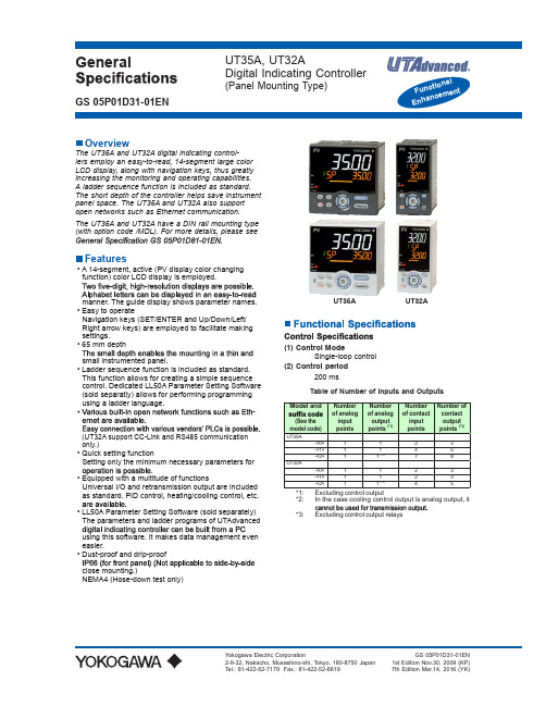
GeneralUT35A, UT32ADigital Indicating Controller(Panel Mounting Type)GS 05P01D31-01ENOverviewThe UT35A and UT32A digital indicating control-lers employ an easy-to-read, 14-segment large colorLCD display, along with navigation keys, thus greatly increasing the monitoring and operating capabilities. A ladder sequence function is included as standard. The short depth of the controller helps save instrument panel space. The UT35A and UT32A also support open networks such as Ethernet communication.The UT35A and UT32A have a DIN rail mounting type (with option code /MDL). For more details, please seeFeatures• A 14-segment, active (PV display color changing function) color LCD display is employed.manner. The guide display shows parameter names.• Easy to operateNavigation keys (SET/ENTER and Up/Down/Left/Right arrow keys) are employed to facilitate making settings.• 65 mm depthsmall instrumented panel.• Ladder sequence function is included as standard. This function allows for creating a simple sequence control. Dedicated LL50A Parameter Setting Software (sold separatly) allows for performing programming using a ladder language.-(UT32A support CC-Link and RS485 communicationonly.)• Quick setting functionSetting only the minimum necessary parameters for.• Equipped with a multitude of functionsUniversal I/O and retransmission output are included as standard. PID control, heating/cooling control, etc. • LL50A Parameter Setting Software (sold separately) The parameters and ladder programs of UTAdvanced using this software. It makes data management even easier.• Dust-proof and drip-proof close mounting.)NEMA4 (Hose-down test only)(1) Control Mode Single-loop control (2) Control period 200 msTable of Number of Inputs and Outputs*2: In the case cooling control output is analog output, it *3:Excluding control output relaysUT35A UT32AControl Computation Function(1) Types of control • PID control• ON/OFF control (*4)• Two-position two-level control (*5)• Heating and cooling control (*5)(2) Control Computation Function-eter groupsRespectively, four sets of target setpoints, alarm• Measured input zone PID • Target setpoint zone PID• Reached target setpoint zone PID(c) Auto-tuningheating/cooling control.)(d) “Super” function: Overshoot-suppressing function (e) “Super 2” function: Hunting-suppressing function (f) STOP preset output function(g) Input ERROR preset output function (h) MANUAL preset output functionAlarm FunctionsContact I/O FunctionThis function allows for allocating the input errorcondition, operation condition, alarm condition or otherconditions to the contact input and contact output.Ladder Sequence Functionpoints. (See the model code.)Physical InterfaceEthernet Standard : IEEE802.3 (10BASE-T, 100BASE-TX)Max segment length : 100mRS-485 Standard : EIA RS-485Communication method : Two-wire harf-duplex or four-wire harf-duplex, start-stop synchoronization,and non-proceduralMaximum communication distance : 1200mCorresponding version : DP V0Baud rate : 9.6k, 19.2k, 45.45k, 93.75k, 187.5k, 0.5M, 1.5M, 3M, 6M, 12M, AUTO (*3)Communication distance : 1200m (9.6k to 93.75k) 1000m (187.5k)400m (0.5M) 200m (1.5M)100m (3M to 12M)CC-Link Supported version : Remote device (Ver.1.10, Ver.2.00)When using optical repeater : 7.6 km (156k) to 4.3 km (10M)Control output (heating-side output): 1 point(standard), which is shared with transmissionoutputCooling-side output: 1 point, which isshared with transmission output• Output functionsCurrent output or voltage pulse output• Current output4 to 20 mA DC or 0 to 20 mA DC/load resistance• Current output accuracy±0.1% of span (however, ±5% of span for 1 mAor less)The accuracy is that in the standard operatingconditions: 23 ±2°C, 55 ±10%RH, and powerfrequency at 50/60 Hz• Voltage pulse outputApplication: time proportional outputON voltage: 12 V or more/load resistance of 600OFF voltage: 0.1 V DC or lessTime resolution: 10 ms or 0.1% of output value,whichever is largerwith 15 V DC loop power supplyAdditional 1 points when analog control output arenot used• Output function: current output4 to 20 mA DC or 0 to 20 mA DC/load• Current output accuracy (conversion accuracy from PV display on the set scale): ±0.1% of span (how-ever, ±5% of span for 1 mA or less)conditions: 23 ±2°C, 55 ±10%RH, and powerfrequency at 50/60 HzThis is not conversion accuracy through inputoutput itself.with retransmission output• Supply voltage: 14.5 to 18.0 V DCcircuit current limiting circuit)Within 1 s(Response time at 63% of transmission output when a 90% of input span)Control relay output: one 1c-contact pointControl output of heating and cooling control:2 1a-contact pointsAlarm output: 3 1a-contact points (Common isseparated)• Contact rating1c-contact: 3 A at 250 V AC or 3 A at 30 V DC (resistance load)1a-contact:For alarm output: 1 A at 240 V AC or 1 A at30 V DC (resistance load)For output of heating and cooling controlrelay output: 3 A at240 V AC or 3 A at 30 V DC (resistance load)of 10 mA or more.of 1 mA or more.• Application: time proportional output, alarm output, FAIL output, etc.• Time resolution for control output: 10 ms or 0.1% of output value, whichever is larger• Output form: open collector (sink current)• Output contact capacity: Up to 24 V DC, 50 mA• Output time resolution: min 200 ms• Application: alarm output, FAIL output, etc.• Position signal inputof total resistance100% side and slide line: with disconnectiondetection0% side: without disconnection detection Current input: 4 to 20 mA DC (with disconnectiondetection)• Sampling period: 50 ms• Measurement resolution: 0.1% of input span• Position proportional relay outputUT35A: Two 1a-contact points , 3 A at 250 VAC or 3A at 30 V DC (resistance load) UT32A: Two 1a-contact points , 3 A at 240 VAC or 3A at 30 V DC (resistance load) *:• Function: Measures the heater current using an external current transformer (CT) and generates a than the disconnection detection value.output)• CT input range: 0.0 to 0.1 Arms (0.12 Arms or more• Heater current alarm setting range: OFF, 0.1 to 300.0 ArmsHeater current measured value display range: 0.0 to 360.0 Arms• Recommended CT: CT from URD Co. Ltd.range: 0.1 to 80.0 Armsrange: 0.1 to 180.0 Arms• Heater current measurement period: 200 ms• Heater current measurement accuracy: ±5% of CT input range span ±1 digit (CT error is not included)• Heater current detection resolution: Within 1/250 of CT input range span• Disconnection detection ON time: Minimum 200 ms. (for time proportional output)(for /LP Option)• Application: Power is supplied to the 2-wire transmitter.• Supply voltage: 21.6 to 28.0 V DC• Rated current: 4 to 20 mA DCcircuit current limiting circuit)Safety and EMC Standards• Safety:Compliant with IEC/EN 61010-1 (CE), IEC/EN 61010-61010-1.Installation category: IIPollution degree: 2Measurement category: I (CAT I) (UL, CSA)O (Other) (CE)Rated measurement input voltage: Max. 10 V DCRated transient overvoltage: 1500 V (*)*: This is a reference safety standard value for measure-ment category I of CSA/UL 61010-1, and for measure-ment category O of IEC/EN 61010-2-030. This value isnot necessarily a guarantee of instrument performance.• EMC standards:Compliant withCE markinglocations),EN 61326-2-3*: The instrument continues to operate at a measurement accuracy of within ±20% of the range during testing.EN 55011 Class A, Group 1EN 61000-3-2 Class AEN 61000-3-3EMC Regulatory Arrangement in Australia and New ZealandEN 55011 Class A, Group 1• KC marking: Electromagnetic wave interference prevention standard, electromagnetic wave protection standard compliance• Power supplyRated voltage: 100 to 240 V AC (+10%/-15%), 50/60 Hz24 V AC/DC (+10%/-15%) (When the • Power consumption: UT35A: 18 VA (For the /DCoption. DC: 9 VA, AC: 14 VA)UT32A: 15 VA (For the /DCoption. DC: 7 VA, AC: 11 VA)• Storage: Nonvolatile memory•• Withstanding voltagesecondary terminals (UL, CSA)secondary terminals (CE)terminals(Primary terminals = Power (*) and relay outputterminals, Secondary terminals = Analog I/O signal terminals, contact input terminals, communication terminals, and functional grounding terminals.)*: Power terminals for 24 V AC/DC models are thesecondary terminals.• Insulation resistanceBetween power supply terminals and a grounding The circuits divided by lines are insulated mutually.Control and transmission (analog) output terminal(not isolated between the analog output terminals)Valve position (feedback) input terminalPV (universal) input terminalControl relay (c-contact or 2 a-contact) output terminalAlarm-1 relay (a-contact) output terminalAlarm-2 relay (a-contact) output terminalAlarm-3 relay (a-contact) output terminalPosition proportional relay output terminalInternalcircuitsPowersupplyContact input terminal (All)RS485 communication terminal (2 ports)24 V DC loop power supply terminalEthernet/PROFIBUS-DP/CC-Link/DeviceNetcommunication terminalCurrent transformer input terminalContact output (transistor) terminalEnvironmental ConditionsNormal operating conditionsmounting: -10 to 40 °C)UT35A; 0 to 40 °C for UT32A.UT32A with CC-Link option)1.5 mm or less(at 9 to 150 Hz) 4.9 m/s2 or less, 1 oct/min for 90 min-utes each in the three axis directions2, 15 s or less• Impact: 98 m/s2 or less, 11 msec.• Warm-up time: 30 minutes or more after the power is turned on• Start-up time within 10 sTransportation and Storage Conditions• Temperature: -25 to 70°C• Temperature change rate: 20°C per hour or less• Humidity: 5 to 95%RH (no condensation)Effects of Operating ConditionsFor voltage or TC input:range)/°C, whichever is greaterFor RTD input:For current input:±0.01% of F.S. (instrument range)/°CFor analog output:±0.02% of F.S./°C or lessFor analog input: ±0.05% of F.S. (instrument range) or lessFor analog output: ±0.05% of F.S. or less(Each within rated voltage range)Block DiagramSingle Loop Control(Current when retransmission output)PV inputContact inputsEquipped as standardEquipped as standard.UT35AUnit: mm[(N-1)×96+92]+0.80+.892“N” stands for the number of controllers to beinstalled.• General mounting• Side-by-side close mountingNormal tolerance:±(value of JIS B 0401-1998 tolerance class IT18)/2UT32AUnit: mm[(N-1)×48+45]+0.60+.892• General mounting• Side-by-side close mounting“N” stands for the number of controllers to beinstalled.However, the measured value applies if N5.Normal tolerance:±(value of JIS B 0401-1998 tolerance class IT18)/2Construction, Mounting, and Wiring• Dust-proof and drip-proof: IP66 (Front panel) (Not*: Hose-down test only•• Case color: White (Light gray) or Black (Light Char-coal gray)• Weight: 0.5 kg or less• External dimensions (mm):UT35A: 96 (width) x 96 (height) x 65 (depth from thepanel surface)UT32A: 48 (width) x 96 (height) x 65 (depth from thepanel surface)one each for upper and lower mounting• Panel cutout dimensions (mm):UT35A: 92+0.8/0 (width) x 92+0.8/0 (height)UT32A: 45+0.6/0 (width) x 92+0.8/0 (height)-zontal. No downward titling allowed.• Wiring: M3 screw terminal with square washer (signalwiring and power)Standard accessoriesUser’s ManualURL: /ns/ut/im/。
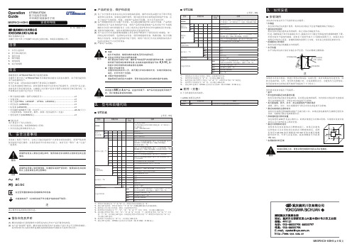
YOKOGAWA横河温度控制器UT5xA中文说明书(1)
⏹产品的安全、保护和改装(1)为了安全使用本仪表以及由本仪表构成的系统,操作时请务必遵守本手册中所述说明和注意事项,如果违反操作规程,则可能会使本仪表所提供的保护失效。
由以上情况产生的质量、性能、功能和产品的安全问题,本公司不承担责任。
(2)客户需根据需要自行实施下列安装:有关避雷器的保护和/或安全电路;产品所控制系统以及产品本身的保护设备;使用产品所控制系统或产品本身某个环节或线路的安全设计或失效保险设计;以及/或者其它保护性和安全性电路的设计和安装。
(3)更换零件或耗材时,请务必使用横河电机认可的备用零件。
(4)本产品并不针对直接影响或威胁人类生命的严酷条件下使用而设计或制造。
如一些特定的应用场所,包括核电站设备、使用放射能的设备、铁路设施、航空设施和医疗设备等。
如果在这样的环境下使用,则用户需自行负责在系统附加设备中包括以及保证个人安全的设备。
(5)严禁对产品改装。
● 电源在打开电源前,确保仪表的电源电压符合电源电压。
●切勿在可燃性气体中使用本仪表请不要在有可燃性气体、爆炸性气体或蒸气的场所操作本仪表,在这样的环境下使用本仪表非常危险,在有高浓度的腐蚀性气体(H 2S ,SO X 等)环境中长时间使用本仪表容易引起故障。
●不要打开仪表外壳非横河电机的技术人员,请不要打开本仪表的外壳。
仪表内局部存在高压,打开外壳十分危险。
●对保护性结构的损坏请按照本手册所述方法操作,否则可能会损坏本仪表的保护性结构。
本设备为EMC 的A 类产品。
在室内环境下,本产品可能会造成无线电干扰,用户需要采取适当的措施。
2.型号和后缀代码⏹UT55A [类型:S1]*1:类型2代码指定为“1”或“6”时,类型3代码只能指定为“0”。
*2:指定/LP 选项时,类型2代码中“1”和“2”的RS-485通信为2线制系统。
*3:指南显示可以显示为英语、德语、法语和西班牙语。
*4:将类型2代码指定为“1”、“2”、“4”、“5”或“7”任何一种时,可以指定/DR 选项。
Yokogawa(横河)DCS培训讲义
Offshore
Center Domain
Ethernet HIS
DSU DSU
Local Domain
DSU
Ethernet HIS
DSU
CGW V net
CGW V net
FCS
Two systems can be connected by Wide Area CGW.
紧凑型控制站 标准控制站(RIO) 标准控制站(FIO) Vnet/IP 控制站(FIO)
P15
YCH LCS DCS培训资料
域构成配置
最小配置 域内最大配置 系统最大规模
V net
● ● ●
● ● ●
V-net
● ● ●
SFCS
LFCS KFCS LFCS KFCS :1,000,000 per Sys :64 :20 km :20 km per FCS :10 M :2 km per FCS
P5
YCH LCS DCS培训资料
CS1000/CS3000版本发展与升级
Shipment of Ver.1
R1
Shipment of Ver. 2
Shipment of Ver. 3
R1.03 Version upgrade R2.01 R2.05 R2.06 R2.10 R2.20~23 Revision upgrade
P17
YCH LCS DCS培训资料
HUB
Ethernet
HIS PRT EWS
48
59 01.59
64 01.64
v
扩展型串 行背板总 线
V net v
FCU
ESB bus Local Node
Yokogawa DL系列差分探测器(Model 700924)用户手册说明书
User's ManualThank you for purchasing the Differential Probe (Model 700924) for the DL series. To ensure correct use, please read this manual thoroughly before beginning operation. After reading the manual, keep it in a convenient location for quick reference whenever a question arises during operation.IM 700924-01E IM 700924-01EModel 700924Differential Probe for the DL SeriesYOKOGAWA ELECTRIC CORPORATION, Communication & Measurement Business Headquarters Phone: (81)-422-52-67689-32, Nakacho 2-chome, Musashino-shi, Tokyo, 180-8750 JAPANYOKOGAWA CORPORATION OF AMERICA Phone: (1)-770-253-70002 Dart Road, Newnan, Ga. 30265-1094, U.S.A.YOKOGAWA EUROPE B.V. Phone: (31)-33-4641858Databankweg 20, 3821 AL, Amersfoort, THE NETHERLANDS YOKOGAWA ENGINEERING ASIA PTE. LTD. Phone: (65)-624199335 Bedok South Road, Singapore 469270, SINGAPORE7th Edition7th Edition : October 2007 (YK)All Rights Reserved, Copyright © 2007, Yokogawa Electric CorporationSafety PrecautionsMake sure to comply with the safety precautions mentioned hereafter when handling the probe.Yokogawa Electric Corporation assumes no responsibility for any consequences resulting from failure to comply with these safety precautions. Also, read the User’s Manual of the measuring instrument thoroughly so that you are fully aware of its specifications and handling, before starting to use the probe.The following symbols are used on this instrument.Warning: handle with care. Refer to the user’s manual or service manual. This symbol appears on dangerous locations on the instrument which require special instructions forproper handling or use. The same symbol appears in the corresponding place in the manual to identify those instructions. Risk of electric shockMake sure to comply with the following safety precautions in order to prevent accidents such as an electric shock which impose serious health risks to the user and damage to theGrounding of the measuring instrumentThe protective grounding terminal of the measuring instrument must be connected to ground.Earth cable of the probeMake sure to connect the earth cable of the probe to the ground (grounding potential). Do not operated with suspected failuresIf you suspect that there is damage to this probe, have it inspect by a service personnel.Observe maximum working voltageTo avoid any injury,do not use the probe above 1400 Vpeak between each input lead and earth or between the two inputs.This voltage rating applies to both 1/100 and 1/1000 settings.Must be groundedThis probe must be grounded with the BNC shell and an auxiliary grounding terminal, through the grounding conductor of the power cord of the measuring instrument or other appropriate grounding conductor. Before making connections to the input terminals of the product, ensure that the output connector is attached to the BNC connector of the measuring instrument and the auxiliary grounding terminal is connected to a proper ground, while the measuring instrument is properly grounded.Do not operate without coverTo avoid electric shock or fire hazard, do not operate this probe with the cover removed.Do not operate in wet/damp conditionsTo avoid electric shock, do not operate this probe in wet or damp conditions.Do not operate in explosive atmosphereTo aviod injury or fire hazard, do not operate this probe in an explosive atmosphere.Avoid exposed circuitryTo avoid injury, remove jewelry such as rings, watches, and other metallic objects. Do not touch exposed connections and components when power is present.CAUTIONMaximum input voltageDo not apply any voltages exceeding the maximum input voltage to the probe.Correct use of the power supplyPower the probe with either 4 AA dry cells, a 6 VDC/200 mA or 9 VDC/150 mA externalpower supply, or by connecting the probe’s power cable to a probe power supply terminal on a DL series measuring instrument or to the 700938 or 701934. Operating the probe under a power supply greater than the voltage specified above may cause damage to the instrument. Connecting the external power supply to the probeAlways turn OFF the probe’s power switch when connecting or disconnecting the external power supply. Also, do not install the dry cells when using an external power supply.Operating environment limitationsSee below for operating environment limitations.CAUTIONThis product is a Class A (for industrial environments) product. Operation of this product in a residential area may cause radio interference in which case the user is required to correct the interference.Waste Electrical and Electronic Equipment (WEEE), Directive 2002/96/EC (This directive is only valid in the EU.)This product complies with the WEEE Directive (2002/96/EC) marking requirement. This marking indicates that you must not discard this electrical/electronic product in domestic household waste.Product CategoryWith reference to the equipment types in the WEEE directive Annex 1, this product is classified as a “Monitoring and Control instrumentation” product.Do not dispose in domestic household waste. When disposing products in the EU, contact your local Yokogawa Europe B. V. office.The Following Symbols are Used in this Manual.Improper handling or use can lead to injury to the user or damage to the instrument. This symbol appears on the instrument to indicate that the user must refer to theuser’s manual for special instructions. The same symbol appears in the corresponding place in the user’s manual to identify those instructions. In the manual, the symbol is used in conjunction with the word “WARNING” or “CAUTION.”WARNING Calls attention to actions or conditions that could cause serious or fatal injury to theuser, and precautions that can be taken to prevent such occurrences.CAUTION Calls attentions to actions or conditions that could cause light injury to the user ordamage to the instrument or user’s data, and precautions that can be taken to prevent such occurrences.NoteCalls attention to information that is important for proper operation of the instrument.1 DescriptionBy using this device, oscilloscopes with single-ended input can be easily used as oscilloscopes with differential inputs.2 Appearance22 Pinchers tips3 Ground extention lead (length = 100 cm)Power cable*Pinchers tip B9852MJ Black: B9852MM, Red: B9852MN* Power can be supplied from the DL, 700938,or 701934.Optional Accessories (Sold Separately)3 Installing/Replacing the Dry CellsShift the lid at the back side of the probe and install/replace the four dry cells. The dry cells are not installed on receipt of the instrument.4 Operation1. Install four AA cells. When using an external power supply, do not install the dry cells. Supply power only through the external power supply.2. Simply plug-in the BNC output connector to the vertical input of a oscilloscope, and connect the auxiliary grounding terminal to a proper ground. If necessary, use a ground extention lead.3. Select the proper range setting. For higher resolution and less noise when measuring signals below 350V, switch the attenuation to 1/100. Otherwise, set the attenuation to 1/1000 when measuring signals above 350V.4. If the offset voltage is large, short the top of input leads, and turn the ADJUST variable resistor (DC voltage adjustment) using a flat-head screwdriver to adjust the offset voltage.• To protect against electric shock the ground side of the output cable (the shielded side of the BNC connector) must be grounded.• Make sure to avoid an electric shock when connecting the probe to the object ofmeasurement. Do not remove the probe from the measuring instrument after the object of measurement is connected.• When disconnecting the probe BNC output connector, first turn OFF the power to the circuit under measurement. Then, disconnect the probe from the high voltage parts of the circuit under measurement.• When replacing batteries or connecting an external power supply, first turn OFF the power to the circuit under measurement. Then, remove the input lead from the circuit under measurement.CAUTION• This probe is to carry out differential measurement between two points on the circuit under measurement. This probe is not for electrically insulating the circuit under measurement and the measuring instrument.• Use a soft cloth to clean the dirt. Prevent damage to the probe. Avoid immersing the probe, using abrasive cleaners, and using chemicals contains benzene or similar solvents.Note• Connect the BNC connector to the input terminal of the oscilloscope and for two pointmeasurement (differential measurement), connect both input leads. Because the performance declines in case you carry out measurements with only one input lead connected, make sure to always connect both.• Accurate measurement may not be possible near objects with strong electric fields (such as cordless equipment, transformers, or circuits with large currents).5 SpecificationsItemSpecificationsFrequency bandwidth *1DC to 100 MHz (−3 dB)Input typeBalancing difference inputAttenuation ratioswitched ratios of 100:1 and 1000:1Output offset voltage *1 *2±7.5 mVInput resistance and capacity 4 M Ω + 10 pF each side to groundDifferential allowable voltage ±1400 V (DC + ACpeak) or 1000 Vrms at 1000:1 attenuation (between + − terminal)±350 V (DC + ACpeak) or 250 Vrms at 100:1 attenuation Max common mode voltage ±1400 V (DC + ACpeak) or 1000 Vrms Max input voltage(to ground)±1400 V (DC + ACpeak) or 1000 VrmsCMRR (typical)*160 Hz: less than −80 dB; 1 MHz: less than −50 dB Output voltage *1±3.5 V (DC + ACpeak)Output impedance Using 1 M Ω input system oscilloscopeGain accuracy *1±2% (common mode voltage ≤ 400 V and ≥ −400 V)±3% (common mode voltage ≤ 1000 V and ≥ −1000 V)Operating environment 5 to 40°C, 25 to 85% (no condensation)Storage environment −30 to 60°C, 25 to 85% (no condensation)Operating altitude 2,000 m or lessPower requirements *3Internal battery: four dry cells (AA, R6)External power supply:6 VDC/200 mA or more, or 9 VDC/150 mA or more.From the DL series instrument’s probe power supply, 700938, or 701934 using the probe’s power supply cable. Cell life time In continuous duty, approx. 2 hoursDimensions 207 mm × 83 mm × 38 mm (excluding connector and cable)WeightApprox. 800 g ( excluding the dry cells)Withstanding voltage 2000 VACrms (between input terminal and BNC-ground), for 5 minutesSafety standardsComplying standards EN61010-031Measurement category III *4: 1400 V (DC + ACpeak)Pollution degree 2*5EmissionComplying standardsEN61326, EN55011, EN61000-3-2, EN61000-3-3This product is a Class A (for industrial environment) product. Operation of this product in a residential area may cause radio interference in which case the user is required to correct the interference.ImmunityComplying standards EN61326*1 When the power supply voltage from the dry cells is 5 V or more, or when using an external power supply.*2 Ambient temperature 23±5°C*3 When the capacity of dry cells goes down LED blinks. In such a case, replace the dry cells. Also, do not install the dry cells when using an external power supply.*4This equipment is for measurement category III (CAT III). Do not use it with measurement category IV (CAT IV). CAT III applies to measurement of the distribution level, that is , building wiring, fixed installations. CAT IV applies to measurement of the primary supply level, that is, overhead lines, cable systems, and so on.*5 Pollution degree applies to the degree of adhesion of a solid, liquid, or gas which deteriorates withstandvoltage or surface resistivity. Pollution degree 2 applies to normal indoor atmospheres (with only non-conductive pollution).Input voltage deratingFrequency (Hz)0.1 M1010010001400 1 M 10 M 100 M M a x i n p u t v o l t a g e (V )1981。
YOKOGAWA压力变送器介绍

Capacitance 电容 PiezoResistance 压电电阻式
Metal Resonant Wire金属丝谐振
Silicon Resonant 硅谐振式
Force Balance 力平衡式
单晶硅谐振式差压变送器
YOKOGAWA压力变送器传感器
硅谐振传感器
硅谐振式差压变送器工作原理
信号终端 低压腔
Close Tank
Transmitter Transmitter Dry leg is used for the Wet leg is used for the liquid liquid which has no which has possibility possibility of of condensation or possibility condensation. of strong corrosion.
YOCOGAWA变送器培训
1
2
变送器概述
变送器安装 3 4 5 6 变送器组态 使用和维护 故障检修 案例分析
一:概述
压力定义: 垂直作用在单位面积上的力称压力。在国 际单位制(SI)和我国法定计量单位中,压力 的单位是“帕斯卡”,简称“帕”,符号为 kgm 2 “Pa”。 1N / m 1 2 2 1kgm1s 2 1Pa
Bad
Not desirable
It’s desirable to install Transmitter lower position than DFS
安装要求
• • • • • • • • • • • 液体流量测量 • 在管线侧安装龙头以防止沉淀物质沉积在变送器过程隔离器上。 • 将变送器安装在龙头旁边或龙头下方,使气体能排入过程管线。 • 将排液/排气阀朝上安装以方便气体排放。 气体流量测量 • 将龙头安装在管线顶端或侧边。 • 将变送器安装在龙头旁边或上方使液体排入过程管线。 蒸汽流量测量 • 将龙头安装在管线侧边。 • 将变送器安装在龙头下方以确保引压管线始终充满冷凝水。 • 将引压管线充满水以防止蒸汽直接与变送器接触并确保测量精确启动。
Yokogawa的CS3000介绍中文

Yokogawa的CS3000介绍中文系统概述1、系统结构横河电机CENTUM CS 3000 R3集散控制系统(DCS)是一个结构真正开放的系统,它是由以下元件所组成的系统结构图Human Interface Station(HIS)操作站用于运行操作和监视。
采用了微软公司的Windows 2000或Windows XP作为操作系统和横河公司指定的工业用高性能计算机。
因此系统工作站具有很强的安全性和可靠性。
Field ControlStation(FCS)现场控制器用于过程I/O信号处理,完成模拟量调节、顺序控制、逻辑运算、批量控制等实时控制运算功能。
Engineering Station(EWS)工程师站用于设计组态、仿真调试及操作监视。
采用Windows2000或最新的Windows XP作为操作系统的横河指定的高性能计算机。
ESB总线(Extended Serial Backboard Bus)用于控制站内,中央主控制器FCU同本地I/O节点之间进行数据传输的双重化实时通讯总线,网络拓扑构成:总线型,通讯速率:128Mbps,每台控制站可连接14个I/O节点,最大通讯距离20m。
ER总线(Enhenced Remote Bus)用于控制站内本地I/O节点与远程I/O节点之间进行数据传输的双重化实时通讯总线,网络拓扑构成:总线型,通讯速率:10Mbps,每台控制站可从本地节点连接8个远程I/O节点,最大通讯距离20km。
Communication Gateway(ACG)通讯网关作为用于将系统的控制总线和DCS上位机的以太网相连接的网关。
System Integration OPC Station(SIOS)OPC系统集成网关用于将系统控制总线V net/IP与用于与子系统以太网相连接的网关。
V net/IP控制总线用于进行操作监视及信息交换的双重化实时控制网络。
整个网络采用心型结构,兼容V-net和TCP/IP协议。
日本横河公司集散控制系统STARDOM概述
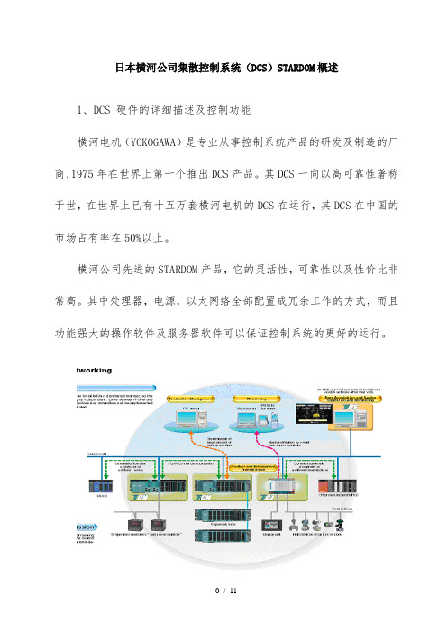
日本横河公司集散控制系统(DCS)STARDOM概述1、DCS 硬件的详细描述及控制功能横河电机(YOKOGAWA)是专业从事控制系统产品的研发及制造的厂商,1975年在世界上第一个推出DCS产品。
其DCS一向以高可靠性著称于世,在世界上已有十五万套横河电机的DCS在运行,其DCS在中国的市场占有率在50%以上。
横河公司先进的STARDOM产品,它的灵活性,可靠性以及性价比非常高。
其中处理器,电源,以太网络全部配置成冗余工作的方式,而且功能强大的操作软件及服务器软件可以保证控制系统的更好的运行。
STARDOM 系统结构图下面描述一个典型的STARDOM DCS系统的主要配置。
在这个实例中,5个分控站分别配置了5套最先进的STARDOM 系列控制站和操作站,其中控制站全部采用冗余的控制方式,即双控制器,双电源,双通讯卡,实现控制系统完全冗余,保证系统在主控制器发生故障时,无扰动的切换到后备控制器进行工作,而不会影响整个生产控制。
其中处理器选用FCN 控制器型号为NFCP100,CPU为32位处理器 , 内存 32M, 最大 I/O数:8,192 入 / 8,192 出数字量或 4000 模拟量, 支持冗余控制, 所有I/O模块可带电插拔, 配有CPU备用电池, 具有保护功能, 通讯接口:两个10BASET 的以太网端口,一个RS232 串口。
保证控制系统与操作站及中心控制室组成星型工业以太网进行通讯。
接地电阻要求100Ω以下,因此系统的抗干扰能力很强。
每个控制室配有二个带光纤接口的以太网交换机型号:S2008B 负责冗余以太网光纤通讯,每个交换机具有8个 RJ45端口,及一个光纤端口。
所有I/O卡件按照标书要求选用。
同时根据DCS控制系统的要求,我们配置了相应的DCS编程软件和操作软件VDS 以及中央控制室配有冗余监控软件VDS BASIC SOFTWARE 1000点和HMI CLIENT 软件支持服务器/客户端的工作方式;其中DCS I/O模块均符合标书中I/O的技术要求:DI:光电隔离、24VDC、每组16点、32点/卡DO:光电隔离、24VDC, 220VAC 继电器输出每组16点、32点/卡,5A 每通道,其中选用MIL (即连接器型的)NFDV551 DO输出卡和MRO224继电器输出板。
Yokogawa UM330 Temperature Meter用户手册说明书
Pr ec i s i o n p a ne li n st r u me n t a t i o n w i t h a n a lo g,d i gi t a l an d p u l s ei n p u t sf ori n d i c a t i o n ,d a t a i n t e r f a c eo r c o n t r o l •Selector GuidePLUG-IN OPTIONS¥Universal Power Supplies ¥Analog Outputs 0-20mADC and 0-10 VDC ¥Digital Interface: RS-232,RS-485, Modbus¥Dual Setpoint ControllerUNIVERSAL DIGITAL METER ¥DC Volts and Amps¥AC RMS Volts and Amps ¥Thermocouples and RTDs ¥Process Signals¥Strain Gauge and Load CellUNIVERSAL DIGITAL COUNTER¥Frequency and Period ¥Rate and Total¥Integration and Square Root ¥Quadrature and moreUM330PlusUNIVERSAL DIGITAL METERS & COUNTERSDC VOLTS and AMPSSelector GuideModel Format:Insert model code from the selection below:Basic DPM, display & power supply:List Price Green LED display, 85~264 VAC, 90~370 VDC ..................................................................$239.00 Green LED display, 8~28 VAC, 9~37 VDC ..........................................................................$269.00 Red LED display, 85~264 VAC, 90~370 VDC ....................................................................$239.00 Red LED display, 8~28 VAC, 9~37 VDC ............................................................................$269.00Output options:Adders None . . . . . . . . . . . . . . . . . . . . . . . . . . . . . . . . . . . . . . . . . . . . . . . . . . . . . . . . . . . . . . . . . .N/C Adjustable analog output range of 0-20 mA and 0-10 V . . . . . . . . . . . . . . . . . . . . . . . . .$90.00 Dual Form C, 8 Amp relays . . . . . . . . . . . . . . . . . . . . . . . . . . . . . . . . . . . . . . . . . . . . . .$80.00 Dual Form C, 8 Amp relays & analog output 0-20 mA and 0-10 V . . . . . . . . . . . . . . . .$170.00 Opto-Isolated open collectors . . . . . . . . . . . . . . . . . . . . . . . . . . . . . . . . . . . . . . . . . . . . .$60.00 Opto-Isolated open collectors & analog output 0-20 mA and 0-10 V . . . . . . . . . . . . . .$150.00Digital interface options:None........................................................................................................................N/C RS-232................................................................................................................$70.00 RS-485................................................................................................................$90.00 Modbus RS-485................................................................................................$100.00Input range options:200.00 mVDC ..............................................................................................N/C 2.0000 VDC ................................................................................................N/C 20.000 VDC ................................................................................................N/C 200.00 VDC ................................................................................................N/C 660.0 VDC ..................................................................................................N/C 2.000 mADC................................................................................................N/C 20.000 mADC..............................................................................................N/C 200.00 mADC..............................................................................................N/C 5.000 ADC ..................................................................................................N/COther Options:/BLKeyless faceplate. Specify meter range, scale, and legend information if desired with order information. . . . . . . . . . . . . . . . . . . . . . . . .$25.00Ordering Model Y821-00-0-DCV3 has red LED display with 8~28 VAC, 9~37 VDC power Example:and 20.000 VDC input range.The 800Plus Universal Digital Meter is a versatile, cost effective solution to a wide variety of monitoring and control applica-tions. The input can be changed by the user to any of the DC voltage and current values listed above by re-locatingshorting jumpers on the plug-in signal conditioner card. No calibration equipment is required when changing ranges since they are digitally precalibrated at the factory. Rescaling is accomplished via front panel pushbuttons. Optional alarms and outputs are also front panel programmable. Refer to product bulletin 800SP-A for complete specifications and descrip-tion of all features.800Plus3RMS VOLTS and AMPSSelector GuideModel Format:Insert model code from the selection below:Basic DPM, display & power supply:List Price Green LED display, 85~264 VAC, 90~370 VDC $239.00 Green LED display, 8~28 VAC, 9~37 VDC ..........................................................................$269.00 Red LED display, 85~264 VAC, 90~370 VDC ....................................................................$239.00 Red LED display, 8~28 VAC, 9~37 VDC ............................................................................$269.00Output options:Adders None . . . . . . . . . . . . . . . . . . . . . . . . . . . . . . . . . . . . . . . . . . . . . . . . . . . . . . . . . . . . . . . . . .N/C Adjustable analog output range of 0-20 mA and 0-10 V . . . . . . . . . . . . . . . . . . . . . . . . .$90.00 Dual Form C, 8 Amp relays . . . . . . . . . . . . . . . . . . . . . . . . . . . . . . . . . . . . . . . . . . . . . .$80.00 Dual Form C. 8 Amp relays & analog output 0-20 mA and 0-10 V . . . . . . . . . . . . . . . .$170.00 Opto-Isolated open collectors . . . . . . . . . . . . . . . . . . . . . . . . . . . . . . . . . . . . . . . . . . . . .$60.00 Opto-Isolated open collectors & analog output 0-20 mA and 0-10 V . . . . . . . . . . . . . .$150.00Digital interface options:None........................................................................................................................N/C RS-232 ..............................................................................................................$70.00 RS-485................................................................................................................$90.00 Modbus RS-485................................................................................................$100.00AC input:200.00 mVAC..........................................................................................$30.00 2.0000 VAC ............................................................................................$30.00 20.000 VAC ............................................................................................$30.00200.00 VAC ............................................................................................$30.00660.0 VAC ..............................................................................................$30.002.000 mAAC............................................................................................$30.0020.000 mAAC..........................................................................................$30.00 200.00 mADC..........................................................................................$30.005.000 AAC ..............................................................................................$30.00Other Options:/BLKeyless faceplate. Specify meter range, scale, and legend information if desired with order information. . . . . . . . . . . . . . . . . . . . . . . . .$25.00Ordering Model Y821-10-1-RMV5 has red LED display with 8~28 VAC, 9~37 VDC power,Example:dual 8A relay outputs, RS-232 digital interface and 660.0 VAC input range.The 800Plus Universal Digital Meter is a versatile, cost effective solution to a wide variety of monitoring and control applications. The input can be changed by the user to any of the RMS voltage or current values listed above by re-locating shorting jumpers on the plug-in signal conditioner card. No calibration equipment is required when changing ranges since they are digitally precalibrated at the facto-ry. Rescaling is accomplished via front panel pushbuttons. Optional alarms and outputs are also front panel programmable. Refer to product bulletin 800SP-A for complete specifications and description of all features.800Plus4RTD and THERMOCOUPLESelector GuideModel Format:Insert model code from the selection below:Basic DPM, display & power supply:List Price Green LED display, 85~264 VAC, 90~370 VDC . . . . . . . . . . . . . . . . . . . . . . . . . . . . . . . . . $239.00 Green LED display, 8~28 VAC, 9~37 VDC . . . . . . . . . . . . . . . . . . . . . . . . . . . . . . . . . . . . . $269.00 Red LED display, 85~264 VAC, 90~370 VDC . . . . . . . . . . . . . . . . . . . . . . . . . . . . . . . . . . $239.00 Red LED display, 8~28 VAC, 9~37 VDC . . . . . . . . . . . . . . . . . . . . . . . . . . . . . . . . . . . . . . $269.00Output options:Adders None . . . . . . . . . . . . . . . . . . . . . . . . . . . . . . . . . . . . . . . . . . . . . . . . . . . . . . . . . . . . . . . . . .N/C Adjustable analog output range of 0-20 mA and 0-10 V . . . . . . . . . . . . . . . . . . . . . . . . .$90.00 Dual Form C, 8 Amp relays . . . . . . . . . . . . . . . . . . . . . . . . . . . . . . . . . . . . . . . . . . . . . .$80.00 Dual Form C. 8 Amp relays & analog output 0-20 mA and 0-10 V . . . . . . . . . . . . . . . .$170.00 Opto-Isolated open collectors . . . . . . . . . . . . . . . . . . . . . . . . . . . . . . . . . . . . . . . . . . . . .$60.00 Opto-Isolated open collectors & analog output 0-20 mA and 0-10 V . . . . . . . . . . . . . .$150.00Digital interface options:None........................................................................................................................N/C RS-232 ..............................................................................................................$70.00 RS-485................................................................................................................$90.00 Modbus RS-485................................................................................................$100.00Temperature Type:Pt100 Ohm RTD DIN -202 to 850¡C............................................................N/C Pt100 Ohm RTD DIN -331 to 1562¡F ..........................................................N/C Pt100 Ohm RTD ANSI -202 to 850¡C..........................................................N/C Pt100 Ohm RTD ANSI -331 to 1562¡F ........................................................N/C J Thermocouple -210 to 760¡C....................................................................N/C J Thermocouple -347 to 1400¡F..................................................................N/C K Thermocouple -244 to 1372¡C ................................................................N/C K Thermocouple -408 to 2501¡F..................................................................N/C T Thermocouple -257 to 400¡C....................................................................N/C T Thermocouple -430 to 752¡F....................................................................N/C E Thermocouple -240 to 1000¡C ................................................................N/C E Thermocouple -400 to 1830¡F..................................................................N/C S Thermocouple -46 to 1768¡C ..................................................................N/C S Thermocouple -51 to 3213¡F....................................................................N/C R Thermocouple -45 to 1768¡C ..................................................................N/C R Thermocouple -49 to 3214¡F....................................................................N/COther Options:/BLKeyless faceplate. Specify meter range, scale, and legend information if desired with order information. . . . . . . . . . . . . . . . . . . . . . .$25.00Ordering Model Y821-10-1-RMV5 has red LED display with 8~28 VAC, 9~37 VDC power,Example:dual 8A relay outputs, RS-232 digital interface and 660.0 VAC input range.The 800Plus Universal Digital Meter inputs can be changed by the user to any of the RTD or thermocouple values listed above by re-locating shorting jumpers on the plug-in signal conditioner card. No calibration equipment is required. Refer to product bulletin 800SP-A for complete specifications and description of all features.800Plus5PROCESS INPUTS, LOAD CELL, Selector GuideSTRAIN GAUGEModel Format:Insert model code from the selection below:Basic DPM, display & power supply:List Price Green LED display, 85~264 VAC, 90~370 VDC ..................................................................$239.00Green LED display, 8~28 VAC, 9~37 VDC ..........................................................................$269.00Red LED display, 85~264 VAC, 90~370 VDC ....................................................................$239.00Red LED display, 8~28 VAC, 9~37 VDC ............................................................................$269.00Output options:Adders None . . . . . . . . . . . . . . . . . . . . . . . . . . . . . . . . . . . . . . . . . . . . . . . . . . . . . . . . . . . . . . . . . .N/C Adjustable analog output range of 0-20 mA and 0-10 V . . . . . . . . . . . . . . . . . . . . . . . . .$90.00 Dual Form C, 8 Amp relays . . . . . . . . . . . . . . . . . . . . . . . . . . . . . . . . . . . . . . . . . . . . . .$80.00 Dual Form C. 8 Amp relays & analog output 0-20 mA and 0-10 V . . . . . . . . . . . . . . . .$170.00 Opto-Isolated open collectors . . . . . . . . . . . . . . . . . . . . . . . . . . . . . . . . . . . . . . . . . . . . .$60.00 Opto-Isolated open collectors & analog output 0-20 mA and 0-10 V . . . . . . . . . . . . . .$150.00Digital interface options:None........................................................................................................................N/C RS-232 ..............................................................................................................$70.00 RS-485................................................................................................................$90.00 Modbus RS-485................................................................................................$100.00Signal Input:Process monitor 4-20 mADC = 0-10000 on display ....................................N/C Process monitor with custom scaling (specify input/display)*..................$20.00Strain gauge (4 wire ratio) 0 to 200 mV = 0 to 20000..................................N/C Strain gauge w/custom scaling (specify inputs/display rdgs)*..................$20.00Load cells (6 wire ratio) specify inputs/display rdgs/excitation*................$55.00Other Options:/BLKeyless faceplate. Specify meter range, scale, and legend information if desired with order information. . . . . . . . . . . . . . . . . . . . . . . . .$25.00Ordering Model Y811-10-1-P1 has green LED display with 8~28 VAC, 9~37 VDC power,Example:dual 8A relay outputs, RS-232 digital interface and customer specified input range of 4-20 mADC = 0 to 1600.0 on display*Specify input/display requirements (include excitation for load cells). If the requirment can be provided the/Jxx number will be assigned prior to entry of the order.The 800PlusUniversal Digital Meter is a versatile, cost effective solution to a wide variety of monitoring and con-trol applications. The input can be changed by the user to other values within each signal input category above by re-locating shorting jumpers on the plug-in signal conditioner card. No calibration equipment is required when changing ranges since they are digitally precalibrated at the factory. Rescaling is accomplished via front panel pushbuttons. Optional alarms and outputs are also front panel programmable. Refer to product bulletin 800SP-A for complete specifications and description of all features.6800PlusFREQUENCY, RATE, TOTAL, TIMERSelector GuideModel Format:Counter, display & power supply:List Price Basic counter, green LED display, 85~264 VAC, 90~370 VDC............................................$277.00 Basic counter, green LED display, 8~28 VAC,9~37 VDC ....................................................$309.00 Basic counter, red LED display, 85~264 VAC,90~370 VDC ................................................$277.00 Basic counter, red LED display, 8~28 VAC, 9~37 VDC........................................................$309.00Extended counter, green LED display, 85~264 VAC, 90~370 VDC......................................$320.00 Extended counter, green LED display, 8~28 VAC,9~37 VDC ..............................................$352.00 Extended counter, red LED display, 85~264 VAC,90~370 VDC ..........................................$320.00 Extended counter, red LED display, 8~28 VAC, 9~37 VDC ................................................$352.00Output options:Adders None . . . . . . . . . . . . . . . . . . . . . . . . . . . . . . . . . . . . . . . . . . . . . . . . . . . . . . . . . . . . . . . . . .N/C Adjustable analog output range of 0-20 mA and 0-10 V . . . . . . . . . . . . . . . . . . . . . . . . .$96.00 Dual Form C, 8 Amp relays . . . . . . . . . . . . . . . . . . . . . . . . . . . . . . . . . . . . . . . . . . . . . .$86.00 Dual Form C, 8 Amp relays & analog output 0-20 mA and 0-10 V . . . . . . . . . . . . . . . .$182.00 Opto-Isolated open collectors . . . . . . . . . . . . . . . . . . . . . . . . . . . . . . . . . . . . . . . . . . . . .$64.00 Opto-Isolated open collectors & analog output 0-20 mA and 0-10 V . . . . . . . . . . . . . .$160.00Digital interface options:None........................................................................................................................N/C RS-232................................................................................................................$75.00 RS-485................................................................................................................$96.00 Modbus RS-485................................................................................................$107.00Counter inputs:AC, pulses from transistors, contact closures, magn. pickup ......................N/C Analog to frequency converter (4-20 mA)....................................................N/C Analog to frequency converter (0-1 mA)......................................................N/C Analog to frequency converter (0-10 V)........................................................N/C Analog to frequency converter (special range-contact factory)........................CF Differential or single-ended inputs from quadrature encoders ..................$43.00Other Options:/BLKeyless faceplate. Specify meter range, scale, and legend information if desired with order information. . . . . . . . . . . . . . . . . . . . . . . . .$27.00Ordering ModelY 861-20-0-FR has red LED display with 8~28 VAC, 9~37 VDC power,Example:open collector output and dual channel counter/timer function.7800PlusNote: Refer to product bulletin 800SP-A for complete details and specifications.PEAK DISPLAY KEY In the Operating Mode, pressing the Peak Display Key causes the peak value of the input signal to be displayed. Pressing the key again returns the display to the present value. In Menu Mode ,the Digit Select Key (Peak Display Key) is used to select input type and decimal point or to select one of the five display dig-its for programming. In the main menu, pressing the Digit Select Key causes the value or code that is stored for that menu item to be displayed and the left hand digit flashes. Each time the key is pressed, the next digit to the right will flash. The value of the flash-ing digit may be changed using the Value Select Key. In the Alarm Mode, pressing the Digit Select Key causes the most sig-nificant digit of the displayed set-point value to flash. Digits are then selected the same as in the RESET KEY (VALUE SELECT)In the Operating Mode, holding the Reset Key depressed and pressing any other key causes a reset to occur. The Menu Key resets all meter functions, the Alarm Key resets any alarm conditions and the Peak Display Key resets the peak value to present value. In the MenuMode or Alarm Mode, the Value Select Key (Reset Key) sets the value of the flashing digit. Each time the key is pressed, the value increases by one. Holding the key down causes the digit to automatically step through the numbers.ALARM KEY(REVERSE MENU)In the Operating Mode, pressing the Alarm Key displays the set-point of Alarm 1 and then Alarm 2.These values may bechanged using the Digit Select Key and the Value Select Key. In the Menu Mode, pressing the Alarm Key steps the display backward through the menu.The menu key steps through the various meter parameters that may be selected.These menu items may be “locked out”selection by software Front Panel Setup KeysMounting PawlConnectorsThe 800Plus Universal Digital Meter uses UL/VDE ratedscrew terminal connections that plug into the mating PC jack.J1J2J3J4J510mm (.394in.)Mounting PawlRepresented by:96mm /BL Keyless Faceplate option。
Yokogawa

Yokogawayokogawa-横河电机―dcs系统―centumvp综合生产控制系统2022-04-2611:08:21 |分类:DCS过程控制技术|字体订阅工业快速的变化带来的不仅仅是技术上的进步,更主要的是帮助人们全面完成工作。
作为首个dcs,即centum的开发者,我们用了超过30年的时间关注工厂管理者、工程师和控制室操作员的反馈。
我们很自豪地向您推荐新世纪VP,作为开发的下一步,它将带来更好的信息可视化、性能预见性和操作警觉性。
我们希望你每天下班回家时都能有一种成就感。
简单而通用的架构简单通用的架构覆盖多种工厂规模和多个行业。
支持windowsvista的dcs系统操作站(his)基于windows的操作系统,商用成品pc硬件,以及用于多种操作台的可选专用操作员键盘。
工程师站(英文)与上述pc性能相同,包括用于所有工厂环境的全面工程软件包。
现场控制站(FCS)100%横河电机制造。
它是centumvp高可用性/可靠性的核心,继承了centum的优势。
控制局域网(Vnet/IP)vnet/ip,运行在1gbps的符合ieee802.3以太网的冗余网络,与横河电机的技术相结合,实现确定、可靠、安全的通信。
数字现场网络centumvp支持foundation?fieldbus,hart,profibus-dp,devicenet,modbus,modbus/tcp和ethernet/ip。
总线转换器(BCV)连接多个控制网络的接口硬件。
它可将之前的centum系列系统连接到centumvp。
生产优化软件包用于windows平台的软件套包支持工厂生产和维护的改进,如工厂安全、工厂资产管理、生产管理和最优化。
系统集成opc站(sios)它用于centumvp系统和其他公司的过程控制系统(PCS)之间的集成。
安全控制站(SCS)-ProSafe RS基于网络的系统控制器stardom直观HMIcentumvp采用新型人机界面(hmi),使信息访问更加快速直观。
YOKOGAWA YTA70 温度变送器 说明书

4
IM 01C50C03-01C-C
■ 尺寸
3
4
+-
6 5
φ6 (0.24)
单位: mm (英寸近似值)
φ 44 (1.73)
3
+-
1
2
33 (1.30)
20.2 (0.80)
7. 安全许可 7.1 CENELEC ATEX(DEMCO) 本安型(/KS2, /DS2)
[ 安装图 ]
危险场所
非危险场所
F04E.EPS
5
IM 01C50C03-01C-C
7.2 FM 本安型(/DS2)
安装图
[ 接收器内置电源连接 ]
I级 A,B,C,D组
危险场所
YTA70
非危险场所
安全栅 见注1,2
接收器 内置电源
[ 接收器和电源分离的连接 ]
I级 A,B,C,D组
危险场所
YTA70
非危险场所
安全栅 见注1,2
360
50
90
50
90
75
135
200
360
200
360
10
18
10
18
2.5 [mV]
25 [Ω]
精度 (以较大值为准) 量程的±0.1%或±1.0°C
量程的±0.1%或±0.5°C
量程的±0.1%或±1.0°C
量程的±0.1%或±0.5°C
量程的±0.1%或±1.0°C 量程的±0.1%或±0.1°C 量程的±0.1%或±0.2°C 量程的±0.1%或±0.01 mV 量程的±0.1%或±0.1Ω
输入导线电阻 (对热电阻输入) 每根5Ω或更小
出错 高(NAMUR NE43 upscale), 低(NAMUR NE43 downscale) 或 3.5 ~ 20 mA间的值
日本横河系列仪表

2-9-32,Nakacho,Musashino-shi, 东京都武藏野市中町2-9-32
横河电机(中国)商贸有限公司
地址: 中国上海市徐汇区淮海中路1010号嘉华中心(K.WAH CENTRE)28层~29层 邮编: 200031 电话: 021-54051515 传真: 021-54051011 地址: 北京市东城区金宝街89号金宝大厦9层 邮编: 100005 电话:010-85221155 传真:010-85221613 办事处:西安,惠州,苏州,南通,重庆,广州
用于高精度(ห้องสมุดไป่ตู้0.1%)温度控制的UT300系列
用于环境测试装置
高精度、五位数显示的UT551
红绿彩显
大数字测量值显示部分,绿 红彩 显自动切换!状态一目了然。
报警连动
测量值连动
偏差值连动
绿色/红色可固定
正常
UT321/UT351
自动/手动切换运行模式
UT351可直接连接以太网
UP351
两种编程模式
((只只44限8限8cc本h本h 体体))
最最快快2255mmss
1122年年连(连(66续c续chh记)记) 录录
更大
DX1000
2ch/4ch:125ms(高速模式时:25ms)
中中文拼文拼音音对对输输入入应应
方方便便!!!! 简简单单!!!! 6ch/12ch:1s(高速模式时:125ms)
外部存储使用CF卡最大可达2GB。 (标配32MB的CF卡。)
多功能电表通用三相3线式单相2线式单相3线式和三相3线式通用三相4线式通用电压输入110v220v440v1a通用电压输入110v220v440v5a数字输入1点数字输入1点模拟输出1点数字输入1点脉冲输出1点数字输入1点模拟输出1点脉冲输出1点rs485通信rs485通信ethernet通信需量测量需量报警接点输出1点100v240vacdcrst显示abc显示通常为0型号pr300相线额定输入电压电流附加输入输出功能通信功能附加测量功能辅助电源相位显示方式基本规格代码340大数字三段显示使用方便多功能电表高精度025pr300登场
yokogawa示波器的用法(一)
yokogawa示波器的用法(一)Yokogawa示波器的用法1. 什么是Yokogawa示波器Yokogawa示波器是一种用于显示和测量电信号波形的仪器。
它广泛应用于电子工程、通信技术、自动化控制等领域。
2. 基本操作打开示波器•按下示波器的电源按钮,等待示波器开机。
•如果示波器有多个通道,选择要使用的通道。
连接示波器探头•将示波器探头插入示波器的探头接口。
•将探头的夹子夹在被测电路上,确保良好的连接。
设置水平和垂直缩放•使用水平缩放按钮或旋钮,调整水平缩放,使波形适合屏幕显示。
•使用垂直缩放按钮或旋钮,调整垂直缩放,使波形适合屏幕显示。
设置触发方式•使用示波器面板上的触发按钮或菜单,选择触发方式,如边沿触发、脉冲触发等。
•根据需要设置触发电平、触发边沿等参数。
扫描并显示波形•单击示波器面板上的扫描按钮或触发按钮,示波器将开始扫描并显示被测电路的波形。
•观察波形并记录或分析所需的数据。
3. 高级功能自动测量功能•使用示波器面板上的自动测量按钮或菜单,示波器将自动测量波形的各种参数,如频率、幅度、相位等。
存储和回放波形•使用示波器的存储功能,将当前波形保存到示波器的内存或外部存储介质中。
•使用示波器的回放功能,可以随时回放已保存的波形,并进行进一步分析或比较。
远程控制功能•如果示波器支持远程控制功能,可以通过计算机或其他设备远程控制示波器。
•使用远程控制命令或软件,可以实现自动化测试和数据采集。
4. 注意事项•在操作示波器时,注意安全,确保与被测电路的正确连接,避免触电或电路损坏。
•遵循示波器的使用手册中的操作指南,以确保正确的操作和测量准确性。
•定期校准和维护示波器,以保证其性能和精度。
以上是一些Yokogawa示波器的用法介绍。
根据具体型号和功能,示波器可能有其他的特殊用法和功能,请参考示波器的使用手册获取更多详细信息。
yokogawa示波器的用法
yokogawa示波器的用法摘要:1.引言2.Yokogawa 示波器的基本概念3.Yokogawa 示波器的使用方法4.Yokogawa 示波器的应用实例5.结论正文:1.引言示波器是一种用于观察和测量电信号的电子仪器。
在众多示波器品牌中,Yokogawa 示波器凭借其卓越的性能和实用的功能,受到了广大工程师和技术人员的喜爱。
本文将为您介绍Yokogawa 示波器的使用方法,帮助您更好地掌握这一重要测试工具。
2.Yokogawa 示波器的基本概念Yokogawa 示波器是一种高性能的数字存储示波器,具有多种测量功能,如波形观测、数据记录、频谱分析等。
它具有较高的垂直分辨率和水平分辨率,能够精确地显示和测量信号。
此外,Yokogawa 示波器还具有友好的用户界面,使得操作更加便捷。
3.Yokogawa 示波器的使用方法(1)连接电路在使用Yokogawa 示波器之前,首先需要将待测电路与示波器连接。
通常情况下,需要将电路的输出端通过一根信号线连接到示波器的输入端。
此外,如果需要进行交流测量,还需要将电路的地线与示波器的地线相连。
(2)设置示波器参数连接好电路后,需要根据实际需求设置示波器的参数。
Yokogawa 示波器提供了丰富的参数设置选项,包括通道选择、触发模式、测量范围等。
在设置参数时,需要确保设置的参数与待测信号的特性相匹配,以保证测量结果的准确性。
(3)观察波形参数设置完成后,可以开始观察波形。
Yokogawa 示波器能够实时显示信号的波形变化,并通过屏幕上的标尺和网格线,帮助用户快速读取信号的幅度和周期等关键信息。
此外,还可以通过示波器的数据记录功能,将波形数据保存到计算机中,以便进行进一步的分析。
(4)测量信号在观察波形的基础上,还可以对信号进行详细的测量。
Yokogawa 示波器提供了多种测量工具,如垂直标尺、水平标尺、自动测量等。
通过这些工具,可以精确地测量信号的幅度、频率、相位等关键参数。
yokogawa示波器的用法
yokogawa示波器的用法
横河(Yokogawa)示波器是一种用于观察电信号波形的仪器。
以下是一般性的Yokogawa 示波器的基本使用方法:
1.连接电缆:将您要观察的电信号通过测试夹或探头连接到示波器的输入通道。
确保连接是正确的,避免损坏示波器或测试设备。
2.打开示波器:按下示波器的电源按钮,等待示波器启动。
有些示波器可能需要一些时间来进行初始化。
3.设置水平和垂直参数:使用示波器面板上的旋钮和按钮设置水平和垂直参数。
水平参数包括时间/分度、触发级别等,而垂直参数包括电压/分度、耦合方式等。
这些参数将帮助您更清晰地查看波形。
4.触发设置:设置触发条件,确保示波器以您期望的方式捕捉波形。
触发条件通常包括触发级别、触发边沿等。
5.选择显示模式:选择您想要显示的波形模式,例如实时模式或单次触发模式。
6.启动示波器:按下示波器面板上的启动按钮,开始捕捉和显示波形。
7.分析波形:使用示波器面板上的测量工具和功能,例如峰值测量、频率测量等,以分析波形特征。
8.保存数据:如果需要,示波器通常提供保存波形数据的选项,可以在后续分析中使用。
9.关闭示波器:使用示波器面板上的关闭按钮关闭示波器,确保设备安全关机。
请注意,具体的步骤和功能可能会根据您使用的横河示波器型号而有所不同。
建议参考您所使用示波器的用户手册以获取更详细的信息。
YOKOGAWA电导率
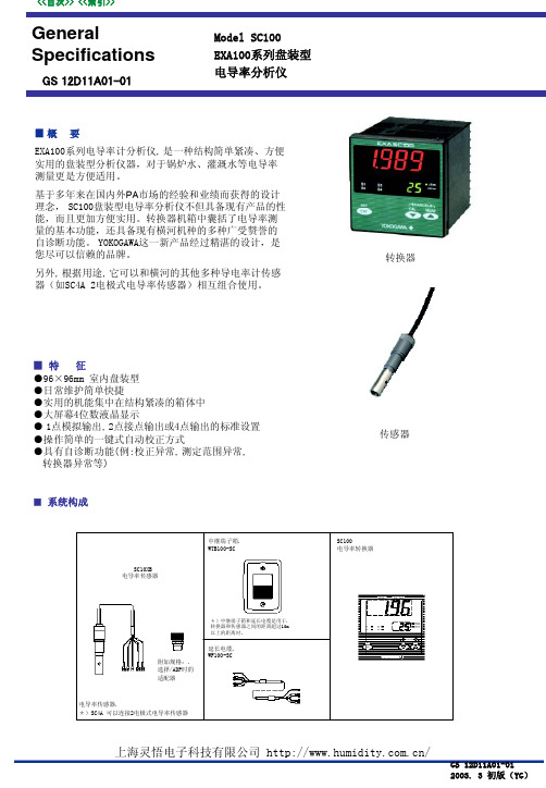
转换器背面图
延長ケーブル WF100SC
中继端子箱 WTB100-SC
C1 C2 S
屏蔽电缆
T1 T2 输出信号
D种接地(接地电阻100Ω以下)
導電率検出器 SC10XB SC100専用検出器
<SC100和SC4A的情况下>
接点输出1(NC) 接点输出1(NO)
规格
EXA100シリーズ専用延長ケーブル
SC100用 电缆长度 5m 电缆长度 10m 电缆长度 15m 电缆长度 20m 电缆长度 25m 电缆长度 30m 电缆长度 35m 电缆长度 40m 电缆长度 45m
■外部配线图
转换器・传感器・中继端子箱配线图
<SC100和SC10XB的情况下>
接点输出1(NC) 接点输出1(NO)
FAIL(异常)时输出信号:Downscale burnout(2 mA) S4(接点输出4点指定时) 开 闭 闭 开 闭 开 可选择 「有/无」
接点输出: 接点形式:继电器1接点输出 接点点数:2点或4点(在购买时请指定) 接点操作:ON/OFF 节电种类:可从上限警报,下限警报,上上限警报,
COM的最大负载电流是3A
传感器(SC10XB,SC4A)的最大量程为,0~2.0 mS/cm。
表示方式:液晶显示(LED) 表示范围:0.000μS/cm ~ 200.0 mS/cm
接点状态:
表示项目:导电率值,设定值,状态表示,温度表示 (温度表示范围:-10~110℃) 测定输入信号 导电率输入范围: 最小输入值:5μS/cm*K (K:cell定数)
注)与SC4A 2电极式电导率传感器组合使用的状况下,
请参照GS12D08F03。
2. SC100专用传感器 型号名称:SC10XB
yokogawa示波器的用法
yokogawa示波器的用法(最新版)目录1.概述2.Yokogawa 示波器的基本功能3.Yokogawa 示波器的操作方法4.Yokogawa 示波器的使用技巧5.总结正文1.概述Yokogawa 示波器是一种广泛应用于电子工程领域的测试仪器,它能够用于观察和测量电信号的波形、幅度、频率等特性,对于信号发生器、放大器、滤波器等电子设备的调试和检测具有重要作用。
2.Yokogawa 示波器的基本功能Yokogawa 示波器具有以下基本功能:(1)波形观察:能够实时显示输入信号的波形,方便工程师观察信号的特性。
(2)幅度测量:可以测量信号的幅度,即信号的峰值和有效值。
(3)频率测量:可以测量信号的频率,对于周期性信号,可以直接读取频率。
(4)相位测量:可以测量信号的相位,对于周期性信号,可以通过观察波形来读取相位。
3.Yokogawa 示波器的操作方法(1)连接电路:将待测信号的输入端连接到示波器的输入端,将示波器接地。
(2)打开示波器:开启示波器电源,等待示波器预热后,按下“开始”按钮开始测量。
(3)调整示波器:根据需要,调整示波器的触发方式、测量范围、显示模式等参数。
(4)读取数据:观察示波器屏幕上的波形和数值,读取需要的数据。
(5)保存数据:将测量得到的数据保存到电脑或其他存储设备中,以便后续分析。
4.Yokogawa 示波器的使用技巧(1)选择合适的示波器:根据待测信号的特性,选择具有合适测量范围和分辨率的示波器。
(2)正确连接电路:确保电路连接正确,避免由于接线错误导致的测量误差。
(3)合理设置参数:根据测量需求,合理设置示波器的各项参数,以提高测量精度。
(4)注意信号干扰:避免示波器与其他电子设备产生干扰,影响测量结果。
- 1、下载文档前请自行甄别文档内容的完整性,平台不提供额外的编辑、内容补充、找答案等附加服务。
- 2、"仅部分预览"的文档,不可在线预览部分如存在完整性等问题,可反馈申请退款(可完整预览的文档不适用该条件!)。
- 3、如文档侵犯您的权益,请联系客服反馈,我们会尽快为您处理(人工客服工作时间:9:00-18:30)。
在项目下(project)有一公共项common
S1:操作员级别
S2:班长级别
S3:工程师级别
User sec:用户级别
Operation mark:操作标记
Inst lable:定义字符标志
3.FCS控制功能定义(必须在用户自定义下才能用)IOM(node的建立)和删除
4.操作和监视
如下图所示,主要作为登陆时是否直接激活CS3000的操作画面。
2.2、Project’s Attribution Utility
当应用于现场控制时,必须为当前属性
2.3、Report package
应用于报表
2.3、system view
组态运用
3、第一次运行组态(system view)
第一次进入system view的时候,需要组态一个默认项目,默认项目的内容都选择默认的设置,不影响以后组态的运行。
3.1.1PFCS/PFCD
内存后备:72hour
I/O模块箱:2个/5个
AI/AO:128点
DI/DO:512点
双重化:CPU,电源
0 1
ODD
party Parity of the domain number(1bit)(odd parity)
0
Fixed to 0 (2bit)
0
MSB
Domain number (5bits)
0
Parity of the domain number (1bit.odd pornit)
MSB:most significant bit(高信号位)
LSB:least significant bit(低信号位)
拨号方式(domain)
2.2.3操作员键盘
三、FCS硬件构成
3.1FCS的类型
紧凑型
※在组态默认的过程中有两点注意的地方,一是项目的名字必须是字母大写;二是项目信息必须填写,或以空格代替,不能什么都不写,什么都不做,否则,后续工作就无法开展。
※需要提醒的是,CS3000是基于WINDOWS2000上的一个DCS系统,也有两点需要注意的地方,一是在不是WINDOWS2000系统上安装的时候也能安装,但无法激活CS3000系统,不能进行仿真测试,也无法调出操作画面;二是CS3000中的组态或文件删除必须在CS3000下进行,不能在WINDOWS中操作,否则导致系统无法运行,出现无法预料的错误。
AAI135—S(8点带隔电流输入)
AAR181—S(12点RTD输入,带隔离)
AAR145—S(16点RTD/POT通道隔离输入)
AAT141—S(16点毫伏输入,带隔离)
AAT145—S(16点毫伏,带隔离通道输入)
AAI841—S(8输入输出电流)
AAI835—S(4输入输出,带隔离通道)
四、系统软件安装
在HIS中建立:
控制分组:如CG0001等,为显示比如PID或输入数字显示,8或16个。
流程分组(CR0001等)
流程总览OV0001
趋势TG0101等
5.虚拟测试无目标测试
6.下装项目,须把要下装的项目变成当前项目
顺序:先下装系统的公共项,再FCS,HIS。
FCS分为:离线下装,在F ile中有Download(CPU停)
project :举例:如在64站上建项目,在63站上组态->网络邻居->
FCS:TEST测试作好的东西,仿真测试能否完成所要求的功能,测试哪个站先选中所测试的站
HIS:TEST对操作站进行模拟测试
HELP:在组态时可查找相关的文件
2.工程作业流程
功能规格书
I/O清单:模拟量
数字量复杂回路->顺控---操作界面
ESB:扩展型串行背板总线
ER:增强型远传总线
FIO:输入/输出单元
NODE:节点。NODE分两种:本地,远程。
FCU指示灯的含义及站地址的设置。
HRDY-绿灯亮硬件自诊断正常。
RDY—绿灯,硬件软件正常
TRL—处理卡运行正常,绿灯运行,不亮后备
3.3 I/O卡件的类型和功能。
AAI141—S(16点电流输入)
通过总线适配器YCB147(单)/YCB149(双),总线中继器YNT521将YCB141与YCB111相连
传输距离:YCB111500M
YCB141185M
混合连接:YCB141+0.4*YCB111《185M
使用光纤及中继器YNT511和YNT521可以达到4KM和15KM
1.2.2Ethernet
5、提醒是否安装资料到硬盘,选是。
6、安装程序进行到95%时,会提醒安装资料盘,放入第二张光盘,资料盘。
7、安装完后会提醒安装媒体播放盘,此项选“否”
8、提醒安装EXCEL97,选确定;提醒安装ACROBAT阅读器,如果没有安装,可安装,如果安装了选“否”,在ACROBAT阅读器安装完后,一定记得到资料盘里安装FINDER,否则以后查找资料要麻烦一些。
相关数据:
最大连接设备:1条ER BUS线上最多连接4个远传NODE
传输速率:10MB/S
传输介质:YCB141/YCB311(同轴)
传输距离:YCB141185MYCB311500M
2、软件概述
安装完后,与一般WINDOWS程序一样,可从程序里进入,如下图所示:
下面介绍主要几个软件的应用:
2.1、HIS Utlity
CPU:pentium 300MHZ OR faster .
2.2.2VF701卡及地址
置于PCI槽上的控制总线接上,用于将PC与FCS通讯。
VF701卡地址:DIP开关。域名开关1->16个,站名开关1->24个
1 0
(LSB)
Domain number(5bits)
0
Fixed to 0 (2bits) (2-3位总是为0)
3.上机组态
(1)项目的确认:用户自定义属性
当前项目
虚拟项目
FCS的数量
HIS的数量
属性的查看,改变:开始->程序->centum->project Attribution utility->出现对话框->将my project改变->user defined project->点中所改的项目-change –current project..
4.1准备:
①、CS3000 CD-ROM,②、CS3000电子文档③、KEY-CODE软盘④、ID号
⑤、Win2000操作系统安装盘⑥、Microsoft excel 97或2000⑦、V网卡驱动软件
4.2常用软件包
E网2000自动完成,V网必须系统软件
4.3CS3000的软件内容:CS3000软件,V网卡驱动程序,CS3000的电子文档
LSB
1-16个。2、3位必须为0
3.1.2RIO总线型FCS—LFCS
RIO:远程输入/输出总线
FCU分两种:机柜型架装型
NODE分两种:标准型机柜,19-inch架装型
机柜型型号:ANS20/AND20
架装型型号:ANS50/AND20
3.1.3FIO总线型FCS—KFCS
FCU:现场控制单元
甲乙酮使用的为:AFS40D Duplexed Field Control Unit
1.2.4ESB BUS(用于FIO型)
I/O通讯总线,用于FCS处理器与本地NODE间的连接
相关数据
最大连接设备:10NODE/FCU
传输速率:128MB/S
传输介质:使用电缆YCB301
Байду номын сангаас传输距离:最大10M
1.2.5ER BUS(用于FIO型)
I/O通讯总线,用于FCS处理器与远程NODE间的连接
8.目标测试(带控制单元的测试)
9.设定和备份调整参数load->save FCS->turing parameter.
10.项目备份:我的电脑->CS3000(C盘)--eng->Bkproject->具体的须备份的项目(报表没有备份进去)
报表的备份:CS3000->HIS-SAVE->REPORT->源文件编译,下装后为master. HIS中可保存30天的数据(但必须在做报表时就有一个命令指定完成才行)
在线下装,一般是局部修改,在掉电之前须保存load-save FCS.Turn (CPU不停)
7.HIS setup(从顶菜单的目标进入)
Equalize在Referenced中必须指定到工程师站,否则不能下装。
Invert printing反转打印
Display:有全屏显示和窗口显示,或显示趋势报警的字符选择(没中文)
4、创建一个新项目(Projection)
文件->>新建->>PROJECT->>填写项目名字->>项目信息说明->>组态与现场相符的控制站->>组态操作站->>生成一个项目
选中该项目,在该项目下点鼠标右键,可创建新的控制站和操作站
5、工艺人员画面:
二、HIS硬件构成
2.1标准型HIS
HIS标准型有以下几种类型:
如K HACP(硬copy,把当前的画面卸下来)
MSGRE pDef顺控请求信息;上述功能可用,按功能键启动,而这是用顺控表触发的。
例:TIC1001.ALAM.HH | Y
%RQ0001.PV.H | Y
6.2、OPECONDEF内容包括:打印机定义、关闭数据
4.4安装顺序:
1.WIN2000的安装。
2.安装V网驱动程序
3.安装CS3000,必须将软盘同时插入。
2、将软盘插入软驱中,将安装光盘放如光驱中。
