H3C MSR系列路由器IPsec典型配置举例(V7)
H3C MSR系列路由器 IPSec配置
H3C-MSR路由器配置
H3C-MSR路由器配置路由器作为网络中的重要设备之一,扮演着连接不同网络、实现数据转发的关键角色。
H3C-MSR路由器作为一款功能强大、性能稳定的产品,被广泛应用于各种规模的网络中。
为了使H3C-MSR路由器能够正常工作并满足网络需求,正确的配置是至关重要的。
本文将详细介绍H3C-MSR路由器的配置方法,帮助用户快速上手。
一、基本配置1. 连接路由器首先,使用网线将H3C-MSR路由器的Console接口与计算机的串口相连。
然后,使用串口终端工具,如SecureCRT等,通过串口连接到路由器。
打开终端工具后,选择正确的串口号和波特率,确保与路由器连接成功。
2. 登录路由器成功连接到路由器后,输入登录用户名和密码,即可登录路由器的命令行界面。
默认的用户名为admin,密码为空。
为了提高安全性,建议用户在首次登录后立即修改密码。
3. 设定主机名在路由器命令行界面下,通过以下命令来为路由器设定一个主机名:configure terminalhostname <主机名>exit二、接口配置1. 配置接口IP地址为了使路由器能够与其他设备进行通信,需要为其配置IP地址。
假设要为接口GigabitEthernet 0/0/1配置IP地址为192.168.1.1,子网掩码为255.255.255.0,可以在命令行界面下执行以下命令:interface GigabitEthernet 0/0/1ip address 192.168.1.1 255.255.255.02. 配置接口描述接口描述功能可以使管理员更好地管理和识别各个接口。
为了对接口GigabitEthernet 0/0/1进行描述,可以使用以下命令:interface GigabitEthernet 0/0/1description <描述信息>3. 配置接口速率和双工模式根据网络需求和接口连接设备的性能要求,可以配置接口的速率和双工模式。
H3C v7版本 ipsec over gre配置指导
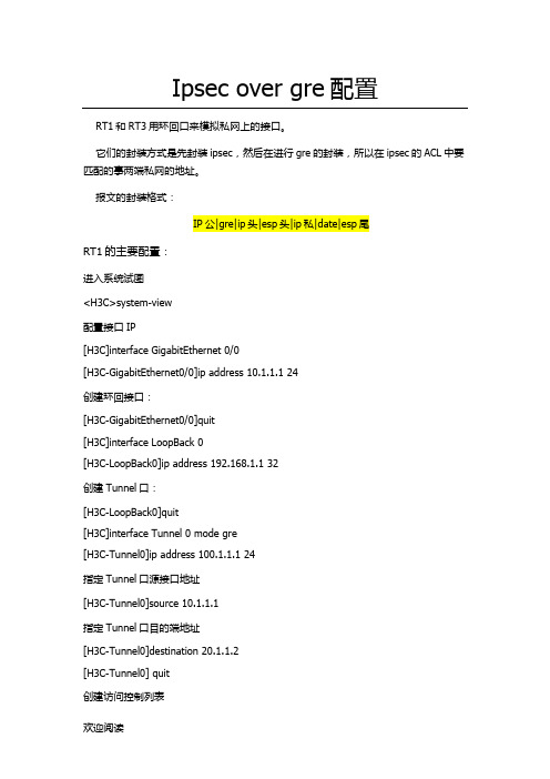
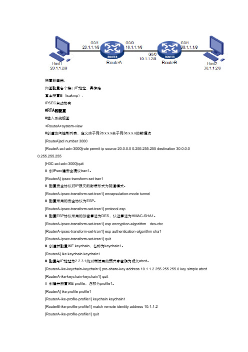
Ipsec over gre配置RT1和RT3用环回口来模拟私网上的接口。
它们的封装方式是先封装ipsec,然后在进行gre的封装,所以在ipsec的ACL中要匹配的事两端私网的地址。
报文的封装格式:指定Tunnel口源接口地址[H3C-Tunnel0]source 10.1.1.1指定Tunnel口目的端地址[H3C-Tunnel0]destination 20.1.1.2[H3C-Tunnel0] quit创建访问控制列表[H3C]acl advanced 3000[H3C-acl-ipv4-adv-3000]rule 0 permit ip source 192.168.1.1 0.0.0.0 destination 1 92.168.2.1 0.0.0.0[H3C-acl-ipv4-adv-3000]quit创建ipsec安全提议tran1[H3C]ipsec transform-set tran1指定安全协议的工作模式为隧道模式[H3C]ike profile profile1绑定ike keychain[H3C-ike-profile-profile1]keychain ike1配置本地封装的IP地址[H3C-ike-profile-profile1]local-identity address 100.1.1.1配置对端封装的IP地址[H3C-ike-profile-profile1]match remote identity address 100.1.1.2 24 [H3C-ike-profile-profile1]quit创建一条ike协商方式的ipsec安全策略,序列号为1,名字为policy1 [H3C]ipsec policy policy1 1 isakmp指定引用ACL3000[H3C-ipsec-policy-isakmp-policy1-1]security acl 3000[H3C-rip-1]network 10.1.1.1RT2的主要配置:<H3C>system-view[H3C]interface GigabitEthernet 0/0[H3C-GigabitEthernet0/0]ip address 10.1.1.2 24[H3C-GigabitEthernet0/0]quit[H3C]interface GigabitEthernet 0/1[H3C-GigabitEthernet0/1] ip address 20.1.1.1 24 [H3C-GigabitEthernet0/1]quit配置rip路由协议[H3C]rip[H3C-rip-1]version 2[H3C-rip-1]undo summary[H3C-rip-1]network 10.1.1.2指定Tunnel口源接口地址[H3C-Tunnel0]source 20.1.1.2指定Tunnel口目的端地址[H3C-Tunnel0]destination 10.1.1.1[H3C-Tunnel0] quit创建访问控制列表[H3C]acl advanced 3000[H3C-acl-ipv4-adv-3000]rule 0 permit ip source 192.168.2.1 0.0.0.0 destination 192.168.1.1 0.0.0.0[H3C-acl-ipv4-adv-3000]quit创建ipsec安全提议tran1[H3C]ipsec transform-set tran1指定安全协议的工作模式为隧道模式[H3C]ike profile profile1绑定ike keychain[H3C-ike-profile-profile1]keychain ike1配置本地封装的IP地址[H3C-ike-profile-profile1]local-identity address 100.1.1.2配置对端封装的IP地址[H3C-ike-profile-profile1]match remote identity address 100.1.1.1 24[H3C-ike-profile-profile1]quit创建一条ike协商方式的ipsec安全策略,序列号为1,名字为policy1[H3C]ipsec policy policy1 1 isakmp指定引用ACL3000[H3C-ipsec-policy-isakmp-policy1-1]security acl 3000[H3C-rip-1]network 20.1.1.2测试从RT1的环回口来ping RT3的环回口[H3C]ping -a 192.168.1.1 192.168.2.1Ping 192.168.2.1 (192.168.2.1) from 192.168.1.1: 56 data bytes, press CTRL_C to breakRequest time out56 bytes from 192.168.2.1: icmp_seq=1 ttl=255 time=2.000 ms56 bytes from 192.168.2.1: icmp_seq=2 ttl=255 time=2.000 ms 56 bytes from 192.168.2.1: icmp_seq=3 ttl=255 time=2.000 ms 56 bytes from 192.168.2.1: icmp_seq=4 ttl=255 time=1.000 ms 说明VPN建立成功。
HCMSR系列路由器IPsec典型配置举例V
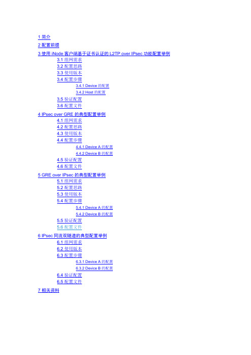
7 相关资料1 简介本文档介绍IPsec的典型配置举例。
2 配置前提本文档适用于使用Comware V7软件版本的MSR系列路由器,如果使用过程中与产品实际情况有差异,请参考相关产品手册,或以设备实际情况为准。
本文档中的配置均是在实验室环境下进行的配置和验证,配置前设备的所有参数均采用出厂时的缺省配置。
如果您已经对设备进行了配置,为了保证配置效果,请确认现有配置和以下举例中的配置不冲突。
本文档假设您已了解IPsec特性。
3 使用iNode客户端基于证书认证的L2TP over IPsec功能配置举例3.1 组网需求如图1所示,PPP用户Host与Device建立L2TP隧道,Windows server 2003作为CA服务器,要求:•通过L2TP隧道访问Corporate network。
•用IPsec对L2TP隧道进行数据加密。
•采用RSA证书认证方式建立IPsec隧道。
图1 基于证书认证的L2TP over IPsec配置组网图3.2 配置思路由于使用证书认证方式建立IPsec隧道,所以需要在ike profile中配置local-identity 为dn,指定从本端证书中的主题字段取得本端身份。
3.3 使用版本本举例是在R0106版本上进行配置和验证的。
3.4 配置步骤3.4.1 Device的配置(1) 配置各接口IP地址# 配置接口GigabitEthernet2/0/1的IP地址。
<Device> system-view[Device] interface gigabitethernet 2/0/1[Device-GigabitEthernet2/0/1] ip address 192.168.100.50 24[Device-GigabitEthernet2/0/1] quit# 配置接口GigabitEthernet2/0/2的IP地址。
[Device] interface gigabitethernet 2/0/2[Device-GigabitEthernet2/0/2] ip address 102.168.1.11 24[Device-GigabitEthernet2/0/2] quit# 配置接口GigabitEthernet2/0/3的IP地址。
H3C V7 MSR路由器 拨号上网配置 PPPoE配置示例之欧阳语创编

MSR路由器PPPoE配置示例1.2.配置示例图:3.PPPoE-Server配置:<PPPoE-Server>display current-configuration#version 7.1.075, Alpha 7571#sysnamePPPoE-Server#ip pool pppoe 121.48.47.2 121.48.47.6 //为PPPoE 客户端分配IP地址#dhcp enable#interface Virtual-Template1ppp authentication-mode pap domain system //客户端的验证方式remote address pool pppoe //指定为远端(PPPoE客户端)分配IP地址ip address 121.48.47.1 255.255.255.248dns server 8.8.8.8 //为对端分配DNS地址#interface NULL0#interface GigabitEthernet0/0port link-mode routecombo enable copperpppoe-server bind virtual-template 1 //应用到接口并绑定虚拟木模板1#domain systemauthentication ppp local //PPPoE认证方式为本地址认证#local-user pppoe class network //创建用于PPPoE 认证的本地用户password cipher pppoeservice-typeppp#Return4.PPPoE客户端配置:[PPPoE-Client]display current-configuration#version 7.1.075, Alpha 7571#sysnamePPPoE-Client#dialer-group 1 rule ip permit //定义拨号访问组1以及对应的拨号访问控制条件#dhcp enable#dhcp server ip-pool 1 //为内网用户分配IP地址gateway-list 192.168.100.254network 192.168.100.0 mask 255.255.255.0#interface Dialer 1 //配置拨号pppipcpdns admit-anypppipcpdns requestppp pap local-user pppoe password cipher pppoe dialer bundle enable //接口使能共享DDRdialer-group 1 //将Dialer 1接口与拨号访问组1关联dialer timer idle 0 //配置PPPoE Client 工作在永久在线模式(允许链路闲置的时间)dialer timer autodial 60 //配置DDR自动拨号的间隔时间为60秒ip address ppp-negotiate //配置接口从对端获得IP 地址nat outbound 2000 //配置NAT转换(内网用户通过NAT后才能访问公网)#interface GigabitEthernet0/0 //WAN口port link-mode routecombo enable copperpppoe-client dial-bundle-number 1 //配置PPPoE 会话#interface GigabitEthernet0/1 //LAN口port link-mode routecombo enable copperip address 192.168.100.254 255.255.255.0#ip route-static 0.0.0.0 0 Dialer1 //配置默认路由#acl basic 2000 //配置NAT过滤rule 5 permit#return。
H3CMSR系列路由器IPsec典型配置举例(V7)
7 相关资料1 简介本文档介绍IPsec的典型配置举例。
2 配置前提本文档适用于使用Comware V7软件版本的MSR系列路由器,如果使用过程中与产品实际情况有差异,请参考相关产品手册,或以设备实际情况为准。
本文档中的配置均是在实验室环境下进行的配置和验证,配置前设备的所有参数均采用出厂时的缺省配置。
如果您已经对设备进行了配置,为了保证配置效果,请确认现有配置和以下举例中的配置不冲突。
本文档假设您已了解IPsec特性。
3 使用iNode客户端基于证书认证的L2TP over IPsec功能配置举例3.1 组网需求如图1所示,PPP用户Host与Device建立L2TP隧道,Windows server 2003作为CA服务器,要求:•通过L2TP隧道访问Corporate network。
•用IPsec对L2TP隧道进行数据加密。
•采用RSA证书认证方式建立IPsec隧道。
图1 基于证书认证的L2TP over IPsec配置组网图3.2 配置思路由于使用证书认证方式建立IPsec隧道,所以需要在ike profile中配置local-identity 为dn,指定从本端证书中的主题字段取得本端身份。
3.3 使用版本本举例是在R0106版本上进行配置和验证的。
3.4 配置步骤3.4.1 Device的配置(1) 配置各接口IP地址# 配置接口GigabitEthernet2/0/1的IP地址。
<Device> system-view[Device] interface gigabitethernet 2/0/1[Device-GigabitEthernet2/0/1] ip address 192.168.100.50 24[Device-GigabitEthernet2/0/1] quit# 配置接口GigabitEthernet2/0/2的IP地址。
[Device] interface gigabitethernet 2/0/2[Device-GigabitEthernet2/0/2] ip address 102.168.1.11 24[Device-GigabitEthernet2/0/2] quit# 配置接口GigabitEthernet2/0/3的IP地址。
H3C V7 ipsec配置
配置路由器:如图配置各个接口IP地址,具体略基本配置B(isakmp):IPSEC自动协商#RTA的配置#进入系统视图<RouteA>system-view#创建访问控制列表,定义由子网20.x.x.x去子网30.x.x.x的数据流[RouteA]acl number 3000[RouteA-acl-adv-3000]rule permit ip source 20.0.0.0 0.255.255.255 destination 30.0.0.00.255.255.255[H3C-acl-adv-3000]quit# 创IPsec建安全提议tran1。
[RouterA] ipsec transform-set tran1# 配置安全协议对IP报文的封装形式为隧道模式。
[RouterA-ipsec-transform-set-tran1] encapsulation-mode tunnel# 配置采用的安全协议为ESP。
[RouterA-ipsec-transform-set-tran1] protocol esp# 配置ESP协议采用的加密算法为DES,认证算法为HMAC-SHA1。
[RouterA-ipsec-transform-set-tran1] esp encryption-algorithm des-cbc[RouterA-ipsec-transform-set-tran1] esp authentication-algorithm sha1[RouterA-ipsec-transform-set-tran1] quit# 创建并配置IKE keychain,名称为keychain1。
[RouterA] ike keychain keychain1# 配置与IP地址为2.2.3.1的对端使用的预共享密钥为明文abcd。
[RouterA-ike-keychain-keychain1] pre-share-key address 10.1.1.2 255.255.255.0 key simple abcd [RouterA-ike-keychain-keychain1] quit# 创建并配置IKE profile,名称为profile1。
IPSEC野蛮模式互通v7使用模板NAT
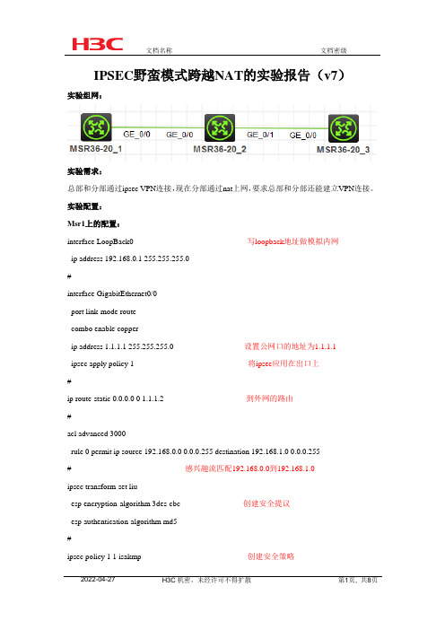
IPSEC野蛮模式跨越NAT的实验报告(v7)实验组网:实验需求:总部和分部通过ipsec VPN连接,现在分部通过nat上网,要求总部和分部还能建立VPN连接。
实验配置:Msr1上的配置:interface LoopBack0 写loopback地址做模拟内网ip address 192.168.0.1 255.255.255.0#interface GigabitEthernet0/0port link-mode routecombo enable copperip address 1.1.1.1 255.255.255.0 设置公网口的地址为1.1.1.1ipsec apply policy 1 将ipsec应用在出口上#ip route-static 0.0.0.0 0 1.1.1.2 到外网的路由#acl advanced 3000rule 0 permit ip source 192.168.0.0 0.0.0.255 destination 192.168.1.0 0.0.0.255# 感兴趣流匹配192.168.0.0到192.168.1.0ipsec transform-set liuesp encryption-algorithm 3des-cbc 创建安全提议esp authentication-algorithm md5#ipsec policy 1 1 isakmp 创建安全策略transform-set liu 绑定安全提议security acl 3000 绑定兴趣流remote-address 2.2.2.2 设置对端的地址ike-profile 1 引用profile#ike profile 1 配置profilekeychain 1exchange-mode aggressive 选择模式为野蛮模式local-identity fqdn rt1 定义本段的名字#ike keychain 1pre-shared-key address 2.2.2.2 255.255.255.0 key cipher$c$3$Qe9XOAQz1WG1gqfgpF2vhoMwNfA/Sw==MSR2上的配置:interface GigabitEthernet0/0port link-mode routecombo enable copperip address 1.1.1.2 255.255.255.0#interface GigabitEthernet0/1 在0/1口上设置NATport link-mode routecombo enable copperip address 2.2.2.1 255.255.255.0nat outboundMSR3上的配置:interface LoopBack0ip address 192.168.1.1 255.255.255.0 起loopback口模拟内网的地址#interface GigabitEthernet0/0port link-mode routecombo enable copperip address 2.2.2.2 255.255.255.0 在外网口上配置IP地址应用ipsecipsec apply policy 1#ip route-static 0.0.0.0 0 2.2.2.1 写出公网的路由ipsec transform-set liu 写安全提议esp encryption-algorithm 3des-cbcesp authentication-algorithm md5#ipsec policy-template 1 1 模板的方式互联transform-set liu 引用安全提议local-address 2.2.2.2 设置本端的地址ike-profile 1#ipsec policy 1 1 isakmp template 1 引用安全模板#ike profile 1keychain 1exchange-mode aggressivematch remote identity fqdn rt1#ike keychain 1 这里需要注意配置这个地址为nat设备的地址不能是私网的地址pre-shared-key address 2.2.2.1 255.255.255.255 key cipher$c$3$OyYvNspnlpcz0xEthe6KUIeuj+EwGw==实验成功分析[H3C]dis ipsec saInterface: GigabitEthernet0/0IPsec policy: 1Sequence number: 1Mode: ISAKMPTunnel id: 0Encapsulation mode: tunnel 封装模式为tunnelPerfect forward secrecy:Path MTU: 1435 传输单元为1435Tunnel:local address: 1.1.1.1 本端地址remote address: 2.2.2.2 对端地址Flow:sour addr: 192.168.0.0/255.255.255.0 port: 0 protocol: ipdest addr: 192.168.1.0/255.255.255.0 port: 0 protocol: ip [Inbound ESP SAs]SPI: 4286909264 (0xff850b50)Connection ID: 12884901889Transform set: ESP-ENCRYPT-3DES-CBC ESP-AUTH-MD5 一般排查故障的时候可以看两端Sa的加密方式是否一致SA duration (kilobytes/sec): 1843200/3600SA remaining duration (kilobytes/sec): 1843199/3219Max received sequence-number: 4Anti-replay check enable: YAnti-replay window size: 64UDP encapsulation used for NAT traversal: Y nat穿越开启Status: Active[Outbound ESP SAs]SPI: 1462729958 (0x572f7ce6)Connection ID: 21474836480Transform set: ESP-ENCRYPT-3DES-CBC ESP-AUTH-MD5SA duration (kilobytes/sec): 1843200/3600SA remaining duration (kilobytes/sec): 1843199/3219Max sent sequence-number: 4UDP encapsulation used for NAT traversal: YStatus: Active[H3C]dis ike sa verboseConnection ID: 3Outside VPN:Inside VPN:Profile: 1Transmitting entity: InitiatorLocal IP: 1.1.1.1Local ID type: FQDNLocal ID: rt1Remote IP: 2.2.2.2Remote ID type: IPV4_ADDRRemote ID: 2.2.2.2Authentication-method: PRE-SHARED-KEYAuthentication-algorithm: SHA1Encryption-algorithm: DES-CBCLife duration(sec): 86400Remaining key duration(sec): 85991Exchange-mode: AggressiveDiffie-Hellman group: Group 1NAT traversal: Detected在外网的路由器上的sa<H3C>dis ipsec saInterface: GigabitEthernet0/0IPsec policy: 1Sequence number: 1Mode: Template 模式是模板的方式Tunnel id: 0Encapsulation mode: tunnelPerfect forward secrecy:Path MTU: 1435Tunnel:local address: 2.2.2.2remote address: 2.2.2.1 可以看到这边是到对端公网口的地址,而不是内网口的地址Flow:sour addr: 192.168.1.0/255.255.255.0 port: 0 protocol: ipdest addr: 192.168.0.0/255.255.255.0 port: 0 protocol: ip[Inbound ESP SAs]SPI: 1462729958 (0x572f7ce6)Connection ID: 21474836481Transform set: ESP-ENCRYPT-3DES-CBC ESP-AUTH-MD5可是查看此验证是否一致SA duration (kilobytes/sec): 1843200/3600SA remaining duration (kilobytes/sec): 1843199/2936Max received sequence-number: 4Anti-replay check enable: YAnti-replay window size: 64UDP encapsulation used for NAT traversal: Y v7自动开启NAT穿越Status: Active[Outbound ESP SAs]SPI: 4286909264 (0xff850b50)Connection ID: 21474836480Transform set: ESP-ENCRYPT-3DES-CBC ESP-AUTH-MD5SA duration (kilobytes/sec): 1843200/3600SA remaining duration (kilobytes/sec): 1843199/2936Max sent sequence-number: 4UDP encapsulation used for NAT traversal: YStatus: Active<H3C>dis ike sa verbose-----------------------------------------------Connection ID: 8Outside VPN:Inside VPN:Profile: 1Transmitting entity: Responder-----------------------------------------------Local IP: 2.2.2.2Local ID type: IPV4_ADDRLocal ID: 2.2.2.2Remote IP: 2.2.2.1Remote ID type: FQDNRemote ID: rt1Authentication-method: PRE-SHARED-KEYAuthentication-algorithm: SHA1Encryption-algorithm: DES-CBCLife duration(sec): 86400 Remaining key duration(sec): 85712 Exchange-mode: AggressiveDiffie-Hellman group: Group 1 NAT traversal: Detected。
H3CMSR系列路由器IPsec典型配置举例(V7)
7 相关资料1 简介本文档介绍IPsec的典型配置举例。
2 配置前提本文档适用于使用Comware V7软件版本的MSR系列路由器,如果使用过程中与产品实际情况有差异,请参考相关产品手册,或以设备实际情况为准。
本文档中的配置均是在实验室环境下进行的配置和验证,配置前设备的所有参数均采用出厂时的缺省配置。
如果您已经对设备进行了配置,为了保证配置效果,请确认现有配置和以下举例中的配置不冲突。
本文档假设您已了解IPsec特性。
3 使用iNode客户端基于证书认证的L2TP over IPsec功能配置举例3.1 组网需求如图1所示,PPP用户Host与Device建立L2TP隧道,Windows server 2003作为CA服务器,要求:•通过L2TP隧道访问Corporate network。
•用IPsec对L2TP隧道进行数据加密。
•采用RSA证书认证方式建立IPsec隧道。
图1 基于证书认证的L2TP over IPsec配置组网图3.2 配置思路由于使用证书认证方式建立IPsec隧道,所以需要在ike profile中配置local-identity 为dn,指定从本端证书中的主题字段取得本端身份。
3.3 使用版本本举例是在R0106版本上进行配置和验证的。
3.4 配置步骤3.4.1 Device的配置(1) 配置各接口IP地址# 配置接口GigabitEthernet2/0/1的IP地址。
<Device> system-view[Device] interface gigabitethernet 2/0/1[Device-GigabitEthernet2/0/1] ip address 192.168.100.50 24[Device-GigabitEthernet2/0/1] quit# 配置接口GigabitEthernet2/0/2的IP地址。
[Device] interface gigabitethernet 2/0/2[Device-GigabitEthernet2/0/2] ip address 102.168.1.11 24[Device-GigabitEthernet2/0/2] quit# 配置接口GigabitEthernet2/0/3的IP地址。
H3C配置IPSEC教程实例介绍

H3C配置IPSEC教程实例介绍作为不同网络之间互相连接的枢纽,路由器系统构成了基于TCP/IP 的国际互联网络Internet 的主体脉络,也可以说,路由器构成了Internet的骨架。
这篇文章主要介绍了H3C配置IPSEC VPN教程实例(图文),需要的朋友可以参考下方法步骤H3C配置IPSEC VPN思路跟思科差不多,无非就是命令不一样的,下面就演示一下拓扑:RT1背后有个1.1.1.1网段,RT3背后有个3.3.3.3网段,ISP没有这两条路由RT2:system-viewSystem View: return to User View with Ctrl+Z.[RT2]int g0/0/0[RT2-GigabitEthernet0/0/0]ip add 12.1.1.2 24[RT2-GigabitEthernet0/0/0]quit[RT2]int g0/0/1[RT2-GigabitEthernet0/0/1]ip add 23.1.1.2 24[RT2-GigabitEthernet0/0/1]quitRT1:acl number 3000rule 0 permit ip source 1.1.1.0 0.0.0.255 destination 3.3.3.0 0.0.0.255ike proposal 1encryption-algorithm 3des-cbcauthentication-algorithm md5authentication-metod pre-sharedh group2ike peer ciscoid-type ippre-shared-key simple ciscoremote-address 23.1.1.3local-address 12.1.1.1#ipsec proposal ciscotransform espesp authentication-algorithm md5esp encryption-algorithm 3desipsec policy cisco 10 isakmpsecurity acl 3000ike-peer ciscoproposal ciscoint g0/0/0ipsec policy ciscoip route-static 0.0.0.0 0.0.0.0 12.1.1.2RT3:acl number 3000rule 0 permit ip source 3.3.3.0 0.0.0.255 destination 1.1.1.0 0.0.0.255ike proposal 1encryption-algorithm 3des-cbcauthentication-algorithm md5authentication-metod pre-sharedh group2ike peer ciscoid-type ippre-shared-key simple ciscoremote-address 12.1.1.1local-address 23.1.1.3#ipsec proposal ciscotransform espesp authentication-algorithm md5esp encryption-algorithm 3desipsec policy cisco 10 isakmpsecurity acl 3000ike-peer ciscoproposal ciscoint g0/0/1ipsec policy ciscoip route-static 0.0.0.0 0.0.0.0 23.1.1.2相关阅读:路由器安全特性关键点由于路由器是网络中比较关键的设备,针对网络存在的各种安全隐患,路由器必须具有如下的安全特性:(1)可靠性与线路安全可靠性要求是针对故障恢复和负载能力而提出来的。
H3C MSR系列路由器典型配置举例(V7)-6W100-整本手册
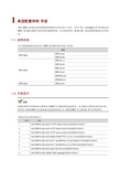
1 典型配置举例导读H3C MSR系列路由器典型配置举例(V7)共包括63个文档,介绍了基于Comware V7软件版本的MSR系列路由器软件特性的典型配置举例,包含组网需求、配置步骤、验证配置和配置文件等内容。
1.1 适用款型本手册所描述的内容适用于MSR系列路由器中的如下款型:款型MSR 5600 MSR 56-60 MSR 56-80MSR 3600 MSR 36-10 MSR 36-20 MSR 36-40 MSR 36-60 MSR3600-28 MSR3600-51MSR 2600 MSR 26-301.2 内容简介典型配置举例中特性的支持情况与MSR系列路由器的款型有关,关于特性支持情况的详细介绍,请参见《H3C MSR 系列路由器配置指导(V7)》和《H3C MSR 系列路由器命令参考(V7)》。
手册包含的文档列表如下:编号名称1H3C MSR系列路由器作为TFTP client升级版本的典型配置举例(V7)2H3C MSR系列路由器作为FTP client升级版本的典型配置举例(V7)3H3C MSR系列路由器作为FTP server升级版本的典型配置举例(V7)4H3C MSR系列路由器采用Boot ROM TFTP方式升级方法的典型配置举例(V7)5H3C MSR系列路由器内网用户通过NAT地址访问地址重叠的外网典型配置举例(V7)6H3C MSR系列路由器内网用户通过NAT地址访问内网服务器典型配置举例(V7)7H3C MSR系列路由器内部服务器负载分担典型配置举例(V7)8H3C MSR系列路由器NAT DNS mapping典型配置举例(V7)9H3C MSR系列路由器定时执行任务典型配置举例(V7)10H3C MSR系列路由器RBAC典型配置举例(V7)11H3C MSR系列路由器以太网链路聚合典型配置举例(V7)12H3C MSR系列路由器端口隔离典型配置举例(V7)13H3C MSR系列路由器VLAN典型配置举例(V7)14H3C MSR系列路由器QinQ典型配置举例(V7)15H3C MSR系列路由器PPP典型配置案例(V7)16H3C MSR系列路由器建立LAC-Auto-Initiated模式L2TP隧道典型配置举例(V7) 17H3C MSR系列路由器建立Client-Initiated模式L2TP隧道的典型配置举例(V7) 18H3C MSR系列路由器L2TP多实例典型配置举例(V7)19H3C MSR系列路由器L2TP多域接入典型配置举例(V7)20H3C MSR系列路由器L2TP over IPsec典型配置举例(V7)21H3C MSR系列路由器AAA典型配置举例(V7)22H3C MSR系列路由器802.1X本地认证典型配置举例(V7)23H3C MSR系列路由器802.1X结合Radius服务器典型配置举例(V7)24H3C MSR系列路由器IPsec典型配置举例(V7)25H3C MSR系列路由器Portal典型配置举例(V7)26H3C MSR系列路由器SSH典型配置举例(V7)27H3C MSR系列路由器OSPF典型配置举例(V7)28H3C MSR系列路由器IS-IS典型配置举例(V7)29H3C MSR系列路由器OSPFv3典型配置举例(V7)30H3C MSR系列路由器IPv6 IS-IS典型配置举例(V7)31H3C MSR系列路由器BGP基础典型配置举例(V7)32H3C MSR系列路由器路由策略典型配置举例(V7)33H3C MSR系列路由器策略路由典型配置举例(V7)34H3C MSR系列路由器Tcl脚本典型配置举例(V7)35H3C MSR系列路由器GRE和OSPF结合使用典型配置举例(V7)36H3C MSR系列路由器IPv6 over IPv4 GRE隧道典型配置举例(V7)37H3C MSR系列路由器ISATAP和6to4相结合使用的典型配置举例(V7)38H3C MSR系列路由器IPv6手动隧道+OSPFv3功能的典型配置举例(V7)39H3C MSR系列路由器授权ARP功能典型配置举例(V7)40H3C MSR系列路由器ARP防攻击特性典型配置举例(V7)41H3C MSR系列路由器ACL典型配置举例(V7)42H3C MSR系列路由器流量监管典型配置举例(V7)43H3C MSR系列路由器流量整形典型配置举例(V7)44H3C MSR系列路由器基于控制平面应用QoS策略典型配置举例(V7)45H3C MSR系列路由器IGMP Snooping典型配置举例(V7)46H3C MSR系列路由器IGMP典型配置举例(V7)47H3C MSR系列路由器组播VPN配置举例(V7)48H3C MSR系列路由器MPLS基础典型配置举例(V7)49H3C MSR系列路由器MPLS L3VPN典型配置举例(V7)50H3C MSR系列路由器HoVPN典型配置举例(V7)51H3C MSR系列路由器MPLS TE典型配置举例(V7)52H3C MSR系列路由器MPLS OAM典型配置举例(V7)53H3C MSR系列路由器作为重定向服务器反向Telnet的典型配置举例(V7)54H3C MSR系列路由器BFD典型配置举例(V7)55H3C MSR系列路由器VRRP典型配置举例(V7)56H3C MSR系列路由器SNMP典型配置举例(V7)57H3C MSR系列路由器Sampler结合IPv4 NetStream使用典型配置举例(V7)58H3C MSR系列路由器NQA典型配置举例(V7)59H3C MSR系列路由器EAA监控策略典型配置举例(V7)60H3C MSR系列路由器NTP典型配置举例(V7)61H3C MSR系列路由器RMON统计功能典型配置举例(V7)62H3C MSR系列路由器终端为流接入方式且应用为流连接方式典型配置举例(V7) 63H3C MSR系列路由器终端为TCP接入且应用为TCP连接方式典型配置举例(V7)H3C MSR系列路由器作为TFTP client升级版本的典型配置举例(V7)Copyright © 2014 杭州华三通信技术有限公司版权所有,保留一切权利。
H3C_MSR系列路由器典型配置举例(V7)-6W100-H3C_MSR系列路由器作为TFTP_client升级版本的典型配置举例(V7)

H3C MSR系列路由器作为TFTP client升级版本的典型配置举例(V7)Copyright © 2014 杭州华三通信技术有限公司版权所有,保留一切权利。
非经本公司书面许可,任何单位和个人不得擅自摘抄、复制本文档内容的部分或全部,并不得以任何形式传播。
本文档中的信息可能变动,恕不另行通知。
目录1 简介 (1)2 配置前提 (1)3 配置举例 (1)3.1 组网需求 (1)3.2 配置思路 (1)3.3 使用版本 (1)3.4 配置注意事项 (1)3.5 配置步骤 (2)3.5.1 Host的配置 (2)3.5.2 Router的配置 (2)3.6 验证配置 (4)3.7 配置文件 (5)4 相关资料 (5)1 简介本文档介绍使用TFTP方式升级集中式路由器软件版本的典型配置举例。
2 配置前提本文档适用于使用Comware V7软件版本的MSR系列路由器,如果使用过程中与产品实际情况有差异,请参考相关产品手册,或以设备实际情况为准。
本文档中的配置均是在实验室环境下进行的配置和验证,配置前设备的所有参数均采用出厂时的缺省配置。
如果您已经对设备进行了配置,为了保证配置效果,请确认现有配置和以下举例中的配置不冲突。
本文档假设您已了解TFTP的特性。
3 配置举例3.1 组网需求如图1所示,Host连接Router的GigabitEthernet0/0接口,Router作为TFTP客户端,Host作为TFTP 服务器。
现要求:通过TFTP方式为Router升级软件版本。
图1配置组网图3.2 配置思路为了使路由器在重启后使用新版本软件,需要指定下次启动时所用的主用启动文件为升级后的软件版本。
3.3 使用版本本举例是在R0106版本上进行配置和验证的。
3.4 配置注意事项•当设备剩余的存储空间不够,请使用delete /unreserved file-url命令删除部分暂时不用的文件后再执行升级软件操作。
华三无线v7简单配置案例
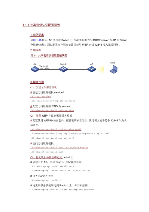
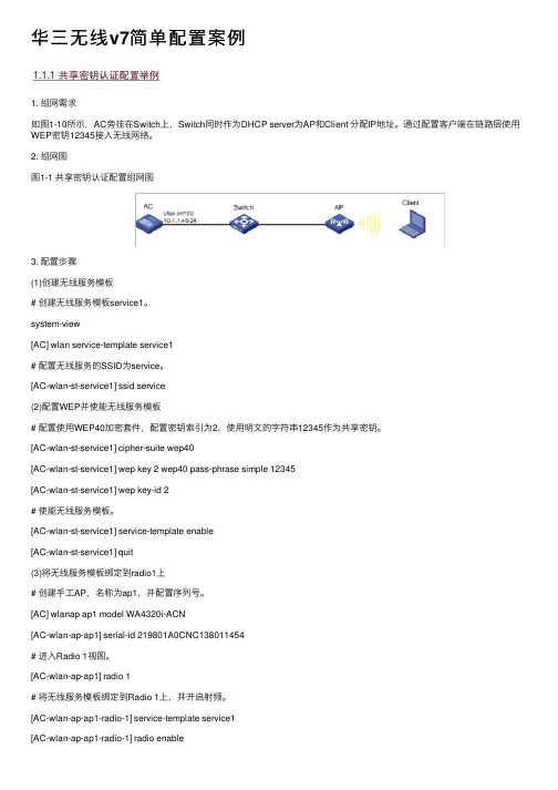
1. 组网需求如图1-10所示,AC旁挂在Switch上,Switch同时作为DHCP server为AP和Client 分配IP地址。
通过配置客户端在链路层使用WEP密钥12345接入无线网络。
2. 组网图图1-1 共享密钥认证配置组网图3. 配置步骤(1)创建无线服务模板# 创建无线服务模板service1。
<AC> system-view[AC] wlan service-template service1# 配置无线服务的SSID为service。
[AC-wlan-st-service1] ssid service(2)配置WEP并使能无线服务模板# 配置使用WEP40加密套件,配置密钥索引为2,使用明文的字符串12345作为共享密钥。
[AC-wlan-st-service1] cipher-suite wep40[AC-wlan-st-service1] wep key 2 wep40 pass-phrase simple 12345[AC-wlan-st-service1] wep key-id 2# 使能无线服务模板。
[AC-wlan-st-service1] service-template enable[AC-wlan-st-service1] quit(3)将无线服务模板绑定到radio1上# 创建手工AP,名称为ap1,并配置序列号。
[AC] wlan ap ap1 model WA4320i-ACN[AC-wlan-ap-ap1] serial-id 219801A0CNC138011454# 进入Radio 1视图。
[AC-wlan-ap-ap1] radio 1# 将无线服务模板绑定到Radio 1上,并开启射频。
[AC-wlan-ap-ap1-radio-1] service-template service1[AC-wlan-ap-ap1-radio-1] radio enable[AC-wlan-ap-ap1-radio-1] return4. 验证配置# 配置完成后,在AC上执行display wlan service-template命令,可以看到无线服务模板下安全信息的配置情况如下:<AC> display wlan service-template service1Service template name : service1SSID : serviceSSID-hide : DisabledUser-isolation : DisabledService template status : EnabledMaximum clients per BSS : 64Frame format : Dot3Seamless roam status : Disabled Seamless roam RSSI threshold : 50 Seamless roam RSSI gap : 20VLAN ID : 1AKM mode : Not configuredSecurity IE : Not configuredCipher suite : WEP40WEP key ID : 2TKIP countermeasure time : 0PTK lifetime : 43200 secGTK rekey : EnabledGTK rekey method : Time-basedGTK rekey time : 86400 secGTK rekey client-offline : EnabledUser authentication mode : BypassIntrusion protection : DisabledIntrusion protection mode : Temporary-blockTemporary block time : 180 secTemporary service stop time : 20 secFail VLAN ID : Not configured802.1X handshake : Disabled802.1X handshake secure : Disabled802.1X domain : Not configuredMAC-auth domain : Not configuredMax 802.1X users : 4096Max MAC-auth users : 4096802.1X re-authenticate : DisabledAuthorization fail mode : OnlineAccounting fail mode : OnlineAuthorization : PermittedKey derivation : N/APMF status : DisabledHotspot policy number : Not configuredForwarding policy status : Disabled Forwarding policy name : Not configuredFT status : DisabledQoS trust : PortQoS priority : 0(2)配置身份认证与密钥管理模式为PSK模式、加密套件为CCMP、安全信息元素为WPA并使能无线服务模板# 配置AKM为PSK,配置PSK密钥,使用明文的字符串12345678作为共享密钥。
H3C V7 MSR路由器 拨号上网配置 PPPoE配置示例
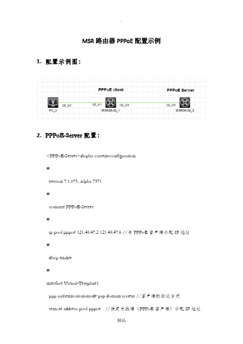
MSR路由器PPPoE配置示例1.配置示例图:2.PPPoE-Server配置:<PPPoE-Server>display current-configuration#version 7.1.075, Alpha 7571#sysname PPPoE-Server#ip pool pppoe 121.48.47.2 121.48.47.6 //为PPPoE客户端分配IP地址#dhcp enable#interface Virtual-Template1ppp authentication-mode pap domain system //客户端的验证方式remote address pool pppoe //指定为远端(PPPoE客户端)分配IP地址ip address 121.48.47.1 255.255.255.248dns server 8.8.8.8 //为对端分配DNS地址#interface NULL0#interface GigabitEthernet0/0port link-mode routecombo enable copperpppoe-server bind virtual-template 1 //应用到接口并绑定虚拟木模板1 #domain systemauthentication ppp local //PPPoE认证方式为本地址认证#local-user pppoe class network //创建用于PPPoE认证的本地用户password cipher pppoeservice-type ppp#Return3.PPPoE客户端配置:[PPPoE-Client]display current-configuration#version 7.1.075, Alpha 7571#sysname PPPoE-Client#dialer-group 1 rule ip permit //定义拨号访问组1以及对应的拨号访问控制条件#dhcp enable#dhcp server ip-pool 1 //为内网用户分配IP地址gateway-list 192.168.100.254network 192.168.100.0 mask 255.255.255.0#interface Dialer 1 //配置拨号ppp ipcp dns admit-anyppp ipcp dns requestppp pap local-user pppoe password cipher pppoedialer bundle enable //接口使能共享DDRdialer-group 1 //将Dialer 1接口与拨号访问组1关联dialer timer idle 0 //配置PPPoE Client 工作在永久在线模式(允许链路闲置的时间)dialer timer autodial 60 //配置DDR自动拨号的间隔时间为60秒ip address ppp-negotiate //配置接口从对端获得IP地址nat outbound 2000 //配置NAT转换(内网用户通过NAT后才能访问公网)#interface GigabitEthernet0/0 //WAN口port link-mode routecombo enable copperpppoe-client dial-bundle-number 1 //配置PPPoE会话#interface GigabitEthernet0/1 //LAN口port link-mode routecombo enable copperip address 192.168.100.254 255.255.255.0#ip route-static 0.0.0.0 0 Dialer1 //配置默认路由#acl basic 2000 //配置NAT过滤rule 5 permit#return如有侵权请联系告知删除,感谢你们的配合!。
H3C ipsec(V7---V5)

组网需求:MSR930为3G拨号上网,其获取到的为私网地址。
MSR36在NAT设备之后,其中在NAT设备上将MSR36的地址做一对一映射。
MSR930与MSR36做ipsec vpn。
MSR930配置:#version 5.20, Release 2511P02#sysname H3C-MSR930#ike local-name 3210#acl number 3000rule 0 deny ip source 172.16.1.0 0.0.0.255 destination 172.16.0.0 0.0.0.255rule 1000 permit ipacl number 3210rule 0 permit ip source 172.16.1.0 0.0.0.255 destination 172.16.0.0 0.0.0.255#vlan 1#vlan 1000#ike proposal 3210encryption-algorithm 3des-cbcauthentication-algorithm md5#ike peer 3210exchange-mode aggressive proposal 3210pre-shared-key simple 3210id-type nameremote-name v7remote-address 60.29.48.70nat traversal#ipsec transform-set 3210 encapsulation-mode tunnel transform espesp authentication-algorithm md5 esp encryption-algorithm des#ipsec policy 3210 1 isakmp security acl 3210ike-peer 3210transform-set 3210#interface Cellular1/0async mode protocollink-protocol pppppp chap user adminppp chap password cipher adminppp pap local-user admin password cipher admin ppp ipcp dns admit-anyppp ipcp dns requestip address ppp-negotiatedialer enable-circulardialer-group 1dialer timer idle 0dialer number *99# autodialnat outbound 3000ipsec no-nat-process enableipsec policy 3210#interface Vlan-interface1ip address 192.168.1.1 255.255.255.0#interface Vlan-interface1000ip address 172.16.1.1 255.255.255.0#interface GigabitEthernet0/1port link-mode bridgeport access vlan 1000#ip route-static 0.0.0.0 0.0.0.0 Cellular1/0MSR36配置:#version 7.1.042, Release 0007P02#sysname H3C-36-60#interface GigabitEthernet0/0port link-mode routecombo enable copperip address 192.168.10.67 255.255.255.0 nat outbound 3000ipsec apply policy 3210#interface GigabitEthernet0/1port link-mode routecombo enable copperip address 172.16.0.1 255.255.255.0#ip route-static 0.0.0.0 0 192.168.10.2#acl number 3000rule 0 deny ip source 172.16.0.0 0.0.0.255 destination 172.16.1.0 0.0.0.255 rule 1000 permit ip#acl number 3100rule 0 permit ip source 172.16.0.0 0.0.0.255 destination 172.16.1.0 0.0.0.255 #ipsec transform-set 11esp encryption-algorithm des-cbcesp authentication-algorithm md5#ipsec policy-template 1 3210transform-set 11security acl 3100ike-profile 11#ipsec policy 3210 1 isakmp template 1#ike identity fqdn v7#ike profile 11keychain 11exchange-mode aggressivelocal-identity fqdn v7match remote identity fqdn 3210proposal 11#ike proposal 11encryption-algorithm 3des-cbcauthentication-algorithm md5#ike keychain 11pre-shared-key hostname 3210 key cipher 3210注意:1.V5侧ike对等体中使用id-type name时,必须指名字remote-name2.V7 必须配置ipsec 模板才能不配置remote-address,如果使用ipsec policy 要么配置remote-address ip(前方的应用中不知道对方地址),要么必须配置remote-address hostname,而hostnmae还需要DNS 配合使用3.V7侧不用使能nat 穿越,V7自动检测nat 穿越。
华三无线v7简单配置案例
华三⽆线v7简单配置案例1. 组⽹需求如图1-10所⽰,AC旁挂在Switch上,Switch同时作为DHCP server为AP和Client 分配IP地址。
通过配置客户端在链路层使⽤WEP密钥12345接⼊⽆线⽹络。
2. 组⽹图图1-1 共享密钥认证配置组⽹图3. 配置步骤(1)创建⽆线服务模板# 创建⽆线服务模板service1。
system-view[AC] wlan service-template service1# 配置⽆线服务的SSID为service。
[AC-wlan-st-service1] ssid service(2)配置WEP并使能⽆线服务模板# 配置使⽤WEP40加密套件,配置密钥索引为2,使⽤明⽂的字符串12345作为共享密钥。
[AC-wlan-st-service1] cipher-suite wep40[AC-wlan-st-service1] wep key 2 wep40 pass-phrase simple 12345[AC-wlan-st-service1] wep key-id 2# 使能⽆线服务模板。
[AC-wlan-st-service1] service-template enable[AC-wlan-st-service1] quit(3)将⽆线服务模板绑定到radio1上# 创建⼿⼯AP,名称为ap1,并配置序列号。
[AC] wlanap ap1 model WA4320i-ACN[AC-wlan-ap-ap1] serial-id 219801A0CNC138011454# 进⼊Radio 1视图。
[AC-wlan-ap-ap1] radio 1# 将⽆线服务模板绑定到Radio 1上,并开启射频。
[AC-wlan-ap-ap1-radio-1] service-template service1[AC-wlan-ap-ap1-radio-1] radio enable[AC-wlan-ap-ap1-radio-1] return4. 验证配置# 配置完成后,在AC上执⾏display wlan service-template命令,可以看到⽆线服务模板下安全信息的配置情况如下:display wlan service-template service1Service template name : service1SSID : serviceSSID-hide : DisabledUser-isolation : DisabledService template status : EnabledMaximum clients per BSS : 64Frame format : Dot3Seamless roam status : Disabled Seamless roam RSSI threshold : 50 Seamless roam RSSI gap : 20VLAN ID : 1AKM mode : Not configuredSecurity IE : Not configuredCipher suite : WEP40WEP key ID : 2TKIP countermeasure time : 0PTK lifetime : 43200 secGTK rekey : EnabledGTK rekey method : Time-basedGTK rekey time : 86400 secGTK rekey client-offline : EnabledUser authentication mode : BypassIntrusion protection : DisabledIntrusion protection mode : Temporary-blockTemporary block time : 180 secTemporary service stop time : 20 secFail VLAN ID : Not configured802.1X handshake : Disabled802.1X handshake secure : Disabled802.1X domain : Not configuredMAC-auth domain : Not configuredMax 802.1X users : 4096Max MAC-auth users : 4096802.1X re-authenticate : DisabledAuthorization fail mode : OnlineAccounting fail mode : OnlineAuthorization : PermittedKey derivation : N/APMF status : DisabledHotspot policy number : Not configuredForwarding policy status : Disabled Forwarding policy name : Not configured FT status : DisabledQoS trust : PortQoS priority : 0(2)配置⾝份认证与密钥管理模式为PSK模式、加密套件为CCMP、安全信息元素为WPA并使能⽆线服务模板# 配置AKM为PSK,配置PSK密钥,使⽤明⽂的字符串12345678作为共享密钥。
H3C MSR系列路由器典型配置举例(V7)-6W100-H3C MSR系列路由器BGP基础典型配置举例(V7)

3.1 组网需求 ··············································································································································· 1 3.2 配置思路 ··············································································································································· 1 3.3 使用版本 ··············································································································································· 1 3.4 配置注意事项········································································································································ 2 3.5 配置步骤 ··············································································································································· 2
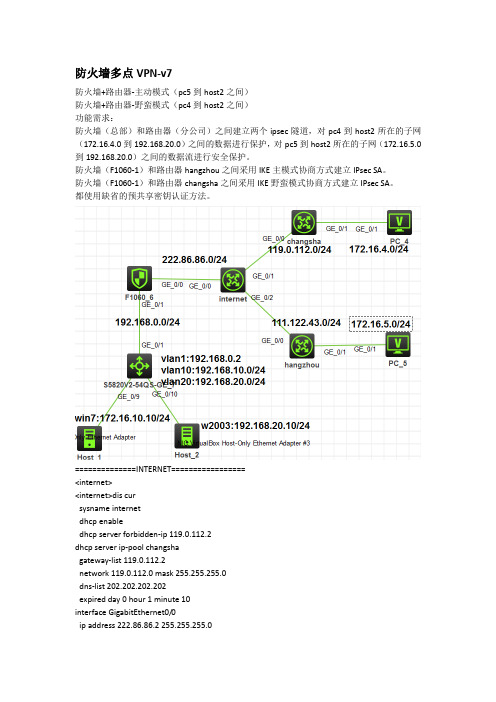
H3C防火墙到路由器多点VPN-v7
<sw>
<sw>dis vlan brief
Brief information about all VLANs:
Supported Minimum VLAN ID: 1
Supported Maximum VLAN ID: 4094
transform-set changsha_set
security acl 3002
local-address 222.86.86.1
ike-profile changsha
#
ipsec policy-template hangzhou_tmp 20
transform-set hangzhou_set
dhcp server forbidden-ip 119.0.112.2
dhcp server ip-pool changsha
gateway-list 119.0.112.2
network 119.0.112.0 mask 255.255.255.0
dns-list 202.202.202.202
interface GigabitEthernet1/0/0
ip address 222.86.86.1 255.255.255.0
ipsec apply policy firewall_policy
#
interface GigabitEthernet1/0/1
ip address 192.168.0.1 255.255.255.0
security-zone name Local
#
security-zone name Trust
- 1、下载文档前请自行甄别文档内容的完整性,平台不提供额外的编辑、内容补充、找答案等附加服务。
- 2、"仅部分预览"的文档,不可在线预览部分如存在完整性等问题,可反馈申请退款(可完整预览的文档不适用该条件!)。
- 3、如文档侵犯您的权益,请联系客服反馈,我们会尽快为您处理(人工客服工作时间:9:00-18:30)。
7 相关资料1 简介本文档介绍IPsec的典型配置举例。
2 配置前提本文档适用于使用Comware V7软件版本的MSR系列路由器,如果使用过程中与产品实际情况有差异,请参考相关产品手册,或以设备实际情况为准。
本文档中的配置均是在实验室环境下进行的配置和验证,配置前设备的所有参数均采用出厂时的缺省配置。
如果您已经对设备进行了配置,为了保证配置效果,请确认现有配置和以下举例中的配置不冲突。
本文档假设您已了解IPsec特性。
3 使用iNode客户端基于证书认证的L2TP over IPsec功能配置举例3.1 组网需求如图1所示,PPP用户Host与Device建立L2TP隧道,Windows server 2003作为CA服务器,要求:•通过L2TP隧道访问Corporate network。
•用IPsec对L2TP隧道进行数据加密。
•采用RSA证书认证方式建立IPsec隧道。
图1 基于证书认证的L2TP over IPsec配置组网图3.2 配置思路由于使用证书认证方式建立IPsec隧道,所以需要在ike profile中配置local-identity 为dn,指定从本端证书中的主题字段取得本端身份。
3.3 使用版本本举例是在R0106版本上进行配置和验证的。
3.4 配置步骤3.4.1 Device的配置(1) 配置各接口IP地址# 配置接口GigabitEthernet2/0/1的IP地址。
<Device> system-view[Device] interface gigabitethernet 2/0/1[Device-GigabitEthernet2/0/1] ip address 192.168.100.50 24[Device-GigabitEthernet2/0/1] quit# 配置接口GigabitEthernet2/0/2的IP地址。
[Device] interface gigabitethernet 2/0/2[Device-GigabitEthernet2/0/2] ip address 102.168.1.11 24[Device-GigabitEthernet2/0/2] quit# 配置接口GigabitEthernet2/0/3的IP地址。
[Device] interface gigabitethernet 2/0/3[Device-GigabitEthernet2/0/3] ip address 192.168.1.1 24[Device-GigabitEthernet2/0/3] quit(2) 配置L2TP# 创建本地PPP用户l2tpuser,设置密码为hello。
[Device] local-user l2tpuser class network[Device-luser-network-l2tpuser] password simple hello[Device-luser-network-l2tpuser] service-type ppp[Device-luser-network-l2tpuser] quit# 配置ISP域system对PPP用户采用本地验证。
[Device] domain system[Device-isp-system] authentication ppp local[Device-isp-system] quit# 启用L2TP服务。
[Device] l2tp enable# 创建接口Virtual-Template0,配置接口的IP地址为172.16.0.1/24。
[Device] interface virtual-template 0[Device-Virtual-Template0] ip address 172.16.0.1 255.255.255.0# 配置PPP认证方式为PAP。
[Device-Virtual-Template0] ppp authentication-mode pap# 配置为PPP用户分配的IP地址为172.16.0.2。
[Device-Virtual-Template0] remote address 172.16.0.2[Device-Virtual-Template0] quit# 创建LNS模式的L2TP组1。
[Device] l2tp-group 1 mode lns# 配置LNS侧本端名称为lns。
[Device-l2tp1] tunnel name lns# 关闭L2TP隧道验证功能。
[Device-l2tp1] undo tunnel authentication# 指定接收呼叫的虚拟模板接口为VT0。
[Device-l2tp1] allow l2tp virtual-template 0[Device-l2tp1] quit(3) 配置PKI证书# 配置PKI实体 security。
[Device] pki entity security[Device-pki-entity-security] common-name device[Device-pki-entity-security] quit# 新建PKI域。
[Device] pki domain headgate[Device-pki-domain-headgate] ca identifier LYQ[Device-pki-domain-headgate] certificate request url http://192.168.1.51/certsrv/mscep/mscep.dll [Device-pki-domain-headgate] certificate request from ra[Device-pki-domain-headgate] certificate request entity security[Device-pki-domain-headgate] undo crl check enable[Device-pki-domain-headgate] public-key rsa general name abc length 1024[Device-pki-domain-headgate] quit# 生成RSA算法的本地密钥对。
[Device] public-key local create rsa name abcThe range of public key modulus is (512 ~ 2048).If the key modulus is greater than 512,it will take a few minutes. Press CTRL+C to abort.Input the modulus length [default = 1024]:Generating Keys.............................++++++.++++++Create the key pair successfully.# 获取CA证书并下载至本地。
[Device] pki retrieve-certificate domain headgate caThe trusted CA's finger print is:MD5 fingerprint:8649 7A4B EAD5 42CF 5031 4C99 BFS3 2A99SHA1 fingerprint:61A9 6034 181E 6502 12FA 5A5F BA12 0EA0 5187 031CIs the finger print correct?(Y/N):yRetrieved the certificates successfully.# 手工申请本地证书。
[Device] pki request-certificate domain headgateStart to request general certificate ...Certificate requested successfully.(4) 配置IPsec隧道# 创建IKE安全提议。
[Device] ike proposal 1[Device-ike-proposal-1] authentication-method rsa-signature[Device-ike-proposal-1] encryption-algorithm 3des-cbc[Device-ike-proposal-1] dh group2[Device-ike-proposal-1] quit# 配置IPsec安全提议。
[Device] ipsec transform-set tran1[Device-ipsec-transform-set-tran1] esp authentication-algorithm sha1[Device-ipsec-transform-set-tran1] esp encryption-algorithm 3des[Device-ipsec-transform-set-tran1] quit# 配置IKE profile。
[Device] ike profile profile1[Device-ike-profile-profile1] local-identity dn[Device-ike-profile-profile1] certificate domain headgate[Device-ike-profile-profile1] proposal 1[Device-ike-profile-profile1] match remote certificate device[Device-ike-profile-profile1] quit# 在采用数字签名认证时,指定总从本端证书中的主题字段取得本端身份。
[Device]ike signature-identity from-certificate# 创建一条IPsec安全策略模板,名称为template1,序列号为1。
[Device] ipsec policy-template template1 1[Device-ipsec-policy-template-template1-1] transform-set tran1[Device-ipsec-policy-template-template1-1] ike-profile profile1[Device-ipsec-policy-template-template1-1] quit# 引用IPsec安全策略模板创建一条IPsec安全策略,名称为policy1,顺序号为1。