热保护器测试系统说明书
UL2111(中文版)
表格 7.1 最高温度
Motor insulation system Class A Class B Class F Class H
Maximu m temperature
EC
EF
150
302
175
347
200
392
225
437
7.6
根据制造商的要求,上面的测试在会造成电机绕组在表格 7.1 中所指出的绝缘等
含的热断路器。
1.4
本标准的要求是用来评估带有给定保护器的专门电机。当电机或者保护器改变
时,需要进行单独的评估。
1.5
产品包含的特征,特性,零部件,材料,或者系统跟本标准要求所覆盖的不一样
或者是没有被覆盖的,并且它们具有火灾,电击,或者人身伤害风险的,应该
根据需要使用合适的额外的零部件和最终产品要求来进行评估以使它们保持在
用较低热传导铝的固定平面上。
7.2
电容永久性分离的电机测试,应该在电容正确连接在电路上或者电容短路的情况 下
进行,取决于哪种情况下获得的温度最高。 例外 1:电容作为电机一个部件的并
且整体安装在电机里面的电机,不需要在电
容短路的情况下进行测试。
例外 2:带有通过 UL 810,电容器的标准的评估要求的电容器的电机,不需要 在电容短路的情况下进行测试。
5.4
变电阻法是采用比较线圈的热态电阻和室温时的电阻,然后使用下面的方程来确
定热态时线圈的温度:
T2=R2 (K% T1) & K/R1 在这里:
T2 是测试结束时以℃表示的线圈温度; R2是测试结束时线圈的电阻; R1是测试开始时线圈的电阻; 对于铜,K 取 234.5;对于导电铝导线,K 取 225;其他导线的 K 值 根 据情况确定;
远鸿电器 TM1系列热保护器 使用说明书
TM1 系列热保护器 产品使用说明书中山市远鸿电器有限公司(原广州宏拓电器)Zhongshan YuanHong electrical equipment Co., LTD2004年9月TM1 系列热保护器产品使用说明书一、主要用途和适用范围TM1系列热保护器是专门设计安装在电动机内或电动机上,以防止电动机过载运 行或起动失败而引起过热的自动控制器。
该控制器承载电动机的电流,而且对电动机 的温度和电流是敏感的或仅对温度敏感。
因此,该保护器还可用作热切断器,用在家 用和类似用途电器产品上防止电器设备产生过热,避免发生危及安全的事故。
该产品具有如下特点:1、过热保护功能保证电机在各种供电条件下输出额定功率而不引起热保护系统脱扣。
在电机 进行慢变化热过载(如稳定过载)和快变化热过载(如堵转)而脱扣时,任一被 保护部件不会达到对以后的使用有害的温度,而电机绕组的最高温度不超过最高 温度限值。
当用在家用电器和类似用途电器产品上时,保证被保护部件的最高温度不超 过最高温度限值。
2、快速动作,响应灵敏3、工作稳定,可靠性高4、接触电阻小5、体积小、安装方便6、动作特性重复性好TM1系列热保护器按照GB13232《旋转电机装入式热保护 热保护器通用规则》 和 GB/T13002《旋转电机装入式热保护 旋转电机的保护规则》标准的要求设计和制 造,并符合美国UL2111、UL873 和IEC730(EN60730)等国际标准的要求。
该系列产品适用于分马力电动机、家用和类似用途电器以及普通电气设备和器具 的过热保护。
例如:空调风扇电机、洗衣机电机、抽油烟机电机、变压器、日光灯镇 流器、电磁灶、微波炉等。
二、产品适用的工作条件和工作环境1、海拔:安装地点的海拔高度不超过2000m。
2、大气条件:安装地点最湿月的月平均最大相对湿度为90%,同时该月的月平均最低温度不高于25℃。
3、周围空气温度:安装地点的周围空气温度上限不超过 40℃,24h 平均值不超过35℃,下限不低于-5℃。
精创电器 TSG-10温度保护器说明书

设置指示灯
按下并松开SET键,显示设定的化霜高温保护值;按下并松开 键,显示设定的库温高温报警值;按下并松开 键,显示设定的库温低温保护值。
3秒后返回正常温度显示状态。
同时按SET键+ 键10秒以上进入菜单模式,显示第一个菜单项,同时菜单模式指示灯亮。
按 键或 键可上翻或下翻菜单项。
按FNC键3秒以上或15秒内无任何按键操作,则保存参数修改并返回正常温度显示
菜单模式下按SET键显示参数值,同时参数调整模式指示灯亮。
按 键或 键可调整参数值。
按SET键保存当前参数修改并显示下一个菜单项。
15秒内如无任何按键操作则保存参数修改并返回正常温度显示状态。
保护器处于锁定状态时,按SET键+FNC键10秒以上显示Pn,解除锁定并清除记录的保护次数。
3秒后返回正
查看及切换当前传感器:
保护器首次通电后默认显示化霜传感器温度。
按下FNC键并立即松开,显示当前传感器代码。
按FNC键3秒以上,可切换当前传感器并存储。
(化霜传感器代码dP,库温传感器代码rP。
)3秒后返回正常温度显示
1、严格区分传感器、电源及继电器输出引线,接线要牢靠,不可错接,继电器不可过荷;
2、所有的接线更改都必须在断开电源的情况下进行。
本产品禁止在水中或过度潮湿的环境中使用,禁止在高温、强电磁干扰、强腐蚀性环境中使用;。
BW-9700热保护器BW-9700SeriesThermalProtector…

BW-9700热保护器BW-9700 Series Thermal Protector结构特点Features or structureBW-9700系列热保护器是由碟形高灵敏双金属元件、动触头、静触片、固定底座、外壳、耐温导线等组成。
工作时双金属元件处于自由状态,动触头与静触片闭合,电路导通。
当使用电器因故障发热而使温度上升至热保护器的动作温度时,双金属元件受热产生内应力而迅速动作,推开动触头离开静触片而断开电路,从而切断故障电器电源起到保护电器作用。
当被保护电器温度下降到热保护器的额定复位温度值时,双金属元件恢复到初始状态触点闭合,电器恢复正常工作。
该产品具有电阻小、感温快、动作迅速、安全可靠、体积小等优点。
BW-9700 series thermal protector consists of dish shape high sensitive bimetallic elemeng,movable contact-head,static contact-piece,soleplate,outer case,ghermal resistant lead and so on.When operation,the bimetallic element is in free state and movable contact-head and static contace-piece are closed and the circuit is on.When the electric appliance is in operation is in operation and produces heat caused by some troubles and temperature is raised to the rated action temperature of the product,the bimetallic element produces inner stuess and acts quickly and pushes the movable contact-head and make the vontact point off and the power supply is rurned off the electric appliance stop.in this way the thermal protection is made.When the temperature of electric appliance to be protected is dropped to the rated reset temperature.The bimetallic element restores to its primary state and contact point is closed .The electric appliance restores its work.The product has many advantages such as small in resistor,puick in temperature feeling,fast in action.Safe and pact and so on.Drawing for working timeClosing condition before the action Disconnecting currentcondition after the action型号说明The model number explainBW-9700ABJ:金属外壳型产品The metals outer shell type product.BW-9700ABS:塑料外壳型产品The plastics outer shell type product.金属外壳型产品其外壳为带电体,应加装绝缘外套The metals outer shell type the product outer shell take an electricity, should add to insulate a coat.BW-9700热保护器BW-9700 Series Thermal Protector应用范围Product application适用于各种家用电器和电子产品。
RPT1266型继电保护测试系统使用说明书.doc

TP—1200微机继电保护测试仪使用说明书武汉拓普特电力自动化有限公司ﻬ前言继电保护测试装置是保证电力系统安全可靠运行的一种重要测试工具。
随着现代电力系统规模的不断扩大,对电力系统运行和管理的可靠性、高效性要求的不断提高,继电保护人员的测试工作变得更加频繁和复杂。
在计算机技术、微电子技术、电力电子技术飞速发展的今天,应用最新技术成果不断推出新型高性能继电保护测试仪是技术进步的必然趋势,也是时代赋予我们的责任。
TP-1200微机继电保护测试仪是在参照中华人民共和国电力行业标准《继电保护微机型试验装置技术条件》(DL/T 624 ─1997)的基础上,广泛听取用户意见,总结目前国内同类产品优缺点,充分使用现代先进的微电子技术和器件实现的一种新型小型化微机继电保护测试仪.它采用可单机独立运行,亦可联接其它电脑运行的先进结构,主机内置高性能工控机和高速数字信号处理器,真16位DAC模块、新型模块式高保真大功率功放,自带TFT真彩色LCD显示器和嵌入式微机键盘。
既可以单机独立操作,也可以连接笔记本电脑操作.操作功能强大,体积小,精度高。
既具有大型测试仪优越的性能、先进的功能,又具有小型测试仪小巧灵活、操作简便、可靠性高等优点,性能价格比高。
是继保工作者得心应手的好工具.ﻬ目录第一章继电保护测试仪说明 (5)1.1主要技术特点 (5)1.2主要技术指标 (6)1.3面板说明 (9)1.4硬件结构………………………………………………………101.5仪器的操作使用 (11)1.6注意事项………………………………………………………13第二章继电保护测试仪使用方法.................................15 2.1递变试验×7 (15)2.2递变试验×12 ………………………………………………202.3状态序列 (24)2.4谐波试验 (27)2.5整组试验………………………………………………………322.6差动保护试验.........................................................37 2.7频率试验 (43)2.8同期试验 (46)2.9电流—时间特性试验…………………………………………49 2.10电压-时间特性试验…………………………………………522.11故障再现………………………………………………………552.12距离保护试验.........................................................642.13零序保护试验 (69)2.14阻抗特性试验 (73)附录1:试验方法.........................................................78附录2:差动保护知识 (87)附录3:配置清单 (9)1附录4:售后服务 (92)ﻬ第一章继电保护测试仪说明1.1 主要技术特点微机型继电保护测试仪其主要特点表现为:经典的Windows XP操作界面,人机界面友好,操作简便快捷,为了方便用户使用,定义了大量键盘快捷键,使得操作“一键到位”;●高性能的嵌入式工业控制计算机和8。
电流型热保护器自动测试系统的设计

的特 性 来 改 变 导 电状 态 的保 护 器 ,而 当温 度 下 降 到 设 定 的工 作
温度 时 , 它又 能 恢 复 原 状 而重 新 接 通 电路 ; 类 是 R K 一 S Y型 双 保
险热 保 护 器 , 是 R 型热 熔 断体 和 R 它 Y S型 热 保 护 器 组 合 而 成 的
K y r ss p re tprt co , M, r e p a e AC c n t n u r n o r e e wod :u e h a oe t r P t e — h s o s a t c r t s u c I h e
热 保 护 器 又 称 过 载 保 护 器 , 冰 箱 、 调 的 压 缩 机 的过 载 、 是 空 堵转 和非 正 常 工作 而产 生 的过 热 过 程 的安 全 保 护 器 件 ,其 质 量
直接 影 响 到 整 机 的安 全 。目前 , 内 电流 型 热 保 护 器 的 检 测设 备 国 自动化 程 度 较 低 , 定 性 和 可靠 性 不 高 。 研 制 出 自动 化 程 度 高 、 稳 精度 高 的 电机 热保 护 器 检 测 设 备 具 有 比 较重 要 的实 际 意 义 。
2 自动 测试 系统 软 硬 件 设 计
IM ( tl e tP w rMo u ) 智 能 功 率 模 块 , 先 进 P I el n o e d l 即 n i g e 是
的 混 合 集 成 功 率 器 件 , 高 速 、 功 耗 的 l T芯 片 和 优 选 的 门 由 低 GB 级 驱 动 及 保 护 电路 构 成 。它 将 功率 器 件 l T全 部 集 成 在 一 个 GB 器件内 , 同时 它 对 分 立 的 驱 动 电路 进行 了优 化 , 驱 动 电路 和 保 将
热电缆系统产品说明书

Installation ManualFloor heating systemContentsImportant Safeguards and Warnings (3)1 General Information (3)1.1 Use of the Manual (3)1.2 Safety Guidelines (3)1.3 Remember to measure resistance (3)1.4 25-year Limited Warranty (3)2 Heat Cable System (4)2.1 Specifications (4)3 Floor Heating Design and Product Selection (4)3.1 Design the Installation (4)3.2 Cable Selection (5)4 Installation (6)5. Resistance Test (9)5.1 Insulation Resistance Test (9)5.2 Heating Cable Resistance Test (9)5.3 Sensor Resistance Test (9)6 Troubleshooting (10)EXTENDED WARRANTY (10)23Important Safeguards and WarningsWARNING: Shock and fire hazardIf the Heat Cable System is damaged or not installed properly, fire or shock could occur resulting in serious personal injuries or damage to property. You must carefully follow the warnings and instructions contained in this manual.· A qualified thermostat must be used.· It is important that this equipment is installed only by qualified electricians who are familiar with the proper sizing, installation, construction and operation of floor warming system and the hazards involved. The installation must comply with all national and local electrical codes. If you are unfamiliar with these requirements, contact an electrician.· The heating cable is designed for under floor heating purposes only. Be sure that the floor is not penetrated by nails, screws, or similar devices that can cause damage on first installation or during subsequent floor repairs in the future.· If the Heat Cable System is damaged, it must be replaced. Do not attempt to splice or repair any part of the system1 General Information1.1 Use of the ManualThis manual describes the Heat Cable floor heating system — how to design the room, select the product, and install the system. It is important to thoroughly review this manual and the following document prior to installation.Dr. Heater Thermostat Installation and Operation Manual1.2 Safety GuidelinesThe safety and reliability of any floor heating system depends on proper design, installation, and testing. Incorrect installation or mishandling of the product can cause damage to the heating cable, system components and property, and can create a risk of fire or shock. The guidelines and instructions contained in this guide are important. Follow them carefully to minimize these risks and to ensure that the Heat Cable system performs reliably.Pay special attention to the following: ·Instructions marked Important ·Safety warnings identified as WARNING1.3 Remember to measure resistanceThe resistance should be measured between the two conductors, white and black. Compare this resistance reading to the resistance specified in the Product Selection “Table 1 or Table 2”. The value should be within ±10%.Also, measure the resistance between the white, black and shielding/ground wire. Both should read infinity.Please refer to “5 Commissioning ” for instructions on how to measure the resistance.Important: measure the resistance four times during the installation process Remember to always measure, verify and record the actual resistance throughout the installation process (out of the box, after installation, after thin set cement or self-leveler application and after installation of floor tiles).1.4 25-year Limited WarrantyFor a period of twenty-five (25) years from the date of purchase Dr. Heater warrants that the heating cable is free from defects in material, design and workmanship. The warranty is only valid if the warranty certificate has been properly completed and mailed, and the installation is in accordance with the installation instructions.2 Heat Cable SystemImportant· Read the instructions carefully before installing Heat Cable system.· Remember to measure the resistance four times.· Do not install Heat Cable in walls or ceilings.· The cable must be embedded in mortar, thinset, concrete or similar material.· The minimum installation temperature is 40℉(5℃).· The heating cable cannot be cut to length, crossed over itself, or installed too close.· It is recommended to use copper wire only.· Remember to check that the supply voltage matches the voltage of the Heat Cable.· Remember to place the labels as written in this instruction.· Only for indoor installation.· Metal structures or materials used for the support of or on which the Heat Cable is installed must be grounded in accordance with CSA Standard C22.1, section 10 and the NEC.Please consult the factory for any other questions or advice.3 Floor Heating Design and Product Selection3.1 Design the InstallationStep 1: Measure the heated areaDetermine the heated area of the floor where there are no permanent fixtures or furniture such as showers, toilets, vanities, or cabinets. Measure the heated area of the floor.For example, in Figure 3, the area of the bathroom is 96 ft2. When you subtract the area of the vanity, shower and toilet, the total heated area is only 74 ft2.Step 2: Determine the power supply voltageThe available supply voltages include 120 V, 208 V or 240 V.ImportantOperating the 240V cable at 208V reduces the power output to approximately 2.25W/ft. (25% reduction) Step 3: Plan the designDetermine the optimum floor heating Cable layout for your heated area to ensure coverage. Select a spot for the thermostat in the wall above the heated area where it can be reached by the 10-foot cold lead on the Heat Cable, and the 10-foot floor temperature sensor. Please refer to Figure 4.ImportantThe predetermined Heat Cable spacing must be maintained to ensure proper floor heating. Do not change the heating cable spacing when you lay out the cable or the floor may have cold spots.453.2 Cable SelectionSelect an appropriate length of cable. The cable’s standard heating area (see table below) must be smaller than the actual area to be heated. Example: if the area to be heated is 74 ft 2, select the 70 ft 2 Heat Cable system.Table 1: 120V Product SelectionFigure 3: Measure and design the heated areaFigure 4: Typical cold lead and floor temperature sensor6Table 2: 240V Product Selection4 InstallationImportant: Tools and materials requiredYou will require the following items to install and test the floor heating system:·Scissors ·Utility knife ·Wire strippers ·Nail Plate ·Membrane or Metal strapping ·Tape measure ·Screwdriver ·MultimeterYou will also need the appropriate tools and materials to install your particular floor. These will likely include products like self-leveling mortar, thin-set mortar, backer board, tile, a notched trowel, and any other tools for your specific floor.Follow these steps to ensure a successful Heat Cable installation.Install with Membrane:Use a membrane like Schluter DITRA Membrane, Prodeso Heat Membrane, Warmup DCM membrane or other equivalent membranes.Schluter DITRA Membrane Prodeso Membrane Warmup Membrane7Step 1: PLAN LAYOUTMake a sketch layout or a floor plan of the room; include all permanent furnishings such as toilets, bathtubs, appliances, cabinetry, etc. Indicate all dimensions required to determine the available floor area and the position of the Dr. Heater thermostat. ImportantDr. Heater recommends that the installation is documented with photos to note the location of connections and the sensor.Step 2: TRANSFER LAYOUT TO FLOORDraw an outline of the layout on the room floor including a foot print of all furnishings that are not yet installed.Step 3: PREPARE SUBFLOOR SURFACEClean and vacuum the floor thoroughly and remove dust and debris from the floor that may damage the heating cable. Ensure that the subfloor is secure and stable. Carefully fill in all cracks to prevent any potential damage to the new tiles resulting from shifts in the subfloor.Step 4: LAYER THE MEMBRANEApply a compatible adhesive to the substrate using a suitable trowel. Cut the membrane for suitable size and uncoupling it. Lay the membrane on the adhesive. Press the membrane evenly with a roller or a plastic flat trowel. Check coverage of membrane, in case of partial coverage increase the amount of adhesive or its fluidity. Then lay the next sheet of membrane, making sure to align it with the previous one without overlapping. Align the square reliefs to facilitate the installation of the heating cables.Warning:If heavy mechanical loads are foreseen (frequent passages), it is recommended to protect the laid membrane with wooden planks to ensure proper bonding.Step 5: MEASURE THE RESISTANCE (THE FIRST TIME)Use a digital ohm meter to measure the resistance of the Heat Cable and compare it to “Table1 or Table 2”. Record the measured resistance on the warranty card. Documenting the resistance at each stage of installation is required for warranty purposes. Also, measure the resistance between the white, black and shielding/ground wire. Both should read infinity.Please refer to “5 Commissioning” for instructions on how to measure the resistance.Step 6: Start LAYING THE HEAT CABLEDO NOT RUN THE HEATING CABLES UNDER WALLS, CABINETS, FURNITURE AND APPLIANCES!8Place the cable so that the connection point and the temperature sensor are in their intended positions and bring the power lead cable to the thermostat or connection box.Begin laying the Heat Cable heating cable on membrane according to the layout developed in Step 1.DO NOT CUT OR SHORTEN THE HEATING CABLE!Do not expose it to any mechanical stress. Avoid walking on the heating cable. Wear only shoes with soft soles.Be careful not to damage the cables, particularly during installation.It is highly recommended to take photographs of the installed Heat Cable before installing the flooring. NEVER exceed 15 watts per square foot. NEVER cross heating cables.Step 7: LAYING THE SENSORInstall the floor temperature sensors exactly in the center between two cables and at a distance of at least 2 ft (60cm) from the wall.Do not cross sensor cables with heating cables.It is recommended to install a second temperature sensor as a backup in case the primary fails throughout the life of the installation. Record the exact position of the sensors.Step 8: MEASURE THE RESISTANCE (THE SECOND TIME) Please refer to Step 5.Step 9: Embed the floor heating cable in mortar For tiling applications, proceed with the installation of the tiles by covering the heating cables with a layer of thinnest cement as directed by the tile manufacturer. Ensure that the thinnest mortar covers the entire heating cable as the tiles are installed.For engineered wood or laminate floor coverings, it is recommended to consult the flooring manufacturer for maximum temperature allowance (use a thermostat with a floor temperature limiter).Ensure that all moisture in the self-leveling cement has been fully eliminated in accordance with the drying times recommended by the cementmanufacturer (consult the manufacturer for exact drying time). If using Heat Cable in wet places, waterproofing is necessary. ImportantThe system must not be turned on until the thinnest cement has fully dried. A minimum of two weeks is recommended.Step 10: MEASURE THE RESISTANCE (THE THIRD TIME) Please refer to Step 5. Step 11: Install the tileTo install the tile, apply a layer of acrylic or latex modified thin-set using the ridged side of your trowel. Tile and grout the floor using best industry practices and in accordance with instructions provided bythe9manufacturer of the tile.Step 12: CONNECT POWER SUPPLY AND THERMOSTATThe connection of the power supply and the JH thermostat must be done by a qualified electrician in accordance with the National Electrical Code (NEC) and the Canadian Electrical Code (CEC). The electrician should connect the floor sensor to the thermostat, take the final resistance reading and record it on the warranty card, see Step 13.Note: You need to mark the appropriate circuit breaker reference label indicating which branch circuit supplies the circuits to those electric space heating cables.Step 13: MEASURE THE RESISTANCE (THE FOURTH TIME) Please refer to Step 5.Step 14: RECORD INFORMATION AND AFFIX LABELSIt is important for the homeowner to mail in the certificate immediately after installing the system (cable and thermostat). Failure to do so could void the manufacturer's warranty. The warranty is subject to the guarantee conditions listed on the warranty certificate. Keep a copy of the warranty card for your reference.Step 15: ENJOY THE COMFORT OF Dr. Heater Heat CableThe Heat Cable heating system is now ready to use. Increase the floor temperature gradually and adjust it until it reaches a comfortable level depending on the type of room and your personal preferences.5. Resistance TestImportantFor the extended 25-year limited warranty to apply, you must perform these tests, record the results on the warranty card, and retain a copy of the record.You must perform the Insulation Resistance Test, the Heating Cable Resistance Test, and the Sensor Resistance Test four times (Please refer to 4 installation) during the installation process. 5.1 Insulation Resistance TestThis test ensures that the insulating jackets of the cable are not damaged. A low value indicates the cable has been damaged and must be replaced. 1. Connect the ground wire to the black lead andboth power wires to the red lead of the multimeter.2. Make sure the meter reads “Open” or “OL.”If you get a different reading, contact Dr. Heater at 1-800-317-1688.3. Record these readings on the warranty card. 5.2 Heating Cable Resistance Test This test measures the resistance of the Heat Cable and is used to determine circuit integrity. 1. Set your multimeter to the 200 or 2000 ohm range. 2. Connect the multimeter leads to the black andwhite cold lead wires.3. Compare this resistance reading to theresistance specified in the Product Selection “Table 1 or Table 2”. The value should be within ±10%. If you get adifferent reading, contact Dr. Heater at 1-800-317-1688. 4. Record these readings on the warranty card. 5.3 Sensor Resistance TestThis test measures the resistance of the floor sensor and is used to verify the sensor integrity. 1. Set your multimeter to the 200K ohm range.102. Connect the multimeter leads to the redandgreen lead wires.3. Make sure the meter reads between 9-25Kohms. If you get a different reading, contact Dr. Heater at 1-800-317-1688. 4. Record these readings on the warrantycard.6 TroubleshootingEXTENDED WARRANTYFor a period of twenty-five (25) years from the date of purchase Dr. Heater warrants that the Heat Cable heating cable is free from defects in material, design and workmanship. The extended warranty is only valid if the warranty certificate has been properly completed and mailed, and the installation is in accordance with the installation instructions.The defective heating cable has to be inspected by or submitted to Dr. Heater or an authorized Heat Cable dealer. Failure to comply with all of the foregoing will void this extended warranty. Dr. Heater will, when the customer has documented that a defect in the Heat Cable was present at the date of delivery, repair or supplya new Heat Cable at Dr. Heater’ option. All claims shall be made within the extended warranty period. Dr. Heater shall not be liable for any claims made later than ten years from date of purchase.Dr. Heater shall not be liable for any consequential and secondary costs or damages linked to the defect or replacement of the Heat Cable. Dr. Heater will be liable for any costs related to the dismantling of defective product and the installation of a new product; however, such liability is limited to the amount of five (5) times the initial product costs for each damage/case.THE FOREGOING W ARRANTY IS EXPRESSLY IN LIEU OF ALL OTHER WARRANTIES, EXPRESS OR IMPLIED, ON THE PART OF DR. HEATER. DR. HEATER DISCLAIMS ANY WARRANTY, EXPRESS OR IMPLIED, OF MERCHANTABILITY OR FITNESS FOR A PARTICULAR PURPOSE. DR. HEATER NEITHER ASSUMES NOR AUTHORIZES ANY OTHER PERSON, FIRM OR CORPORATION TO ASSUME FOR IT ANY OTHER LIABILITY IN CONNECTION WITH SALE OR PRODUCT. DR. HEATER SHALL NOT BE HELD RESPONSIBLE FOR DAMAGE TO PERSON OR PROPERTY, CONSEQUENTIAL LOSS, LOSS OF PROFIT, LOSSES ON GOODS IN STORE, OR THE LIKE WHICH MIGHT ARISE OUT OF THE FAILURE OF THE EQUIPMENT DELIVERED, IRRESPECTIVE OF THE CAUSE (INCLUDING FAULTY MANUFACTURE).How to claim this warrantyContact the company's Customer Service department and provide the following information:1) Nature of the manufacturing defect2) Date of purchase and, if already installed, date of installation3) If installed, name of electrician and flooring installer4) Resistance readings taken by installer5) Proof of purchase and serial number from product labelOur Customer Service department will provide you with an authorization number and advise you on the next steps to complete your warranty claim.Disclaimer:This warranty gives you specific legal rights and you may also have some legal rights which may vary from state to state or province to province. Dr. Heater hereby disclaims, and it is as a condition of the sale, that there are no implied warranties. Some states and provinces do not allow limitations on an implied warranty so the above limitation may not apply to you.Dr. Heater can accept no responsibility for possible errors in catalogues, brochures, other printed materials, and website information. Dr. Heater reserves the right to alter its products without notice. This also applies to products already on order provided that such alteration can be made without subsequent changes being necessary in specifications already agreed upon. All trademarks in this material are property of the respective companies. All rights reserved.11WARRANTY CARDElectric Floor HeatingDate of Purchase Supplier Name Date of InstallationAddress of InstallationInsulation ResistanceTestHeating CableResistance TestSensor ResistanceTestOut of BoxAfter Installation-Before Final SurfaceAfter Thin-SetCement or Self-Leveler ApplicationAfter Final InstallationElectrician DetailsNameSignatureDr. Heater accepts no responsibility for possible errors in catalogues, brochures, other printed materials, and website information. Dr. Heater reserves the right to alter its products without notice. This also applies to products already on order provided that such alteration can be made without subsequent changes being necessary in specifications already.12Floor LayoutRegister your product at our website:Or visit /register-your-heaterFeedbackLove it? Help us make the product more for you.Let us know with a customer review.Please visit: https:///review/review-your-purchases#At Dr. Heater USA, we are committed to bringing top quality alternative & supplemental heating products to our customers.For additional information regarding any aspect of the Heat Cable System, contact:Dr. Infrared Heater860 Mahler RoadBurlingame, CA 94010Tel: 1-800-317-1688EMAIL: ***********************Dr Heater USA@DrHeaterUSADr. Heater USADr. Heater USA。
热保护器测试系统说明书
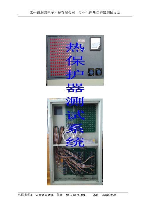
常州市润邦电子科技有限公司 专业生产热保护器测试设备
目录
一、 概述 i. 组成部分………………………………………………….…3 ii. 技术特点………………………………………………….…3
二、 硬件系统…………………………………………………………4 三、 软件系统…………………………………………………………9 四、 操作流程………………………………………………………. 21 五、 质量保证………………………………………………………..24 六、 联系方式………………………………………………………..24
电话(微信): 013915838598 传真: 0519-83751601 QQ: 228154900
常州市润邦电子科技有限公司 专业生产热保护器测试设备
三、 软件系统
1. 软件的安装
打开软件所在目录,看到如图一所示的窗口,用鼠标双击
,
进入安装程序。安装过程中全部选择
入”013915838598”,如图 2。
电话(微信): 013915838598 传真: 0519-83751601 QQ: 228154900
常州市润邦电子科技有限公司 专业生产热保护器测试设备 F ). 烘箱
烘箱根据空气流体原理进行设计,侧面加热,下面鼓风,采用 双电机,内腔的热保护器工作面的四角误差不大于±1℃。加热功率 2000W,全速加热升温速度为 10—15 度/分钟。
。在序列号内输
安装成功后,在桌面上会出现如 可以运行软件了。
所示的快捷方式,双击此图表就
安装程序
图一
电话(微信): 013915838598 传真: 0519-83751601 QQ: 228154900
常州市润邦电子科技有限公司 专业生产热保护器测试设备
- 1、下载文档前请自行甄别文档内容的完整性,平台不提供额外的编辑、内容补充、找答案等附加服务。
- 2、"仅部分预览"的文档,不可在线预览部分如存在完整性等问题,可反馈申请退款(可完整预览的文档不适用该条件!)。
- 3、如文档侵犯您的权益,请联系客服反馈,我们会尽快为您处理(人工客服工作时间:9:00-18:30)。
是在自动测试结束后有效,操作员可以进入拔板窗口。
图四
温度曲线: 以曲线的方式显示实时温度,直观地发现温度误差的大小。
电话(微信): 013915838598 传真: 0519-83751601 QQ: 228154900
常州市润邦电子科技有限公司 专业生产热保护器测试设备 测试参数的建立和修改: 设置自动测试时保护器的参数值,如图五所示。参数保存后可以立即进行自 动测试。四个烘箱可以设置不同的参数,也就是说,4 个烘箱可以同时测试 不同的产品。
电话(微信): 013915838598 传真: 0519-83751601 QQ: 228154900
常州市润邦电子科技有限公司 专业生产热保护器测试设备 e) PCB 板接线
1 PT100 传感器:从左到右,依次编号为 4,3,2,1。G 表示公共端, R 表示独立端。
2 加热模块: SSR+接模块的正极,SSR+接模块的负极。 3 485 接口: AB 分别接 RS232-RS485 转换器的 AB 端。 4 自动开关门: 同时提供一对常开常闭继电器接口。 5 电源: 为了系统可靠,提供完全隔离的 5V,12V 电源。
常州市润邦电子科技有限公司 专业生产热保护器测试设备 从最小值开始
d) 控制箱温度表菜单设置
编号 SV 窗口 PV 窗口 PV 默认值
1 PAS
0135
0000
2 Nr
0001--0099 0001
3 AJL
-99.9 ~ 99.9 各表不一样
4 AJH
-99.9 ~ 99.9 各表不一样
5 AH
常州市润邦电子科技有限公司 专业生产热保护器测试设备
温度传感器接口
加热模块接口
自动开关门接口
电源接口
控制板反面
485 通信接口
128 路温度保护器接口
c) 控制箱面板说明 ① PV 显示器(红)
显示测量温度或根据仪表状态显示参数值 ② SV 显示器(绿)
显示设定温度或仪表状态提示符 ③ 指示灯
AT 自整定指示灯(绿),开始自整定时闪烁 OUT 加热指示灯(绿),工作时亮 AL 报警灯(红),温度超出测量范围,或者高于告警温度(AH)时亮,蜂鸣器响。 TEST 系统进入自动测试状态时,此灯闪烁。 ④按键
常州市润邦电子科技有限公司 专业生产热保护器测试设备
目录
一、 概述 i. 组成部分………………………………………………….…3 ii. 技术特点………………………………………………….…3
二、 硬件系统…………………………………………………………4 三、 软件系统…………………………………………………………9 四、 操作流程………………………………………………………. 21 五、 质量保证………………………………………………………..24 六、 联系方式………………………………………………………..24
如果低规格动作温度的正负偏差都设置为 0,则在生产时跳过此规格,拔 板时也不判断此规格。
电话(微信): 013915838598 传真: 0519-83751601 QQ: 228154900
常州市润邦电子科技有限公司 专业生产热保护器测试设备
测试参数的选择:
修改或者增加测试参数
每次停止测试后: 烘箱门保持开还是关
。在序列号内输
安装成功后,在桌面上会出现如 可以运行软件了。
所示的快捷方式,双击此图表就
安装程序
图一
电话(微信): 013915838598 传真: 0519-83751601 QQ: 228154900
常州市润邦电子科技有限公司 专业生产热保护器测试设备
软件序列号
图二
电话(微信): 013915838598 传真: 0519-83751601 QQ: 228154900
共有 3 个按键 设置键。按此键进入设置菜单,可以查看参数,也可以修改参数 移位键。按此键选择需要修改的数字,被选中的会不断闪烁 增量键。按此键对选中的数字加一,如果此数字已经到了最大值,就再
电话(微信): 013915838598 传真: 0519-83751601 QQ: 228154900
电话(微信): 013915838598 传真: 0519-83751601 QQ: 228154900
常州市润邦电子科技有限公司 专业生产热保护器测试设备
三、 软件系统
1. 软件的安装
打开软件所在目录,看到如图一所示的窗口,用鼠标双击
,
进入安装程序。安装过程中全部选择
入”013915838598”,如图 2。
常州市润邦电子科技有限公司 专业生产热保护器测试设备
ii.
软件的使用
软件运行后界面如图三:
4 路温度显示区
PID 温 度 , 是实 际 记录的测试温度
温度保护器类型 自动测试/中止切换 生产信息提示区
选择闪动测试的 时间间隔
拔板按钮,自动 测试结束后有效
保护器状态显示
图三 一台计算机最多可以控制 4 台烘箱,在程序界面上分在 4 个部分。每个烘箱
0~200
200
6 Sv
0~200
0000
7P
1~200
6
8I
0~999
50
9D
0~999
6
10 T
1-60
1
11 ECD
0-10
5
12 AT
0246
0000
说明 进入设置必须输入密码”135” 控制箱的编号
温度表 0 度修正值 温度表 200 度修正值 仪表告警温度, 此温度表无效 目标温度 PID 控制的 P 值 PID 控制的 I 值 PID 控制的 D 值 PID 控制的 时间周期 PID 控制的 过冲抑制比 如果要进入 PID 整定,必须要输入此密码
电话(微信): 013915838598 传真: 0519-83751601 QQ: 228154900
常州市润邦电子科技有限公司 专业生产热保护器测试设备
目标温度显示
PID 温度显示
保护器显示区
控制板正面
电话(微信): 013915838598 传真: 0519-83751601 QQ: 228154900
闪动测试时间间隔可以选择
10ms,20ms,30ms,40ms,50ms 或不测; 保护器状态显示和控制箱上的一致,保护器闭合的时候亮(红色),打开的时 候暗(灰色); 自动测试按钮按下后,软件会显示本次测试的保护器参数,如图四.选择“确 定”后,如果烘箱控制器做出了正确响应,系统就进入自动测试状态,此时按 钮上的文字改为” 终止自动测试”,允许用户在特殊情况下强行终止测试。
电话(微信): 013915838598 传真: 0519-83751601 QQ: 228154900
常州市润邦电子科技有限公司 专业生产热保护器测试设备
二、 硬件系统 a) 组成框图
计算机系统及软件
控制箱
RS232-RS485 转换器
控制箱
控制箱
控制箱
烘箱及温度保 护器接口板
烘箱及温度保 护器接口板
有 4 个控制页面
。
生产测试:
电话(微信): 013915838598 传真: 0519-83751601 QQ: 228154900
常州市润邦电子科技有限公司 专业生产热保护器测试设备
实时显示 4 路温度
,显示 PID 温度
(此
温度是 4 路温度的平均值,也是测试过程中实际记录的温度);
温度保护器的类型可以选择常开或常闭;来自烘箱及温度保 护器接口板
烘箱及温度保 护器接口板
b) 控制板 采用高容量,高速度单周期的 CPU,其运行速度为 16M,是普通同频率 51 单 片机的 12 倍,轻松完成温度采集和开关量测试。 温度采集使用 4 路独立的 16bits Sigma-Delta A/D,每秒采集 2 次,抗干扰能力 强。采样电阻是台湾产的金属膜电阻,温飘低,线性好,整机修正误差小。 RS485 采用了防雷和防净电处理,通信更加稳定可靠,维修率大大下降。 温度采集和开关量测试使用独立电源,更加稳定可靠。
高压型,用于测量动闪和复闪。
同时测量 96 个双路 KSD,各种异形规格 本公司首创
的 KSD
市场无同类产品
专门用于测量产品的复位不同步,近
100%检出合格品温度范围内的不同步 品,速度是传统反复开关门测复闪的 2 倍以上。
专门用于测量内含 PTC 的热保护器, 也可用于常规型
测量三相热保护器
电话(微信): 013915838598 传真: 0519-83751601 QQ: 228154900
电话(微信): 013915838598 传真: 0519-83751601 QQ: 228154900
常州市润邦电子科技有限公司 专业生产热保护器测试设备
一、 概述 a) 组成部分 系统由计算机,RS232-485 中转器,控制箱和烘箱等几部分组成。 1. 计算机用于运行集控软件,采集、保存各个烘箱的温度和各个温度保 护器的开关状态。配置温度保护器的生产参数。 2. RS232-485 中转器用于联系计算机和控制箱,保证一台计算机可以控 制多台烘箱。 3. 控制箱直接测量烘箱的温度,采集温度保护器的开关状态。 b) 技术特点 1. 采用高速大容量的 CPU,将温度表和开关量采集模块集成于一块 PCB 上,系统非常精简。 2. 温度仪表采用进口元件国内组装的 A 级 PT100,具有良好的线性。温 度采集电路采用台湾产的精密金属膜电阻,温度系数为 50PPM(0.005%),线 性为 0.5%。 0 度和 200 度的未修正时的平均误差不大于 2℃,修正以后可以达到 0.2%FS 的仪表要求。 3. 四路温度采样全部采用独立的 Sigma-Delta 16 位 A/D,每秒钟采集二次。 4. 温度误差的修正不需要借助第三方的温度表,可以独立进行恒温修正, 也就是说,烘箱上不需要第三方的恒温仪表,可以节约费用。计算机软件系 统已经集成了修正程序。 5. RS485 进行防雷,防静电处理,系统运行更可靠。