SCMOS Layout Rules - Well
PADS Layout 的基本设置
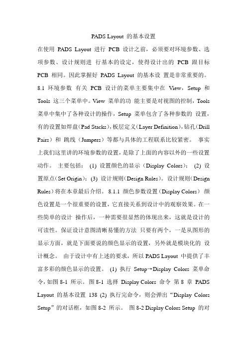
PADS Layout 的基本设置在使用PADS Layout 进行PCB 设计之前,必须要对环境参数、选项参数、设计规则进行基本的设定,使得设计出的PCB 跟目标PCB 相同。
因此掌握好PADS Layout 的基本设置是非常重要的。
8.1 环境参数有关PCB 设计的菜单主要集中在View,Setup 和Tools 这三个菜单中。
View 菜单的功能主要是对视图的控制,Tools 菜单中集中了各种设计的操作,Setup 菜单包含了各种参数的设置,有的设置如焊盘(Pad Stacks),板层定义(Layer Definition),钻孔(Drill Pairs)和跳线(Jumpers)等都与具体的工程联系比较紧密。
事实上我们这里讲的环境参数的设置,是除了上面的内容以外的一些设置动作。
主要包括:(1) 设置颜色的显示(Display Colors);(2) 设置原点(Set Origin);(3) 设计规则(Design Rules)。
设计规则(Design Rules)将在本章最后介绍。
8.1.1 颜色参数设置(Display Colors)颜色设置是一个很重要的设置,它直接关系到设计中的观察效果。
在一些简单的设计操作后,一种需要很显然的体现出来,这就是设计的可读性。
保证设计意图清晰易懂的方法只要有两个,一是从图形的显示方面,就是下面要说的颜色显示的设置,另外就是模块化的设计概念。
由于设计中有上述的要求,所以PADS Layout 中提供了丰富多彩的颜色显示的设置。
(1) 执行Setup→Display Colors 菜单命令,如图8-1 所示。
图8-1 选择Display Colors 命令第8 章PADS Layout 的基本设置138 (2) 执行完命令,则会弹出“Display Colors Setup”的对话框,如图8-2 所示。
图8-2 Display Colors Setup 的对话框一、候选颜色(Selected Color)Display Colors Setup 对话框最上面的32 个小按钮,显示了32 种颜色,只是计算机中最典型的颜色。
PCB Layout经验总结-自编

PCB Layout 参数1.Routing的最小线宽=最小间距(这是一般应该遵循的规则),对于有BGA的板子(布线密度一般较高),单端线线宽一般有:控制线表层0.25mm和内层0.1mm,对应阻抗50欧姆。
PS1:对于这样表层有焊盘间距0.65mm、焊盘直径0.35mm的BGA封装器件层走线时,未出器件焊盘区域时width取0.1mm(clearence为0.1mm),出了焊盘区域可将线宽放宽为0.25mm(clearence 0.15mm)。
PS2:较宽松的电路的最佳推荐线宽、间距一般为0.254mm(10mil)。
PS3:市场上批量生产时允许的最小线宽为表层0.12mm,内层为0.1mm。
PS4:Routing时,应该做到层内布线均匀,各布线层密度相近,这样可以对防止板子翘曲起到积极作用。
另外可以通过整层敷铜来达到相同的效果!2.普通印制板Via尺寸一般就打这几种(单位默认mm):控制线Via:(8mil,16mil)、(0.2,0.44)、(0.25,0.5)、(10mil、18.5mil)。
电源、地线Via:(0.6,1.0)。
PS1:;PS2:Via金属盘的极限制程能力虽然已经可达环宽0.1mm,但只建议用在迫不得已的情况下使用(参考PS3),推荐Via环宽最小值0.12mm,;PS3:兴森快捷给胡晓芳Layout的PCB上SN74LVC16T245附近如下,很多反常规的可取设计,比如虽然Datasheet里推荐使用0.33mm的焊盘,但板子上实际使用的是0.3mm的焊盘,图中BGA内部使用的Via尺寸全是(16mil,8mil)即(0.406m,0.203mm)。
PS4:通孔类Pad的环宽最小0.15mm,国盾要求大于0.225mm。
3.制程能力中的孔间距一博的《高速先生》第13期第24页的那篇文章中说了这一问题,此孔间距是指钻孔内壁间距,一博的制程能力是10mil。
拿常规画的PCB来说,使用(8mil,16mil)的Via,Rules设置最小Clearence:4mil,则孔内壁间距=4+2*环宽=12mil,所以直接按照Rules来走线放置Via即可。
CMOS设置详解一
CMOS设置详解⼀开机后,当屏幕出现⾃检信息时,屏幕下⽅会出现⼀⾏“Press Del to ENTER Setup",这时按下Del键可以进⼊CMOS设置程序。
⾸先了解菜单项的中⽂含义STANDARD CMOS SETUP标准CMOS设置BIOSFEATURESSETUPBIOS标准设置CHIPSETFEATURESETUP芯⽚组设置POWERMANAGEMENTSETUP 电源管理设置PNP/PCICONFIGURATION 即插即⽤设备与外围设备设置LOAD BIOS DEFAULTS 载⼊BIOS缺省值SUPERVISORPASSWORD 更改管理员密码USERPASSWORD 更改⽤户密码IDEHDDAUTODETECTION⾃动检测IDE设置SAVEEXITSETUP 存盘退出EXITWITHOUTSAVE不存盘退出CMOS设置中各项含义1,DATE(⽇期)2,TIME(时间)3,HARDDISKS(硬盘)AUTO:允许系统开机时⾃动侦测硬盘类型NONE:没有安装USER:⾃⾏设置参数,HEAD(磁头数),PRECOMP(写⼊补偿),可根据硬盘说明书添写4,设置软件驱动器设置A盘与B盘的软驱型号。
没有为NONE。
5,设置显⽰设备现有主板的显卡类型⼏乎全是彩⾊显卡(EGA/VGA),所以您只要让该项保持默认即可。
6,系统除错整体模式⼀般⽤“ALL ERROR”。
BIOS FEATURES SETUP(BIOS基本设置)英⽂翻译设置值1,VIRUSWARNING病毒防护警告 DISABLED2,CPUINTERNALCACHECPU⼀级缓存ENALBED3,EXTERALCACHECPU⼆级缓存ENALBED4,OPEN POWER ON SELF TEXT 开机快速⾃检 ENABLED(可不检测)5,BOOT SEQUENCE 开机磁盘引导顺序 "C,A,CDROM"6,SWAP FLOPPY DRIVE 软盘驱动器互换可根据实际情况选择A或B7,BOOT UP FLOPPY SEEK 开机软盘搜索可根据实际情况选择8,SECURITY 安全选项进⼊系统密码SYSTEM进⼊CMOS密码SETUP9,PIC/VGA PALETTER SNOPP 彩⾊显卡调⾊板调整 ENABLED10,VIDEO BIOS SHADOW 视频BIOS缓冲 ENABLED11,CE000-CBFFF SHADOW 区域映射⽅式 ENABLED即插即⽤与PCI设置状态1,PNP INSTALLED YES2,RESOURCES CONTROLLED AUTO3,RESET CONFIGATION DATA ENABLED载⼊BIOS缺省值,必须要⽤YESIDE HDD AUTO DETECTION(⾃动检测IDE硬盘)设置已装硬盘类型为"AUTO"的话,系统在每次开机时⾃动检测硬盘的类型,就不必再进⼊CMOS中检测了。
莫蒂克-S1系列-sCMOS显微镜相机-使用手册说明书
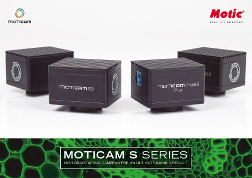
MOTICAM S SERIES HIGH GRADE sCMOS CAMERAS FOR AN ULTIMATE IMAGING RESULTMotics new sCMOS cameras, designed by German engineers a nd ma nufa ctured by professiona ls represent a n impressive impetus to microscope camera performance. With a member of this pro-duct line the door for new application fields opens wide. The a ccelera ted da ta rea dout ena bles to work on fast phenomena in biology and industry.FPSFAST FRAME RATESS CMOS sCMOS SENSORSNEW MOTICAM S SERIESOur well-known Motic Ima ges softwa re, a lwa ys with a cost-free upgrade option is included in all camera packages and enables to view images at ma ximum qua lity, ca pture, edit, mea sure a nd report the result... all these features are ready to work on your PC or laptop.USB 3.1USB 3.1 INTERFACEMIP 3.0 SOFTWAREMAXIMUM DETAILSIf it is about maximum resolution for display or printing, Moticam S12 is your choice. A 25 fps* fra me ra te ma na ges the la rgest da ta volume of a ll Motica m S models. If thetiniest detail is in your focus, Moticam S12 is your solution.LOW LIGHT , FAST PHENOMENAMoticam Pro S5 Lite delivers a 5MP mid-size resolution for all biological/medical fields, showing a premium sensitivity for lowlight situa tions in Fluorescence a nd Pola riza tion. The Global shutter data readout helps to accelerate data transfer from fast phenomena, from single-cell organisms to industrial work with clockworks or extrusion processes.AN UL TIMATE SOLUTION, STILL AFFORDABLEMoticam Pro S5 Plus carries a large 2/3” sensor with 5MP resolution at a maximized frame rate of 70 fps* in full resolution. This camera covers all important aspects of imaging: resolution for detail information, speed for fast phenomena and a large sensor to coverextended areas in a single shot.1/1.7"USB 3.112.0 MP2/3"USB 3.15.0 MP2/3"USB 3.15.0 MP*Frames per second under optimal lighting conditions and in compliance with computer technical requirements.MOTIC IMAGES PLUS 3.0 SOFTWARE*Frames per second under optimal lighting conditions and in compliance with computer technical requirements.***********************************1-877-977-4717 (604) 。
学CMOS设置技巧123

不要老是抱怨显卡不好,说不定是你没将AGP 4X模式打开哦!建议你到“Advanced Chipset Features(高级芯片组设置)”当中检查一下“AGP Device 4X Support(AGP 4X模式)”是不是已设置为“Enabled”,表示设置AGP显卡是AGP 4X运行;如果你所使用的AGP显卡不支持AGP 4X,务必要设定为“Disabled”。另外,还可以将“AGP Graphics Aperture Size”设置AGP显卡的显示内存大小,一般设为“64MB”。
目前市面的主板厂商多达数百家,不同的主板所采用的BIOS也有不同类型(主要有Award BIOS和AMI BIOS)和不同版本(Award BIOS主要有V6.00版、V4.60版和V4.51版)的区别,如何才能对所有的设定有一个全盘的了解呢?虽然有那么多的主板,其实设置都是大同小意的,只不过某些设置项目会有些增减或者也仅仅是改变一个名称而已。本文就以美达S845G主板所使用的Award BIOS V6.00PG为例,教大家全面打探“蓝色禁区”。
一、检测篇
1.自动检测硬盘、光驱型号
一般来说,装完机后要设置硬盘的参数,以便顺利开机。在主菜单中选择“Standard CMOS Features(标准CMOS功能设置)”,然后再分别选择“IDE Primary Master(第一个IDE主控制器)”、“IDE Primary Slave(第一个IDE从控制器)”、“IDE Secondary Master(第二个IDE主控制器)”、“IDE Secondary Slave(第一个IDE从控制器)”。在以上四个项目按下回车键后会出现一个子菜单,然后在“IDE HDD Auto-Detection”项目,按下回车键后,会自动检测IDE设备,如图2所示。如果检测到IDE硬盘设备,会在此界面中列出的容量等信息,并在“Standard CMOS Features”中显示该IDE硬盘的型号信息。如果是其它IDE设备,只在“Standard CMOS Features”中显示该IDE设备的型号信息。
CMOS工艺和器件完整版

poly n+ p-well n+
poly p+ n-well p+
CMOS工艺(双阱)环节示意 CMOS Process steps (4)
Start adding metal layers(matal1, metal2…)
metal 1
active
active掩膜版:为薄氧化层区掩膜,用以拟定薄氧化层区旳面积 和位置。该区域覆盖了全部PMOS和NMOS管旳源、漏和栅旳制 作区域,故该版又称为有源区版(active版)
制造环节:用该版完毕薄氧化层(栅氧化层)旳生长
CMOS工艺(N阱)详细制造环节(2)
mask剖面图
p-substrate
+
a
out inputs
VDD
pullup network
out pulldown network
VSS
CMOS
怎样制造CMOS?
双阱制造工艺
单阱(N阱)制造工艺
CMOS工艺与器件
CMOS旳概念 CMOS制造工艺 MOS管旳电性能 连线 CMOS器件旳版图设计
CMOS工艺(双阱)环节示意 CMOS Process steps (1)
n-well
active mask(负胶) mask俯视图 active
制造环节:用active掩膜版(负胶),完毕场氧层生长
CMOS工艺(N阱)详细制造环节(3)
mask剖面图
poly mask
p-substrate
n-well
mask俯视图
polysilicon
poly掩膜版:多晶图形掩膜,用于制作多晶硅栅极以及形成电路构造 旳多晶硅连线和电阻
莫蒂克 sCMOS 摄像头说明书

USB CAMERASThe new Motic sCMOS cameras developedby German engineering represent a newimpetus to manufacturing quality, technicalprecision and l ightweight design. With amember of this line the door for new appli-cation fiel ds opens wide. The accel erateddata readout (Rolling Shutter) also enablesto work on fast moving phenomena.The Moticam S3 delivers a mid-size resolu-tion of 3MP, a owing a ba ance betweenspeed and resolution. For teaching purpos-es and routine l abs, diverse tasks frombiology, medicine and industry are covered.The back l ight techno l ogy of the sCMOSsensor guarantees state of the art imagingfor professional image results.USB3.13.0 MPTECHNICAL SPECIFICATIONS MOTIC IMAGES PLUS 3.0 IMAGE ANALISYS SOFTWARE Motic Images Plus 3.0By connecting your Moticam to your computer you will beable to work with our well-known softwared that comesincluded in the package. View, capture, edit, measure,make reports... al its standard features and the newones packed in a new user-friendly interface.*Frames per second under optimal lighting conditions and in compliance with computer technical requirements.Sensor typeSensor sizeImaging areaCapture resolutionLive display mode through USBPixel sizeScan modeShutter modeData transferMax. frames per second (fps*)Exposure timeOperating temperatureSensitivitySupport deviceSupported OSMinimum computer requirementsLens mountSoftwareFunctions Power supplyPackage includes sCMOS 1/2.8"6.44mm (Diagonal)3MP 2048x1536, 1920x1080 pixels 2.5x2.5µm Progressive Rolling Shutter USB 3.12048x1536 @ 60fps 1920x1080 @ 60fps 21 µsec to 2 sec From -10 to +60 Degrees Celsius non condensing 600mV(G) @ 1/30 sec TWAIN, SDK and DirectShow Driver Microsoft Windows 7/8/10, MAC OSX10.9, Linux or higher 2GHz dualcore - RAM memory 2GB - Video memory min. 512 MB C-Mount Motic Images Plus 3.0 for Windows, OSX and Linux Still image and video capture, live and still image measurement, imageadjustments, white balance, automatic & manual exposure, individualobjective calibration system.5V (from USB Port)CS ring adaptor, USB 3.1 cable, Motic 4-dot calibration slide, MoticImages Plus 3.0 for PC/OSX/LinuxGrab your image with highest sensor sensitivity. Navigate in the dark!。
nwell_rule CMOS设计规则

1.N 阱 (um)N 阱最小阱宽D1=4N 阱最小间距不同电位(高压与低压)D2=14N 阱最小间距同电位D2=0N 阱内N 阱边界到P +和N +扩散的最小间距D3=4N 阱外N 阱边界到P +扩散的最小间距D4=8N 阱外N 阱边界到N +扩散的最小间距D5=132.有源区扩散的最小宽度(管子的最小宽度)(无孔时)D6=4同型扩散的最小间距D7=4N 阱内N +扩散到P +扩散的最小间距D8=3N 阱外N +扩散到P +扩散的最小间距D9=53.场区注入N 场区版由N 阱版每边扩5得到 D10=4P 场区版取N 场区版的反版4.多晶硅最小多晶硅的宽度D11=3在掺杂区上多晶最小间距D12=3多晶硅盖过场区 extend D13=3场区上的多晶硅到场区的最小间距D14=1栅到场区边缘的最小距离(无引线孔)D15=3D3D6D9P+有源区N 阱N场N+D5D4D7D8D1N+D2D3N 阱D10D15D115.N 管源漏N select overlap N 管源漏包N +扩散区D16=2N 管源漏最小宽度D17=5N 管源漏最小间距 space between n-select D18=2N 管源漏到P +扩散区的最小间距D19=1P 管源漏版由N 管源漏版的反版得到6.引线孔最小接触孔宽D20=3有源区孔到有源区的最小距离D21=2铝包孔D22=2孔间最小间距D23=3孔到多晶的最小间距D24=3多晶包孔D25=2多晶的孔到扩散区间距D26=27.金属最小宽度D27=3最小间距D28=38.钝化孔钝化孔尺寸D29=1002钝化空的间距D30=100金属包钝化孔D31=5n 管源漏n+n+D18D19多晶硅铝D28D27铝D22D21D24D25D26有源区。
第二讲集成电路版图设计规则
- 1.5mA 最大电流密度
/um
-
- 禁止并行金属线90度拐角,用135
度拐角代替
a
c.2
b
c.1 c.2
设计规则 via
定义为两层金属之 间的连接孔
符号 尺寸
含义
12.a .7*.7 过孔最小面积
12.b 0.8 过孔间距
12.d~f - 接触孔、poly-poly电容和栅 上不能打过孔
12.g 0.4 金属1对过孔的最小覆盖
6.d 6.e 6.f 6.g
尺寸 1.2 1.0 0.5 3.2 1.5 0.8 -
含义 poly2做电容时的最小宽度 poly2做电容时的最小间距 Poly2与有源区的最小间距 做关键电容时的间距 电容底板对顶板的最小覆盖 电容Poly2对接触孔最小覆盖 Poly2不能在有源区上 Poly2不能跨过poly1边沿
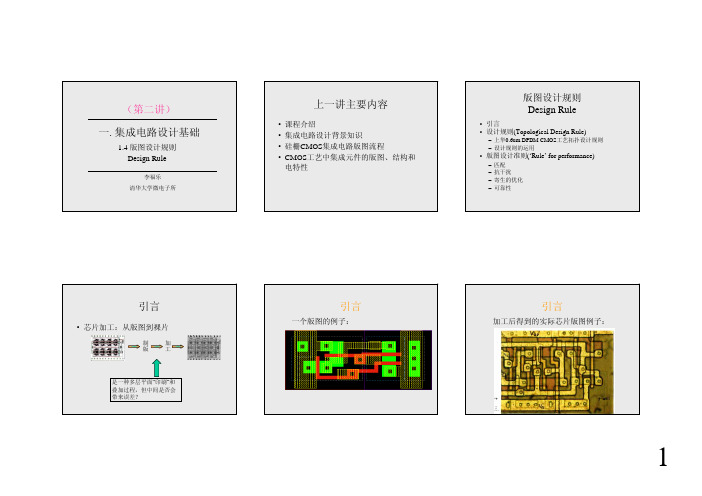
– 上华0.6um DPDM CMOS工艺拓扑设计规则 – 设计规则的运用
• 版图设计准则(‘Rule’ for performance)
– 匹配 – 抗干扰 – 寄生的优化 – 可靠性
引言
• 芯片加工:从版图到裸片
制
加
版
工
是一种多层平面“印刷”和 叠加过程,但中间是否会 带来误差?
引言
一个版图的例子:
习)
VDD
15k
OUT IN 80/0.8
又试问NMOS晶体管的漏极面积和周长是多 少?
设计规则的运用
• TASK3:设计一个简单开关电容电路 (练习)
f1 IN
30/0.6 X
f2 OUT
60/0.6 2pF 6/0.6 12/0.6
又试问X点的寄生电容如何计算?
CMOS工艺流程版图剖面
Top View
Cross-Section
79
N+ and P+ Regions
Top View
Cross-Section
Ohmic contacts
80
SiO2 Upon Device & Contact Etching
Top View
Cross-Section
81
Metal Layer – by Metal Evaporation
N-well
Legend of each layer
P-diffusion N-diffusion
Polysilicon
Metal
contact
75
Process
field oxide
field oxide
field oxide
76
3. Simplified CMOS Process Flow
Create n-well and active regions
P+
掩膜版
光刻4,刻P+离子注入掩膜版
N阱
15
N+离子注入
N+
光刻5,刻N+离子注入掩膜版
N阱
16
生长磷硅玻璃PSG
PSG
N阱
17
光刻接触孔
光刻6,刻接触孔掩膜版
N+
P+
N阱
18
刻铝
光刻7,刻Al掩膜版
Al
N阱
19
刻铝
VSS
Vo
VDD
N阱
20
钝化层
光刻8,刻压焊孔掩膜版
N阱
21
2) 清华工艺录像
电脑CMOS设置详细操作方法

电脑CMOS设置操作方法BIOS和CMOSBIOS的概念想必大家已经清楚了,但什么是CMOS呢?平时谈到BIOS设置时经常说成是CMOS设置,将二者混谈,这似乎并没有引起多大的误会。
从物理特性来讲,CMOS是一种特殊的存贮器(CMOS RAM),在主机关机后它由主板上的电池来提供维持存贮数据所需的电压。
BIOS 使用CMOS来存贮用户更改的设置参数。
微机中的日期和时间设置也是存贮在CMOS中的。
开机时,BIOS首先是调用CMOS中设置的参数来配置微机系统。
一旦CMOS数据失效(主要是电池失效或放电引起),BIOS会调用本身缺省的设置参数来启动微机。
所以我们说“BIOS设置”或“CMOS设置”都不算错。
不同的电脑可能有不同界面,但常见的也就是AWARD、AMI、Phoenix等几种。
界面形式虽然不同,但功能基本一样,所要设置的项目也差不多。
这是AWARD的CMOS设置画面,是最常见的一种。
其实你只要明白了一种CMOS的设置方法,其它的就可以触类旁通了。
在主界面的下面有很多个参数需要设置,大部分项目本来就已经设置了正确的参数值,或者说许多选项对电脑的运行影响不太大,所以一般我们只要注意几个关键项就可以了。
通常,我在设置CMOS时,只简单地做以下几步:1、设置出厂设定值2、检测硬盘参数3、设置软驱4、设置启动顺序5、如果有必要可以设置密码介绍Award BIOS Setup的常用选项的含义及设置办法。
更改设置后,选Save and Exit Setup项或按F10键保存,使所修改的内容生效。
AWARD BIOS是一种比较常用的BIOS,各主板制造商都其基础根据主板特性上进行了调整。
因而本文只介绍了AWARD BIOS的一些最普遍的设置,以供参考,读者还应仔细阅读随主板附带的说明书。
AMI BIOSBIOS是英文Basic Input/Output System(基本输入/输出系统)的缩写,其程序储存在主板上的 EPROM或Flash ROM 内,作用是测试装在主板上的部件能否正常工作,并提供驱动程序接口,设定系统相关配备的组态。
版图设计规则

设计规则(design rule)
版图几何设计规则可看作是对光刻掩模 版制备要求。光刻掩模版是用来制造集 成电路的。这些规则在生产阶段中为电 路设计师和工艺工程师提供了一种必要 的信息联系。
• 版图的设计有特定的规则,规则是集成 电路制造厂家根据自已的工艺特点而制定 的。因此,不同的工艺就有不同的设计规 则。设计者只有得到了厂家提供的规则以 后,才能开始设计。
第七页,编辑于星期三:二十点 分。
设计规则(design rule)
两种规则: (a) 以λ(lamda)为单位的设计规则—相对单位 (b) 以μm(micron)为单位的设计规则—绝对单位 如果一种工艺的特征尺寸为S μm,则λ=S/2 μm, 选用λ为单位的设计规则主要与MOS工艺的成比例缩 小有关。
第二十页,编辑于星期三:二十点 分。
Layer Processing(层处理命令)
•层处理命令的类型
第二十一页,编辑于星期三:二十点 分。
Layer Processing(层处理命令)
•Logical Commands(逻辑命令)
ndiff poly Original layer
第二十二页,编辑于星期三:二十点 分。
第九页,编辑于星期三:二十点 分。
设计规则(design rule)
•TSMC_0.35μm CMOS工艺中各版图层的线条最小宽度
第十页,编辑于星期三:二十点 分。
设计规则(design rule)
2、最小间距(minSep) 间距指各几何图形外边界之间的距离。
第十一页,编辑于星期三:二十点 分。
;多晶硅
W1 = geomOr( "W1" )
版图设计讲稿

R=R□well•L/W
* 典型值: R□well=0.85k
N+ P型衬底 N阱 N+
场氧
集成电阻
N+
场氧 N阱 N+ Cj 耗尽区 VDD Cj/2 R Cj/2 Vout
S
B
G
L
NMOS晶体管版图
S NMOS晶体管符号
D G S
FOX N+ N+
B
P+
N管 源漏区
NMOS晶体管剖面图
MOS晶体管
• PMOS晶体管的 版图和结构
D B PMOS晶体管版图 S PMOS晶体管符号
B
S G D
W L
G
B
N+
S G D
FOX
P+
P+
N-阱 N-阱
P-substrate P管 源漏区
金属3
金属2 金属1 多晶硅
(50~60%C)
衬底双极晶体管(BJT)
• 衬底BJT * 有源元件之一 * 对于N阱CMOS工艺,可实现PNP BJT * 可用于电压基准电路
衬底BJT
• PNP BJT的版图和结构
P型衬底 特点:
E B C N阱
1)集电极C电压受到限制, 须接地
2)基区宽度WB没有很好 控制,电流增益差别较大 3)结构上的两个主要参数: 基区宽度WB和BE结面积A C P+ WB P型衬底 E P+ B
* 单位面积电容最大的电容 * 沟道电阻问题
P型衬底
集成电容
• MOS电容:
* 非线性电容 适用于电源滤波 Cch
LAYOUT详解1
LAYOUT OF RESISTORS
Integrated resistors are made of thin strips of resistive layer ❒ a resistive strip is contacted at the two terminals by ohmic contacts (metal – p+ or n+) ❒ insulation from the surrounding is made by oxide layers or by reversely biased junctions
Source
Drain
Gate
Active Area Poly
Metal Contact
IC Technology & Layout
TRANSISTOR MATCHING
Orientation Boundary conditions
Different undercut
Current flow direction
n
n
p
n– 50 nm
n
p-well
p
– additional implant to adjust threshold voltages
polysilicon
n p p
n–
p-well
– definition of polysilicon gates and capacitor bottom plates
Metal Contact Poly gate Active area
n-Well n+ Diffusion Well bias p+ Diffusion Substrate bias
电脑主板layout规范

电脑主板layout规范一:机构尺寸:①A TX:305?CM(12000mil×?) ※“?”可调整尺寸。
②MIC-A TX:245×?CM(9600MIL×?③PCB四角应有50mil斜角。
定位孔:①定位孔圆心距板边(5,5)mm,(200,200)mil.②定位孔尺寸4mm(157mil),孔为NPTH.③一片板子最少需有三个(含)以上定位孔.光学点:①光学点圆心距离板边(5,10)mm,(200,400)mil.最小不得小于5mm.②光学点直径1mm(40mil),使用圆形。
③光学点防焊层直径3mm.(layer28、layer29 copper)④一片板子最少需有三个(含)以上光学点。
⑤若背面有放SMD零件,也须放光学点。
螺丝孔:①目前板子有A TX和MIC-A TX二种,螺丝孔位置有些许不同。
②螺丝孔正中间的孔为NPTH,不接任何NET。
③螺丝孔外圈8个P AD NET须接到此区域GND。
固定零件:须依坐标放在固定位置,不可任意更动:KB、USB(LAN)、COM、PRN、VGA、Sound、Game port AGP、PCI、CNR、AMP二:Placement顺序: 1.机构零件先摆。
(须用坐标去摆,全部过程中要用键盘,不可用鼠标)2.大零件先摆定:CPU、北桥、南桥、PWM、DIMM、CLK、A TK、A TX-CON、IDE、FDC、Sound\、Super l/O、BIOS3.须看线路图一页一页依据大零件摆零件,不可摆在不相关位置或摆的很远。
在摆同时须依照走线将方向确定,不是摆了就可以。
(有时线路图画在这一页,但不见得就摆在这里,须注意NET的接法)注意事项:1.放置零件时格点需设定为G25,零件原点固定朝左或朝上。
2.零件不可排的过近(外框不可有重迭现象),尤其同是DIP零件如:EC对EC、EC对CHOKE…会使生产加工零件产生挤推,造成零件浮件状况。
- 1、下载文档前请自行甄别文档内容的完整性,平台不提供额外的编辑、内容补充、找答案等附加服务。
- 2、"仅部分预览"的文档,不可在线预览部分如存在完整性等问题,可反馈申请退款(可完整预览的文档不适用该条件!)。
- 3、如文档侵犯您的权益,请联系客服反馈,我们会尽快为您处理(人工客服工作时间:9:00-18:30)。
SUBMRule DescriptionLambda Microns 1.1 Minimum width 12 3.6 1.2 Minimum spacing between wells at different potential 18 5.4 1.3 Minimum spacing between wells at same potential 6 1.8 1.4 Minimum spacing between wells of different type (if both are drawn) 0 0Note: For analog and critical digital designs, MOSIS recommends the minimum MOS channel widths (active under poly) to be 10 lambda i.e.3 microns for submission to AMI ABN (1.5 micron process) and C5N (0.5 micron process).SCMOS Layout Rules - PolySUBMRule DescriptionLambda Microns 3.1 Minimum width 2 0.6 3.2 Minimum spacing over field 3 0.9 3.3 Minimum gate extension of active 2 0.6 3.4 Minimum active extension of poly 3 0.9 3.5 Minimum field poly to active 1 0.3SCMOS Layout Rules - SelectSUBM Rule DescriptionSUBM Microns4.1 Minimum select spacing to channel of transistor to ensure adequatesource/drain width3 0.94.2 Minimum select overlap of active 2 0.6 4.3 Minimum select overlap of contact 1 0.34.4 Minimum select width and spacing(Note: P-select and N-select may be coincident, but must notoverlap) (not illustrated)2 0.6SCMOS Layout Rules - Contact to PolyOn 0.50 micron process (and all finer feature size processes), it is required that all features on the insulator layers (CONTACT, VIA, VIA2) must be of the single standard size; there are no exceptions for pads (or logos, or anything else); large openings must be replaced by an array of standard sized openings. Contacts must be drawn orthogonal to the grid of the layout. Non-Manhattan contacts are not allowed.Since we want to avoid half lambda spacing rules (contact overlap in 5.2) we use the alternative rules which reduce the overlap but increase the spacing to surrounding features. Rules 5.1, 5.3, and 5.4, still apply and are unchanged.SimpleContact to PolySUBMRule DescriptionSUBM Microns5.1 Exact contactsize2x2 0.6x0.65.3 Minimumcontact spacing3 0.95.4 Minimumspacing to gateof transistor2 0.65.2.b Minimum polyoverlap1 0.35.5.b Minimumspacing to otherpoly51.55.6.b Minimumspacing toactive (onecontact)20.65.7.b Minimumspacing toactive (manycontacts)3 0.9Note: Rule 5.2 is disabled, instead 5.2b, 5.5b, 5.6b, 5.7b are enabled inaddition to rules 5.1, 5.3, 5.4SCMOS Layout Rules - Contact to ActiveSimpleContact to ActiveSUBMRule DescriptionLambda Microns 6.1 Exact contact size 2x2 0.6x0.66.3 Minimum contactspacing 3 0.96.4 Minimum spacing togate of transistor 2 0.66.2.b Minimum activeoverlap 1 0.36.5.b Minimum spacing todiffusion active 5 1.56.6.b Minimum spacing tofield poly (onecontact)2 0.66.7.b Minimum spacing tofield poly (manycontacts)3 0.96.8.b Minimum spacing topoly contact4 1.2If your design cannot handle the 1.5 lambda contact overlap in 6.2, use the alternative rules which reduce the overlap but increase the spacing to surrounding features. Rules 6.1, 6.3, and 6.4, still apply and are unchanged. Contacts must be drawn orthogonal to the grid of the layout. Non-Manhattan contacts are not allowed.Note: In order to avoid half lambda spacing rules, Rule 6.2 is disabled, instead 6.2b, 6.5b, 6.6b, 6.7b, 6.8b are enabled in addition to rules 6.1, 6.3, 6.4. Contacts must be drawn orthogonal to the grid of the layout. Non-Manhattan contacts are not allowed.SCMOS Layout Rules - Metal1SUBMRule DescriptionLambda Microns 7.1 Minimum width 3 0.9 7.2 Minimum spacing 3 0.9 7.3 Minimum overlap of any contact 1 0.3 7.4 Minimum spacing when either metal line is wider than 10 lambda 6 1.8SCMOS Layout Rules - ViaSUBMRule Description3+ Metal ProcessLambda Microns 8.1 Exact size 2 x 2 0.6x0.6 8.2 Minimum via1 spacing 3 0.9 8.3 Minimum overlap by metal1 1 0.3 8.5 Minimum spacing to poly or active edge 2 0.6Note: Rule 8.4 is not considered for the process we are using since stackedvias are allowedSCMOS Layout Rules - Metal2SUBMRule Description3+ Metal ProcessLambda Microns 9.1 Minimum width 3 0.9 9.2 Minimum spacing 3 0.9 9.3 Minimum overlap of via1 1 0.3 9.4 Minimum spacing when either metal line is wider than 10 lambda 6 1.8SCMOS Layout Rules - Poly2 for CapacitorThe poly2 layer is a second polysilicon layer (physically abovethe standard, or first, poly layer). The oxide between the twopolys is the capacitor dielectric. The capacitor area is the areaof coincident poly and electrode.SUBMRule DescriptionLambda Microns 11.1 Minimum width 7 1.2 11.2 Minimum spacing 3 0.9 11.3 Minimum poly overlap 5 1.511.4 Minimum spacing to active or well edge(not illustrated) 20.611.5 Minimum spacing to poly contact 6 1.8 11.6 Minimum spacing to unrelated metal 2 0.6SCMOS Layout Rules - Poly2 for TransistorSame poly2 layer as for capsSUBMRule DescriptionLambda Microns 12.1 Minimum width 2 0.6 12.2 Minimum spacing 3 0.9 12.3 Minimum electrode gate overlap of active 2 0.6 12.4 Minimum spacing to active 1 0.3 12.5 Minimum spacing or overlap of poly 2 0.6 12.6 Minimum spacing to poly or active contact 3 0.9SCMOS Layout Rules - Poly2 ContactSUBMRule DescriptionLambda Microns 13.1 Exact contact size 2 x 2 0.6x0.6 13.2 Minimum contact spacing 3 0.9 13.3 Minimum electrode overlap (on capacitor) 3 0.9 13.4 Minimum electrode overlap (not on capacitor) 2 0.6 13.5 Minimum spacing to poly or active 3 0.9SCMOS Layout Rules - Via2Vias must be drawn orthogonal to the grid of the layout. Non-Manhattan vias are not allowed.SUBMRule Description3 Metal ProcessLambda Microns 14.1 Exact size 2x2 0.6x0.6 14.2 Minimum spacing 3 0.9 14.3 Minimum overlap by metal2 1 0.3 14.5 Via2 may be placed over contactNote: Rule 14.4 is not considered for the process we are using since stackedvias are allowedSCMOS Layout Rules - Metal3SUBMRule Description3 Metal ProcessLambda Microns 15.1 Minimum width 5 1.5 15.2 Minimum spacing to metal3 3 0.9 15.3 Minimum overlap of via2 2 0.6 15.4 Minimum spacing when either metal line is wider than 10 lambda 6 1.8SCMOS Layout Rules - High ResSUBMRule DescriptionLambda Microns 27.1 Minimum HR width 4 1.2 27.2 Minimum HR spacing 4 1.22 0.6 27.3 Minimum spacing, HR to contact(no contacts allowed inside HR)27.4 Minimum spacing, HR to external active 2 0.6 27.5 Minimum spacing, HR to external poly2 2 0.627.6 Resistor is poly2 inside HR; poly2 ends stick out for contacts, theentire resistor must be outside well and over field27.7 Minimum poly2 width in resistor 5 1.5 27.8 Minimum spacing of poly2 resistors7 2.1(in a single HR region)27.9 Minimum HR overlap of poly2 2 0.6SCMOS Layout Rules - OverglassNote that rules in this section are in units of microns. They are not "true" designrules, but they do make good practice rules. Unfortunately, there are no really goodgeneric pad design rules since pads are process-specific.Rule Description Microns 10.1 Minimum bonding passivation opening 60 10.2 Minimum probe passivation opening 20 10.3 Pad metal overlap of passivation 6 10.4 Minimum pad spacing to unrelated metal 30 10.5 Minimum pad spacing to active, poly or poly2 15。
