C6726+Flash+Boot调试笔记
FLASH TOOLS工具使用指书
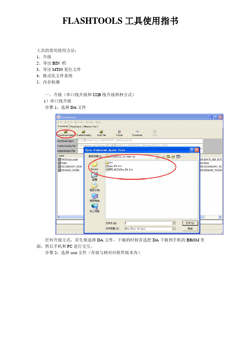
FLASHTOOLS工具使用指书工具的常用使用方法:1、升级2、导出BIN 档3、导出MT03复位文件4、格式化文件系统5、内存检测一、升级(串口线升级和USB线升级两种方式)1)串口线升级步聚1:选择DA文件任何升级方式,首先要选择DA文件,下载的时候首选把DA下载到手机的BROM里面,然后手机和PC进行交互。
步聚2:选择scat文件(存放与相对应软件版本内)Scat文件的目的:FLASH TOOL根据SCA T文件解析后定位每个load升级到FLASH 对应的起始地址及BIN档的个数。
步聚3:自动格式化文件系统目的:为了保证文件系统可以重新生成。
(因为每个软件版本文件系统分配可能不同,也就是文件的个数,默认值都不尽相同,如果不格式化,导致升级后重新开机读取相应的新文件读取失败导致异常。
)步聚4:串口线与PC端连接手机关机,连接串口线,点击工具端的DOWNLOAD或者按F9,手机按开机键进入下载模式即可。
2)USB线升级(USB分为首次下载和后续升级两种模式)后续升级可以直接使用USB升级方式,方法同串口线下载相同,简单总结A、选择DA文件B、选择scat文件C 、选择USB下载模式D、选择自动格式化文件系统然后与PC端连接即可复习:25平台07B对应机型(K119、K201、K27、i266、i289C、i530)与29平台对应机(i6、i18)使用USB线升级按*键才能进入下载模式25平台06B对应机型(i388、i389、i628、i268等) 与28平台对应机型(i269、i188、i399、i8)使用032的串口线升级按开机键才能进入下载模式35平台V0和V1的机型都是采用夹具升级(夹具所使用的是032串口线)二、导出BIN档(连接方式同升级)导BIN档的目的:在软件开发、测试过程中经常出现一些偶尔才能试到的问题,并且一旦出现就不会恢复或极易重现。
但如果重新下载软件、恢复出厂设置等类似文件系统的操作却会导致故障消失,给软件分析解决带来不便。
C6000(6713示例)的Flash烧写

C6000(6713示例)的Flash烧写1、安装Flashburn 2.71,启动CCS,Load Gel Files,具体操作如下图1所示。
2、打开Tools-flashburn,Files-New,具体操作如下图2所示。
3、Conversion输入转换CMD,Files To Burn输入待烧写文件,Fbtc Program File输入FBTC.out (根据不同的FLASH进行修改控制字以及ROM位宽)连接文件。
Flash Physical输入起始地址,Byte输入长度4、保存设置,Program-Download FBTC,连接目标板。
5、Program-Erase查出已有的程序,Program-Program Flash进行烧写,具体操作如下图3、图4所示。
附录:DEC-6713/DM642boot程序的编写。
DEC6713codec程序:1.添加DEC6713_boot的GEL文件,打开CODEC_IIS的工程文件.2.往CODEC_IIS工程里面添加boot_c671x_2.s62, c6713_emif.s62两个文件3.用DEC6713_boot的lnk2.CMD文件替换CODEC_IIS自带的CODEC_IIS.cmd4.添加BOOT_C671x.h62到DEC6713_CODEC_IIS的include文件夹里面,右击DEC6713_CODEC_IIS.PJT,Scan All Files Depedencies5.Build ALL6.把DEC6713_CODEC_IIS.out hex6x.exe放在同一个目录,修改DEC6713_boot工程文件的boot.cmd,参考如下DEC6713_CODEC_IIS.out-a-memwidth 8-image-map DEC6713_CODEC_IIS.mapROMS{FLASH: org = 0x90000000, len = 0x0040000,romwidth = 8, files = {BOOT.hex}}SECTIONS{.boot_load /* : PADDR = 0x90000000 */.text.cinit生成BOOT.hex烧写文件,boot.hex文件名可以根据files = {BOOT.hex}来修改.5.图15.图25.图35.图4。
uboot调试指南

Uboot调试参考指南一、调试目的Uboot的调试旨在通过观察uboot运行时状态来测试硬件问题。
二、调试步骤1.修改代码在uboot代码路径下,编辑uboot代码,需要做以下修改;a.修改config.mk文件,添加以下两行内容:AFLAGS += -Wa,-gdwarf2CFLAGS += -g2 -gdwarf-2b.修改. /arch/powerpc/lib/board.c文件debug("Now running in RAM - U-Boot at: %08lx\n", dest_addr);printf("Now running in RAM - U-Boot at: %08lx\n", dest_addr);将debug改为printf,如上所示。
2.编译uboot执行make BSC9131RDB_SYSCLK100_NAND,编译uboot3.将编译好的u-boot-nand.bin(uboot image格式)及u-boot(elf格式文件)文件拷贝出来4.烧录uboot将步骤3中保存的u-boot-nand.bin烧录到目标板中,烧录过程略。
5.建立工程a.在cw界面,点击file->import, 选择code warrior -> Power architecture ELFexecutable,如图1所示:图1 建立elf工程b.选择步骤3中保存的u-boot(elf格式文件),toolchain选择bareboard application,target OS选择none,工程名字请根据需要设置,比如我的机器上设置为example,点击next,如图2所示:图2 载入elf文件c.选择处理器,9131,如图3所示图3 选择处理器d.选择调试链接使用硬件,如图4所示图4 选择调试链接使用硬件e.配置硬件连接特性,图5所示图5 配置工程连接特性f.完成工程创建6.匹配源代码Uboot调试工程创建完成后,通过在修改uboot代码编译的uboot elf文件中已经包含符号表信息,其对应的源代码信息已经包含着elf文件中,因为我们的uboot编译是在linux服务器上执行,而cw的调试是在Windows机器上,因此,需要将uboot elf中的代码信息链接到windows的代码中。
uboot 命令详解

u-boot 技术文档1.U boot 命令详解1.1查看帮助命令使用help 或者?1.2环境变量打印环境变量:printenv设置环境变量:setenv(不会保存)保存环境变量:saveenv这个时候就有了1.3nandflash命令使用nand查看nandflash 所有指令擦除nand erase1.4norflash命令查看Flash信息命令: flinfo加/解写保护命令: protect擦除命令: erase1.5内存命令nm1.5USB指令使用help usb 查看usb具体指令使用usb 启动使用usb tree查看信息f atls usb 0 罗列u盘信息1.5.1实例演练usb指令烧写1.6实例演练ftp指令烧写环境变量中体现了开发板上的IP地址为192.168.0.2,网关为192.168.0.1,要求电上的tftp 服务器的IP为192.168.0.1;运行电脑上tftp服务器,指定好根目录,将内核和根文件系统放在根目录下。
注:线接上后,电脑上的本地连接可能是显示网络电缆没插好,这很正常!在使用过程中它们会自动去连接!<2>分别下载内核和根文件系统到内存0x30008000开始的空间先检查坏块nand bad再擦除坏块清理某个区域0x560000 0x3b22c00将根文件系统加载到0x30008000然后再将根文件系统写到0x560000 0x3b22c00这个位置然后重启:重复上面的步骤:nand erase 0x60000 0x267000将内核文件保存到0x60000 0x267000这块区域运行1.8系统重启指令2.U boot 内核移植在cpu/arm920t/start.S中添加以下代码在修改并添加为以下代码在include/configs/mini2440.h修改为如下:将以下代码修改为:将以下代码修改为:将以下代码修改为:在drivers/mtd/nand/s3c2410_nand.h 在最后下面代码上添加如下带码:。
C6000系列教程一解析

BIT/TI
第一讲TMS320C62xx/C67xx结构概述
17
3. 递减循环计数
BIT/TI
第一讲TMS320C62xx/C67xx结构概述
18
4.条件指令
所有指令都是根据下面条件寄存器的值为 0或非0条件地执行:
A1、A2、B0、B1、B2
代码语法 [A2] [!A2]
指令执行条件 A2 0 A2=0
8
用C62xx实现算法举例
• 多数DSP算法包括如下运算:
• 运算操作:相乘、相加、循环和更新数据 C62xx如何实现这个运算?
BIT/TI
第一讲TMS320C62xx/C67xx结构概述
9
点积运算
• 运算的两个基本指令:
BIT/TI
第一讲TMS320C62xx/C67xx结构概述
10
相乘(.M单元)
C6000系列教程一解析
学习内容
• 了解C62xx/C67xx CPU基本结构和 指令
• 了解C62xx /C67xx存储器映射和外 设主要特点
• 初步掌握开发工具
BIT/TI
第一讲TMS320C62xx/C67xx结构概述
2
题目
一、概述 二、 C62xx /C67xx CPU结构介绍 三、指令集概述 四、 C6201 CPU内部数据总线 五、 C62xx存储器映射 六、 C62xx外设 七、 C62xx系统方框图 八、开发工具简介
.M 单元(.M1,.M2) .D 单元(.D1,.D2)
定点操作 32/40 位算术和比较操作 32 位中最左边 1 或 0 的位数计数 32 位和 40 位计数 32 位逻辑操作 32 位算术操作 32/40 位移位和 32 位位操作 32 位逻辑操作 转移 常数产生 寄存器与控制寄存器传递 (仅.S2) 16×16 乘法操作
西门子C166

SPGC菜鸟成长记首先声明,我是一个菜鸟,玩小8也有3年多了,只是会打打补丁,至于补丁是怎么做成的一窍不通,我这段时间刚开始需学习做补丁,我开这个帖子的目的是把自己学习的历程记录下来,本贴将记录一个菜鸟到学会打第一个补丁的全部学习过程,这样可以帮助同样向学习补丁的菜鸟。
我会每天把自己学习和理解记录下来,请大家看完贴后如果有什么技术上的见解请踊跃跟贴,尽量不要去现"沙发、板凳、顶”之类的灌水,不过你要实在想灌我也没办法;P.好了闲话少说,要想做补丁就的现拜读MrJewes和狼大的【专题文章】西门子Flash修改入门【专题文章】西门子6688Flash修改入门的入门【专题文章】西门子Flash修改进阶我的学习资料是《西门子C166》,我将会把其中的重点摘抄记录下来。
首先先介绍一下cpu根据书中介绍C166是一款16位单片机,他是一个系列的产品型号有166、167、165、164、163、161等等,根据每个系列的介绍推测小八的CPU估计是c165,165是这样介绍的:他是c167的逻辑发展,也有16m的寻址空间,同样的总线控制器,主要用于数据处理场合,例如实时处理大的数据量的通讯产品等,指令时间80ns(25Mhz),c165供电电压可在2.7V左右,降低能耗。
但是不管是哪个型号他们的内核是一样的,编程方式也是一样的。
存贮结构C166内存空间是冯。
诺依曼结构,即数据和程序在同一个线性地址空间,如内部ROM/FLASH/OTP、内部RAM,内部SFRs和ESFRs都在同一寻址空间。
C166地址空间为16M,它分为256个段,每段又划分为4页每页16K晕,《西门子C166》的作者太牛了,讲的是天花乱坠公式数字满天飞,特殊功能寄存器部分讲的实在看不懂,没法啦,使劲往后翻直接看汇编部分,首先是汇编指令表,总算能看懂了,是中文小8指令表啊,大家收好啊!算数指令功能描述ADD ADDB 两字或字节加法ADDC ADDCB 带进位的两字或字节加法SUB SUBB 两字或字节减法SUBC SUBCB 带进位的两字或字节减法MUL MULU 16位乘16位带符号或无符号乘法DIV DIVU 16位除16位带符号或无符号除法DIVL DIVLU 32位除16位带符号或无符号除法CPL CPLB 一个字或字节的1的补数NEG NEGB 一个字或字节的2的补数逻辑指令AND ANDB 两字或字节位与OR ORB 两字或字节位或XOR XORB 两字或字节位与或比较和循环指令CMP CMPB 两字或字节比较CMPI1 CMPI2 带增长1或2的两字比较CMPD1 CMPD2 带增长1或2的两字比较布尔位操作指令BFLDH BFLDL 字的高位字节或低位字节的可屏蔽位的操作BSET 对某位置1BCLR 对某位清零BMOV 移动某一位BMOVN 反相移动某位BAND 两位相与BOR 两位相或BXOR 两位相与或BCMP 两位比较移位和循环移位指令SHR 字右移SHL 字左移ROR 字循环右移ROL 字循环左移ASHR 带符号位右移优化指令PRIOR 决定移位次数以正则化字数操作数(支持浮点数)数据转移指令MOV MOVB 两字或字节的标准数据转移MOVBS MOVBZ 字节转移为字用零或符号扩展系统堆栈指令PUSH 将字压入堆栈POP 将字弹出堆栈SCXT 将字保存在堆栈,然后用新值数新旧值跳转指令JMPA JMPI JMPR 当前程序段有条件跳转到绝对、间接或相对目标地址JMPS 在任何程序段无条件跳转到绝对目标地址JB JNB 根据选择位的状态,在当前程短有条件跳转到相对目标地址JBC JNBS 根据选择位的状态,用取反测试位,在当前程序段有条件跳转到相对目标地址调用指令CALLA CALLI 在当前程序段中有条件调用绝对或间接地址的子程序CALLR 在当前程序段中无条件调用相对地址的子程序CALLS 在当前程序中无条件调用绝对地址的子程序PCALL 在当前程序段中将选择寄存器压入堆栈无条件调用绝对地址的子程序TRAP 在程序段中无条件跳转到中断或陷阱矢量跳转表返回指令RET 在当前程序段从子程序返回RETS 在任何程序段从子程序返回RETP 在当前程序段从子程序返回,外加从系统堆栈中弹出一个选择寄存器RETI 从中断服务程序中返回系统控制指令SRST 通过软件复位IDLE 进入休闲状态PWRDN 进入掉电状态SRVWDT 服务看门狗定时器DISWDT 关闭看门狗定时器EINIT 表示初始化程序结束其他NOP 空操作要求2个存储和最小执行时间ATOMIC 定义一个不分离的指令序列EXTR 切换“reg”、“bitoff”和“bitaddr”寻址模式到扩展SFR空间EXTP EXTPR 不管DPP寻址调度,用特定数据页代替DPPs并有选择的切换到ESFR之间EXTS EXTSR 不管DPP寻址调度,用特定段代替DPPs并有选择的切换到ESFR之间wodr版的文件我上传到FTP空间上去了,需要的自己去找找[url=/C166指令.rar]C166指令集下载[/url]把这个网址复制下来用讯雷下就可以了,直接点是下不来的,我申请的空间比较变态[[i] 本帖最后由大浪淘沙于2006-5-3 12:25 编辑[/i]]楼主还能告诉我放在哪儿了?我找遍了FTP没找到。
Nand Flash驱动编写知识详解与坏块管理

【Nand Flash驱动编写之前要了解的知识】1.硬件特性:【Flash的硬件实现机制】Flash全名叫做Flash Memory,属于非易失性存储设备(Non-volatile Memory Device),与此相对应的是易失性存储设备(Volatile Memory Device)。
关于什么是非易失性/易失性,从名字中就可以看出,非易失性就是不容易丢失,数据存储在这类设备中,即使断电了,也不会丢失,这类设备,除了Flash,还有其他比较常见的入硬盘,ROM等,与此相对的,易失性就是断电了,数据就丢失了,比如大家常用的内存,不论是以前的SDRAM,DDR SDRAM,还是现在的DDR2,DDR3等,都是断电后,数据就没了。
Flash的内部存储是MOSFET,里面有个悬浮门(Floating Gate),是真正存储数据的单元。
在Flash之前,紫外线可擦除(uv-erasable)的EPROM,就已经采用用Floating Gate存储数据这一技术了。
图1.典型的Flash内存单元的物理结构数据在Flash内存单元中是以电荷(electrical charge) 形式存储的。
存储电荷的多少,取决于图中的外部门(external gate)所被施加的电压,其控制了是向存储单元中冲入电荷还是使其释放电荷。
而数据的表示,以所存储的电荷的电压是否超过一个特定的阈值Vth来表示。
【SLC和MLC的实现机制】Nand Flash按照内部存储数据单元的电压的不同层次,也就是单个内存单元中,是存储1位数据,还是多位数据,可以分为SLC和MLC:1.SLC,Single Level Cell:单个存储单元,只存储一位数据,表示成1或0.就是上面介绍的,对于数据的表示,单个存储单元中内部所存储电荷的电压,和某个特定的阈值电压Vth,相比,如果大于此Vth值,就是表示1,反之,小于Vth,就表示0.对于nand Flash的数据的写入1,就是控制External Gate去充电,使得存储的电荷够多,超过阈值Vth,就表示1了。
VxWorks中怎么从Flash Boot

VxWorks中怎么从Flash Boot(转贴)收藏本文主要介绍VxWorks系统在MPC860系列处理器的开发中怎样去掉BOOT Fla sh,直接从Flash引导VxWorks的BootRom。
WindRiver的VxWorks和Motorola的MPC860系列微处理器已经广泛应用到通信行业的通信产品中,在用VxWorks系统进行开发时,会生成两个文件,一个是BootRom文件,类似Windows中的BIOS,是引导文件,完成内存初始化,内核初始化,基本硬件的初始化并最终引导VxWorks系统启动,另外一个是VxWorks文件,此文件中包括VxWorks 系统内核及上层应用程序,而这两个文件在MPC860的开发中一般存储在两片不同的Flas h上,即BootRom存储在BOOT Flash,而VxWorks存储在Flash上。
实际开发中,生成的没有压缩的BootRom大小一般为512K左右,在VxWorks 5.4中有450K左右,而在VxWorks 5.5中为540K左右,一般存储BootRom的Flash只需要512K大小,因为即使540K的BootRom也可以截成512K。
在硬件开发Flash选型时,Boot Flash一般采用SST公司的28VF040,29VF040等,Flash芯片一般会采用Intel,AMD公司的,根据需要可能会采用容量为4M,8M,16M,32 M大小不等。
从节省成本角度考虑,可以考虑将BootRom直接转载到Flash中并引导,则可以节省一片Boot Flash?VxWorks系统中,加上上层应用程序的生成VxWorks文件一般为3M左右,所以不管采用4M,8M或更大的Flash,同时装载BootRom,VxWorks文件也绰绰有余。
将Flash地址映射成两个地址段,一段用做BootRom,一段用做VxWorks使用,用做B ootRom的地址端为0xFFF00000~0xFFF80000,另外一段用做VxWorks的地址段为0x4080000~0x4800000(假设此Flash大小为8M大小),在0xFFF00000~0xFFF80 000地址段写入BootRom,在0x4080000~0x4800000地址段写入VxWorks,加电后,PC指针会跳到0xFFF001000地址执行第一条指令,引导BootRom起来并最终Vx Works系统引导成功。
ARM调试问题总结

标题:ARM调试问题总结2010-04-30 15:47:52基于ADS的ARM调试有关问题总结1.在添加文件的过程中你可能已经发现了CodeWarrior IDE 为用户建立了三个Target,分别是“DebugRel”、“Realse”、“Debug”,这三个Target 分别表示三种调试方式。
DebugRel 表示在生成目标的时候会为每一个源文件生成调试信息;Debug 表示为每一个源文件生成最完全的调试信息;Release 表示不生成任何调试信息。
一般默认选择“DebugRel”。
同时从图6 可以发现每次添加文件的时候都会询问添加到哪个“Target”,一般默认三个都添加,点击确定。
2.我在编译程序的时候出现了这样的错误,请问是什么问题啊Error : (Fatal)L6002U: Could not open file D:\...\tmmgrsp\周力功\ARM嵌入式系统实验教程\FlashDown.mcpre:别用中文名路径,换成英文的;点击Project下的Remove Object Code..,然后在重新编译下就OK了。
3.刚买了一块2131开发板,不管怎样擦除都不能在AXD下仿真错误显示:Error, FLASH is protected by user configation!re:1:请使用EasyJTAG V1.06的版本;2:在JTAG配置中选中“当需要的时候擦除”。
4.在AXD中提示error 0x40001e00! FLASH Sector 0 write failed!re:1. 使用EasyJTAG写外部FLASH要注意,需使用16位总线方式,需要使用SST39VF106芯片.2. 如果是自己做的板子,需要先在内部RAM调试通过,保证EasyJTAG与板子已经连通.3. 如果有外部RAM,要先通过(测试)外部RAM来测试总线.5.在AXD中提示RDI Warning 00254:Unimplemented RDI message.re:是JTAG的问题.可以先使用ISP操作试试就知道了,如果能ISP,说明LPC2104 没有损坏,还能正常运行程序JTAG的nRST、TDI、TMS、RTCK等引脚注意要接上下拉电阻,以确保JTAG在上电时有一个稳定的初始状态,具体参看ARM公司给出的JTAG参考电路。
从NandFlash启动U-BOOT的基本原理
从Nand Flash启动U-BOOT的基本原理前4K的问题如果S3C2410被配置成从Nand Flash启动(配置由硬件工程师在电路板设置), S3C2410的Nand Flash控制器有一个特殊的功能,在S3C2410上电后,Nand Flash控制器会自动的把Nand Flash上的前4K数据搬移到4K内部RAM中,并把0x00000000设置内部RAM的起始地址,CPU从内部RAM的0x00000000位置开始启动。
这个过程不需要程序干涉。
程序员需要完成的工作,是把最核心的启动程序放在Nand Flash的前4K中。
启动程序的安排由于Nand Flash控制器从Nand Flash中搬移到内部RAM的代码是有限的,所以在启动代码的前4K里,我们必须完成S3C2410的核心配置以及把启动代码(U-BOOT)剩余部分搬到RAM 中运行。
u-boot源码不支持从nand flash启动,可是s3c2410支持从nand flash启动,开发板(sbc-2410x)加电后s3c2410将nand flash的前4k(保存有u-boot的部分功能--拷贝功能--把nand flash中的内容拷贝到SDRAM)拷贝到sram(s3c2410芯片内的sram)。
这就需要修改u-boot源码,增加u-boot的功能: 使u-boot在得到执行权后能够将其自身拷贝到开发板上SDRAM中,以便处理器能够执行u-boot.Nand Flash的命令、地址、数据都通过I/O口发送,管脚复用,这样做做的好处是,可以明显减少NAND FLASH的管脚数目,将来如果设计者想将NAND FLASH更换为更高密度、更大容量的,也不必改动电路板。
NAND FLASH不能够执行程序,本人总结其原因如下:1. NAND FLASH本身是连接到了控制器上而不是系统总线上。
CPU启动后是要取指令执行的,如果是SROM、NOR FLASH 等之类的,CPU 发个地址就可以取得指令并执行,NAND FLASH不行,因为NAND FLASH 是管脚复用,它有自己的一套时序,这样CPU无法取得可以执行的代码,也就不能初始化系统了。
西门子Flash入门
西门子Flash修改入门主题:西门子手机Flash修改入门作者:Cool_Lang摘要:本文讲述了了西门子手机Flash(FireWare)修改的相关知识,简单的实现了一个Patch,并以图形菜单的Patch展示了Flash修改的强大。
关键字:Siemens Flash Patch很抱歉,以前答应大家的,一直没时间写。
看到越来越多的朋友向加入到这个行列中来,却苦于入门乏术,因此写下这篇教程。
这些东西是我做修改以来总结的一些经验,因为我也是用6688后(15/3/2003)学的这些东西,有些可能不是很准确,还请大家看后共同讨论。
一、Flash修改的必要工具1、Hex编辑器:UltraEdit,我推荐UltraEdit,因为它比起其他的编辑器界面友好,功能强大(这篇文章就是用它写的)。
2、Flash工具:UniSinmens,V_KLAY, KSie, zSiemens。
这些工具各有千秋,最好是备齐。
3、反汇编工具:ADIS16X,IDA。
这两个应该是必须的,他们的侧重点不同。
IDA用来汇编整个Flash。
而ADIS16X可以汇编小文件,或直接编写指令。
4、辅助工具:Fbytes,Fmenu,(RizaPN)C166 Compiler,C166 JMP(ACiD [mrp])。
这些工具都很有用,比如Fbytes可以模糊查找某些Bytes。
5、其他工具:科学计算器,FFMod,Cool_Image,LanguageEditor。
这些工具也起到一定的用处。
其中语言编辑器很重要,因为它可以到处说有的字串资源,但只能在英文98下运行。
我会放上55和56的字串表(中文不能显示,只能对照着英文的使用)。
5、编程手册:80C166处理器手册,汇编指令手册二、Flash修改的预备知识1、80C166的一些知识。
至于处理器的信息我就不介绍了(我也不懂),大家可以看166的手册。
我只说一些和Flash紧密相关的存储器知识。
基于TMS320C672X系列DSP处理器BootLoader设计
基于TMS320C672X系列DSP处理器BootLoader设计摘要:在DSP技术的工程应用中,BootLoader是一项关键技术。
文中以TI公司的DSP芯片TMS320C672X系列芯片为例介绍了BootLoader设计的步骤,了解BootLoader的基本原理与方式,从而掌握其他系列DSP芯片的BootLoader技术,本文介绍了在TMS320C672X DSP系统中采用从SPI来实现DSP的BOOTLOADER的一个方案。
在民航无线通信设备中如内话通信设备,声音比选设备,延时设备等通信设备中均采用了DSP技术实现,DSP技术在民航无线通信中有着广泛的应用,通过本文的介绍对深入了解DSP研发,掌握DSP技术起着抛砖引玉的作用。
关键词:DSP TMS320C672X BOOTLOADER SPITMS320C672X系列DSP是TI公司高性能的32/64位浮点处理器的新一代产品,无线通信、语音识别、多媒体、因特网等新应用,都有赖于DSP提供强大的实时处理能力。
随着DSP系统的广泛应用,其程序规模也随之不断扩大,使用芯片本身自带的Boot程序来引导DSP程序,往往受到程序大小和结构的制约,因此越来越需要更加灵活的引导方式。
1 概述在CCS开发环境下,PC机通过不同类型的JTAG电缆与用户目标系统中的DSP通信,帮助用户完成调试工作。
当用户在CCS环境下完成开发任务,编写完成用户软件之后,需要脱离依赖PC机的CCS环境,并要求目标系统上电后可自行启动并执行用户软件代码,这就需要用到BootLoader技术。
系统上电后,由DSP本身自带的Boot程序将DSP的应用程序加载到DSP应用板上的高速存储器(如内部SRAM、SDRAM等)中,这个过程称为Boot loader。
采用SPI从方式方便灵活,接口简单,速度可达10mbps,成为引导DSP的应用程序佳选。
不同的DSP有不同的引导方式。
以TI公司系列芯片TMS320C672X为例,TMS320C672X共可实现4种引导方式,分别为EMIF引导、HPI引导、SPI、I2C主方式引导、SPI、I2C从方式引导。
嵌入式系统开发过程中常见问题与解决方法

嵌入式系统开发过程中常见问题与解决方法1. Bootloader如何写入Flash ?初学者一般都会遇到如何将程序写入处理器的问题。
对于不同的处理器,可以采用不同的方法。
例如Intel的Xscale处理器可以使用Intel公司提供的JFlash工具烧写。
对于具有JTAG调试工具软件的处理器,可以使用如下思路:编写一段程序,这段程序能将位于SDRAM/SRAM 固定地址中的数据写入Flash中。
烧写时,首先,将这段软件下载到SDRAM 中,然后通过调试软件将要写入Flash的数据下载到SDRAM/SRAM的某个固定地址开始的缓冲区,然后通过调试器开始执行程序,将数据写入Flash。
除此以外,网络上还提供了很多专用的写Flash的工具,开发者可以根据自己的需要选用。
(现在明白了我在学的那个BF533为什么先下个flashProgramer.dxe先了)2.什么是arm-elf-gcc?arm-elf-gcc是一个交叉C语言编译器。
我们在PC平台下编译程序,编译器运行的处理器同生成的代码将要运行的'处理器相同。
但是,在PC机上编译ARM程序时,编译器运行的处理器同生成的代码运行的处理器不同,这种编译器叫做交叉编译器。
其中的elf是指编译器生成的目标文件格式。
(其实我们平时用的单片机编译器如GCC—AVR等已是交叉编译器了,我到现在才弄清楚什么是交叉编译器)3.走了哪条编译路径?系统程序和驱动程序往往包含很多的编译选项,很多选项都是在编译时通过命令行定义的,如果想知道编译的是那一段程序可以使用如下的方法:#ifdef PLAT_AAA#error Code for Platform AAA#else#error Code NOT for Platform AAA#endif这样在编译的时候就知道,编译的是哪一条路经了。
对于支持#pragma message( “I am here”)的编译器也可使用#pragma message预编译指令。
控制面板 CP600 2代 CP6407、CP6410、CP6415 操作指南说明书
—OPERATING INSTR UCTIONControl panels CP600 2nd generation CP6407, CP6410, CP6415Contents1Introduction (3)2Safety guide (4)2.1Safety guide (4)2.2Safety notices (4)2.3Markups (5)3Product overview (6)4Standards and approvals (7)4.1Product identification (7)5Technical specifications (9)6Technical data (11)6.1Dimensions (12)6.2Installation environment (13)6.3Safety instruction (14)6.4Installation procedure (14)7Connections (15)7.1CP600 2nd generation (15)7.2Serial port (16)7.3Ethernet port (16)8Power supply, grounding and shielding (17)9Battery (19)9.1Dispose of batteries (19)10Special instruction for use (20)11Cleaning faceplates (20)12Getting started (20)13System settings (21)14Unpacking and packing instructions (23)2 3ADR010470, 3, en_USCONTROL PANELS CP600 2ND GENERAT IONCP600 2nd generation, 3, en_US 31 IntroductionThe operational guidelines described below are information on device technical data, installation, transportation, storage, assembly, use and maintenance. The Manual refers to the following models: PictureType DescriptionCP6407Operator interface with 7” color widescreen display and resistive touchscreenCP6410Operator interface with 10”4 color display and resistive touchscreeCP6415Operator interface with 15” color display and resistive touchscreen2Safety guide2.1Safety guideThe manual contains safety standards that must be respected for the personal safetyand to avoid damage.Indications of attention are divided into three levels of severity.2.2Safety notices4 3ADR010470, 3, en_USCONTROL PANELS CP600 2ND GENERAT ION2.3MarkupsEnumeration.Precondition for an operation instruction or a description.Operation instruction with one step.1. Operation instruction with several steps.Result of an operation.CP600 2nd generation, 3, en_US 53Product overviewCP600 2nd generation HMI products combine state-of-the-art features and great perfor-mance in a compact and robust design.They have been designed to offer competitive price/performance ratio for challenging indus-trial applications where robust devices are a requirement.These products feature a full die-cast aluminum housing. Compatibility with CP600 seriescut-out offers an easy upgrade path for the old series.CP600 2nd generation products have been designed to run PB610 software with outstandingcommunication and graphical options.•Efficient and secure Linux operating system•Gateway function with Server and Client OPC UA•aFull PB610 vector graphic support•Efficient unified programming strategy for web HMI applications6 3ADR010470, 3, en_USCONTROL PANELS CP600 2ND GENERAT ION4Standards and approvalsThe products have been designed for use in an industrial environment in compliance with the2014/30/EU EMC Directive.The products have been designed in compliance with:EN 61000-6-4EN 61000-6-2 EN 61000-4-2EN 61000-4-3EN 61000-4-4EN 61000-4-5EN 61000-4-6EN 61000-4-8EN 61000-4-29EN60945The installation of these devices into the residential, commercial and light-industrial environ-ments is allowed only in the case that special in measures are taken in order to ensure con-formity to EN 61000-6-3.The products are in compliance with the Restrictions on Certain Hazardous Substances(RoHS) Directive 2011/65/EUIn compliance with the above regulations the products are CE marked.4.1Product identificationThe product may be identified through a plate attached to the rear cover. You will have toknow the type of unit you are using for correct usage of the information contained in theguide.An example of this plate is shown in the figure below:Note: the CP6407 label is used as an example for CP600 2nd generation Series.CP600 2nd generation, 3, en_US 783ADR010470, 3, en_USInformation on type plate (example) Description Product model name CP6407Product part number 1SAP540710R0001Serial number S.N.: AAxxxxxxxxxxxxxxxxAA Product version ID V.: xxxxxxxxxxxxxxx Manufacturer addressABB AGEppelheimer Straße 82, 69123 HeidelbergGermanyCONTROL PANELS CP600 2ND GENERAT IONCP600 2nd generation, 3, en_US 95 Technical specificationsTouchscreen technology ResistiveBack-up battery3 V 50 mAh Lithium, rechargeable, not user-replaceable, model VL2330.Fuse AutomaticSerial port RS-232, RS-485, RS-422 software configurable Flash 4 GB RAM512 MBHardware clock Clock/Calendar with back-up battery Accuracy RTC (at 25°C) < 100 ppmEnvironmental conditions Operating temperature -20 … +60 °C (vertical installation) EN 60068-2-14 Storage temperature-20 … +70 °CEN 60068-2-1 EN 60068-2-2 EN 60068-2-14 Operating and storage humidity 5 … 85 % RH not-condensing EN 60068-2-30Vibrations 5 … 9 Hz, 7 mm; 9 … 150 Hz, 1 g p-p EN 60068-2-6 Shock± 50 g, 11 ms, 3 pulses per axis EN 60068-2-27 Protection classFront panel IP66, Rear IP20EN 60529Electromagnetic Compatibility (EMC) Electrostatic discharge immunity test8 kV (air electrostatic discharge)4 kV (contact electrostatic discharge)EN 61000-4-2Radiated, radio-frequency, electromagnetic field immunity test 80 MHz … 1 GHz, 10 V/m 1.4 GHz … 2 GHz, 3 V/m 2 GHz … 2.7 GHz, 1 V/m EN 61000-4-3Burst immunity test±2 kV DC power port±1 kV signal lineEN 61000-4-4Surge immunity test ±0,5 kV DC power port (line to earth) ± 1 KV dc power port (line to line) ±1 kV signal line (line to earth) EN 61000-4-5Immunity to conducted disturbances inducted by radiofrequency field0.15…80 MHz, 10 VEN 61000-4-6Power frequency magnetic field immunity testEnclosure, 50 Hz, 30 A/m EN 61000-4-8Voltage dips, short interruptions and voltage variations immunity test Port: DC mains; Level:0% duration: 10 ms 20 spaces by 1 sTest executed on the 24 VDC of the EUTEN 61000-4-29Durability informationBacklight service life (LED type) 40000 hr. or more(Time of continues operation until the brightness of the backlight reaches 50 % of the rated value when the ambient temperature is 25 °C) - see Note 1Note 1: Extended use in environments where the ambient temperature is 40 °C or higher may degrade backlight quality/reliability/durability.10 3ADR010470, 3, en_US6Technical dataModel CP6407 CP6410 CP6415Display TFT Color / LED TFT Color / LED TFT Color / LEDColors 64K 64K 64KResolution 800X480 800X600 1024X768Diagonal 7” widescreen 10.4” 15”Dimming yes yes yesFlash 4GB 4GB 4GBSD card slot yes yes yesRAM 512MB 512MB 512MBSerial port RS-232,RS-485, RS-422software configurable RS-232,RS-485, RS-422software configurableRS-232,RS-485, RS-422software configurableEthernet port 2 10/100Mb 2 10/100Mb 2 10/100MbUSB port 2 Host interface ver-sion 2.01 max. 100mA, 1 max.500mA 2 Host interface ver-sion 2.01 max. 100mA, 1 max.500mA2 Host interface ver-sion 2.01 max. 100mA, 1 max.500mABattery rechargeable rechargeable rechargeableRTC yes yes yesVoltage 24Vdc (*) 24Vdc (*) 24Vdc (*)Current ratingat 24Vdc0.35A 0.40A0.70AWeight 1.0 Kg 2.0 Kg 3.5 Kg* 10-32VdcFor applications requiring compliance with EN 61131-2 and specifically in reference to 10 ms voltage dips, the power supply range voltage is 18-32Vdc.6.1DimensionsA B C H LCP6407 176 mm6.92”136 mm5.35”40 mm1.57”147,5 mm5.80”187,5 mm7.38”CP6410 276 mm10.86” 221 mm8.70”40 mm1.57”232,5 mm9.15”287,5 mm11.31”CP6415 381 mm15” 296 mm11.65”45 mm1.77”307,5 mm12.10”392,5 mm15.45”6.2Installation environmentAvoid prolonged exposition to direct sunlight to avoid the risk of overheating the device.The equipment is not intended for installation in contact with corrosive chemical compounds. Check the resistance of the front panel to a specific compound before installation.Do not use tools of any kind (screwdrivers, etc.) to operate the touch screen of the panel.In order to meet the front panel protection classifications, proper installation procedure must be followed:•The borders of the cutout must be flat•Screw up each fixing screw until the bezel corner get in contact with the panel.•The cutout for the panel must be of the dimensions indicated in this manual.The IP66 is guaranteed only if:•Max deviation from the plane surface to the cut-out: ≤ 0.5 mm•Thickness of the case where is mounted the equipment: from 1.5 mm to 6 mm•Max surface roughness where the gasket is applied: ≤ 120 μmA.CP64xxB.Installation cut-out6.3 Safety instruction6.4 Installation procedurePlace the fixing brackets contained in the fixing kit as shown in figure.7Connections7.1CP600 2nd generation1.Serial port2.Ethernet Port 03.Ethernet Port 1B Port V2.0, max. 500 mAB Port V2.0, max. 100 mA6.Power Supply7.SD Card Slot7.2 Serial portThe serial port is used to communicate with the PLC or with another type of controller. Different electrical standards are available for the signals in the PLC port connector: RS-232, RS-422, and RS-485.The serial port is software programmable. Make sure you select the appropriate interface in the programming software.Pin RS-232RS-422, RS-4851 GNDGND23 TX CHA-4 RXCHB-56 +5V output +5V output7 CTS CHB+8 RTS CHA+ 9To operate in RS-485 pins 7-8 and 3-4 must be connected externally.The communication cable must be chosen for the type of device being connected.7.3 Ethernet portThe Ethernet port has two status indicators. Please see description in figure.YellowOFF: Valid link has NOT been detected ON: Valid link has been detectedGreenON: No activity BLINKING: Activity8Power supply, grounding and shielding The power supply terminal block is shown in the figure below.Pin Description1 +24 V DC (L+)2 Common (M)3 Ground3 conductors 1,5 mm2 wire size minimum, minimum temperature conductor rating 105 °C.The unit must always be grounded to earth with 1,5 mm2 wire size minimum. Grounding helpslimit the effects of noise due to electromagnetic interference on the control system.Earth connection will have to be done using either the screw or the faston terminal locatednear the power supply terminal block. A label helps identify the ground connection. Also con-nect to ground the terminal 3 on the power supply terminal block.The power supply circuit may be floating or grounded. In the latter case, connect to groundthe power source common as shown in figure (see below) with a dashed line. When using thefloating power scheme, note that the panes internally connects the power common toground with a 1 MΩ resistor in parallel with a 4,7 nF capacitor. The power supply must havedouble or reinforced insulation. The suggested wiring for the power supply is shown below.All the electronic devices in the control system must be properly grounded. Grounding must be performed according to applicable regulations.9 BatteryCP600 2nd generation panels are equipped with rechargeable Lithium battery, not user-re-placeable.The hardware real-time clock (date and time) is maintained by the battery.When the battery is fully charged, it ensures a period of 3 months of data backup at 25 °C.Location of the battery: See “broken circle” in the picture below.9.1Dispose of batteries10Special instruction for use•Install the HMI device according to the accompanying installation instructions.•Ground the HMI device according to the accompanying installation instructions.•Only qualified personnel may install the HMI device or repair it.•Ensure that the aeration holes are not covered.•Care shall be taken not to allow layers of dust to form on the faceplate of the HMI device in a way that might cause the accumulation of static charges.Keep the faceplate of the HMI device clean: the equipment must be cleaned only with asoft cloth and neutral soap product. Do not use solvents.•This device should not be used for purposes and methods other than indicated in this document and in the documentation accompanying the product.11Cleaning faceplates12Getting startedCP600 2nd generation control panels must be programmed with the software PB610.PB610 Panel Builder is a software tool that must be properly installed on a computerrunning Microsoft Windows.There are two options to transfer a PB610 application project to a CP600 2nd generation de-vice:Ethernet Connect the CP600 2nd generation device to the computer with an Ethernetnetwork connection. From PB610 choose the command Run/Download to tar-get. You may have to ensure that the proper firewall policy has been config-ured in the computer to allow PB610 Panel Builder to access the network.USB Create an Update Package using PB610 Panel Builder and copy it to a USBFlash drive.CONTROL PANELS CP600 2ND GENERAT ION CP600 2nd generation, 3, en_US 2113 System settingsCP600 2nd generation control panels have a system settings interface to allow configurationof system options.The user interface of System Settings is based on HTML pages accessible locally on CP600or in remote using a Web browser Chrome v44 or higher on port 443(https://IP /machine_config). Default username is “admin”, default password is “admin”.Use navigation menu on the left side of the screen to browse through the available options.The active item of menu is highlighted on the left side. The right side shows relatedinformation and settings. Based on the size of the CP600 2nd generation screen, both menuand content of selected item may be shown on screen or not.Two modes of operation can be selected in the System Settings:User ModePB610 runtime is running or the CP600 2nd generation device is in “factory default” status. System Mode PB610 runtime is not running or the CP600 2nd generation devicehas a software failure. System Mode includes all options available inUser Mode and offers in additions commands dedicated to systemupgrade and recovery not available when running in User Mode.Activation of System Settings in User Mode:PB610 runtime not runningPress “System Setting” button on the CP600 2nd generation screen. PB610 runtime running Recall context menu and select “System Settings”. To recallthe context menu click and hold any unused area of thetouchscreen for a few seconds.Default hold time is 2 seconds.Activation of System Settings in System Mode:Normal operation If PB610 runtime is not running: Press “System Setting” button onthe CP600 2nd generation screen to enter in System Settings inUser Mode.Select “Restart” → “Config OS” to reboot in System Mode.If PB610 runtime is running: recall context menu and select “SystemSettings”. To recall the context menu click and hold any unused areaof the touchscreen for a few seconds.Default hold time is 2 seconds to enter in System Settings in UserMode.Select “Restart” → “Config OS” to reboot in System Mode. Recovery operation If panel is not responsive, use the so-called “tap-tap” procedure.This procedure consists in tapping the surface of the touchscreenduring the device power-up phase. Tapping frequency must be high.You have to start tapping the touchscreen as soon as power hasbeen applied to the device. When the sequence has beenrecognized, the system shows the message: “TAP-TAP DETECTED”.At this point release touch to boot in User Mode without runningPB610 runtime or press and hold few seconds (selecting so“RESTART: CONFIG OS”) to boot in System Mode.System Settings includes options for basic settings of the device.Language Configure language used for System Settings menu only.System Show information about platform, status and timers (e.g. Systemon time, backlight on time).Logs Enable persistent log for BSP and allows to export it.Date & Time Change the device date and time, including time zone andNTP ServerNetwork Configure IP Address of Ethernet interface and the other networksettings like DNS, Gateway, DHCP, Hostname, routing and bridging. Services Enable/disable services. Example of services are: Open SSH server,Cloud services, SNMP and logging.Management Update of BSP components (Main OS, Config OS, Boot loader,XLoader), check for partitions consistence, update of splash screen,information about usage and size of partitions. The update of MainOS is available only in System Mode, the update of Config OS is onlyin User Mode.Display Adjust brightness, configure automatic backlight turnoff and selectCP600 2nd generation orientation (90°, 180°, 270° and 360°). Restart Restart the device. “Main OS” option restarts as per default in UserMode, “Config OS” option restart panel directly into System Set-tings in System Mode.Authentication Configure password for administrator (“admin”) and for the stand-ard user (“user”). Administrator has full access to System Settings(updates of BSP and other system components).Standard user has some limitations.22 3ADR010470, 3, en_USCONTROL PANELS CP600 2ND GENERAT ION CP600 2nd generation, 3, en_US 2314 Unpacking and packing instructions3A D R 010470, 3, e n _U S © Copyright 2020 - 2021 ABB.All rights reserved.—ABB AGEppelheimer Straße 8269123 HeidelbergGermanyPhone: +49 6221 701 1444Fax: +49 6221 701 1382E-Mail:****************.com /plc/automationbuilder Note:We reserve the right to make technical changes or modify the contents of this document without prior notice. With regard to purchase orders, the agreed particulars shall prevail.ABB AG does not accept any responsibility whatsoever for potential errors or possible lack of information in this document.We reserve all rights in this document and in the subject matter and illustrations contained therein.Any reproduction, disclosure to third parties or utilization of its contents – in whole or in parts – is forbidden without prior written consent of ABB AG.。
关于C6713从FLASH启动的操作图文说明 精品

关于6713从FLASH启动的操作说明:需要准备两个工程文件,即是myboot.pjt与FBTC6713.pjt,其中myboot.pjt是为了启动第一次BOOT程序,这个文件的定向区是0x90000000~0x90000400区域,当将DSP的启动模式调节到从FLASH启动后,DSP上电后,会从0x90000000~0x90000400拷贝1K(不同的DSP数据量不同)的数据到内部RAM区(0x00000000~0x00000400)运行,myboot.pjt所做的工作是将从0x90000400起始的固定长度(用户设定)的程序(用户程序user_pro.pjt)拷贝到内部RAM区运行。
因此从FLASH自举的过程主要有以下几个步骤:(1)将myboot.pjt与user_pro.pjt编译,生成.out文件后,再通过hex6x.exe工具将.out文件转成.hex文件,同时将FBTC6713.pjt编译成FBTC6713.out文件。
(2)打开FLASHburn工具,如下图所示:图1将File To Burn设置为boot.hex,FBTC Program File选择为FBTC6713.out,并将其他的参数确定,之后点击Program —>Download FBTC(此时一定要将CCS与目标CPU连接),Download FBTC成功之后会显示“Connected”字样,并显示FBTC Version ID的相关信息。
选择Program —>Program Flash对FLASH进行写数据,(注意在第一次写数据之前,务必将FLASH擦除(Program—>EraseFlash)一次),完成此操作后,程序只是向0x90000000~ 0x90000400区域写入了一次引导程序(复制用户程序的功能)。
(3)完成(2)后,将File To Burn设置为user_pro.hex(使用hex6x.exe将user_pro.out文件转成.hex文件),其余项不变,如图(2)所示。
C6678 SPI Boot Example Lab 指南说明书

C6678 SPI Boot ExamplePurposeThe purpose of this lab is to demonstrate all the steps that are needed to boot an allocation from SPI flash memory.Dependencies:∙Code composer Studio v5 or v6∙MCSDK or Processor SDK RTOS software for C6678Note: Files under mcsdk_2_01_XX_YY\tools\boot_loader have been moved topdk_c66xx_2_0_0\packages\ti\bootTask 1: Observe the source file and build the application. Verify that it works correctlyThe example application included in the package can be built using gmake or CCS in the Windows environment.GMAKE based built Procedure:1.Browse to makefile in the led_play folder under src folder2.In the Makefile set the path to C6000_FOLDER and PDK_PACKAGES. Note that thePDK_PACKAGES must contain path until the packages folder inside the PDK component.3.In the windows command prompt, add the gmake path to the PATH variable usingSet PATH=%PATH%;<CCS_INSTALL_PATH>\utils\bin4.From command line you can now build the example usinggmake cleangmake allCCS based build Procedure1.Open CCS Editor and import the led_play project from the src folder.2.Right click on the project and Open Project properties. Under Build or C/C++ Build (may varybased on version of CCS), set the PDK_INSTALL_DIR variable in the Environment.3.Right click on the project in the Editor view and Rebuild the project in your CCS environment.4.Load and run the led_play.out file on core 0 of the EVMC6678 to ensure that the rebuilt exampleruns on your EVM. Observe the LED blinks.Task 2: Building the btbl file – boot table format1.Copy the led_play.out file to the build folder2.In spiboot.bat, modify the path to IBL_UTIL to point to the boot utilities provided in the SDK.3.From windows command prompt, execute the spiboot.bat file to generate the boot image in theboot table format4.The details of each step involved in createing the boot image is described in the sections below.NOTE: Since EVM is designed to have FPGA firmware redirect the DSP core to run IBL, for direct SPI boot don`t forget to change the boot address to 0x00 from 0x51 inserted by the romparse utility as described in Section 4Section 1: Create boot table from application binary using Hex6x Utility The RBL expects the image flashed on the SPI flash to be in Boot Table Format. The led_play example application Code has to be first converted into a Boot Table Format, using the hex6x utility present in CCS installation folder. (…\ccsv5\tools\compiler\c6000_7.4.2\bin) (Or a different version of the compiler). The hex6x utility expects an rmd file in which you provide path to the application binary and a format in which the boot table is expected. The documentation for hex6x utility is provided in theTMS320C6000 Assembly Language Tools documentation that is part of the compiler documentation. The hex6x utility reads the sections in the application binary and creates a flat binary in boot Table format that allows the ROM to interpret and load the sections of the application binary. The RMD file contains, few of the following information:-a.The Application.out file that has to be flashed.b.–a for the output hex format in ASCIIc.–e the entry point for the address, i.e. _c_init00d.Output file that contains the application.out in boottable format.e.Memory sections with the MEM and ROW WIDTH1.Create a new directory c:\temp2.Copy the out file from the project to the temp directory that you just created. Note, you cancopy the out file from the debug directory of the project3.Copy hex6x from the bin directory (…\ccsv6\tools\compiler\c6000_7.x.xx\bin) to the tempdirectory4.Open a cmd window and cd it to the temp directory5.Create the rmd file led_play.rmd using notepad or any other editor as follows:led_play.out-a-boot-e _c_int00ROMS{ROM1: org = 0x0C000000, length = 0x100000, memwidth = 32, romwidth = 32files = {led_play.btbl}}6.Run hex6x with led_play.rmd “hex6x led_play.rmd”7.The following is a screen shot of the hex6x run:8.Do dir and notice that the file led_play.btbl was generated9.Note that if you look at the led_play.map map file, and find the text section, you can seethe definition of the section and the length in the btbl file. From the map file:And from the file led_play.btbl:Section 2: Convert to i2c/SPI formatFrom the generated output in previous step which is in the boot table format convert it into the i2c/spi format by passing through the b2i2c.The byte-aligned boot table is then divided into 0x80 byte blocks and appended with length and checksum to adhere to the format required by the RBL, this is generated by passing through the b2i2c utility.The b2i2c utility is part of the MCSDK installation and present in the following folder.mcsdk_2_01_XX_YY\tools\boot_loader\ibl\src\util\btoccsNote: For Processor SDK RTOS users the utilities can be found underpdk_c66xx_2_0_0\packages\ti\boot\ibl\src\util\btoccs1.Copy the b2i2c.exe utility from the release (directory…\MCSDK_2_01_XX\mcsdk_2_01_XX_YY\tools\boot_loader\ibl\src\util\btoccs into the temp directory2.Run b2i2c, specify the input and output file name “b2i2c led_play.btbl led_play.btbl.i2c”3.The screen shot of the run is given below4.Do dir and see that the i2c format file led_play.btbl.i2c was generatedSection 3: Convert to CCS downloaded formatNext the i2c formatted file need to be converted into CCS acceptable .dat format using b2ccs utility present in the mscdk\tools\boot_loader\ibl\src\util\btoccs.1.Copy the b2ccs.exe utility from the release (directory…\MCSDK_2_01_XX\mcsdk_2_01_XX_YY\tools\boot_loader\ibl\src\util\btoccs into the temp directory2.Run b2ccs, specify the input and output file name “b2ccs led_play.btbl.i2c led_s”3.The screen shot of the run is given below4.Do dir and see that the i2c format file led_s was generatedSection 4: Adding Boot parameter TableAn updated boot parameter table is read from the SPI before the actual boot starts. To combine together the boot parameter table and the boot table in the ccs format romparse.exe is used. A *.map file contains the name of the boot table and the values for the boot parameter table. The following shows a standard boot parameter map file:section {boot_mode = 50param_index = 0options = 1core_freq_mhz = 1000exe_file = "led_s"next_dev_addr_ext = 0x0sw_pll_prediv = 5sw_pll_mult = 32sw_pll_postdiv = 2sw_pll_flags = 1addr_width = 24n_pins = 4csel = 0mode = 0c2t_delay = 0bus_freq_mhz = 0bus_freq_khz = 500}1.Copy romparse.exe utility from\MCSDK_2_XX_YY\mcsdk_2_01_XX_YY\tools\boot_loader\ibl\src\util\romparse to the tempdirectory2.Create a map file. You can copy and paste the above file into nysh.spi.map (nysh stands forKeystone I first two families, Nyquist and Shannon). A screen shot is given below3.Run romparse with the map file as a parameter “romparse nysh.spi.map”4.Note that the program romparse hardcoded the name of the output file (s) and the i2caddress into the parameter table that is appended to the boot table.5.The screen shot of the run is given below6.Do dir and see that the i2c format file s was generated7.The program romparse was developed to work with EEPROM connected via i2c. SPI bootprotocol is the same as i2c, except that EEPROM is connected to page 0x51 of the i2c while SPI boot starts from 0. The 0x51 is hard-written into the output file s. The user must change this value into 00. This is done by the following:a.Open the file s with an editor (I use notepad in the screen shots below)b.Change the 51 to 0. The same file will be looked like the following:c.Save the modified fileSection 5: Big Endian formatThe program led_play was built as little endian. The EVM is running as little endian as well, but the RBL always works as big endian. The program byteswapccs swaps the bytes for big endian RBL. The source for byteswapccs.c is given in the Appendix. An executable was built and will be given to the students.1.Create an EXE from byteswapccs.c (This is already done)2.Run byteswapccs.exe with the input file as the s generated at previous step andoutput as the app.dat that will be flashed to the NOR3.The screen shot of the run is given below4.Do dir and see that the big endian file app.dat was generatedTask3: Flash the EVM SPI flash1.Configuring the EVM for CCS NOR flashingFlashing the EVM SPI flash is done using CCS connected to the EVM. The EVM is in no-boot (or sleep) mode. The EVM mode is determined by the setting of four switches on the board, Sw3, SW4, SW5 and SW6. The switches control the following:∙SW3 DSP Boot mode, DSP Configuration∙SW4 DSP boot Configuration∙SW5 DSP boot Configuration∙SW6 DSP boot Configuration, PLL setting, PCIe mode SelectionThe following table is taken from/index.php/TMDXEVM6678L_EVM_Hardware_Setup describes the various mode setting of the EVM:The location of the switched on the EVM for the non-boot case is given by the following pictures.And a close-up of the switches2.The CCS NOR writer is part of the release at locationMCSDK_2_XX_YY\mcsdk_2_01_XX_YY\tools\writer\nor\evmc6678l . The README.txt file (in the \nor\docs directory) gives instructions how to flash the NOR memory. The way the flashdata was developed, some minor modifications to the README.txt file are needed. Thefollowing is the updated instructions:Steps to program the NOR:1. Be sure to set the boot mode dip switch to no boot/EMIF16 boot mode on the EVM.2. Copy app.dat file to writer\nor\evmc66xxl\bin directory3. Change the file_name to app.dat and start_addr to 0 inwriter\nor\evmc66xxl\bin\norwriter_input.txt if necessary. See the screen shot below for the norwrite_input.txt file4. Open CCSv5 and launch the evmc66xx emulator target configuration and connect to core 0.5. Load the program writer\nor\evmc66xxl\bin\norwriter_evm66xxl.out to CCS, be sureevmc66xxl.gel is used in CCS and DDR is initialized. Ignore the red comment that says that it does not find the main() C source.6. Open the Memory view (in CCSv5, view->Memory Browser), and view the memory address0x80000000.7. Load app.dat to 0x80000000:* In CCSv5, right click mouse in memory window, select "load memory".* Browse and select writer\nor\evmc66xxl\bin\app.dat (TI data format), click "next" . See the following screen shot* Set the Start Address to "0x80000000", enter the size of the file. If you check the line “use the file header information to set the start address and size of memory block to be loaded, it will load the file size automatically, see the picture below. Click "finish"8. After the app.dat file is loaded into the memory, run the program (in CCSv5, press F8), it will start to program the NOR.9. When programming is completed, the console will print "NOR programming completed successfully", if there is any error, the console will show the error message.2.The following screen shots shows the nor_writer_input.txt file3.The following screen shoots shows the CCS after loading the memory and the norwriter program4.The next screen shoot shows the console after running the norwriter programTask 6: Boot from NOR SPI1.Power off the EVM, change the EVM switched according to the Boot Mode Dip Switch Settingfrom above - ROM SPI BOOT off, on, off, off on,on,on,on on,on,off,on on,on,on,on . A screen shot of the dip switch is given below2.Power up the EVM. The LED will blink. The last screen shot shows the blinking LED。
Flash操作基础
Flash操作基础FLASH所谓Flash,是内存(Memory)的一种,但兼有RAM和ROM 的优点,是一种可在系统(In-System)进行电擦写,掉电后信息不丢失的存储器,同时它的高集成度和低成本使它成为市场主流。
Flash 芯片是由内部成千上万个存储单元组成的,每个单元存储一个bit。
具有低功耗、大容量、擦写速度快、可整片或分扇区在系统编程(烧写)、擦除等特点,并且可由内部嵌入的算法完成对芯片的操作,因而在各种嵌入式系统中得到了广泛的应用。
作为一种非易失性存储器,Flash在系统中通常用于存放程序代码、常量表以及一些在系统掉电后需要保存的用户数据等。
常用的Flash为8位或16位的数据宽度,编程电压为单3.3V。
主要的生产厂商为INTEL、ATMEL、AMD、HYUNDAI等。
Flash 技术根据不同的应用场合也分为不同的发展方向,有擅长存储代码的NOR Flash和擅长存储数据的NAND Flash。
一下对NOR Flash和NAND Flash的技术分别作了相应的介绍。
在过去的20年里,嵌入式系统一直使用ROM(EPROM)作为它们的存储设备。
然而近年来Flash 全面代替了ROM(EPROM)在嵌入式系统中的地位。
因为相较ROM而言,Flash有成本低,容易改写等优点。
目前Flash主要有两种 NOR Flash 和 NADN Flash 它们在应用上有所不同因此也用于不同的场合。
读取NOR Flash和读取我们常见的SDRAM是一样的。
它的所有地址都是可见的,你可以读取它任意随机地址的值。
同时它和SDRAM一样你可以直接运行装载在NOR FLASH里面的代码,这就是作谓的XIP(Execute-In-Place)技术。
因为NOR Flash有这种特性,所以它非常适用于小型嵌入式系统。
你可以把你的代码装载到Flash中,在系统启动的时候直接运行它,而减少SRAM的容量从而节约了成本。
STM32f103C8T6入门学习记录

STM32自学笔记作者:忙碌的小姚新浪微博:@忙碌的小姚新浪博客:/mlxiaoyao222目录STM32 自学笔记 (1)第一章 (3)我与STM32 的那些日子 (3)第二章 (4)使用固件库建立一个工程 (4)1、了解STM32F103的固件库 (4)2、创建第一个工程 (4)3、接下来就是管理工程文件了 (9)4、编写main.c 和文件路径 (10)第三章 (14)STM32点亮第一个LED 使用keil for ARM MDK 软件仿真 (14)1、Main.c 函数代码: (14)2、代码分析: (15)3、软件仿真介绍: (16)第四章 (19)串口的使用 (19)1、为什么要用串口? (19)2、STM32跟PC机(也就是电脑)如何连接 (19)3、代码分析 (20)4、仿真及调试 (23)5、串口接收数据 (25)第五章 (27)通用定时器的使用 (27)1、STM32F103内部定时器有哪些? (27)2、如何进行程序编写 (27)3仿真结果观察 (30)4对第四章串口的补充 (31)5工程代码 (35)第一章我与STM32 的那些日子STM32这块板子是在阿莫上跟一个老师买的,砍了半天100块钱。
包括一个Jlink v8仿真器(好像65块左右),和一块STM32系统板。
那已是一年前的事了。
那时我刚大三,刚学了半年51,于是想学点更高级的。
但我好像属于三分钟热度的这种人,买回来学了一个星期,就学不动了,寄存器操作,固件库的使用根本就没明白是怎么一回事,之后就没有然后了。
现在看到那块板子,总有一种说不出的滋味,要是当时能咬牙切齿努力学习,说不定现在也不会安静地坐在电脑前一字一句敲打这篇激励性文章了。
对于STM32我没用任何基础,唯一有的也只是一年前学的那一个星期,不过那已不重要了,我现在仍是一个小白。
作为一个初学者,也许是坐井观天,看的是片面的,可能有很多观点是错误的,希望读者朋友能勇于指出来。
- 1、下载文档前请自行甄别文档内容的完整性,平台不提供额外的编辑、内容补充、找答案等附加服务。
- 2、"仅部分预览"的文档,不可在线预览部分如存在完整性等问题,可反馈申请退款(可完整预览的文档不适用该条件!)。
- 3、如文档侵犯您的权益,请联系客服反馈,我们会尽快为您处理(人工客服工作时间:9:00-18:30)。
前几日调试TMS320C6726片外Flash启动,网上借鉴了很多方法,受益很多,现在也总结下我们的调试步骤,希望给初学者以帮助。
1.Flash操作采用的Flash芯片是SST39LF200,是128K*16位,硬件连接采用的是EMIF(TMS320C672x DSP External emory Interface (EMIF))手册上的接法,EM_BA[1]接A[0]。
高4位地址用GPIO来控制。
这里就需要注意:Flash芯片的偏移地址要*2才与DSP芯片上的偏移地址相对应。
其中,EM_A[11:0]给出的是32位字地址的最低有效位,EM_BA[1:0]给出半字(16bit)和字节(8bit)信号,或者给出EM_A[23:22]信号,这取决于A1CR中的数据线宽度配置。
这里数据线宽度为16bit,所以EM_BA[1:0]给出半字和字节信号。
(参看EMIF手册)例如,Flash芯片上的偏移地址0x5555与DSP芯片上的0x9000AAAA 相对应,因此,有以下定义(这两个地址在对Flash操作时要用到):Uint16 *Flash_Add5555 = (Uint16 *)0x9000AAAA;Uint16 *Flash_Add2AAA = (Uint16 *)0x90005554;剩下的就是flash的erase 和program了,写入相应的关键字就行了,这个不难。
2.flash启动2.1 两个重要的参数(参看手册Using the TMS320C672x Bootloader):1. The first 8-bits on the flash device gives information about the data bits (8/16) that can beaccessed from the parallel flash simultaneously.2. The first 1024 bytes of data are copied from the FLASH memory into the first 1kBytes ofTMS320C672xx internal memory. The bootloader sets the program counter to 0x10000004 (offset of 0x4 in internal memory) and execution of code begins at this address.所以:1.需要在flash的第一个空间里写入0x0001,表示16位2.具体函数代码从flash的第3个空间开始,即0x22.2 程序小于1KB,如果程序小于1Kb,则不需要second boot。
有些文档里面提及烧写要经过.out---.hex---.bin的过程,我们在用这个方法时,卡在了.bin文件的生成上。
后来借鉴了网友的经验:将存放程序的RAM 空间上的数据,直接写入到flash中。
(参看/view/5dd6cc62caaedd3383c4d354.html)例如,一个简单用GPIO口控制LED闪烁的程序#pragma CODE_SECTION(Myboot,".MYBOOT");void Myboot(void){int i;*(unsigned int *)(0xF0000010) = 0x086225bd;//配置EMIF,因为要用到EMIF从flash读数据,//PLLC就偷懒没配置了*(unsigned int *)(0x44000010) = 0x04000000;//配置mcaspa PFUCN*(unsigned int *)(0x44000014) = 0x04000000;//配置mcaspa PDIR*(unsigned int *)(0x44000018) = 0x00000000;//LOOP1:{for(i=0;i<60000;i++)*(unsigned int *)(0x44000018) = 0x04000000;for(i=0;i<60000;i++)*(unsigned int *)(0x44000018) = 0;//}goto LOOP1;}在cmd文件里:MYBOOTLOADER: origin = 0x10030DA0 length = 0x0400.MYBOOT: load = MYBOOTLOADER在main函数里,调用flash烧写操作,将这段代码烧到flash中(先得擦除,并program 0x00,0x01空间)Uint16 * SecondBootRAMStart = (Uint16 *)0x10030DA0; // SecondBootRAMStart即为Myboot//函数开始的RAM地址,从cmd查的,这里为0x10030DA0for(FlashChipAddr=2;FlashChipAddr<(0x200);FlashChipAddr++){SrcData = *(SecondBootRAMStart);FlashWriteWord(FlashChipAddr,SrcData);SecondBootRAMStart++;}这样就烧写成功了。
断电,上电,程序可以运行。
在此,要注意的是手册《TMS320C672X系列浮点DSP的EMIF研究与应用.pdf》说明:二级Bootloader代码要用汇编写,因为c环境还未建立起来。
这里,myboot函数用的是c语言写的,也能运行,但是最好用简单的c。
例如,本来我们用的不是LOOP1 和goto LOOP1,而是一个while(1),结果烧进去,运行不对。
2.3程序大于1KB根据手册《TMS320C672X系列浮点DSP的EMIF研究与应用.pdf》:“系统上电或复位时,DSP 内部固化的启动代码会自动将位于FIash地址空问(Ox90000000~Ox9FFFFFFF)开头的1 KB代码传输到RAM存储空间,这就是一次引导”,所以大于1Kb,就要采用二次load了。
主要的步骤也就是:(1)编写second bootloader,并将其烧写至flash的0x9000 0000 ---0x9000 0400中(即flash芯片的0x0000-0x200上,并且0x0要写入参数和0x01要保留,所以是从0x2开始写程序的)(2).将RAM工程的程序代码烧写到0x9000 0400--end(即flash芯片0x200--end)secondbootloader其中:secondbootloader程序主要是实现程序从flash到RAM的搬移,搬移完后,再附加跳转指令,跳转到c_int00。
这样程序就会从c_int00出开始执行了。
#pragma CODE_SECTION(SecondBootloader,".MYBOOT");#define RAM_CODE_START_ADDR 0x10000D94// .map 8-bit#define RAM_CODE_LEN 0x2f000 // .map 8-bitvoid SecondBootloader(void){Uint32 i=0,ChipAddr=0,j;Uint32 Boot2StartAddr=0x90000400;Uint32 RAMStartAddr = RAM_CODE_START_ADDR;//.mapUint32 Length = RAM_CODE_LEN;//.map 8 bit*(Uint32 *)(0xF0000010) = 0x086225bd;//EMIF 16-bit*(Uint32 *)(0x44000010) = 0x0000000F;//addr 12-15*(Uint32 *)(0x44000014) = 0x0400000F;//addr 12-15for(i=0;i<Length/2+1;i++){ChipAddr = (Boot2StartAddr-0x90000000)>>1;//得到flash芯片的偏移地址*(Uint32 *)(0x44000018)=( ( (ChipAddr>>16)&0x01 ) +( (ChipAddr>>14)&0x02 ) +( (ChipAddr>>12)&0x04 ) +( (ChipAddr>>10)&0x08 ));//GPIO口控制高位地址线*(Uint16 *)(RAMStartAddr) = *(Uint16 *)(Boot2StartAddr) ;//flash到RAM的搬移Boot2StartAddr+=2;//RAM空间8位的,但一次取16位,所以+2RAMStartAddr+=2;}//跳转指令,最好用汇编写asm(" MVKL .S2 0x100187c0,b0");// .mapasm(" MVKH .S2 0x100187c0,b0");asm(" b .S2 b0");asm(" nop 5");}几个重要参数:RAMStartAddr,Length,0x100187c0均是从要被烧写的RAM工程的map、cmd文件获得。
打开RAM工程,打开.map文件,其中RAM_CODE_LEN最好是RAM的length,而不是used的,以下图为例,虽然显示的used是2e302,但是如果你在cmd文件中将RAM的length 改成2e302,那么编译报错:空间不够。
如果代码占的空间小,并且不想烧写那么多没有用到的,那么可以减小RAM空间的length,编译不出错就行,这样RAM_CODE_LEN可以仍然取length,而非used.●将RAM程序的保存通过CCS3.3的file-data-save,将RAM工程的程序数据导出来.dat格式(可以选择integer 类型,并且注意每个长度是32位的,所以保存的文件长度是length/4)●下面就开始烧写了:打开flashBurn工程// STEP.1: init EMIF & address bus:12-15InitMcasp();InitEMIF();// STEP.2: erase flash//-----FlashChipErase();// STEP.3: programe 0x0001 to the first byte of flash: 16-bit boot modeFlashWriteWord(0,0x01);FlashWriteWord(1,0x00);//STEP.4: programe Secnod bootloader to 0x9000 0004 -- 0x9000 0400(chip addr:0x2 --0x200)for(FlashChipAddr=2;FlashChipAddr<(0x200);FlashChipAddr++){SrcData = *(SecondBootRAMStart);FlashWriteWord(FlashChipAddr,SrcData);SecondBootRAMStart++;}//STEP.5: programe RAM code to 0x9000 0400 -- end(chip addr:0x200 -- end)fp = fopen("c:\\LEDTEMP.dat","r");// file format: 32-bit int // 读取RAM工程的代码 if(fp == NULL){printf("open file error\n");return;}FileCurLocation = 0;FlashChipAddr = BOOT2_FLASH_START_ADDR;while((feof(fp)==0) ){fscanf(fp,"%d",&FileData);// read 32-bit from .dat fileFlashWriteWord(FlashChipAddr,FileData&0xffff);// write low 16-bit to flashFlashChipAddr++;FlashWriteWord(FlashChipAddr,(FileData>>16)&0x0000ffff );// write high 16-bit to flashFlashChipAddr++;if(FlashChipAddr >= (FlashChipLen - 0x200) ){printf("error: RAM code is too long\n");break;}FileCurLocation ++;if( ( FileCurLocation == (Uint16)(CurPercent * RAM_CODE_LEN*0.25) ) ){printf("Flash Burn:%d percent completed.\n",(Uint16)(CurPercent*100));//打印烧写进度CurPercent+=0.2;}}fclose(fp);printf("Flash Burn:%d percent completed.\n",100);存在的问题:如果RAM工程的程序太长,通过文件fp读取.dat的方式会很慢,(烧个程序烧了10+min),所以可以这样做:打开flashBurn工程,运行到烧写的地方,然后将RAM工程的.dat文件通过file-data-load,load到RAM空间,这样就可以像烧写secondbootloader那样,从RAM空间读取数据,写入到flash。
