F-3501中文资料
ABB变频器参数表

继电器5断延时 继电器6通延时 继电器6断延时
s
0.0
s
0.0
s
0.0
1501 1502 1503 1504
AO1赋值 AO1赋值下限 AO1赋值上限 AO1下限
输出频率
Hz
0.0
Hz
50.0
mA
4.0
模
1505 AO1上限
拟 1506 AO2滤波时间
输 1507 AO2赋值
出
1508 AO2赋值下限
第 5 页,共 11 页
锅炉水冷冷渣器ABB变频器设定参数表
类 别
参数号
中文名称
3022 AI 2故障极限
3023 接线故障
3101 复位次数
3102 复位时间
自
3103 延时时间
动 3104 过流复位
复 3105 过压复位
位
3106 欠压复位
3107 AI故障复位
3108 外部故障复位
3201 监控器1参数
0 0 0 0 0 0 0 0 0 0 0 10.1 5.3 11.5 9.93 17 327 414
0 0
第 1 页,共 11 页
锅炉水冷冷渣器ABB变频器设定参数表
类 别
实 际 信 号
故 障 记 录
输 令入
指
给 定 选 择
恒 速 选 择
参数号
中文名称
0147 0148 0301 0302 0303 0304 0305 0306 0307 0308 0309 0401 0402 0403 0404 0405 0406 0407 0408 0409 0410 0411 0412 0413 1001 1002 1003 1101 1102 1103 1104 1105 1106 1107 1108 1201 1202 1203 1204 1205 1206 1207 1208
BTN3501I3中文资料
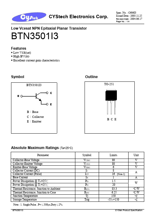
Low Vcesat NPN Epitaxial Planar TransistorBTN3501I3Features• Low V CE (sat) • High BV CEO• Excellent current gain characteristicsSymbol OutlineAbsolute Maximum Ratings (Ta=25°C)Parameter Symbol Limits UnitCollector-Base V oltage V CBO 80 VCollector-Emitter V oltage V CEO 80 V Emitter-Base V oltage V EBO 6 V Collector Current (DC) I C 8Collector Current (Pulse) I CP 16 (Note 1)ABase CurrentI B 1A Power Dissipation @ T A =25℃ P D 1.5Power Dissipation @ T C =25℃P D 20 WThermal Resistance, Junction to Ambient R θJA 83.3 °C/W Thermal Resistance, Junction to Case R θJC 6.25 °C/W Junction Temperature Tj 150 °C Storage TemperatureTstg -55~+150 °CNote : 1. Single Pulse , Pw ≦380µs,Duty ≦2%.BTN3501I3B :BaseC :Collector E :EmitterCharacteristics (Ta=25°C)Conditions Symbol Min. Typ. Max. Unit TestBV CEO(SUS) 80 - - V I C=30mA, I B=0V CE=80V, V BE=0I CES - - 10 µAV EB=5V,I C=0I EBO - - 50 µA*V CE(sat) 1 - 0.1 0.3 V I C=2A, I B=200mA*V CE(sat) 2 - - 0.6 V I C=8A, I B=400mA*V CE(sat) 3 - - 1.5 V I C=5A, I B=50m A*V BE(sat) 1 - - 1.2 V I C=2A, I B=200mA*V BE(sat) 2 - - 1.5 V I C=8A, I B=800mAV CE=1V, I C=100mA *h FE 1 200 - - -*h FE 2 200 - 400 - V CE=1V, I C=2AV CE=1V, I C=4A*h FE3 100 - - -V CE=6V, I C=500mA, f=20MHzf T - 50 -MHzV CB=10V, f=1MHzCob - 130 - pF*Pulse Test : Pulse Width ≤380µs, Duty Cycle≤2% Classification of VCE(sat) 3Rank KA KB N360mV 350mV~900mV 800mV~1500mVRange <Characteristic CurvesTO-251 Dimension*: TypicalInches Millimeters Inches MillimetersDIMMin. Max. Min. Max. DIMMin. Max. Min. Max.A 0.0177 0.0217 0.45 0.55 G 0.2559 - 6.50 -B 0.0354 0.0591 0.90 1.50 H - *0.1811 - *4.60C 0.0177 0.0236 0.45 0.60 I - 0.0354 - 0.90D 0.0866 0.0945 2.20 2.40 J - 0.0315 - 0.80E 0.2520 0.2677 6.40 6.80 K 0.2047 0.2165 5.20 5.50F 0.2677 0.2835 6.80 7.20Notes: 1.Controlling dimension: millimeters. 2.Maximum lead thickness includes lead finish thickness, and minimum lead thickness is the minimum thickness of base material.3.If there is any question with packing specification or packing method, please contact your local CYStek sales office.Material:• Lead: 42 Alloy; solder plating• Mold Compound: Epoxy resin family, flammability solid burning class: UL94V-0Important Notice:• All rights are reserved. Reproduction in whole or in part is prohibited without the prior written approval of CYStek. • CYStek reserves the right to make changes to its products without notice.• CYStek semiconductor products are not warranted to be suitable for use in Life-Support Applications, or systems.• CYStek assumes no liability for any consequence of customer product design, infringement of patents, or application assistance.。
TLV3501AIDR-中文资料
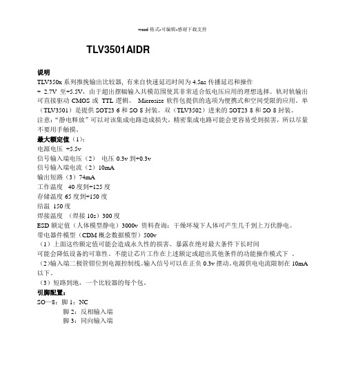
TLV3501AIDR说明TLV350x系列推挽输出比较器, 有来自快速延迟时间为4.5ns传播延迟和操作+ 2.7V至+5.5V,由于超出摆幅输入共模范围使其非常适合低电压应用的理想选择。
轨对轨输出可直接驱动CMOS或TTL逻辑。
Microsize软件包提供的选项为便携式和空间受限的应用。
单(TLV3501)是提供SOT23-6和SO-8封装。
双(TLV3502)进来的SOT23-8和SO-8封装。
注意:“静电释放”可以对该集成电路造成损失,精密集成电路可能会更容易受到损害,所以尽量不要用手触摸。
最大额定值(1):电源电压+5.5v信号输入端电压(2)电压-0.3v到+0.3v信号输入端电流(2)10mA输出短路(3)74mA工作温度-40度到+125度存储温度-65度到+150度结温150度焊接温度(焊接10s)300度ESD额定值(人体模型静电)3000v 资料查询:干燥环境下人体可产生几千到上万伏静电。
带电器件模型(CDM概念数据模型)500v(1)上面这些额定值可能会造成永久性的损害。
暴露在绝对最大条件下长时间可能会降低设备的可靠性。
不能让芯片工作在上述额定或超出其他条件的功能操作模式下。
(2)输入端二极管钳位到电源控制线。
输入信号可以在正负0.3v摆动。
电源供电电流限制在10mA 以下。
(3)短路到地,一个比较器的每个包。
引脚配置:SO—8:脚1:NC脚2:反相输入端脚3:同向输入端脚4:负电源输入端脚5:NC脚6:输出端脚7:正电源输入端脚8:关断信号控制端对于SOT23-6封装由上图可以看出引脚1是由定向的包装标记。
SO-8比SOT23-6封装多了两个NC引脚,NC引脚为空脚,没有内部的电路连接。
电气特性限额适用于在指定温度范围,TA = -40°C至+125°C。
一般情况下在TA=25°C和VS=+2.7V至+5.5 V,除非另有说明。
失调电压:在VCM=0V,IO=0mA条件下失调电压为正负1mv,最大为正负6.5mv温度:-40度到125度偏移量保持在正负5uf/du电源:供电电压保持在2.7v到5.5v偏移量一般保持在100uv/v最大400uv/v输入滞后6mv输入偏置电流:VCM= VCC/2一般偏移量保持在正负2pA最大量正负10pA。
管道制作(中英文对照版)
“批”为同一规格、同一炉号(如焊接,则应用同批焊条、同炉号焊丝和同批焊剂)、同一制度热处理(连续炉或间歇炉温差±14℃(25℉)并配备有完整的温度记录)的材料。
1.2.2“Field Fabricated Piping” shall be defined as all piping assemblies and completely erected piping systems fabricated by the Supplier and/or its field piping erection contractor who has the responsibility for the completely erected piping system. It includes both “in-position” welds and any fabricating operations carried out at the job site.
Contract Title合同标题
Shanghai Secco Petrochemicals Company Limited
上海赛科石油化工有限责任公司
Integrated Project Management Team
一体化项目管理组
Caojing,Shanghai, P R China
SPI3501UH资料
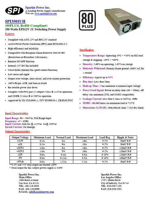
Input CharacteristicsInput Range: 90 ~ 264Vac, Full Range Input Frequency: 47 ~ 63HzInput Current: Max 6A @ 115Vac, 3A@ 230Vac Inrush Current: No damage.Sparkle Power Inc.A Leading Power Supply ManufacturerWeb site: Specification• Temperature Range: Operating: 0°C ~ +50°C on full load; storage & shipping: -20°C ~ +80°C• Humidity: 5-90% on operating, 5-95% on storage•Dielectric Withstand: Primary frame ground 1800V AC for 1 second• Efficiency: typical up to 84% • Rise time: Less than 20ms• Hold-up Time: 17ms minimum at nominal input voltage • Power Good Signal: Power on delay time 100 ~ 500ms, off delay 1ms minimum (TTL and CMOS compatible)• Leakage Current: Less than 3.5mA at 264Vac, 50Hz • MTBF: 100,000 hours on maximum load at +25°C •Dimensions (LxWxH): 190x100x40.5mm /7.5x3.9x1.6inchOutput CharacteristicsOutput Voltage Minimum Load Normal Load Maximum Load Load Reg. Ripple & Noise+3.3V0.5A 8A 16A ± 5% 50mV P-P +5V0.5A 9A 18A ± 5% 50mV P-P +12V11.0A 8A 16A ± 5% 120mV P-P +12V21.0A 8A 16A ± 5% 120mV P-P -12V0.0A 0.4A 0.8A ± 10% 120mV P-P -5V0.0A 0.15A 0.3A ± 10% 100mV P-P +5Vsb0.0A 1.25A 2.5A ± 5% 50mV P-P *+3.3V and +5V total output not exceed 130W* Total output for this subject power supply is 350WSPI3501UH (80PLUS, RoHS Compliant) 350 Watts EPS12V 1U Switching Power Supply Sparkle Power Inc. Main Office1000 Rock Avenue San Jose, CA 95131 TEL: 408-519-8888 FAX: 408-519-9999E-MAIL: info@Features• Complied with ATX 12V and EPS12V standard• Active Power Factor Correction (PFC) meet EN61000-3-2 • High efficiency and reliability•Compatible with European Union Directive 2002/95/EC (Restriction on Hazardous Substances). • Remote ON/OFF function • Internal 12V DC fan included• Noise Killer (thermal fan speed control function) • Low noise and ripple• Output over voltage, short circuit, and over current protection • 100% Hi-pot, ATE, and burn-in tested • Re-settable power shut down•Complies with FCC part 15 subpart J class B 115Vac operation, and CISPR 22 class B at 230Vac operation•Approved by UL/CUL6095-1, TUV EN60950-1, CB,EMC,FCCSparkle Power Inc. Los Angeles Office 17071 Green DriveCity of Industry, CA 91745 TEL: 626-839-7180 FAX: 626-839-3395元器件交易网。
ABB变频器参数表
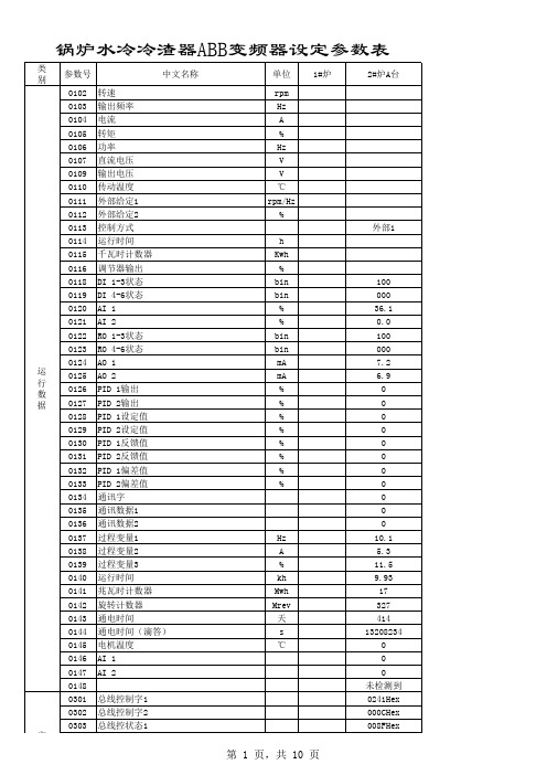
实 际 信 号
第 1 页,共 10 页
锅炉水冷冷渣器ABB变频器设定参数表
类 别 实 际 信 号 参数号 0304 0305 0306 0307 0308 0309 0401 0402 0403 0404 0405 0406 0407 0408 0409 0410 0411 0412 0413 1001 1002 1003 1101 1102 1103 1104 1105 1106 1107 1108 1201 1202 1203 1204 1205 1206 1207 1208 1209 1301 1302 1303 1304 1305 1306 1401 1402 1403 中文名称 总线控状态2 故障字1 故障字2 故障字3 报警字1 报警字2 最后故障 故障时间1 故障时间2 故障时转速 故障时频率 故障时电压 故障时电流 故障时转矩 故障时状态 故障时DI 1-3状态 故障时DI 4-6状态 历史故障1 历史故障2 外部命令1 外部命令2 转向 控制盘给定 外部控制选择 给定值1选择 给定值1下限 给定值1上限 给定值2选择 给定值2下限 给定值2上限 恒速选择 恒速1 恒速2 恒速3 恒速4 恒速5 恒速6 恒速7 定时模式选择 AI 1下限 AI 1上限 AI 1滤波时间 AI 2下限 AI 2上限 AI 2滤波时间 继电器输出1 继电器输出2 继电器输出3 单位 1#炉 2#炉A台 0000Hex 0000Hex 0000Hex 0000Hex 0000Hex 0000Hex
第 2 页,共 10 页
锅炉水冷冷渣器ABB变频器设定参数表
类 别 参数号 1404 1405 1406 1407 1408 1409 1410 1411 1412 1413 1414 1415 1416 1417 1418 1501 1502 1503 1504 1505 1506 1507 1508 1509 1510 1511 1512 1601 1602 1603 1604 1605 1606 1607 1608 1609 1610 2001 2002 2003 2005 2006 2007 2008 2013 2014 2015 2016 继电器1通延时 继电器1断延时 继电器2通延时 继电器2断延时 继电器3通延时 继电器3断延时 继电器输出4 继电器输出5 继电器输出6 继电器4通延时 继电器4断延时 继电器5通延时 继电器5断延时 继电器6通延时 继电器6断延时 AO1赋值 AO1赋值下限 AO1赋值上限 AO1下限 AO1上限 AO2滤波时间 AO2赋值 AO2赋值下限 AO2赋值上限 AO2下限 AO2上限 AO2滤波时间 运行允许 参数锁定 解锁密码 故障复位选择 用户参数切换 本地锁定 参数存储 起动允许1 起动允许2 显示报警 最小转速 最大转速 最大电流 过压控制 欠压控制 最小频率 最大频率 最小转矩选择 最大转矩选择 最小转矩1 最小转矩2 中文名称 单位 s s s s s s 1#炉 2#炉A台 0.0 0.0 0.0 0.0 0.0 0.0 未选择 未选择 未选择 0.0 0.0 0.0 0.0 0.0 0.0 输出频率 0.0 50.0 4.0 20.0 0.1 电流 0.0 15.4 0.0 20.0 0.1 未运行 打开 0 控制盘 未选择 未选择 已存储 未选择 未选择 否 0 1500 23.4 激活 激活(时间) 1.0 50.0 最小转矩1 最大转矩1 -300.0 300.0
电热水器澳洲标准中文版(doc 83页)
电热水器澳洲标准中文版(doc 83页)部门: xxx时间: xxx制作人:xxx整理范文,仅供参考,勿作商业用途澳大利亚/新西兰标准™电热水器第一部分:能量消耗、性能及通用要求标准AS/NZS4692.1:2005本澳大利亚/新西兰联合标准由电热水装置技术委员会(EL-20)编制,分别于2005年9月2日由澳大利亚标准化委员会和新西兰标准化委员会批准。本标准发行日期:2005年9月14日。________________EL-20代理委员会成员单位如下:澳大利亚工商联合会澳大利亚电气和电子制造商协会澳大利亚天然气协会澳大利亚温室效应办公室澳大利亚工业集团澳大利亚不锈钢发展协会新西兰商务部认证中心(澳大利亚)工业、旅游与资源部(英联邦)新西兰能效与节能管理局澳大利亚电气设备符合性测试协会天然气装置供应商协会(新西兰)热交换制造商协会新西兰专业工程师学会新西兰天然气安装工及给排水施工人员协会澳大利亚国家家用电器与设备能效委员会新西兰雇主和制造商协会悉尼自来水公司________________标准随时更新标准是反映科技和系统进步的有效文件,为了保持其通用性,必须定期审查所有标准,并发行新的版本。在各版本之间,可发行修改单。标准还可取消。重要的是,读者自己要保证能使用现行的标准,这些现行标准包括从采购标准以后发行的任何修改单。关于澳大利亚/新西兰联合标准的详细资料,请登录澳大利亚标准网站.au或新西兰标准网站,通过在线目录查找相关标准。另外,两个组织都会发行一份年度打印产品目录,包括所有现行标准的全部详细内容。关于更加频繁的修订、修改和作废的列表或通告,澳大利亚标准协会(Standards Australia)和新西兰标准协会(Standards Newzealand)会提供一些最新的方案。关于这些服务的详细情况,用户宜与其各自国家的标准化组织联系。为了不断进步,我们欢迎提出宝贵的意见,特别鼓励读者及时通知我们任何明显的不准确和模凌两可的内容。请将您的意见按封底上的地址发给澳大利亚标准协会(Standards Australia)和新西兰标准协会(Standards Newzealand)的主管负责人。________________本标准作为DR04388意见草案发行澳大利亚/新西兰标准™电热水器第一部分:能量消耗,性能和通用要求AS 1056.1首次作为AS C316-1957的一部分发行;AS C316-1970修订并重新编成AS 1056-1972;AS 1056-1977修订并重新编成标准AS 1056.1-1985;AS 1056.2 首次发行于1985年;AS 1056.3首次作为标准AS C316-1970的一部分发行;AS C316-1970修订并重新编成AS 1056-1972;AS 1056-1977修订并重新编成AS 1056.3-1985的一部分; 1991年第二版; AS 1056.1-1991、AS 1056.2-1985和AS 1056.3-1991修订、合并重新编成标准AS/NZS4692.1:2005版权所有© 澳大利亚标准/新西兰标准版权所有,翻印必究。未经出版商的书面许可,不得以任何形式或通过任何手段【电子的或机械的(包括影印本)】复制本著作的任何部分。澳大利亚标准协会(Standards Australia)(地址:GPO Box 476,Sydney,NSW 2001)和新西兰标准化协会(地址:Private Bag 2439,Wellington 6020)联合发布。ISBN0 7337 6895 4序言本标准由澳大利亚标准协会(Standards Australia)/新西兰标准协会(Standards Newzealand)联合委员会 EL-020(电热水器具)编制,最终在固定的日期代替了AS 1056.1-1990 《储水式热水器-通用要求》、标准AS 1056.2-1985水式热水器-带有单一外壳的热水器的具体要求》和AS 1056.3-1991《储水式热水器-带有合成外壳的热水器的具体要求》。本标准旨在于固定日期最终代替NZS4602:1998《低压铜储热式电热水器》和NZS4606的第一部分至第三部分以及AS 1056的第一部分至第三部分的新西兰改编本。本标准属于下列标准的一部分:标准AS/NZS4692 电热水器;4692.1 第一部分:能量消耗,性能和通用要求;4692.2 第二部分:最低能量性能标准(MEPS)要求和能量标识。标准AS/NZS4692系列标准的总体目标是促进热水器的高质量、性能和能效水平。标准AS/NZS4692 的各部分汇总如下:(a)第一部分包括试验步骤、最低性能要求以及热水器的其它要求,还包括电动储水式热水器的确定恒定的热损失修订后的试验方法以及确定热水出水量和混合热水出水量的方法。(b)第二部分包括电动储水式热水器和电动热交换式热水器的最低能量性能标准(MEPS)要求,包括了电动储水式热水器“顶级节能奖”标识的具体细则,其结构适合现行立法参考,并与第一部分一起使用。修订后的标准AS/NZS4692标准现在包括以前AS 1361标准包括的热交换式热水器的要求,政府旨在引进冷冻水和沸水分配器的最低能量性能标准(MEPS)水平,这将包括在今后的标准AS/NZS4692.2修正或修订中。冷冻水和沸水分配器的试验方法将作为本标准单独的一部分。为了按照标准AS/NZS4692.2的要求进行管制,按照本标准或AS 1056.1的修改单5或AS 1361的修改单(适合时)的热损失试验在通知之日前具有同等效力,之后只能按照本标准进行试验。所有图表中附注的强制条款的明确声明被视为本标准的要求。为了定义附录的应用场合,本标准已经采用了术语“规范性附录”和“资料性附录”。“规范性附录”属于标准的有机组成部分,而“资料性附录”仅供参考并且属于指导性附录。目录页次第一节范围和总则1.1 范围 (11)1.2 应用 (11)1.3 参考文件 (12)1.4 定义 (14)1.5 其它规范的符合性 (20)第二节设计和构造要求2.1 本节范围 (21)2.2 强度 (21)2.3 与水接触的材料和零部件 (23)2.4 水管件 (24)2.5 水管子 (24)2.6 排水设施 (25)2.7 水套管 (25)2.8 保护支架 (25)2.9 绝热 (26)2.10 维护保养设施 (26)2.11 包装 (27)第三节电气零部件3.1 本节范围 (28)3.2 加热单元 (28)3.3 温度控制装置和热保护装置 (30)第四节标志和使用说明4.1 本节范围 (32)4.2 标志和使用说明 (32)4.3 安装说明 (32)第五节热水器和容器贮存的具体要求5.1 本节范围 (34)5.2 热水出水量/标称量 (34)5.3 水密性 (34)5.4 带有合成外壳的热水器 (35)5.5 有单一外壳的加热器 (41)5.6 自带进水箱的加热器 (43)5.7 恒温控制器 (45)5.8 增压式加热单元 (46)5.9 标记和说明须知 (47)第六节热交换水加热器的具体要求6.1 本节范围 (48)6.2 热水出水量/标称容量 (48)6.3 强度 (48)6.4 自带进水箱的加热器 (49)6.5 恒温控制器-表面接触式 (49)6.6 标志和使用说明 (49)6.7 产品规格 (49)附录A 证实符合本标准的手段 (50)B 标准化的试验条件 (61)C 确定恒定的热损失 (73)D 确定热水出水量 (81)E 混合热水出水量 (87)F 储水式热水器的典型规格 (94)G 不透气容器的压力疲劳测试 (100)H 铜、低压热水器外壳的构造细则 (102)I 配置和确定空气温度传感器的时间常数 (107)J 线性回归 (111)K 水的密度 (113)L 试验室配置 (116)M 确定玻璃状搪瓷上釉衬料可溶性的方法 (119)N 确定水箱热损失的误差 (123)澳大利亚标准/新西兰标准_________澳大利亚/新西兰标准电热水器_________第一部分:能量消耗、性能和总体要求_________第一节范围和总则1.1 范围本标准规定了下列类型电热水器的试验方法以及性能和构造要求。(a)额定热水出水量达到630L或者标称容量达到710L的储水式热水器,包括太阳能、热泵和间接加热系统的储水零部件。(b)加热储水容积达710L的热交换式热水器;(c)使用电阻性加热作为主要能源的热水器,但是热损失和出水的试验方法还是适用于其它类型的热水器(例如太阳能热水器和热泵)。注:1.打算采购超出本标准范围的热水器建议将本标准的相关要求包括在其规范中,典型的产品规格型式见附录F。2.本标准的试验方法还可应用于不在本标准范围内的产品规格。1.2 应用证明符合本标准要求的手段应符合附录A的规定。标准化的试验条件应符合附录B的规定。确认标准的热损失应符合附录C的规定。1.3 参考文件本标准参考了下列文件:AS1210 压力容器1308 电热水器-恒温控制器和热保护切断装置1357 主要用于热水系统的阀门1357.1 第一部分:保护阀门1357.2 第二部分:控制阀门1361 电动热交换式热水器-家用1432 给排水、燃气管件和排水应用的铜管1566 铜和铜合金-轧制扁材1722 惠氏螺纹牙样的管螺纹1722.1 第一部分:密封管螺纹1722.2 第二部分:紧固管螺纹2239 流电(牺牲)的印迹保护2812 金属铆焊-术语词汇表AS3498 给排水产品的授权要求 -热水器和热水储水箱3688 供水-金属管件和接头AS/NZS3161 审批和试验规范-恒温控制器和能量调节器3500 给排水3500.1 第一部分:水设施3500.4 第四部分:加热水设施3823 电器装置的性能-空气调节装置和加热泵3823.1.1 第一部分.1 试验方法-非管道式空气调节装置和加热泵-性能的测试和标定等级4020 与饮用水接触的产品测试4692 电热水器4692.2 第二部分:最低能量性能标准(MEPS)要求和贴标识60335 家用和类似电器装置-安全60335.1 第一部分:通用要求(IEC 60335-1:2001,MOD)60335.2.15 第二部分.15:液体加热器具的特定要求60335.2.21 第二部分.21:特定要求-储水式热水器HB 18 第三方认证和鉴定指南HB 18.28 (ISO/IEC 导则28)产品型号第三方认证方案的总则NZS3501 水、燃气和卫生系统用铜管规范4602 低压铜热储水式电热水器4606 储水式热水器6214 家用热储水式电热水器的恒温控制器和热保护切断装置(只用于交流电)ASTMA 240 铬和铬-镍不锈钢的标准规范S31600 压力容器和通用应用场合的板材和带材BS21 压紧接头用螺纹连接的管材和管件的管螺纹规范。BS EN1652 铜和铜合金-通用应用场合的板材、带材和圆材1044 金属铜焊料BS EN ISO228-1 压紧接头不用螺纹连接的管螺纹公差和牌号ISO/IEC17025 测试和校准实验室胜任能力的通用要求NZBC 新西兰建筑规范G12 给水设施1.4 定义下列术语和定义适用本标准。1.4.1 空气源热泵式热水器由带有一个空气源蒸发器的热泵和一个将热量输送至热水储水式容器的冷凝器组成的一种系统。环境能量从大气的潜伏热和显热收集。1.4.2 粘合型釉瓷涂层附着在容器主要构件上并且能耐受连续暴露至热水的一种涂层,粘合性釉瓷涂层的种类如下:(a)X级涂层 -旨在用于水温不超过70 ℃的粘合型涂层;(b)Y级-溶解性低于X级涂层的粘合型涂层,旨在更加能耐受温度达到70 ℃的水的溶解作用或者在温度超过70 ℃时使用。1.4.3 水套容器四周的夹套及其绝热层。1.4.4 容器热水(或热交换式热水器的传热液)在其中加热、加热和储热或者储热的容器(包括配件)。1.4.5 保护支架用于支撑容器或容器配件的支架、支撑物或约束装置。1.4.6 容积式热水器水从底部或者底部附近进入容器且当其从顶部或顶部抽出时排出热水的一种储水式热水器。容积式热水器有以下几种类型:(a)水槽供水式热水器:一种透气容积式热水器,从分体安装的给水箱供水,给水箱的水位自动保持。(b)自由出水式热水器:一种装有常开出口的容积式热水器,热水根据储水容器的容积排出,流量由进水给水管路上阀门控制。(c)低压热水器:专门设计成工作压力不超过120kPa的一种容积式热水器,可采用透气式,也可采用不透气式。(d)总水源压力式热水器:一种非透气容积式热水器,旨在直接连接至给水系统,并且(i)在澳大利亚,温度/泄压阀(安全阀)的设定值不超过1400KPa;(ii)在新西兰,设计的工作压力超过120KPa。(e)侧进水式热水器:一种低压热水器,带有自由水面,其进口从接在热水器侧面的给水箱供水,热水从位于自由水面下方的出水口抽出。(f)自带水箱的热水器:无自由水面的低压热水器,其中进水通过附着固定在热水器上的给水箱供给。
GBA口袋妖怪修改商店卖的东西

0084 怀旧信封 レトロメール RETRO MAIL
0085 树果01 クラボのみ CHERI BERRY
0086 树果02 カゴのみ CHESTO BERRY
0087 树果03 モモンのみ PECHA BERRY
0088 树果04 チーゴのみ RAWST BERRY
009B 树果23 タポルのみ QUALOT BERRY
009C 树果24 ロメのみ HONDEW BERRY
009D 树果25 ウブのみ GREPA BERRY
009h 树果26 マトマのみ TAMATO BERRY
009F 树果27 モコシのみ CORNN BERRY
00A0 树果28 ゴスのみ MAGOST BERRY
0024 全PP增加剂 ピーピーエイダー ELIXIR
0025 全PP回复剂 ピーピーマックス MAX ELIXIR
0026 芬氏煎饼 フエンせんべい LAVA COOKIE
0027 蓝色玻璃 あおいビードロ BLUE FLUTE
0028 黄色玻璃 きいろビードロ YELLOW FLUTE
000C 纪念球 プレミアボール PREMIER BALL
000D 疗伤药 キズぐすり POTION
000E 消毒药 どくけし ANTIDOTE
000F 烧伤药 やけどなおし BURN HEAL
0010 冻伤药 こおりなおし ICE HEAL
0011 苏醒药 ねむけざまし AWAKENING
00C7 金钢外套 メタルコート METAL COAT
00C8 剩饭 たべのこし LEFTOVERS
GBPC3501中文资料
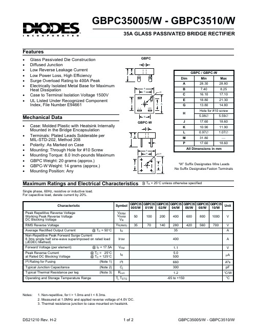
GBPC35005/W - GBPC3510/W35A GLASS PASSIVATED BRIDGE RECTIFIERFeatures“W” Suffix Designates Wire LeadsNo Suffix Designates Faston TerminalsGBPC-WGBPCa Maximum Ratings and Electrical Characteristics@ T A = 25°C unless otherwise specifiedMechanical DataSingle phase, 60Hz, resistive or inductive load.For capacitive load, derate current by 20%.Notes:1. Non-repetitive, for t > 1.0ms and t < 8.3ms.2. Measured at 1.0MHz and applied reverse voltage of 4.0V DC.3. Thermal resistance junction to case mounted on heatsink.·Glass Passivated Die Construction ·Diffused Junction·Low Reverse Leakage Current ·Low Power Loss, High Efficiency ·Surge Overload Rating to 400A Peak·Electrically Isolated Metal Base for Maximum Heat Dissipation·Case to Terminal Isolation Voltage 1500V ·UL Listed Under Recognized Component Index, File Number E94661·Case: Molded Plastic with Heatsink Internally Mounted in the Bridge Encapsulation ·Terminals: Plated Leads Solderable per MIL-STD-202, Method 208·Polarity: As Marked on Case·Mounting: Through Hole for #10 Screw·Mounting Torque: 8.0 Inch-pounds Maximum ·GBPC Weight: 20 grams (approx.)·GBPC-W Weight: 14 grams (approx.)·Mounting Position: Any0.010.11.01010000.40.8 1.0 1.6 1.80.60.2 1.2 1.4I ,I N S T A N T A N E O U S F O R W A R D C U R R E N T (A )F V ,INSTANTANEOUS FORWARD VOLTAGE (V)Fig.2Typical Forward Characteristics (per element)F100200300400110100I ,P E A K F W D .S U R G E C U R R E N T (A )F S M NUMBER OF CYCLES AT 60Hz Fig.3Max Non-Repetitive Surge Current1010010000.11.010100C ,C A P A C I T A N C E (p F )j V ,REVERSE VOLTAGE (V)Fig.4TypicalJunction Capacitance (per element)R 0.010.11.01010040206080100120140I ,I N S T A N T A N E O U S R E V E R S E C U R R E N T (µA )R PERCENT OF RATED PEAK REVERSE VOLTAGE (%)Fig.5Typical Reverse Characteristics (per element)10200255075100125150I ,A V E R A G E F O R W A R D C U R R E NT (A )F T ,CASE TEMPERATURE (°C)Fig.1Forward Current Derating Curve C 3040。
堡文重型滤芯用户指南:适用于菲亚特F-250、F-350商业汽车说明书

BALDWIN
PA4073 PA2233
PA4171
CA5369
PA4433
–
RS3517 RS3517XP PA4110 (F-750 Only)
RS3517 RS3517XP PA4110 (F-750 Only)
CA5514 RS3517 RS3517XP
CA5514
RS3517 RS3517XP
F-650 Super Duty, F-750 (2008-on)
Cummins ISB (5.9L) Eng.
F-650, F-750 (To 2007)
Cummins ISB (5.9L) Eng.
F-650, F-750
F-650 F-650, F-750 F-650, F-750
Cummins ISB 200 (6.7L) Eng.
PF7852 KIT
4C2Z-9N-184-BA Set of 2 Fuel Elements
IHC T444E (7.3L) Eng. IHC VT365 (6.0L) Eng. V8-406 (6.7L) FI Turbo Diesel Eng.
BF1222-O BF1222 BF1222-SP PF7678
F2TZ-9N-184-A F2TZ-9N-184-A E8TZ-9N-184-A F4TZ-9N-184-A
BC3Z-9601-A Panel Air Element
FUEL F Super Duty
V8-445 (7.3L) Turbo Diesel Eng.
E-450 Super Duty
V8-363 (6.0L) FI Turbo Diesel Eng.
F-450, F-550 Super Duty
FDA变更指南中英文

Guidance for IndustryChanges to an ApprovedNDA or ANDA已批准申请的新药变更指南U.S. Department of Health and Human ServicesFood and Drug AdministrationCenter for Drug Evaluation and Research (CDER)April 2004CMCRevision 1I. INTRODUCTION AND BACKGROUNDThis guidance provides recommendations to holders of new drug applications (NDAs) and abbreviated new drug applications (ANDAs) who intend to make post approval changes in accordance with section 506A of the Federal Food, Drug, and Cosmetic Act (the Act) and § 314.70 (21 CFR 314.70). The guidance covers recommended reporting categories for postapproval changes for drugs other than specified biotechnology and specified synthetic biological products. It supersedes the guidance of the same title published November 1999. Recommendations are provided for postapproval changes in (1) components and composition, (2) manufacturing sites, (3) manufacturing process, (4) specifications, (5) container closure system, and (6) labeling, as well as (7) miscellaneous changes and (8) multiple related changes.本指南给打算将已批准变更的新药上市申请和新药报审简表申请的持有者提供建议,使其按照联邦食品、药品、化妆品法案的506A部分和§ 314.70 (21 CFR 314.70)。
LT3501EFE#PBF资料
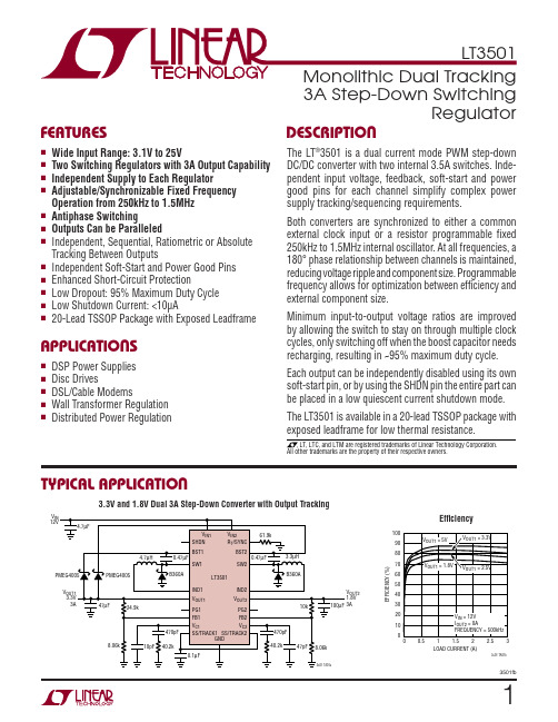
33501fbELECTRICAL CHARACTERISTICS Note 1: Stresses beyond those listed under Absolute Maximum Ratings may cause permanent damage to the device. Exposure to any Absolute Maximum Rating condition for extended periods may affect device reliability and lifetime.Note 2: The LT3501EFE is guaranteed to meet performance specifi cations from 0°C to 125°C junction temperature. Specifi cations over the –40°C to 125°C operating junction temperature range are assured by design, characterization and correlation with statistical process controls. TheLT3501IFE is guaranteed and tested over the full –40°C to 125°C operating junction temperature range.Note 3: Minimum input voltage is defi ned as the voltage where internal bias lines are regulated so that the reference voltage and oscillator remain PARAMETERCONDITIONSMIN TYP MAX UNITS Error Amplifi er Source Current Ch 1/2V FB1/2 = 0.6V, V VC1/2 = 1V 101525µA Error Amplifi er Sink Current Ch 1/2V FB1/2 = 1V, V VC1/2 = 1V 152030µA Error Amplifi er High Clamp Ch 1/2V FB1/2 = 0.7V1.752.0 2.25V Error Amplifi er Switching Threshold Ch 1/2V OUT1/2 = 5V, R T /SYNC = 133k 0.50.7 1.0V Soft-Start Source Current Ch 1/2V FB1/2 = 0.6V, V SS1/2 = 0.4V ●2.53.254µA Soft-Start V OH Ch 1/2V FB1/2 = 0.9V1.922.4V Soft-Start Sink Current Ch 1/2V FB1/2 = 0.6V, V SS1/2 = 1V 2006001000µA Soft-Start V OL Ch 1/2V FB1/2 = 0V5080125mV Soft-Start to Feedback Offset Ch 1/2V VC1/2 = 1V, V SS1/2 = 0.4V ●–16016mV Soft-Start Sink Current Ch 1/2 POR V SS1/2 = 0.4V (Note 4), V VC = 1V 0.5 1.52mA Soft-Start POR Threshold Ch 1/2V FB1/2 = 0V (Note 4)5580105mV Soft-Start Switching Threshold Ch 1/2V FB1/2 = 0V305070mV Power Good Leakage Ch 1/2V FB1/2 = 0.9V, V PG1/2 = 25V, V VIN1/2 = 25V 01µA Power Good Threshold Ch 1/2V FB1/2 Rising, PG1/2 = 20k to 5V ●879093%Power Good Hysteresis Ch 1/2V FB1/2 Falling, PG1/2 = 20k to 5V 203050mV Power Good Sink Current Ch 1/2V FB1/2 = 0.65V, V PG1/2 = 0.4V 4008001200µA Power Good Shutdown Sink Current Ch 1/2V VIN1/2 = 2V, V FB1/2 = 0V, V PG1/2 = 0.4V 1050100µA R T /SYNC Reference Voltage V FB1/2 = 0.9V, I RT/SYNC = –40µA0.930.9751V Switching FrequencyR T /SYNC = 133k, V FB1/2 = 0.6V, V BST1/2 = V SW + 3VR T /SYNC = 15.4k, V FB1/2 = 0.6V, V BST1/2 = V SW + 3V 2001.22501.53001.8kHz MHz Switching Phase Angle Ch A to Ch B R T /SYNC = 133k, V FB1/2 = 0.6V, V BST1/2 = V SW + 3V 120180210Deg Minimum Boost for 100% Duty Cycle Ch 1/2V FB1/2 = 0.7V, I RT/SYNC = –35µA (Note 5), V OUT = 0V 1.72V SYNC Frequency RangeV BST1/2 = V SW + 3V2501500kHz SYNC Switching Phase Angle Ch A to Ch B SYNC Frequency = 250kHz, V BST1/2 = V SW + 3V 120180210Deg IND + V OUT Current Ch 1/2V VOUT1/2 = 0V, V FB1/2 = 0.9V V VOUT1/2 = 5V407001001µA µA IND to V OUT Maximum Current Ch 1/2V VOUT1/2 = 0.5V (Note 6), V FB1/2 = 0.7V, V BST1/2 = 20V V VOUT1/2 = 5V (Note 6), R T /SYNC = 133k, V BST1/2 = 20V 3.253.54455A A Switch Leakage Current Ch 1/2V SW1/2 = 0V, V VIN1/2 = 25V●050µA Switch Saturation Voltage Ch 1/2I SW1/2 = 3A, V BST1/2 = 20V, V FB1/2 = 0.7V ●250600mV Boost Current Ch 1/2I SW1/2 = 3A, V BST1/2 = 20V, V FB1/2 = 0.7V 2560100mA Minimum Boost Voltage Ch 1/2I SW1/2 = 3A, V BST1/2 = 20V, V FB1/2 = 0.7V1.42.5Vconstant. Actual minimum input voltage to maintain a regulated output will depend upon output voltage and load current. See Applications Information.Note 4: An internal power-on reset (POR) latch is set on the positive transition of the SHDN pin through its threshold. The output of the latch activates current sources on each SS pin which typically sink 1.5mA, discharging the SS capacitor. The latch is reset when both SS pins are driven below the soft-start POR threshold or the SHDN pin is taken below its threshold.Note 5: To enhance dropout operation, the output switch will be turned off for the minimum off time only when the voltage across the boost capacitor drops below the minimum boost for 100% duty cycle threshold.The ● denotes the specifi cations which apply over the full operatingtemperature range, otherwise specifi cations are at T J = 25°C. V VIN1/2 = 15V, V BST1/2 = open, V RT/SYNC = 2V, V VOUT1/2 = open, unless otherwise specifi ed.This indicates that the output is overloaded and current is pulled from the SS pin, reducing the regulation point. FB1/FB2 (Pins 17, 14): The FB pin is the negative input to the error amplifi er. The output switches regulate this pin to 0.8V, with respect to the exposed ground pad. Bias current fl ows out of the FB pin.SHDN (Pin 15): The shutdown pin is used to turn off both channels and control circuitry to reduce quiescent current to a typical value of 9µA. The accurate 1.28V threshold and input current hysteresis can be used as an undervoltage lockout, preventing the regulator from operating until the input voltage has reached a predetermined level. Force the SHDN pin above its threshold or let it fl oat for normal operation.R T/SYNC (Pin 16): This R T/SYNC pin provides two modes of setting the constant switch frequency. Connecting a resistor from the R T/SYNC pin to ground will set the R T/SYNC pin to a typical value of 0.975V. The resultant switching frequency will be set by the resistor value. The minimum value of 15.4k and maximum value of 133k sets the switching frequency to 1.5MHz and 250kHz respectively.Driving the R T/SYNC pin with an external clock signal will synchronize the switch to the applied frequency. Synchro-nization occurs on the rising edge of the clock signal after the clock signal is detected, with switch 1 in phase with the synchronization signal. Each rising clock edge initiates an oscillator ramp reset. A gain control loop servos the oscillator charging current to maintain a constant oscillator amplitude. Hence, the slope compensation and channel phase relationship remain unchanged. If the clock signal is removed, the oscillator reverts to resistor mode and reapplies the 0.975V bias to the R T/SYNC pin after the synchronization detection circuitry times out. The clock source impedance should be set such that the current out of the R T/SYNC pin in resistor mode generates a frequency roughly equivalent to the synchronization frequency. BST1/BST2 (Pins 20, 11): The BST pin provides a higher than V IN base drive to the power NPN to ensure a low switch drop. A comparator to V IN imposes a minimum off time on the SW pin if the BST pin voltage drops too low. Forcing a SW off time allows the boost capacitor to recharge.Exposed Pad (Pin 21): GND. The Exposed Pad GND pin is the only ground connection for the device. The Exposed Pad should be soldered to a large copper area to reduce thermal resistance. The GND pin is common to both chan-nels and also serves as small-signal ground. For ideal operation all small-signal ground paths should connect to the GND pin at a single point, avoiding any high current ground returns.PIN FUNCTIONS83501fbwill be generated at the incoming frequency on the rising edge of the synchronization pulse with switch 1 in phase with the synchronization signal. In addition, the internal slope compensation will be automatically adjusted to pre-vent subharmonic oscillation during synchronization. The two regulators are constant frequency, current mode step-down converters. Current mode regulators are con-trolled by an internal clock and two feedback loops that control the duty cycle of the power switch. In addition to the normal error amplifi er, there is a current sense amplifi er that monitors switch current on a cycle-by-cycle basis. This technique means that the error amplifi er commands current to be delivered to the output rather than voltage.A voltage fed system will have low phase shift up to the resonant frequency of the inductor and output capacitor, then an abrupt 180°, shift will occur. The current fed sys-tem will have 90° phase shift at a much lower frequency, but will not have the additional 90° shift until well beyond the LC resonant frequency. This makes it much easier to frequency compensate the feedback loop and also gives much quicker transient response.The Block Diagram in Figure 1 shows only one of the switching regulators whose operation will be discussed below. The additional regulator will operate in a similar manner with the exception that its clock will be 180° out of phase with the other regulator.When, during power up, the POR signal sets the soft-start latch, both SS pins will be discharged to ground to ensure proper start-up operation. When the SS pin voltage drops below 80mV, the V C pin is driven low disabling switching and the soft-start latch is reset. Once the latch is reset the soft-start capacitor starts to charge with a typical value of 3.25µA.As the voltage rises above 80mV on the SS pin, the V C pin will be driven high by the error amplifi er. When the volt-age on the V C pin exceeds 0.7V, the clock set-pulse sets the driver fl ip-fl op which turns on the internal power NPN switch. This causes current from V IN, through the NPN switch, inductor and internal sense resistor, to increase. When the voltage drop across the internal sense resistor exceeds a predetermined level set by the voltage on the V C pin, the fl ip-fl op is reset and the internal NPN switch is turned off. Once the switch is turned off the inductor will drive the voltage at the SW pin low until the external Schottky diode starts to conduct, decreasing the current in the inductor. The cycle is repeated with the start of each clock cycle. However, if the internal sense resistor voltage exceeds the predetermined level at the start of a clock cycle, the fl ip-fl op will not be set resulting in a further decrease in inductor current. Since the output current is controlled by the V C voltage, output regulation is achieved by the error amplifi er continually adjusting the V C pin voltage.The error amplifi er is a transconductance amplifi er that compares the FB voltage to the lowest voltage present at either the SS pin or an internal 0.8V reference. Compensa-tion of the loop is easily achieved with a simple capacitor or series resistor/capacitor from the V C pin to ground. Since the SS pin is driven by a constant current source, a single capacitor on the soft-start pin will generate controlled linear ramp on the output voltage.If the current demanded by the output exceeds the maxi-mum current dictated by the V C pin clamp, the SS pin will be discharged, lowering the regulation point until the output voltage can be supported by the maximum current. When overload is removed, the output will soft-start from the overload regulation point.V IN1 undervoltage detection or thermal shutdown will set the soft-start latch, resulting in a complete soft-start sequence.The switch driver operates from either the V IN or BST volt-age. An external diode and capacitor are used to generate a drive voltage higher than V IN to saturate the output NPN and maintain high effi ciency. If the BST capacitor voltage is suffi cient, the switch is allowed to operate to 100% duty cycle. If the boost capacitor discharges towards a level insuffi cient to drive the output NPN, a BST pin compara-tor forces a minimum cycle off time, allowing the boost capacitor to recharge.A power good comparator with 30mV of hysteresis trips at 90% of regulated output voltage. The PG output is an open-collector NPN that is off when the output is in regu-lation allowing a resistor to pull the PG pin to a desired voltage.BLOCK DIAGRAM103501fbeither clamp the input voltage or dampen the tank circuit by adding a lossy capacitor in parallel with the ceramic capacitor. For details, see Application Note 88.Output Capacitor SelectionTypically step-down regulators are easily compensated with an output crossover frequency that is 1/10 of the switch-ing frequency. This means that the time that the output capacitor must supply the output load during a transient step is ~2 or 3 switching periods. With an allowable 5% drop in output voltage during the step, a good starting value for the output capacitor can be expressed by:CMax Load StepFrequency V VOUTOUT =•.•005Example:V OUT = 3.3V, Frequency = 1MHz, Max Load Step = 3ACe V FVOUT ==2160053312•.•.µThe calculated value is only a suggested starting value. Increase the value if transient response needs improvement or reduce the capacitance if size is a priority.The output capacitor fi lters the inductor current to generate an output with low voltage ripple. It also stores energy in order to satisfy transient loads and to stabilize the LT3501’s control loop. The switching frequency of the LT3501 deter-mines the value of output capacitance required. Also, the current mode control loop doesn’t require the presence of output capacitor series resistance (E SR). For these reasons, you are free to use ceramic capacitors to achieve very low output ripple and small circuit size.Estimate output ripple with the following equations:V RIPPLE = ∆I L/(8f C OUT) for ceramic capacitors,andV RIPPLE = ∆I L ESR for electrolytic capacitors (tantalum and aluminum)where ∆I L is the peak-to-peak ripple current in the inductor.The RMS content of this ripple is very low, and the RMS current rating of the output capacitor is usually not of concern.Another constraint on the output capacitor is that it must have greater energy storage than the inductor; if the stored energy in the inductor is transferred to the output, you would like the resulting voltage step to be small compared to the regulation voltage. For a 5% overshoot, this require-ment becomesC LIVOUTLIMOUT>⎛⎝⎜⎞⎠⎟102Finally, there must be enough capacitance for good transient performance. The last equation gives a good starting point. Alternatively, you can start with one of the designs in this data sheet and experiment to get the desired performance. This topic is covered more thoroughly in the section on loop compensation.The high performance (low E SR), small size and robustness of ceramic capacitors make them the preferred type for LT3501 applications. However, all ceramic capacitors are not the same. As mentioned above, many of the high value capacitors use poor dielectrics with high temperature and voltage coeffi cients. In particular, Y5V and Z5U types lose a large fraction of their capacitance with applied voltage and temperature extremes. Because the loop stability and transient response depend on the value of C OUT, you may not be able to tolerate this loss. Use X7R and X5R types. You can also use electrolytic capacitors. The ESRs of most aluminum electrolytics are too large to deliver low output ripple. Tantalum and newer, lower ESR organic electrolytic capacitors intended for power supply use, are suitable and the manufacturers will specify the ESR. The choice of capacitor value will be based on the ESR required for low ripple. Because the volume of the capacitor determines its ESR, both the size and the value will be larger than a ceramic capacitor that would give you similar ripple per-formance. One benefi t is that the larger capacitance may give better transient response for large changes in load current. Table 2 lists several capacitor vendors.APPLICATIONS INFORMATION153501fb163501fbTable 2VENDOR TYPE SERIESTaiyo Yuden Ceramic X5R, X7R AVX Ceramic X5R, X7RTantalum KemetTantalum TA Organic AL Organic T491, T494, T495T520A700Sanyo TA/AL Organic POSCAP Panasonic AL Organic SP CAP TDKCeramic X5R, X7RCatch DiodeThe diode D1 conducts current only during switch off time. Use a Schottky diode to limit forward voltage drop to increase effi ciency. The Schottky diode must have a peak reverse voltage that is equal to regulator input voltage and sized for average forward current in normal operation. Average forward current can be calculated from:I I V V V D AVG OUTININ OUT ()•–=()The only reason to consider a larger diode is the worst-case condition of a high input voltage and shorted output. With a shorted condition, diode current will increase to a typical value of 4A, determined by the peak switch current limit of the LT3501. This is safe for short periods of time, but it would be prudent to check with the diode manu-facturer if continuous operation under these conditions can be tolerated.BST Pin ConsiderationsThe capacitor and diode tied to the BST pin generate a voltage that is higher than the input voltage. In most cases a 0.47µF capacitor and fast switching diode (such as the CMDSH-3 or FMMD914) will work well. Almost any type of fi lm or ceramic capacitor is suitable, but the ESR should be <1Ω to ensure it can be fully recharged during the off time of the switch. The capacitor value can be approximated by: C I DCB V V fBST OUT MAX OUT BST MIN =()()()••–•where I OUT(MAX) is the maximum load current, and V BST(MIN) is the minimum boost voltage to fully saturate the switch.Figure 5 shows four ways to arrange the boost circuit. The BST pin must be more than 1.4V above the SW pin for full effi ciency. Generally, for outputs of 3.3V and higher the standard circuit (Figure 5a) is the best. For outputs between 2.8V and 3.3V, replace the D2 with a small Schottky diode such as the PMEG4005. For lower output voltages the boost diode can be tied to the input (Figure 5b). The circuit in Figure 5a is more effi cient because the BST pin current comes from a lower voltage source. Fig-ure 5c shows the boost voltage source from available DC sources that are greater than 3V. The highest effi ciency is attained by choosing the lowest boost voltage above 3V. For example, if you are generating 3.3V and 1.8V and the 3.3V is on whenever the 1.8V is on, the 1.8V boost diode can be connected to the 3.3V output. In any case, you must also be sure that the maximum voltage at the BST pin is less than the maximum specifi ed in the Absolute Maximum Ratings section.The boost circuit can also run directly from a DC voltage that is higher than the input voltage by more than 3V, as in Figure 5d. The diode is used to prevent damage to the LT3501 in case V X is held low while V IN is present. The circuit saves several components (both BST pins can be tied to D2). However, effi ciency may be lower and dissipa-tion in the LT3501 may be higher. Also, if V X is absent, the LT3501 will still attempt to regulate the output, but will do so with very low effi ciency and high dissipation because the switch will not be able to saturate, dropping 1.5V to 2V in conduction.The minimum input voltage of an LT3501 application is limited by the minimum operating voltage (<3V) and by the maximum duty cycle as outlined above. For proper start-up, the minimum input voltage is also limited by the boost circuit. If the input voltage is ramped slowly, or the LT3501 is turned on with its SS pin when the output is already in regulation, then the boost capacitor may not be fully charged. Because the boost capacitor is charged with the energy stored in the inductor, the circuit will rely on some minimum load current to get the boost circuit running properly. This minimum load will depend onAPPLICATIONS INFORMATIONAt power-up, a reset signal sets the soft-start latch and discharges both SS pins to approximately 0V to ensure proper start-up. When both SS pins are fully discharged the latch is reset and the internal 3.25µA current source starts to charge the SS pin.When the SS pin voltage is below 50mV, the V C pin is pulled low which disables switching. This allows the SS pin to be used as an individual shutdown for each channel.As the SS pin voltage rises above 50mV, the V C pin is re-leased and the output is regulated to the SS voltage. When the SS pin voltage exceeds the internal 0.8V reference, the output is regulated to the reference. The SS pin voltage will continue to rise until it is clamped at 2V.In the event of a V IN1 undervoltage lockout, the SHDN pin driven below 1.28V, or the internal die temperature exceeding its maximum rating during normal operation, the soft-start latch is set, triggering a start-up sequence.In addition, if the load exceeds the maximum output switch current, the output will start to drop causing the V C pin clamp to be activated. As long as the V C pin is clamped, the SS pin will be discharged. As a result, the output will be regulated to the highest voltage that the maximum output current can support. For example, if a 6V output is loaded by 1Ω the SS pin will drop to 0.53V, regulating the output at 4V ( 4A • 1Ω ). Once the overload condition is removed, the output will soft-start from the temporary voltage level to the normal regulation point.Since the SS pin is clamped at 2V and has to discharge to 0.8V before taking control of regulation, momentary overload conditions will be tolerated without a soft-start recovery. The typical time before the SS pin takes control is:tC VA SS CONTROLSS()•.=12700µPower Good IndicatorsThe PG pin is the open-collector output of an internal comparator. The comparator compares the FB pin voltage to 90% of the reference voltage with 30mV of hysterisis. The PG pin has a sink capability of 800µA when the FB pin is below the threshold and can withstand 25V when the threshold is exceeded. The PG pin is active (sink capability is reduced in shutdown and undervoltage lockout mode) as long as the V IN1 pin voltage exceeds 1V.Output Tracking/SequencingComplex output tracking and sequencing between chan-nels can be implemented using the LT3501’s SS and PG pins. Figure 9 shows several confi gurations for output tracking/sequencing for a 3.3V and 1.8V application. Independent soft-start for each channel is shown in Figure 9a. The output ramp time for each channel is set by the soft-start capacitor as described in the soft-start section.Ratiometric tracking is achieved in Figure 9b by connecting both SS pins together. In this confi guration, the SS pin source current is doubled (6.5µA) which must be taken into account when calculating the output rise time.By connecting a feedback network from V OUT1 to the SS2 pin with the same ratio that sets V OUT2 voltage, absolute tracking shown in Figure 9c is implemented. The minimum value of the top feedback resistor (R1) should be set such that the SS pin can be driven all the way to ground with 700µA of sink current when V OUT1 is at its regulated voltage. In addition, a small V OUT2 voltage offset will be present due to the SS2 3.25µA source current. This offset can be corrected for by slightly reducing the value of R2. Figure 9d illustrates output sequencing. When V OUT1 is within 10% of its regulated voltage, PG1 releases the SS2 soft-start pin allowing V OUT2 to soft-start. In this case PG1 will be pulled up to 2V by the SS pin. If a greater voltage is needed for PG1 logic, a pull-up resistor to V OUT1 can be used. This will decrease the soft-start ramp time and increase tolerance to momentary shorts.If precise output ramp up and down is required, drive the SS pins as shown in Figure 9e. The minimum value of resistor (R3) should be set such that the SS pin can be driven all the way to ground with 700µA of sink current during power-up and fault conditions.Multiple Input VoltagesFor applications requiring large inductors due to high V IN to V OUT ratios, a 2-stage step-down approach may reduceAPPLICATIONS INFORMATION203501fbSS1V OUT13.3V5ms/DIV 10ms/DIV 10ms/DIVSS1V OUT13.3VSS1V OUT1SS1V OUT1R325kSS1V OUT1PG2PG2PG110ms/DIV10ms/DIVPG1PG1PG2PG2PG1PG1SS1/2LT3501. Place additional vias near the catch diodes. Adding more copper to the top and bottom layers and tying this copper to the internal planes with vias can further reduce thermal resistance. With these steps, the thermal resistance from die (or junction) to ambient can be reduced to θJA = 45°C/W.The power dissipation in the other power components such as catch diodes, boost diodes and inductors, cause additional copper heating and can further increase what the IC sees as ambient temperature. See the LT1767 data sheet’s Thermal Considerations section.Single, Low Ripple 6A OutputThe LT3501 can generate a single, low ripple 6A output if the outputs of the two switching regulators are tied together and share a single output capacitor. By tying the two FB pins together and the two V C pins together, the two channels will share the load current. There are several advantages to this 2-phase buck regulator. Ripple currents at the input and output are reduced, reducing voltage ripple and allowing the use of smaller, less expensive capacitors. Although two inductors are required, each will be smaller than the inductor required for a single-phase regulator. This may be important when there are tight height restric-tions on the circuit. There is one special consideration regarding the 2-phase circuit. When the difference between the input voltage and output voltage is less than 2.5V, then the boost circuits may prevent the two channels from properly sharing current. If, for example, channel 1 gets started fi rst, it can supply the load current, while channel 2 never switches enough current to get its boost capacitor charged.In this case, channel 1 will supply the load until it reaches current limit, the output voltage drops, and channel 2 gets started. Two solutions to this problem are shown in the Typical Applications section.The single 3.3V/6A output converter generates a boost sup-ply from either SW that will service both switch pins. The synchronized 3.3V/12A output converter utilizes undervoltage lockout to prevent the start-up condition. Other Linear Technology PublicationsApplication notes AN19, AN35 and AN44 contain more detailed descriptions and design information for buck regulators and other switching regulators. The LT1376 data sheet has a more extensive discussion of output ripple, loop compensation and stability testing. Design Note DN100 shows how to generate a dual (+ and –) output supply using a buck regulator.APPLICATIONS INFORMATION243501fbInformation furnished by Linear Technology Corporation is believed to be accurate and reliable. However, no responsibility is assumed for its use. Linear Technology Corporation makes no represen-tation that the interconnection of its circuits as described herein will not infringe on existing patent rights.283501fbLinear Technology Corporation1630 McCarthy Blvd., Milpitas, CA 95035-7417(408) 432-1900 ● FAX: (408) 434-0507 ● www.linear .com© LINEAR TECHNOLOGY CORPORA TION 2006LT 0507 REV B • PRINTED IN USAPART NUMBER DESCRIPTIONCOMMENTSLT176660V, 1.2A (I OUT ), 200kHz High Efficiency Step-Down DC/DC ConverterV IN : 5.5V to 60V, V OUT(MIN) = 1.20V, I Q = 2.5mA, I SD = 25µA, 16-Lead TSSOPE PackageLT1933500mA (I OUT ), 500kHz Step-Down Switching Regulator in SOT-23V IN : 3.6V to 36V, V OUT(MIN) = 1.2V, I Q = 1.6mA, I SD <1µA, ThinSOT TM PackageLT193636V, 1.4A (I OUT ), 500kHz High Efficiency Step-Down DC/DC ConverterV IN : 3.6V to 36V, V OUT(MIN) = 1.2V, I Q = 1.9mA, I SD <1µA, 8-Lead MS8E PackageLT1940Dual 25V, 1.4A (I OUT ), 1.1MHz High Efficiency Step-Down DC/DC ConverterV IN : 3.6V to 25V, V OUT(MIN) = 1.20V, I Q = 3.8mA, I SD <30µA, 16-Lead TSSOPE PackageLT1976/LT197760V, 1.2A (I OUT ), 200kHz/500kHz High Efficiency Step-Down DC/DC Converters with Burst Mode ® OperationV IN : 3.3V to 60V, V OUT(MIN) = 1.20V, I Q = 100µA, I SD <1µA, 16-Lead TSSOPE PackageLTC ®3407/LTC3407-2Dual 600mA/800mA, 1.5MHz/2.25MHz SynchronousStep-Down DC/DC Converters V IN : 2.5V to 5.5V, V OUT(MIN) = 0.6V, I Q = 40µA, I SD <1µA, 3mm × 3mm DFN and 10-Lead MSE PackagesLT3434/LT343560V, 2.4A (I OUT ), 200kHz/500kHz High Effi ciency Step-Down DC/DC Converters with Burst Mode OperationV IN : 3.3V to 60V, V OUT(MIN) = 1.20V, I Q = 100µA, I SD <1µA, 16-Lead TSSOPE PackageLT343760V, 400mA (I OUT ), Micropower Step-Down DC/DC Converter with Burst Mode Operation V IN : 3.3V to 60V, V OUT(MIN) = 1.25V, I Q = 100µA, I SD <1µA, DFN Package LT349336V, 1.4A (I OUT ), 750kHz High Effi ciency Step-Down DC/DC ConverterV IN : 3.6V to 36V, V OUT(MIN) = 0.8V, I Q = 1.9mA, I SD <1µA, DFN PackageLT350536V, 1.2A (I OUT ), 3MHz High Effi ciency Step-Down DC/DC ConverterV IN : 3.6V to 36V, V OUT(MIN) = 0.78V, I Q = 2mA, I SD <2µA, 3mm × 3mm DFN and 8-Lead MSE PackagesLT3506/LT3506A Dual 25V, 1.6A (I OUT ), 575kHz/1.1MHz High Effi ciency Step-Down DC/DC ConvertersV IN : 3.6V to 25V, V OUT(MIN) = 0.8V, I Q = 3.8mA, I SD <30µA, 4mm × 5mm DFN PackageLT3510Dual 25V, 3A (I OUT ), 1.5MHz High Effi ciency Step-Down DC/DC ConverterV IN : 3.3V to 25V, V OUT(MIN) = 0.8V, I Q = 3.5mA, I SD <1µA, 20-Lead TSSOPE PackageLTC3548Dual 400mA/800mA, 2.25MHz Synchronous Step-Down DC/DC ConvertersV IN : 2.5V to 5.5V, V OUT(MIN) = 0.6V, I Q = 40µA, I SD <1µA, 3mm × 3mm DFN and 10-Lead MSE PackagesBurst Mode is a registered trademark of Linear Technology Corporation. ThinSOT is a trademark of Linear Technology Corporation.RELATED PARTS。
3501压力变送器

汤姆斯自动化科技有限公司,它座落于素有“白鹭故乡”之称的厦门。
汤姆斯专业是一家专业从事工业监控设备压力变送器的技术研发、生产销售及工程服务为一体研发相结合的高新技术企业。
公司拥有一支专家级的研发队伍,服务诚恳的销售精英,严格自我要求的一线员工。
是目前国内外自动化仪器、仪表行业最具影响的公司之一。
压力变送器TMS-3051 智能型压力变送器系列数字化·智能压力/压力变送器,引进国外先进软件的数字信号处理技术生产的高精度小型化智能传感器。
具有零点自动跟踪能力和温度自动补偿能力,利用数字化补偿技术对温度、静压进行补偿,提高了测量精度,降低了温度漂移。
TMS-3051压力变送器可广泛用于石油、化工、钢铁、电力、轻工、环保等工业领域,实现对各种压力、差压、流量、液位等工业过程的测量,能适用于各种恶劣环境及腐蚀介质。
主要技术参数参考条件:无迁移状态,硅油灌充液,316L隔离膜片;测量介质:气体、液体和蒸汽压力类型:表压、绝压、密封参考压精度:线性输出:±0.075~±0.1%(对量程比为1:1)包括线性\变差\重复性的综合误差;开方输出:在输出压力为4~100%时,为±(0.2%的标定量程+0.05%的上限)稳定性:对DP量程代号3、4、5为最高量程的±0.2%,对于其它的量程代号为最高量程的± 0.25%;过载能力:最大在负载电阻(Ω)= 电源电压– 12V/0.023A(通常是250Ω~600Ω)供电:12~45VDC(一般为24VDC)输出信号:4~20 mA(两线制);响应时间:(10~90):≤1 ms;连接引圧:引压孔1/4-18NPT内锥管螺纹;引压螺钉:M10×1.5,间距41.3mm,中心距:54mm防爆标志:ExiaⅡCT5(本安防爆型)质量:2.4Kg温度影响:在28℃环境下,数字信号:≤±0.05%;模拟信号:≤±0.075%至±0.1%;微量程(≤1.5KPa,±0.2%)压力变送器主要优点工作可靠、性能稳定可靠性高、维护简单体积小、重量、轻安装调试极为方便高准确度,高稳定性综合性温度漂移、非线性进行精细补偿.。
创新之王比奇空中国王3501
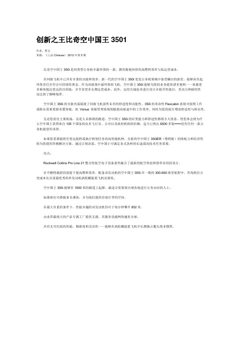
创新之王比奇空中国王3501作者:暂无来源:《上品Choices》 2012年第5期比奇空中国王350i是同类型公务机中最环保的一款,拥有傲视同侪的高燃料效率与低运营成本。
在同级飞机中已具有卓著的功能和效率,新一代的空中国王350i更是公务机领域中备受瞩目的新星,能够肩负起环保责任并符合可持续性理念。
作为该级别中最环保的飞机,空中国王350i能够为您的业务提供诸多便利一一承载更多乘客抵达更远的目的地,并节省更多长期运营成本。
此外,运用尖端技术进行设计并提升性能后,其动力和耐用性也达到了颠峰境界。
空中国王350i的全新内装展现了同级飞机前所未有的舒适度和功能性。
350i的革命性Flexcabin系统可按照工作或娱乐需要重新布置客舱,而Venue客舱管理系统则能提高旅途中的工作效率,同时为您的旅行增添舒适性与娱乐性。
无论您前往主要机场,还是久未修缮的跑道,空中国王350i的应变能力和舒适性都将令人惊喜,使您体会到为什么空中国王获得来自105个国家的众多飞行员、公司以及政府机构的信赖,迄今已售出6500多架——没有任何一款公务机能望其项背。
如果您需要能胜任更远航程或执行特别任务的高性能机种,全新的空中国王350iER(增程版)的续航力和经济性将为您提供终极解决方案。
通过订制改装,空中国王可满足各式各样的长途或高技术任务需要。
亮点:Rockwell Collins Pro Line 21整合性航空电子设备套件融合了最新的航空科技和简单实用的设计。
在不牺牲载荷的前提下提高燃料效率,配备双发动机的空中国王350i在一般的300-600海里航程中,其每机位公里成本比目前最优秀的单发动机涡轮螺旋桨飞机还要低。
空中国王350i能够在1000米的跑道上起降,最适合需要到全球各地进行公务访问的人士。
标准座位可搭载9名乘客,并为他们提供存放行李的空间。
在最大负重的条件下,性能卓越的双发动机仍可于每分钟攀升832米。
由业界最庞大的产品专属工厂提供支援,其服务设施网络遍布全球。
352航空气象飞机颠簸资料

由空气热力原因形成的乱流称 热力乱流。常常出现在对流层 的低层,当有较强的热力对流 发展时,也可能扩展到高空
1.热力乱流
热力颠簸
2.动力乱流 空气流过粗糙不平的地表面或障碍物时出现的乱流,称动力乱流。其影响范围多在 1~2千米高度以下。
什么叫飞机乱流?它的尺度是多大?
2.
影响飞机颠簸强度的因子有哪些?
3.
我国青藏高原为什么多颠簸?
谢谢!
(二)地区性颠簸 1.地表热力性质不同的地区
2.山 区 及 地 表 粗 糙 区
这些地方动力乱流比较强。 这种动力乱流的强度和规模 决定于风向风速、下垫面粗 糙度和近地层大气稳定度三 个因素。
3.积 状 云 区
图7-19 积雨云区 颠簸的水平分布
积状云与飞行
五、颠簸对飞行的影响和处置
(一)颠簸对飞行的影响
2.
根据飞机在垂直方向承受的负荷变
3.
量划分
弱颠簸
颠簸强度符号
中度颠簸
强颠簸
轻度 颠簸 飞机轻微地和有间歇地上下投掷,空速表示度时有改变
中度 颠簸 飞机抖动、频繁地上下投掷,左右摇晃,颠簸,操纵费力,空速指针跳动达10 km/h
严重 颠簸 飞机强烈地抖动,频繁地和剧烈地上下投掷不止,空速指针跳动达15~20 km/h,操纵有困难
根据飞机在垂直方向承受的负荷变量划分
飞机的负荷因素(N)与飞机升力(Y)和重力(G)的关系式N=Y/G △N=△Y/G △Y=M·△a △N=△a/g
│△N│<0.2为弱颠簸;│△N│>0.5为强颠簸;0.2≤│△N│≤0.5为中度颠簸。
F系列战机
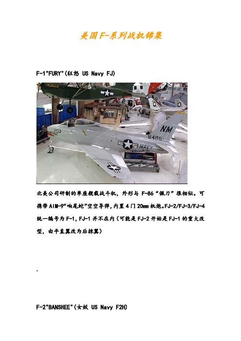
美国F-系列战机锦集F-1"FURY"(狂怒US Navy FJ)北美公司研制的单座舰载战斗机,外形与F-86“佩刀”很相似。
可携带AIM-9“响尾蛇”空空导弹,内置4门20mm机炮。
FJ-2/FJ-3/FJ-4统一编号为F-1,FJ-1并不在内(可能是FJ-2开始是FJ-1的重大改型,由平直翼改为后掠翼).F-2"BANSHEE"(女妖US Navy F2H)麦克唐纳公司研制的单座舰载战斗/侦察机,由FH-1“鬼怪”改进而成。
“女妖”这个绰号的来源很有意思:F-2高速飞行时两具蜗轮引擎会发出凄疠的尖叫声。
机鼻装备了雷达,还有自动驾驶仪、增压座舱、弹射座椅等新式装备。
F-2是韩战的主力舰载轰炸机。
F-3"DEMON"(魔鬼US Navy F3H)麦克唐纳公司研制的第一种后掠翼喷气式战斗机,也是第一种只带导弹不用机炮的战机。
单发、近音速全天侯战斗机,共生产了522架。
.F-4"PHANTOM II"(鬼怪II)麦克唐纳与道格拉斯公司合并后研制的双发双座重型战斗机,是一个庞大的“鬼怪”家族,也是第一种海空军的通用战斗机。
派生型繁杂。
F-4共生产了5000架,至今仍有800架在埃及、德国、希腊、以色列、日本、韩国、西班牙、土耳其服役。
.F-5A/B"Freedom Fighter"自由战士F-5E/F"Tiger II"虎诺斯罗普研制的双发超音速轻型战机,主要供外削,这从F-5A“自由战士”这个绰号就可以看出。
F-5E/F有小部分在美空军服役,主要用途是枫林白露假想敌。
.F-6"SKYRAY"(天光US Navy F4D)道格拉斯公司研制的三角翼战斗机。
装备20mm机炮和响尾蛇空空导弹以截击敌机。
.YF-7A"Sea Dart"(海标枪US Navy YF2Y-1)康维尔公司研制的水上喷气式战斗机。
高压静脉注射造影剂药液外渗的护理策略分析
高压静脉注射造影剂药液外渗的护理策略分析
郑小梅
【期刊名称】《国际医药卫生导报》
【年(卷),期】2012(18)23
【摘要】目的探讨高压静脉注射造影剂药液外渗的护理策略.方法回顾性分析在我院进行CT增强扫描前接受高压静脉造影剂注射的患者1225例.结果有18例发生造影剂药液局部外渗,外渗发生率为1.46%.患者局部肿胀疼痛明显,经硫酸镁湿敷后,16名患者症状消失,两名患者肿胀处出现水泡,经抗感染等处理后痊愈.结论早期预防可防止高压静脉注射造影剂药液外渗现象的发生,紧急救治可用硫酸镁湿敷,严密观察病情,提高自身专业水平,降低外渗的发生率.
【总页数】3页(P3499-3501)
【作者】郑小梅
【作者单位】350001 福州,福建省立医院放射科
【正文语种】中文
【相关文献】
1.高压静脉注射造影剂药液外渗与注射部位相关性研究 [J], 王超琴;刘延锦;李素兰
2.高压注射器静脉注射造影剂渗漏性损伤原因分析及护理 [J], 郭敏;庄薇;刘小倩
3.注射流程再造在预防高压静脉注射造影剂渗漏中的应用 [J], 蔡宇辉;范健容
4.高压注射器静脉注射造影剂渗漏性损伤原因分析及护理 [J], 郭敏;庄薇;刘小倩
5.高压静脉注射造影剂引起药液外渗的护理分析 [J], 徐惠华
因版权原因,仅展示原文概要,查看原文内容请购买。
空客飞机数据

196.2 206.1 166.4 171.5
330.7 361.6 271.2 273.4
378.5 308.6
370.4 375.9 308.6 315.5
507 513.7 396.8 401.2
500.4 513.7 401 412
507.1 513.7 407.9 412.3
540.1 402.3
英制另表为公制空中客车飞机系列单通道系列飞机a318a31912481161564ld345w2008年1月双发宽体飞机a350xwb宽体飞机四发宽体飞机英制双层飞机a340600359543054754243a320150121381807ld345wa3211851616922010ld345wa310300220202002801415a300600266262403612223a300600f10591202nana2223a33020025312362053802627a330200f141152nana2627a33030029512422414403233a350800270164421044026a350900314185024644036a3501000350246226449544a34020026112362133801819a340300300362644403233a340500282542283753031a38080052585338运力典型布局载客货量吨头等舱公务舱经济舱布局最大载客量ld3货运集装箱数量航程典型载客货布局公里nauticalmiles1078991323200海里5950公里3700海里6850公里3000海里5550公里3000海里5550公里43505200405019502650675040005650830081008000670069007200740086709000775079008200动力发动机数量发动机型号2pw6000acfm565b21600238002cfm565bv2500a522000270002cfm565bv2500a522000270002cfm565bv2500a527000330002cf680c2pw400052000590002cf680c2pw40005600061500发动机推力千牛飞机规范机身横截面直径米总长度米翼展米总高度米机翼面积平方米机翼后掠角度标准巡航速度马赫数最大操纵速度马赫数最大巡航高度千米重量及油耗标准及最高选装最大起飞重量吨最大降落重量吨2cf680e1pw4000trent700560006150068000720002cf680c2pw40002pw4000trent7003033202cf680e1pw4000trent70068000720002trentxwb2trentxwb2trent
Outlook Express的设置方
Outlook Express的设置方法Outlook Express是Microsoft(微软)自带的一种电子邮件,简称为OE,是微软公司出品的一款电子邮件客户端,也是一个基于NNTP协议的Usenet客户端。
微软将这个软件与操作系统以及Internet Explorer网页浏览器捆绑在一起。
同时,对于苹果公司“经典”版的麦金塔电脑提供该软件的免费下载(微软不对新版本的Mac OS X操作系统提供该软件,在OS X上微软对应的软件是Microsoft Entourage,Microsoft Entourage是专有商用软件Microsoft Office套装的一部分)。
Office软件内的Outlook与Outlook Express是两个完全不同的软件平台,他们之间没有共享代码,但是这两个软件是设计理念是共通的。
他们之间如此相似的名字使得很多人以为Outlook Express是Outlook软件的“精简版”。
不过Outlook Express并不像Outlook 那样可以和Microsoft Exchange Server相互搭配而有群组软件的功能。
Outlook Express 目前实际上一直是Internet Explorer的一部分,将来似乎也不太可能存在剥离版的OE。
微软承诺“将来的安全扩展”的结果将会是发布新版本的Internet Explorer(当然就包括了OE)。
这个新版的IE/OE将运行在新的“安全”操作平台-Windows Longhorn上。
Outlook Express 设置:(以中文版Outlook Express 6为例)一、首先设置邮件帐号:打开Outlook Express后,单击菜单栏中的“工具”,然后选择“帐号”;二、点击“邮件”标签,点击右侧的“添加”按钮,在弹出的菜单中选择“邮件”;三、在弹出的对话框中,根据提示,输入您的“显示名”,然后点击“下一步”;四、输入您已经申请过的电子邮件地址,如:***@ ,然后点击“下一步”;五、邮件接收服务器您可以选择POP3或IMAP服务器;如果您选择POP3服务器:请输入您邮箱的的POP3和SMTP服务器地址后,再点击“下一步”;POP3服务器: SMTP服务器: (端口号使用默认值)如果您选择IMPA服务器:请输入您邮箱的的IMAP和SMTP服务器地址后,再点击“下一步”;IMAP服务器: SMTP服务器: (端口号使用默认值)POP3(Post Office Protocol 3)即邮局协议的第3个版本,它是规定个人计算机如何连接到互联网上的邮件服务器进行收发邮件的协议。
- 1、下载文档前请自行甄别文档内容的完整性,平台不提供额外的编辑、内容补充、找答案等附加服务。
- 2、"仅部分预览"的文档,不可在线预览部分如存在完整性等问题,可反馈申请退款(可完整预览的文档不适用该条件!)。
- 3、如文档侵犯您的权益,请联系客服反馈,我们会尽快为您处理(人工客服工作时间:9:00-18:30)。
For other values & Custom Designs, contact factory.
Specifications subject to change without notice.
15801 Chemical Lane, Huntington Beach, CA 92649-1595
Tel: (714) 898-0960 • Fax: (714) 896-0971
Rhombus
Industries Inc.
TAXFILT2 - 10/98
20
Attenuates 12 or 16 kHz signals to telco equipment by more than 25 e two F-3501 inductors, one in a parallel LC configuration followed by one in a series configuration, to provide more than 40 dB attenuation of tax pulse signals.
Electrical Specifications at 25O C Inductance D.C. Resistance
D.C. Current
Dielectric P/N F-3501+5%Max.Max.Min.Attenuates Section (Pins)
(mH)
(Ω)
(mA)
(VAC)
12kHz or 16 kHz
L1 (1-2) 1.44 2.30901250 16 kHz, Parallel L1 with C=68 nF L2 (1-6) 2.58 3.25701250 12 kHz, Parallel L2 with C=68 nF L3 (1-5) 4.52 6.3590125016 kHz, Series L3 with C=22 nF L4 (1-4)
7.96
10.7
70
1250
12 kHz, Series L4 with C=22 nF
12 or 16 kHz Tax Pulse Filter
P/N F-3501Thru-hole Package
.394(10.00)MAX.
.375(9.53)MAX.
.110(2.79)MIN.
.080(2.03)
.039
(0.99)
.098(2.49)
.024(0.61)
.465(11.81)MAX.
Bottom View
123
654
Schematic Diagram for P/N F-3501
12654
L1
L4
L3
L2 1. Tested at 10KHz and 100 mV RMS
}
Optional use as Dual
.370(9.40) MAX.
.098(2.50)
.028(0.70)
.375(9.53) MAX.
.34(8.6)
.505 (12.83).490 (12.45)
.375(9.53) MAX.
.025(0.64)
Surface Mount
version Available on Tape & Reel
P/N F-3501G
Surface Mount Package
Suggested Pad Layout
.075 (1.905)TYP.
.100 (2.54)TYP..525(13.34)
.050 (1.27)TYP.
1
23
4
56
For other values & Custom Designs, contact factory.
Specifications subject to change without notice.
15801 Chemical Lane, Huntington Beach, CA 92649-1595
Tel: (714) 898-0960 • Fax: (714) 896-0971
Rhombus
Industries Inc.
TAXFILT2 - 10/98
12 or 16 kHz Tax Pulse Filter
21
P/N F-3504G
EFD-15 Surface Mount
Package
.147(3.75)TYP.
.120(3.05)MIN.
.307(7.80)Pin Diameter is 0.024 (0.6)
.540(13.75)
.590(15.19).590(15.19)
1
Bottom View
2
3
4
8765
}
Optional use as Dual
P/N F-3504GCP EFD-15 Surface Mount with Pick-&-Place Cap
.335(8.50)MAX.
.685(17.4)MAX.
.098(2.5)
.028(0.7)
.016(0.4)
.850 (21.6)
1
5
10
6
.709 (18.0).700(17.8)MAX.
.330(8.38)MAX.
.620(15.75)MAX.
.098(2.5)
.028(0.7)
.016(0.4)
.850 (21.6)
1
5
10
6
.709 (18.0)
.620(15.75)MAX.
Physical Dimensions in Inches (mm)
L1
L4
L3L2136
810Schematic Diagram P/N F-3504
Attenuates 12 or 16 kHz signals to telco equipment by more than 25 e two F-3504 inductors, one in a parallel LC configuration followed by one in a series configuration, to provide more than 40 dB attenuation of tax pulse signals.
87
6
.098 (2.5) TYP..876(22.25)
.045 (1.14) TYP.
.088 (2.24)TYP.
Suggested Pad Layout
12
3
45
910EFD-15 SMD
Electrical Specifications at 25O C Inductance D.C. Resistance
D.C. Current
Dielectric P/N F-3504+5%Max.Max.Min.Attenuates Section (Pins)
(mH)
(Ω)
(mA)
(VAC)
12kHz or 16 kHz
L1 (1-3) 1.44 2.30901250 16 kHz, Parallel L1 with C=68 nF L2 (1-10) 2.58 3.25701250 12 kHz, Parallel L2 with C=68 nF L3 (1-8) 4.52 6.3590125016 kHz, Series L3 with C=22 nF L4 (1-6)
7.96
10.7
70
1250
12 kHz, Series L4 with C=22 nF
1. Tested at 10KHz and 100 mV RMS
P/N F-3504
EFD-15 Thru-hole Package。
