Jlink转接板中文说明文档最新2010版
J-Link使用说明
J-Link应用概述功能包括:●USB 2.0 interface●Any ARM7/ARM9/ARM11, Cortex-M3 core supported, including thumb mode ●Serial Wire Debug supported *●Serial Wire Viewer supported *●Automatic core recognition●Maximum JTAG speed 12 MHz●Download speed up to 720 Kbytes/second **●DCC speed up to 800 Kbytes/second **●Seamless integration into the IAR Embedded Workbench® IDE●No power supply required, powered through USB●SWV support since hardware version 6.0●Support for adaptive clocking●All JTAG signals can be monitored, target voltage can be measured●Support for multiple devices●Fully plug and play compatible●Standard 20-pin JTAG connector●Wide target voltage range: 1.2V - 3.3V, 5V tolerant●USB and 20-pin ribbon cable included●Memory viewer (J-Mem) included●TCP/IP server included, which allows using J-Link via TCP/IP networks●RDI interface available, which allows using J-Link with RDI compliant software ●Flash programming software (J-Flash) available●Flash DLL available, which allows using flash functionality in customapplications●Software Developer Kit (SDK) available●Embedded Trace Buffer (ETB) support●Adapter for 5V JTAG targets available●14-pin JTAG adapter available●Optical isolation adapter available●Target power supply: J-Link can supply up to 300 mA to target with overloadprotection●可以多个客户端同时访问一个目标板J-Link包括:●J-Flash ARM:Flash下载;●J-Link Commander:命令行;●J-Link GDB Server:GDB服务器;●J-Link RDI:RDI调试接口;●J-Link TCP-IP Server:TCP-IP远程调试接口;●J-Mem:内存察看器;J-Flash ARM可用于下载Flash1、通过File-New Project新建工程,也可通过File-Open Project打开一个已经配置好的工程。
JLINK说明书

A product of SEGGER Microcontroller GmbH & Co. KG Flasher ARMManual Rev. 18User guide of the stand-aloneJTAG programmer for ARM CoresDocument: UM08007Date: August 6, 20092Flasher ARM (UM08007)© 2004-2009 SEGGER Microcontroller GmbH & Co. KG DisclaimerSpecifications written in this document are believed to be accurate, but are not guar-anteed to be entirely free of error. The information in this manual is subject to change for functional or performance improvements without notice. Please make sure your manual is the latest edition. While the information herein is assumed to be accurate, SEGGER Microcontroller GmbH & Co. KG (the manufacturer) assumes no responsibility for any errors or omissions. The manufacturer makes and you receive no warranties or conditions, express, implied, statutory or in any communication with you. The manufacturer specifically disclaims any implied warranty of merchantability or fitness for a particular purpose.Copyright noticeYou may not extract portions of this manual or modify the PDF file in any way without the prior written permission of the manufacturer. The software described in this doc-ument is furnished under a license and may only be used or copied in accordance with the terms of such a license.© 2008 SEGGER Microcontroller GmbH & Co. KG, Hilden / GermanyTrademarksNames mentioned in this manual may be trademarks of their respective companies.Brand and product names are trademarks or registered trademarks of their respec-tive holders.Contact addressSEGGER Microcontroller GmbH & Co. KGIn den Weiden 11D-40721 HildenGermanyTel.+49 2103-2878-0Fax.+49 2103-2878-28Email: support@ Internet: RevisionsThis manual describes the Flasher ARM device.For further information on topics or routines not yet specified, please contact us.Revision Date By Explanation18090727AG Chapter "Working with Flasher ARM" * Section "Supported microcontrollers" updated. * Section "JTAG speed" removed. * Section "target interfaces" added.Chapter "Remote control" * Section "Overview" updated.Chapter "Performance" * Section "Performance of MCUs with internal flash memory" updated.17090616AG Chapter "Working with Flasher ARM" * Section "Multiple file support" added.16090519AG Chapter "Remote control" * Section "ASCII command interface" spelling corrections.15090515AGChapter "Remote control" * Section "ASCII command interface" updated.314090508AG Chapter "Remote control"* Section "ASCII command interface" updated.13090506AG Chapter "Remote control"* Section "ASCII command interface" updated.12090122AG Chapter "Working with Flasher ARM"* Section "Supported microcontrollers" updated.11090114AG Chapter "Working with Flasher ARM"* Section "LED status indicators" upadted. 10081211KN Several corrections.9081113AG Chapter "Working with Flasher ARM"* Section "Supported microcontrollers" updated.8081105AG Chapter "Remote control"*Section "ASCII command interface" updated.7081031AG Chapter "Remote control"* Section "Handshake control" updated.* Section "ASCII command interface" updated.6081030AG Chapter "Working with Flasher ARM"* Section "Supported microcontrollers" corrected. Chapter "Remote control"* Section "ASCII command interface" updated.5080929AG Chapter "Working with Flasher ARM"* Section "Supported microcontrollers" updated. Chapter "Working with Flasher ARM"* Section "MSD mode" updated.Chapter "Support and FAQs"* Section "Contacting support" updated. Chapter "Remote control"* Section "ASCII command interface" updated.4080926AG Chapter "Working with Flasher ARM"* Section "Supported microcontrollers" updated.3080912AG Chapter "Remote control" added.Chapter "Background information"* Section "Flasher ARM firmware" removed.2080827AG Several corrections.1080820AG Several improvements/corrections.0071204AG Initial version.Revision Date By ExplanationFlasher ARM (UM08007) © 2004-2009 SEGGER Microcontroller GmbH & Co. KG4Flasher ARM (UM08007)© 2004-2009 SEGGER Microcontroller GmbH & Co. KG5 About this documentThis document describes the Flasher ARM. It provides an overview over the major features of the Flasher ARM, gives you some background information about JTAG, ARM general and describes Flasher ARM related software packages available from Segger. Finally, the chapter Support and FAQs on page51 helps to troubleshoot com-mon problems.Typographic conventionsThis manual uses the following typographic conventions:Style Used forBody Body text.Keyword Text that you enter at the command-prompt or that appears on the display (that is system functions, file- or pathnames).Reference Reference to chapters, tables and figures or other documents.GUIElement Buttons, dialog boxes, menu names, menu commands.Table 1.1: Typographic conventionsFlasher ARM (UM08007)©2004-2009 SEGGER Microcontroller GmbH & Co. KG6Flasher ARM (UM08007)© 2004-2009 SEGGER Microcontroller GmbH & Co. KGEMBEDDED SOFTWARE (Middleware)emWinGraphics software and GUIemWin is designed to provide an effi-cient, processor- and display control-ler-independent graphical userinterface (GUI) for any application thatoperates with a graphical display.Starterkits, eval- and trial-versions areavailable.embOSReal Time Operating SystemembOS is an RTOS designed to offerthe benefits of a complete multitaskingsystem for hard real time applicationswith minimal resources. The profilingPC tool embOSView is included. emFileFile systememFile is an embedded file system withFAT12, FAT16 and FAT32 support.emFile has been optimized for mini-mum memory consumption in RAM andROM while maintaining high speed.Various Device drivers, e.g. for NANDand NOR flashes, SD/MMC and Com-pactFlash cards, are available.emUSBUSB device stackA USB stack designed to work on anyembedded system with a USB clientcontroller. Bulk communication andmost standard device classes are sup-ported.SEGGER TOOLSFlasher Flash programmer Flash Programming tool primarily for microcon-trollers.J-Link JTAG emulator for ARM cores USB driven JTAG interface for ARM cores.J-Trace JTAG emulator with trace USB driven JTAG interface for ARM cores with Trace memory. supporting the ARM ETM (Embed-ded Trace Macrocell).J-Link / J-Trace Related Software Add-on software to be used with SEGGER’s indus-try standard JTAG emulator, this includes flashprogramming software and flash breakpoints.SEGGER Microcontroller GmbH & Co. KG developsand distributes software development tools and ANSIC software components (middleware) for embeddedsystems in several industries such as telecom, medi-cal technology, consumer electronics, automotiveindustry and industrial automation.SEGGER’s intention is to cut software development-time for embedded applications by offering compact flexible and easy to use middleware,allowing developers to concentrate on their application.Our most popular products are emWin, a universal graphic software package for embed-ded applications, and embOS, a small yet efficient real-time kernel. emWin, writtenentirely in ANSI C, can easily be used on any CPU and most any display. It is comple-mented by the available PC tools: Bitmap Converter, Font Converter, Simulator andViewer. embOS supports most 8/16/32-bit CPUs. Its small memory footprint makes itsuitable for single-chip applications.Apart from its main focus on software tools, SEGGER develops and produces programmingtools for flash microcontrollers, as well as J-Link, a JTAG emulator to assist in develop-ment, debugging and production, which has rapidly become the industry standard fordebug access to ARM cores.Corporate Office: United States Office:7Table of Contents1 Introduction (9)1.1Flasher ARM overview (10)1.1.1Features of Flasher ARM (10)1.1.2Working environment (10)1.2Specifications (11)1.2.1Specifications for Flasher ARM (11)1.2.2Flasher ARM Download speed (11)2 Working with Flasher ARM (13)2.1Operating modes (14)2.1.1J-Link mode (14)2.1.2Stand-alone mode (17)2.1.3MSD mode (18)2.2Multiple File Support (19)2.3Target interfaces (20)2.4Supported microcontrollers (21)2.5Support of external flashes (27)2.6Supported ARM Cores (28)3 Remote control (29)3.1Overview (30)3.2Handshake control (31)3.3ASCII command interface (32)3.3.1Introduction (32)3.3.2General command and reply message format (32)3.3.3Communication port settings (32)3.3.4Commands to Flasher (32)3.3.5Reply from Flasher ARM (36)4 Performance (39)4.1Performance of MCUs with internal flash memory (40)5 Hardware (41)5.1JTAG Connector (42)5.1.1Pinout (42)5.1.2Target board design for JTAG (43)5.1.3Target power supply (43)5.2Using the JTAG connector with SWD (44)5.2.1Pin Out (44)5.3RESET, nTRST (45)5.4Adapters (46)5.4.1J-Link JTAG Isolator (46)5.4.2Pinout (46)5.5How to determine the hardware version (47)6 Background information (49)6.1Flash programming (50)6.1.1How does flash programming via Flasher ARM work ? (50)6.1.2Data download to RAM (50)Flasher ARM (UM08007)© 2004-2009 SEGGER Microcontroller GmbH & Co. KG8Flasher ARM (UM08007)© 2004-2009 SEGGER Microcontroller GmbH & Co. KG6.1.3Available options for flash programming (50)7 Support and FAQs (51)7.1Contacting support..................................................................................527.2Frequently Asked Questions. (53)8 Glossary (55)9 Literature and references (59)9 Chapter 1IntroductionThis chapter gives a short overview about the Flasher ARM.Flasher ARM (UM08007)©2004-2009 SEGGER Microcontroller GmbH & Co. KG10CHAPTER 1IntroductionFlasher ARM (UM08007)© 2004-2009 SEGGER Microcontroller GmbH & Co. KG 1.1Flasher ARM overviewFlasher ARM is a programming tool for microcontrollers with on-chip or external Flash memory and ARM core. Flasher ARM is designed for programming flash targets with the J-Flash software or stand-alone. In addition to that Flasher ARM has all of the J-Link functionality. For more information about J-Link please refer to the J-Link / J-Trace User Guide which can be downloaded at .Flasher ARM connects via USB or via RS232 interface to a PC, running Microsoft Win-dows 2000, Windows XP, Windows 2003 or Windows Vista. Flasher ARM has a built-in 20-pin JTAG connector, which is compatible with the standard 20-pin connector defined by ARM.1.1.1Features of Flasher ARM •Three boot modes: J-Link mode, stand-alone mode, MSD mode •Stand-alone JTAG programmer (Once set up, Flasher can be controlled without the use of PC program)•No power supply required, powered through USB •Support for ARM7/ARM9/Cortex-M3•Supports internal and external flash devices •64 MB memory for storage of target program •Can be used as J-Link (JTAG emulator) with a download speed of up to 720Kbytes/second •Programming speed between 30-300 Kbytes/second depending on target hard-ware •Serial in target programming supported •Data files can updated via J-Flash •Target interface: JTAG/SWD1.1.2Working environmentGeneralFlasher ARM can be operated from a PC with an appropriate software like J-Flash or in stand-alone mode.Host SystemIBM PC/AT or compatible. CPU: 486 (or better) with at least 182MB of RAM, running Microsoft Windows 2000, Windows XP, Windows 2003 or Windows Vista. It needs to have an USB or RS232 interface available for communication with Flasher ARM.Power supplyFlasher requires 5V DC, min. 100mA via USB connector. If USB is not connected, the USB connector is used to power the device. Supply voltage is the same in this case.Please avoid excess voltage.Installing Flasher ARM PC-software J-FlashThe latest version of the J-Flash software, which is part of the J-Link software and documentation package, can be downloaded from our website: . For more information about using J-Flash please refer to the J-Flash User Guide which is also available for download on our website.111.2Specifications1.2.1Specifications for Flasher ARM1.2.2Flasher ARM Download speedThe following table lists Flasher ARM performance values (Kbytes/second) for writing to memory (RAM) via the JTAG interface:Note:The actual speed depends on various factors, such as JTAG, clock speed,host CPU core etc.Power SupplyUSB powered, 100mA for Flasher ARM. 500mA if target is powered by Flasher ARMUSB Host Interface USB 2.0, full speed RS232 Host Interface RS232 9-pinTarget InterfaceJTAG 20-pin (14-pin adapter available)Max. JTAG Transfer Rate up to 12 MHz Supported Target Voltage 1.8 - 5V Target supply voltage 5VTarget supply current Max. 400mA Operating Temperature +5°C ... +60°C Storage Temperature-20°C ... +65 °C Relative Humidity (non-condensing)<90% rHSize (without cables)121mm x 66mm x 30mm Weight (without cables)120gSupported OSMicrosoft Windows 2000Microsoft Windows XPMicrosoft Windows XP x64Microsoft Windows 2003Microsoft Windows 2003 x64Microsoft Windows VistaMicrosoft Windows Vista x64Hardware ARM7Memory download Flasher ARM Rev. 1720 Kbytes/s (12MHz JTAG)12CHAPTER 1Introduction13 Chapter 2Working with Flasher ARMThis chapter describes functionality and how to use Flasher ARM.14CHAPTER 2Working with Flasher ARM2.1Operating modesFlasher ARM is able to boot in 3 different modes:•J-Linkmode•Stand-alone mode•MSD (Mass storage device) modeIf Flasher ARM can enumerate on the USB port, Flasher ARM boots in "J-Link mode".In this mode Flasher ARM can be used as a J-Link. When supply power is enabled and Flasher ARM cannot enumerate, the "stand-alone mode" is started. In this mode Flasher ARM can be used as a stand-alone flash programmer. When the Start/Stop button is kept pressed when power supply is enabled, Flasher ARM boots in "MSD mode". In this mode Flasher ARM boots as a mass storage device.2.1.1J-Link modeWhen you want to use Flasher ARM for the first time you need to install the J-Link ARM related software and documentation pack. After installation, connect Flasher ARM to the host PC via USB. For more information about how to install the J-Link ARM related software and documentation pack please refer to the J-Link / J-Trace User Guide , chapter Setup which can be downloaded from /download_jlink.html.2.1.1.1Connecting the target systemPower-on sequenceIn general, Flasher ARM should be powered on before connecting it with the target device. That means you should first connect Flasher ARM with the host system via USB / RS232 and then connect Flasher ARM with the target device via JTAG. Power-on the device after you connected Flasher ARM to it. Flasher ARM will boot in "J-Link mode".Verifying target device connection with J-Link.exeIf the USB driver is working properly and your Flasher ARM is connected with the host system, you may connect Flasher ARM to your target hardware. Then start the J-Link command line tool JLink.exe , which should now display the normal Flasher ARM related information and in addition to that it should report that it found a JTAG target and the target’s core ID. The screenshot below shows the output of JLink.exe .2.1.1.2Setting up Flasher ARM for stand-alone modeIn order to set up Flasher ARM for the "stand-alone mode" it has to be in "J-Link mode". When the correct connection of Flasher ARM to the host PC is verified start the J-Flash software. For more information about J-Flash, please refer to theJ-Flash15 User Guide. The J-Link related software and documentation package contains the J-Flash software. When J-Flash is started, open an appropriate J-Flash project file and an appropriate data file for the target you want to program with Flasher ARM.16CHAPTER 2Working with Flasher ARM Now, choose File->Download to emulator from the menu in order to download the target configuration as well as the data file to the Flasher ARM.17 After the download, you should see in the J-Flash Log window that the Flasher.cfg and the Flasher.dat files have been successfully downloaded.From now on, Flasher ARM can be used in "stand-alone mode" for stand-alone pro-gramming.2.1.2Stand-alone modeIn order to use Flasher ARM in "stand-alone mode", it has to be configured first, as described in Setting up Flasher ARM for stand-alone mode on page14. To boot Flasher ARM in the "stand-alone mode", only the power supply to Flasher ARM has to be enabled (Flasher ARM should not be connected to a PC). In the "stand-alone mode" Flasher ARM can be used as a stand-alone flash programmer.Note:Flasher ARM can only program the target device it was configured for. In order to program another target device, you have to repeat the steps described in Setting up Flasher ARM for stand-alone mode on page14.2.1.2.1LED status indicatorsProgress and result of an operation is indicated by Flasher ARM’s LEDs:Status of LED MeaningGREEN, high frequency flashing (10 kHz)Enumerating Flasher ARM. This only hap-pens before the first programming opera-tion is performed.GREEN, after programming operation has been started Connect to target and perform init sequence.18CHAPTER 2Working with Flasher ARM2.1.3MSD modeWhen pressing the Start/Stop button of Flasher ARM while connecting it to the PC,Flasher ARM will boot in the "MSD mode". This mode can be used to downdate a Flasher ARM firmware version if a firmware update did not work properly and it can be used to configure Flasher ARM for the "stand-alone mode", without using J-Flash.If Flasher ARM has been configured for "stand-alone mode" before, there will be four files on the MSD, FLASHER.CFG , FLASHER.DAT , FLASHER.LOG , SERIAL.TXT .FLASHER.CFG contains the configuration settings for programming the target device and FLASHER.DAT contains the data to be programmed. FLASHER.LOG contains all log-ging information about the commands, performed in stand-alone mode. The SERIAL.TXT contains the serial number, which will be programmed next. Currently, J-Flash does not support to configure Flasher ARM for automated serial number pro-gramming.If you want to configure multiple Flasher ARM for the same target you do not have to use J-Flash all the time. It is also possible to copy the FLASHER.CFG and the FLASHER.DAT files from a configured Flasher ARM to another one. To copy these files boot Flasher ARM in "MSD mode".GREEN, slow blinking (1 kHz)Erasing/Programming/Verifying opera-tion is in progress.GREEN Operation successful / Ready.REDOperation failed.Status of LEDMeaning192.2Multiple File SupportIt is also possible to have multiple data files and config files on Flasher ARM, to make Flasher ARM more easy to use in production environment. To choose the correct con-figuration file and data file pair, a FLASHER.INI file is used. This init file contains a [FILES] section which describes which configuration file and which data file should be used for programming. A sample content of a FLASHER.INI file is shown below: [FILES]DataFile = "Flasher1.dat"ConfigFile = "Flasher1.cfg"Using this method all configuration files and data files which are used in the produc-tion only have to be downloaded once. From there on a configuration file / data file pair can be switched by simply replacing the FLASHER.INI by a new one, which con-tains the new descriptions for the configuration file and data file. The FLASHER.INI can be replaced in two ways:1.Boot Flasher ARM in MSD mode in order to replace the FLASHER.INI2.If Flasher ARM is already integrated into the production line, runs in stand-alonemode and can not be booted in other mode: Use the file I/O commands providedby the ASCII interface of Flasher ARM, to replace the FLASHER.INI. For moreinformation about the file I/O commands, please refer to File I/O commands onpage34.20CHAPTER 2Working with Flasher ARM2.3Target interfacesSince Flasher ARM is compatible to J-Link it also supports the same target interfaces.Currently the following target interfaces are supported:•JTAG•SWDFor more information about the target interfaces itself and the maximum speeds that can be used for each target interface, please refer to UM08001, chapter "Working with J-Link and J-Trace", section "JTAG interface" and UM08001, chapter "Working with J-Link and J-Trace", section "SWD interface".Note:Flasher ARM currently does not support SWO.212.4Supported microcontrollersThe following table lists all the devices which are currently supported by Flasher ARM.Manufacturer DevicesAnalog Devices ADuC7020x62Analog Devices ADuC7021x32Analog Devices ADuC7021x62Analog Devices ADuC7022x32Analog Devices ADuC7022x62Analog Devices ADuC7024x62Analog Devices ADuC7025x32Analog Devices ADuC7025x62Analog Devices ADuC7026x62Analog Devices ADuC7027x62Analog Devices ADuC7028x62Analog Devices ADuC7030Analog Devices ADuC7031Analog Devices ADuC7032Analog Devices ADuC7033Analog Devices ADuC7060Analog Devices ADuC7128Analog Devices ADuC7129Analog Devices ADuC7229x126Atmel AT91FR40162Atmel AT91SAM7A3Atmel AT91SAM7S32Atmel AT91SAM7S321Atmel AT91SAM7S64Atmel AT91SAM7S128Atmel AT91SAM7S256Atmel AT91SAM7S512Atmel AT91SAM7SE32Atmel AT91SAM7SE256Atmel AT91SAM7SE512Atmel AT91SAM7X128Atmel AT91SAM7X256Atmel AT91SAM7X512Atmel AT91SAM7XC128Atmel AT91SAM7XC256Atmel AT91SAM7XC512Freescale MAC7101Freescale MAC7106Freescale MAC7111Freescale MAC7112Freescale MAC7116Freescale MAC7121Freescale MAC7122Freescale MAC7126Freescale MAC7131Freescale MAC7136Table 2.2: Supported microcontrollers22CHAPTER 2Working with Flasher ARMManufacturer DevicesFreescale MAC7141Freescale MAC7142Luminary LM3S101Luminary LM3S102Luminary LM3S301Luminary LM3S310Luminary LM3S315Luminary LM3S316Luminary LM3S317Luminary LM3S328Luminary LM3S601Luminary LM3S610Luminary LM3S611Luminary LM3S612Luminary LM3S613Luminary LM3S615Luminary LM3S617Luminary LM3S618Luminary LM3S628Luminary LM3S801Luminary LM3S811Luminary LM3S812Luminary LM3S815Luminary LM3S817Luminary LM3S818Luminary LM3S828Luminary LM3S2110Luminary LM3S2139Luminary LM3S2410Luminary LM3S2412Luminary LM3S2432Luminary LM3S2533Luminary LM3S2620Luminary LM3S2637Luminary LM3S2651Luminary LM3S2730Luminary LM3S2739Luminary LM3S2939Luminary LM3S2948Luminary LM3S2950Luminary LM3S2965Luminary LM3S6100Luminary LM3S6110Luminary LM3S6420Luminary LM3S6422Luminary LM3S6432Luminary LM3S6610Luminary LM3S6633Luminary LM3S6637Luminary LM3S673023Manufacturer DevicesLuminary LM3S6918Luminary LM3S6938Luminary LM3S6952Luminary LM3S6965NXP LPC1111NXP LPC1113NXP LPC1311NXP LPC1313NXP LPC1342NXP LPC1343NXP LPC1751NXP LPC1752NXP LPC1754NXP LPC1756NXP LPC1758NXP LPC1764NXP LPC1765NXP LPC1766NXP LPC1768NXP LPC2101NXP LPC2102NXP LPC2103NXP LPC2104NXP LPC2105NXP LPC2106NXP LPC2109NXP LPC2114NXP LPC2119NXP LPC2124NXP LPC2129NXP LPC2131NXP LPC2132NXP LPC2134NXP LPC2136NXP LPC2138NXP LPC2141NXP LPC2142NXP LPC2144NXP LPC2146NXP LPC2148NXP LPC2194NXP LPC2212NXP LPC2214NXP LPC2292NXP LPC2294NXP LPC2364NXP LPC2366NXP LPC2368NXP LPC2378NXP LPC238724CHAPTER 2Working with Flasher ARMManufacturer DevicesNXP LPC2388NXP LPC2468NXP LPC2478NXP LPC2917NXP LPC2919NXP LPC2927NXP LPC2929ST STM32F101C6ST STM32F101C8ST STM32F101CBST STM32F101R6ST STM32F101R8ST STM32F101RBST STM32F101RCST STM32F101RDST STM32F101REST STM32F101T6ST STM32F101T8ST STM32F101V8ST STM32F101VBST STM32F101VCST STM32F101VDST STM32F101VEST STM32F101ZCST STM32F101ZDST STM32F101ZEST STM32F102C6ST STM32F102C8ST STM32F102CBST STM32F103C6ST STM32F103C8ST STM32F103R6ST STM32F103R8ST STM32F103RBST STM32F103RCST STM32F103RDST STM32F103REST STM32F103T6ST STM32F103T8ST STM32F103V8ST STM32F103VBST STM32F103VCST STM32F103VDST STM32F103VEST STM32F103ZCST STM32F103ZDST STM32F103ZEST STR710FZ1ST STR710FZ2ST STR711FR025Manufacturer DevicesST STR711FR1ST STR711FR2ST STR712FR0ST STR712FR1ST STR712FR2ST STR715FR0ST STR730FZ1ST STR730FZ2ST STR731FV0ST STR731FV1ST STR731FV2ST STR735FZ1ST STR735FZ2ST STR736FV0ST STR736FV1ST STR736FV2ST STR750FV0ST STR750FV1ST STR750FV2ST STR751FR0ST STR751FR1ST STR751FR2ST STR752FR0ST STR752FR1ST STR752FR2ST STR755FR0ST STR755FR1ST STR755FR2ST STR755FV0ST STR755FV1ST STR755FV2ST STR910FAM32ST STR910FAW32ST STR910FAZ32ST STR911FAM42ST STR911FAM44ST STR911FAM46ST STR911FAM47ST STR911FAW42ST STR911FAW44ST STR911FAW46ST STR911FAW47ST STR911FM32ST STR911FM42ST STR911FM44ST STR911FW32ST STR911FW42ST STR911FW44ST STR912FAW32ST STR912FAW4226CHAPTER 2Working with Flasher ARMManufacturer DevicesST STR912FAW44ST STR912FAW46ST STR912FAW47ST STR912FAZ42ST STR912FAZ44ST STR912FAZ46ST STR912FAZ47ST STR912FM32ST STR912FM42ST STR912FM44ST STR912FW32ST STR912FW42ST STR912FW44TI TMS470R1A64TI TMS470R1A128TI TMS470R1A256TI TMS470R1A288TI TMS470R1A384TI TMS470R1B512TI TMS470R1B768TI TMS470R1B1MTI TMS470R1VF288TI TMS470R1VF688TI TMS470R1VF689Toshiba TMPM330272.5Support of external flashesFlasher ARM supports the programming of CFI compliant, external NOR flashes. For a list of all supported flash devices, please refer to the J-Flash User Guide (UM08003), chapter Supported Flash Devices.28CHAPTER 2Working with Flasher ARM2.6Supported ARM CoresFlasher ARM has been tested with the following cores, but should work with any ARM7/9, Cortex-M0/M1/M3 core. If you experience problems with a particular core, do not hesitate to contact Segger.•ARM7TDMI (Rev 1)•ARM7TDMI (Rev 3)•ARM7TDMI-S (Rev 4)•ARM920T•ARM922T•ARM926EJ-S•ARM946E-S•ARM966E-S•Cortex-M0•Cortex-M1•Cortex-M3。
10-JLINK-ARM-OB使用手册
0、JLINK-ARM-OB使用手册
《零死角玩转STM32》系列的配套程序使用的是MDK开发环境,在开发环境中的下载配置是使用JLINK-V8,JLNIK-V8如下图所示,如果购买的仿真器是JLINK-V8的朋友,则不用修改工程的配置,即可根据教程的方法来下载。
如果是购买了JLINK-ARM-OB的朋友,JLINK-ARM-OB采用三线下载,体积更小,速度可达5M,固件不易丢失,比现在市面上的大块头JLINK-V8更稳定,野火在这里强烈推荐大家使用。
购买了JLINK-ARM-OB的朋友,如果使用《零死角玩转STM32》的配套程序的话,则需要重新配置下MDK的下载模式。
具体步骤如下:
1、将JLINK-ARM-OB连接电脑和开发板(接开发板中的SWD接
口)。
在使用JLINK-ARM-OB仿真器之前请先安装JLINK驱动,JLINK驱动在光盘目录下的安装软件文件夹里面。
2、修改MDK的下载配置,改为SWD(即JLINK-ARM-OB)下载模
式,速率可设置为2M,当设置为5M时,速率最快。
Options for Target ->Debug->Settings->Port->SWD
Max Clock-> 2MHZ
注意:当用JLINK-ARM-OB连接上电脑和开发板,且修改MDK的下载设置时,可能会提示升级固件库,此时点击是即可。
JLINK使用教程详解

2021/2/11
7
配置ADS工程
菜单>Edit>DebugRel Settings
1、ARM Assembler
目的:选择与ARM核相匹配的汇编代码编译器
2021/2/11
8
配置ADS工程
菜单>Edit>DebugRel Settings
2、ARM C Compiler
目的:选择与ARM核相匹配的C代码编译器
Main.o .bin/.axf. .hex/.elf
…… ……
CODE32
AREA Init,CODE,READONLY
ENTRY
;指定程序入口地址
12
配置ADS工程
菜单>Edit>DebugRel Settings
配置完毕之后一定要注意存盘(ctrl+s), 这样配置才会生效,否则编译时会报错。
写程序非常方便。
2021/2/11
4
Part 1
JLINK+AXD+S3C4510B调试
仿真
A、配置ADS工程
※
B、编译并进入AXD
C、配置AXD
※
D、调试仿真
2021/2/11
5
配置ADS工程
菜单>Edit>DebugRel Settings
高级语言程序从源代码到成为可在硬件上运行的可执行代码需要经历 四个阶段:
21
配置ADS工程
菜单>Edit>DebugRel Settings
4、 ARM Linker(Output)
目的:设置代码段的起始地址为FLASH的起始地址。
2021/2/11
J-Link用户手册(中文)

J-Link用户指南(本手册适用于V6.0、V7.0、V8.0版本的J-LINK)1.J-Link ARM JTAG 仿真器简介J-Link 是 SEGGER 公司为支持仿真 ARM 内核芯片推出的 JTAG仿真器。
配合 IAR EWARM,ADS,KEIL,WINARM,RealView 等集成开发环境支持所有 ARM7/ARM9 内核芯片的仿真,通过 RDI 接口和各集成开发环境无缝连接,操作方便、连接方便、简单易学,是学习开发 ARM 最好最实用的开发工具。
J-Link ARM 主要特点* IAR EWARM 集成开发环境无缝连接的JTAG 仿真器* 支持所有 ARM7/ARM9 内核的芯片,以及 cortex M3,包括 Thumb 模式* 支持 ADS,IAR,KEIL,WINARM,REALVIEW 等几乎所有的开发环境* 下载速度高达 ARM7:600kB/s,ARM9:550kB/s,通过 DCC 最高可达 800 kB/s* 最高 JTAG 速度 12 MHz* 目标板电压范围 1.2V –3.3V,兼容5V* 自动速度识别功能* 监测所有 JTAG 信号和目标板电压* 完全即插即用* 使用 USB 电源(但不对目标板供电)* 带 USB 连接线和 20 芯扁平电缆* 支持多 JTAG 器件串行连接* 标准 20 芯JTAG 仿真插头* 选配 14 芯 JTAG 仿真插头* 带J-Link TCP/IP server,允许通过 TCP/ IP 网络使用J-LinkJ-Link 支持 ARM 内核* ARM7TDMI(Rev 1)* ARM7TDMI(Rev 3)* ARM7TDMI-S(Rev 4)* ARM720T * ARM920T*ARM926EJ-S*ARM946E-S*ARM966E-S* ARM11* Cortex-M3速度信息RevisionARM7Memory downloadARM9Memory downloadJ-Link Rev. 1-4 150.0 kB/s(4MHz JTAG)75.0 kB/s(4MHz JTAG)J-Link Rev. 5-8720.0 kB/s(12MHz JTAG)550.0 kB/s(12MHz JTAG)J-Trace Rev. 1420.0 kB/s(12MHz JTAG)280.0 kB/s(12MHz JTAG2.J-LINK 驱动安装J-LINK 是本站开发的兼容产品,具有一样的性能,但是却只有十分之一的价格!首先到/download_jlink.html 下载最新的 J-LINK驱动软,J-Link ARM software and documentation pack ,内含USB driver, J-Mem, J-Link.exe and DLL for ARM, J-Flash and J-Link RDI。
jlink的使用方法

jlink的使用方法JLink是Segger公司开发的一款用于嵌入式系统的调试和仿真工具。
它是一种硬件和软件的解决方案,可用于调试和烧录各类微控制器,如ARM和Cortex-M系列。
在本文中,我将详细介绍JLink的使用方法,并提供一些常见问题的解决方案。
一、JLink的配置要使用JLink进行调试和仿真,首先需要进行一些基本的配置。
以下是配置JLink所需的步骤:1.安装JLink软件和驱动程序:在Segger官方网站上下载JLink软件并进行安装。
安装完成后,选择适合您的操作系统的驱动程序进行安装。
2.连接JLink调试器:将JLink调试器连接到电脑的USB接口上。
在连接之前,确保JLink调试器已插入目标设备上的JTAG或SWD接口。
3.配置调试选项:打开JLink软件,并选择目标设备的型号和调试接口类型。
您可以在菜单栏上的“文件”选项中找到这些选项。
4.配置调试连接:选择正确的调试连接选项,如JTAG或SWD。
您还可以选择连接速度和其他调试选项。
5.配置目标设备:选择目标设备的工作电压、频率等参数。
这些参数应与目标设备的规格书相匹配。
通过上述步骤配置JLink之后,您就可以开始使用JLink进行调试和仿真。
二、JLink的调试功能JLink具有强大的调试功能,可以帮助开发人员诊断和解决嵌入式系统中的问题。
以下是一些常见的JLink调试功能:1.断点调试:使用JLink可以设置断点,在程序执行到特定的代码行时暂停执行,以便开发人员检查程序状态和变量值。
2.单步调试:JLink支持单步调试功能,可以逐条执行程序,并在每个代码行上暂停执行,以便开发人员检查程序的执行流程。
3.变量监视:JLink可以监视变量的值,以便开发人员可以实时查看变量的值,并在程序运行时进行调试。
4.内存查看:JLink可以查看目标设备的内存内容,包括程序代码、数据和堆栈信息等。
这对于分析内存泄漏和其他相关问题非常有帮助。
JLINK V8最新用户手册中文版_下册
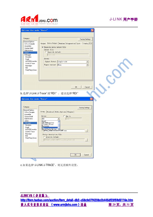
“RDI”b.选择“J-Link/J-Trace”或“RDI” ,建议选择JLINK V8(企业版):d.如果选择“RDI”,则还需要指定J-LINKRDI.DLL 的位置:e.设置完成后将多出一个RDI 菜单,如下图:JLINK V8(企业版):f.在RDI 菜单下有“CONFIGURE”选项,这里可以对JTAG 时钟,FLASH,断点,CPU 等进行设置,请注意里面的FLASH 和CPU 型号与目标板相吻合。
g.另外,IAR 下使用J-LINK 的时候,注意不要再使用IAR 自带的FLASHLOADER 软件进行FLASH 下载:将“Use flash loader”前的勾去掉,使用J-LINK 的FLASH 编程算法和使用IAR 的FLASHLOADER ,速度可能差好几倍!4.4J-FLASH ARM 使用设置安装完J-LINK 的驱动后会出现两个快捷图标,其中一个是J-FLASH ARM,这个应用程序是用来单独编程FLASH 的(需要J-FLASH ARM License 支持)。
JLINK V8(企业版):首次使用的时候应该在File 菜单,选择Open Project ,选择你的目标芯片:JLINK V8(企业版):然后通过“File”菜单下的“Open…”来打开需要烧写的文件,可以是.bin 格式,也可以是.hex 格式,甚至可以是.mot 格式。
注意起始地址。
接下来在“Options”选择“Project settings”:在ARM 选项卡可以选择目标芯片,如果不是具备片内FLASH 的芯片的话请选择“GenericARM7/ARM9”。
JLINK V8(企业版):FLASH 选项卡,如果之前是“Opon project”这里就不需要设置,默认即可,如果是自己新建的project,则需要小心设置。
如果前面的ARM 选项卡里选择的是“Generic ARM7/ARM9”,则可以在FLASH 选项卡里面选择FLASH 型号,JLINK支持非常多的FLASH 器件,只要是大厂的FLASH ,基本都可以找到!而且会不断升级以支持最新器件。
JLink和JTAG接口详细及接线

JLink 和JTAG 接口详细及接线JTAG 各类接口针脚定义、含义一、引脚定义Test Clock Input (TCK)-----强制要求1TCK 在IEEE1149.1 标准里是强制要求的。
TCK 为TAP 的操作提供了一个独立的、基本的时钟信号,TAP 的所有操作都是通过这个时钟信号来驱动的。
Test Mode SelecTIon Input (TMS)-----强制要求2TMS 信号在TCK 的上升沿有效。
TMS 在IEEE1149.1 标准里是强制要求的。
TMS 信号用来控制TAP 状态机的转换。
通过TMS 信号,可以控制TAP 在不同的状态间相互转换。
Test Data Input (TDI)-----强制要求3TDI 在IEEE1149.1 标准里是强制要求的。
TDI 是数据输入的接口。
所有要输入到特定寄存器的数据都是通过TDI 接口一位一位串行输入的(由TCK 驱动)。
Test Data Output (TDO)-----强制要求4TDO 在IEEE1149.1 标准里是强制要求的。
TDO 是数据输出的接口。
所有要从特定的寄存器中输出的数据都是通过TDO 接口一位一位串行输出的(由TCK 驱动)。
Test Reset Input (TRST)----可选项1这个信号接口在IEEE 1149.1 标准里是可选的,并不是强制要求的。
TRST 可以用来对TAPController 进行复位(初始化)。
因为通过TMS 也可以对TAP Controll 进行复位(初始化)。
所以有四线JTAG 与五线JTAG 之分。
(VTREF)-----强制要求5接口信号电平参考电压一般直接连接Vsupply。
这个可以用来确定ARM 的JTAG 接口使用的逻辑电平(比如3.3V 还是5.0V?)Return Test Clock (RTCK)----可选项2可选项,由目标端反馈给仿真器的时钟信号,用来同步TCK 信号的产生,不使用时直接接地。
Transcend JetFlash 中文说明书 (版本 1.0)

JetFlash™ 中文使用手册(版本 1.0)目录产品介绍 (2)包装内容 (2)产品特色 (2)系统需求 (2)安装驱动程序 (3)在Windows 98SE(第二版)下安装驱动程序 (3)在Windows Me、2000 及XP 下安装驱动程序 (3)在Mac OS 9.0或之后的版本下安装驱动程序 (3)在Linux Kernel 2.4.2或之后的版本下安装驱动程序 (3)将JetFlash™ 格式化 (4)如何安全地移除JetFlash™ (5)在Windows 98SE (第二版)下移除JetFlash (5)在Windows Me、2000及XP下移除JetFlash (5)在Mac® OS 9.0, 或更新的版本; 及Linux® Kernel 2.4.2, 或更新的版本下移除JetFlash (5)JetFlash™ 150 系列产品 (6)产品规格 (6)订购信息 (6)JetFlash™ 120系列产品 (7)产品规格 (7)订购信息 (7)JetFlash™ 110系列产品 (8)产品规格 (8)订购信息 (8)JetFlash™ 2A系列产品 (9)产品规格 (9)订购信息 (9)产品介绍感谢您选购创见资讯所生产制造的JetFlash™ 。
本产品能让您更方便且快速地在台式计算机与笔记本计算机间,存取及传输大量数据。
由于本产品提供较传统存储装置更高的容量、及更快的传输速率,其功能可用来存储/备份/传输您的文件、数据夹、文件夹、照片及其它的电子文件。
此外它的超强可移植性及文件保存能力,搭配令人惊艳的流线外观,绝对会带给您截然不同的全新感受。
包装内容JetFlash™系列产品之包装盒内含有下列物品:JetFlash™颈绳应用软件光盘USB延长线(只有JetFlash™ 2A 系列提供)快速安装说明产品特色符合USB2.0 接口规格并兼容于 USB1.1规格。
PJ-PU2010系列项目器操作指南说明书
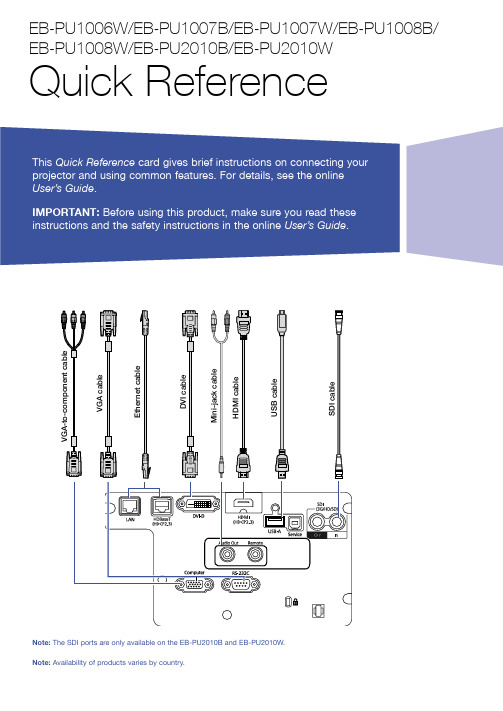
Switching Between Image SourcesPress the Search button or one of the source buttons (remote control), or the Source Search button (projector).Selecting the Lens TypeMake sure the Lens Type setting is correct for the lens you are using.1. P ress the Menu button.2. S elect Extended > Operation >Advanced > Lens Type .N ote: If the Lens Type setting is greyed out, the projector has automatically detected the installed lens and you can skip the remaining steps.3. S elect the lens you are using.4. W hen you’re done, press the Menubutton to exit.Changing Screen TypeSet the Screen Type setting to the screen’s aspect ratio. 1. P ress the Menu button.2. S elect Extended > Display >Screen > Screen Type .3. S elect the screen’s aspect ratio.N ote: The displayed image should matchthe screen’s size and aspect ratio.Turning the Projector On1. T urn on your computer or imagesource.2. R emove the lens cover.3. P ress the On button on theprojector or the remote control. After the status light stays blue, the projector is ready.N ote: If the Direct Power On function is enabled, you can turn the projector on without pressing the On button; just plug it in or flip the switch controlling the outlet to which the projector is connected. To turn on this feature, see the online User’s Guide .4. I f your image does not appear, see“Switching Between Image Sources” or “Troubleshooting.”Changing the Language of the Projector MenusThe default language of the projector’s menu system is English, but you can change it as necessary.1. P ress the Menu button to accessthe projector’s menu system.2. S elect Extended > Language .3. S elect your language.4. W hen you’re done, press the Menubutton to exit.2. P ress the or arrow buttons tomake the adjustment. 3. P ress the Esc button to finish theadjustment.Correcting Image ShapeIf your image is uneven on the sides, you can use the projector’s distortion correction features, such asH/V-Keystone and Quick Corner ®, to adjust the shape. See the online User’s Guide .Making Other Image AdjustmentsFor help on using the projector’sfeatures to improve the image quality, see the online User’s Guide . You can also view information on how to adjust the image color, position, and edges (Edge Blending) when projecting from multiple projectors to create one seamless widescreen image.Turning the Projector OffPress the Standby button to turn the projector off. If you see a confirmation message, press the Standby button again.Note: If the Direct Power On function isenabled, you can unplug the projector or flip the switch controlling the outlet to which the projector is connected instead. To turn on this feature, see the online User’s Guide .With Epson’s Instant Off ® technology, you don’t have to wait for the projector to cool down; just turn it off or unplug it when you’re done.4. W hen you’re done, press the Menubutton to exit.N ote: After changing the screen type, you may need to change the aspect ratio of the projected image depending on the inputsignal. Press the Aspectbutton on the remote control to change the aspect ratio, if necessary.Adjusting Image Position1. P ress the Lens Shift button(remote control) or the Lens button (projector).2. P ress the arrow buttons to adjustthe position of the projected image.3. W hen you’re done, press the Escbutton to finish the adjustment.If the projector is on a table, you can level the image by turning any of the projector’s adjustable feet.Zooming and Focusing1. O n the remote control, press theZoom or Focus button.O n the projector, press the Lensbutton repeatedly until the focus or zoom adjustment screen is shown.TroubleshootingIf you see a blank screen or the message No signal•M ake sure the status light on the projector is blue and not flashing, and the lens cover is removed.•M ake sure the cables are connected correctly. See the online User’s Guide.•Y ou may need to change the image source. See “Switching Between Image Sources.” Also make sure the source device is turned on.If the projector and the notebook don’t display the same image Windows®If you are using a Windows laptop, press the function key on your keyboard that lets you display on an external monitor. It may be labeled CRT/LCD or have an icon such as . You may have to hold down the Fn key while pressing it (such as Fn + F7). Wait a moment for the display to appear.On Windows 7 or later, hold down the Windows key and press P at the same time, then click Duplicate.MacOpen System Preferences and select Displays. Click the Arrangementtab and select the Mirror Displays checkbox.Where to Get Help ManualsFor more information about using the projector, you can view or download the online manuals from the Epson website, as described below.Internet supportVisit /support (U.S.) or www.epson.ca/support (Canada) and search for your product to download software and utilities, view manuals, get FAQs and troubleshooting advice, or contact Epson.Speak to a support representativeTo use the Epson® PrivateLine® Support service, call (800) 637-7661. This service is available for the duration of your warranty period. You may also speak with a projector support specialist by dialing (562) 276-4394 (U.S.) or (905) 709-3839 (Canada).Support hours are 6 amto 8 pm, Pacific Time, Monday through Friday and 7 am to 4 pm, Pacific Time, Saturday. Days and hours of support are subject to change without notice. Toll or long distance charges may apply. Purchase supplies and accessories You can purchase an air filter(V13H134A46), screens, or other accessories from an Epson authorized reseller. To find the nearest reseller, call 800-GO-EPSON (800-463-7766). Or you can purchase online at (U.S. sales) or www.epsonstore.ca (Canadian sales). For a list of optional accessories, see the online User’s Guide.Turn the projector on Illuminate buttons temporarily Automatically adjustcomputer image Change the aspect ratio Open menus assigned by userZoom in or out on part of an imageCorrect image distortion Save and apply presetsPort to connect remotecontrol cableControl one or multiple projectorsDisplay the projector ID andremote ID Use to enter numbers Select color modes Turn the projector offSelect a source Navigate through menu settingsDisplay a test pattern Adjust the image position Open projector menusSelect menu settings Temporarily turn off display and audioMove to next or previous image when projecting from a computer over the networkControl volumeCancel current operation or return to previous menu Display the Info menuSwitch image sourcesFreeze the image Split the screen between two inputs Adjust the focusChange the image sizeReset menu settings to their default valueDisplay the Home screenRemote Control MapEPSON, Instant Off, and Quick Corner are registered trademarks and EPSON Exceed Your Vision is a registered logomark of Seiko Epson Corporation.PrivateLine is a registered trademark of Epson America, Inc.Windows is a registered trademark of Microsoft Corporation in the United States and/or other countries.Mac is a trademark of Apple Inc., registered in the U.S. and other countries.HDBaseT is a trademark of the HDBaseT Alliance.General Notice: Other product names used herein are for identification purposes only and may be trademarks of their respective owners. Epson disclaims any and all rights in those marks. This information is subject to change without notice.© 2021 Epson America, Inc., 4/21CPD-60571。
JLINK用户手册1.3

JLINK⽤户⼿册1.3JLINK⽤户⼿册1.3⼀,使⽤MDK(keil for arm)和IAR for ARM的朋友可以不⽤单独安装Jlink 驱动软件;1,MDK软件默认安装后,Jlink USB驱动在:C:\Keil\ARM\Segger\USBDriver\InstallDrivers.exe,双击InstallDrivers.exe来安装驱动;JLink控制软件及相关⽂件路径:C:\Keil\ARM\Segger⽬录下,另外安装⾼于MDK⾃带jlink驱动版本会导致SW接⼝功能⽆法使⽤;2,IAR软件默认安装路径,JLINK usb驱动路径:C:\Program Files\IAR Systems\Embedded Workbench5.4\arm\drivers\Jlink\InstallDrivers.exe,,双击InstallDrivers.exe来安装驱动;JLINK控制软件及相关⽂件路径:C:\Program Files\IAR Systems\Embedded Workbench5.4\arm\bin (IARfor ARM5.5版本路径)打开JLINK.exe,输⼊USB三个字母图⽰标号1敲回车键,如下图⽰,是STM32F1103VCT6芯⽚检测到正常结果:注释:图中标号2,Jlink内部芯⽚固件版本号,3,Jlink硬件版本V8.0;4,⽬标板电压就是jlink jtag⼝1脚检测到的⽬标板电压;5,⽬标板STM32F1103VCT6芯⽚JTAG⼝ID号;⼆,如果是⽣产,或者单独编程:1,不要JLINK连到电脑上,先安装JLINK编程软件及驱动到电脑上,如下是具体安装步骤;安装驱动,举例Setup_JLinkARM_V410i安装:点击Yes;点击NEXT:点击NEXT:下图两个都选(第⼆个选项创建桌⾯快捷⽅式J-Flash ARM V4.10i,J-Link ARM V4.10i)点击NEXT:点击Finish:可以跳过不看,直接看2,附加:以下是,举例Setup_JLinkARM_V450l安装:⼤同⼩异,有兴趣朋友可以看下安装⽬录JLINK驱动/Setup_JLinkARM_V450l.zip/Setup_JLinkARM_V450l.exe 点击YES点击下图Next:点击下图Next(默认安装⽬录C:\Program Files\SEGGER\JLinkARM_V450l):两个都选(第⼆个选项创建桌⾯快捷⽅式J-Flash ARM V4.50l,J-Link ARM V4.50l)点击Next:⾃动复制⽂件下⾯提⽰是否更新安装的IAR或者MDK软件⾥⾯的jlink驱动程序,IAR可以选,MDK不要选(如果MDK选了,安装后,MDK 软件⾥的SWD功能将⽆法使⽤)点击Finish完成安装,电脑桌⾯上会看到有J-Flash ARM V4.50l,J-Link ARM V4.50l两个快捷⽅式⽣成;2,连接JLINK USB⼝到电脑上,电脑会⾃动安装jlink设备到电脑上;A,绿灯:安装设备过程中jlink绿⾊指⽰灯会⼀直快闪,设备安装好后,绿灯基本上不闪(有⼀秒钟微闪⼀次,属正常)B,红灯:jlink出现故障会亮红灯,或者闪烁,或者⼀直亮;jlink JTAG⼝15脚接地也会亮红灯;3,测试jlink(JLINK不连⽬标板)和电脑连接:打开:桌⾯上的J-Link ARM V4.50l快捷⽅式;如果出现如下提⽰点击是按钮即可:(这是提⽰固件升级,升级就可以了)升级完后如下:4,JLink 接⼝说明JTAG ⼝如下图⽰:注详细解释清参考jlink ⽂档:C:\Program Files\SEGGER\JLinkARM_V450l\Doc\Manuals\UM08001_JLinkARM.pdf224页;SWD 接⼝图⽰:3.3PB4PA15PA13PA14PB3RXD->PA10TXD->PA9注:详细资料请参考:C:\Program Files\SEGGER\JLinkARM_V450l\Doc\Manuals\UM08001_JLinkARM.pdf 227页;(红⾊是必须连的,使⽤SWV接⼝SWO也是必须接的;)5,JLINK对外供电:JLINK可以通过设置对外输出 3.3V(2脚)和5V(19脚)两种电源—默认⽆输出;以下是JLINK JTAG输出引脚定义图:(1),3.3V输出设置,需要打开jlink外壳,J3如下图设置:(2),5V输出设置,把jlink连到电脑上USB⼝上,打开C:\ProgramFiles\SEGGER\JLinkARM_V450l\jlink.exe(默认安装JLinkARM_V450l驱动);在jlink.exe控制台下输⼊power on perm打开5V电源,JTAG19脚会输出5V300mA电源;关掉命令:power off perm;(此命令会被jlink记忆在内部,下次上电⼀样有效)(3)J3默认为位置:6,在此追加客户SWD接⼝4线和6线使⽤说明:(1),下图红线下划线的是SWD接⼝6线说明:VTref:接⽬标 3.3VSWDIO:SWD接⼝的数据(和JTAG⼝TMS信号复⽤),SWCLK:SWD接⼝时钟(和JTAG⼝CLK信号复⽤)SWO:SWD接⼝返回仿真器数据;RESET:⽬标板复位信号;GND:地信号;如果5-(2)中选择3.3V对外供电,则VTref脚可以不接⽬标板;(2)下图为4线说明:VTref:接⽬标 3.3VSWDIO:SWD接⼝的数据(和JTAG⼝TMS信号复⽤),SWCLK:SWD接⼝时钟(和JTAG⼝CLK信号复⽤)GND:地信号;7,单独编程软件批量⽣产烧录使⽤J-Flash软件:该软件路径,Jlink驱动默认路径安装上后C:\Program Files\SEGGER\JLinkARM_V410i\JFlashARM.exe(默认路径安装4.10i版本驱动) JFlashARM.exe就是J-Flash,软件是单独编程软件,需要配置项⽬,具体使⽤说明:C:\Program Files\SEGGER\JLinkARM_V410i\Doc\Manuals\UM08003_JFlashARM.pdf从3.1章开始讲设置软件,或者导⼊现有设置项⽬;4.1章开始讲参数设置;8,MDK软件下使⽤JLINK部分,说明最好是JLINK连电脑,连好⽬标板,上电:点击主菜单Project/Option for Target A,MDK3.8a软件:Option for Target/Debug标签选项:(1)Debug设置选择Cortex-M3J-LINK(针对Cortex-M3核选项,ARM7,ARM9选择J-LINK/J-TRACE选项),点击上图中2,Setings按钮,弹出下图注:1,MDK检测到JLINK仿真器信息,(1)Serial No:是指JLINK的固件⾥的SN号;(2)Device:仿真器名字J-Link ARM(3)硬件版本号:V8:00能检测到这些信息说明JLink和MDK连接正常;2,JLINK和⽬标直接使⽤的接⼝图中为JTAG模式3,Max Clock:3MHz图⽰为STM32F103VCT6设置,使⽤过过程中测试⼀般从⼩到⼤加着使⽤,那个频率稳定使⽤哪个;4,JLINK选USB5,MDK通过JLINK找到STM32F103VCT6ID号,表⽰连接正常;(2)下载程序相关的MDK3.8a软件:Option for Target/Utilities标签选项:注:1,选择Cortex-M3J-LINK仿真器为STM32F103VCT6,2,设置按钮;3,如果是调试选Updata Target before Debugging;点击上图中的Setting按钮弹出如下对话框:注:1,Erase Full Chip下载或者调试之前全⽚擦除芯⽚内部程序;Erase Sectors下载或者调试之前仅擦除使⽤的扇区;2,Program,编程;Verify校验;Reset and Run如果想下载完程序,就运⾏,选择这个;3,要下载的芯⽚型号,Down Load to Flash memory命令必须设置选项;4,如果标号3⾥⾯没有对应的芯⽚型号,可以点击标号4Add按钮从列表⾥添加;B,MDK4.6⾥JLINk对应仿真器型号为:J-LINK/J-Trace CortexJTAG模式设置:SWD接⼝模式:。
- 1、下载文档前请自行甄别文档内容的完整性,平台不提供额外的编辑、内容补充、找答案等附加服务。
- 2、"仅部分预览"的文档,不可在线预览部分如存在完整性等问题,可反馈申请退款(可完整预览的文档不适用该条件!)。
- 3、如文档侵犯您的权益,请联系客服反馈,我们会尽快为您处理(人工客服工作时间:9:00-18:30)。
Jlink转接板简介V2是中国最专业的ARM技术开源论坛,最全面的ARM技术学习园地;分享、交流、学习ARM 技术,探讨研究ARM技术问题。
让我们的ARM技术水平飞速进步吧!声明本文档版权归属所有, 并保留一切权利。
非经 书面同意,任何单位或个人不得擅自摘录本手册部分或全部内容,违者我们将追究其法律责任。
本文档介绍Jlink转接板的相关信号。
Jlink V8相关产品请访问ARMJISHU 淘宝网站。
淘宝店铺:/。
欢迎您访问论坛获取最新资料和参与论坛举行各种开源项目。
目录 _______________________________________________________ 11.Jlink简介___________________________________________________________ 42.转接板简介 _________________________________________________________ 63.JTAG基础知识______________________________________________________ 64.JTAG原理分析______________________________________________________ 7 4.1边界扫描 ______________________________________________________________ 74.2测试访问口TAP _________________________________________________________ 75.产品原理 ___________________________________________________________ 86.跳线使用说明 ______________________________________________________ 107.ARM-JTAG Wiggler 兼容设计 _________________________________________ 118.相关信号定义 ______________________________________________________ 12Jlink转接板简介1.Jlink简介既然是Jlink转接板,我们首先来了解一下Jlink知识。
J-Link是SEGGER公司为支持仿真ARM内核芯片推出的JTAG仿真器。
配合IAR EWARM,ADS,KEIL,WINARM,RealView等集成开发环境支持所有ARM7/ARM9内核芯片的仿真,通过RDI接口和各集成开发环境无缝连接,操作方便、连接方便、简单易学,是学习开发ARM 最好最实用的开发工具。
目前Jlink最新版本为V8,优质双BUFFER稳定版本J-Link V8推荐网站为: /auction/item_detail-db2-d2eb13cb5ce444c40c45751606a7c928.htm JLINK外观和内部结构如下面几幅图所示:J-Link目前硬件最新版本为V8 ARM主要特点:*IAR EWARM集成开发环境无缝连接的JTAG仿真器*支持所有ARM7/ARM9内核的芯片,以及cortex M3,包括Thumb模式*支持ADS,IAR,KEIL,WINARM,REALVIEW等几乎所有的开发环境*下载速度高达ARM7:600kB/s,ARM9:550kB/s,通过DCC最高可达800 kB/s*最高JTAG速度12 MHz*目标板电压范围1.2V –3.3V,5V兼容*自动速度识别功能*监测所有JTAG信号和目标板电压*完全即插即用*使用USB电源(但不对目标板供电)*带USB连接线和20芯扁平电缆*支持多JTAG器件串行连接*标准20芯JTAG仿真插头*选配14芯JTAG仿真插头*选配用于5V目标板的适配器*带J-Link TCP/IP server,允许通过TCP/ IP网络使用J-LinkJ-Link支持ARM内核:* ARM7TDMI(Rev 1)* ARM7TDMI(Rev 3)* ARM7TDMI-S(Rev 4)* ARM720T * ARM920T* ARM926EJ-S* ARM946E-S* ARM966E-S* ARM11* Cortex-M3V8.0版本相对V7.0版本的改进:(1)改进了SWD硬件接口电路,假冒JLINK V8使用JTAG调试方式时可以正常调试,但当调试CORTEX-M3内核的芯片时将不能使用SWD功能.V7硬件SWD部分跟V8不一样,如果强行切换到SWD方式,JLINK的主控芯片将会被烧毁!JLINK V8 接口电路采用两片电平转换芯片,采用一片电平转换芯片的必是假冒V8!(2)V8.0使用双色LED可以指示更多的工作状态,V7.0只有1个LED指示灯;(3)优化了固件结构,将固件升级功能移到bootloader区,使应用程序区扩大一倍,便于增加新的功能;(4) 对于ARM11的支持更好,速度远快于JLINK V7,是ARM11的首选.2.转接板简介ARMJISHU转接板的顶端视图如下图所示:图上由下向上依次为J1、J2、J3、J4、J5、J6,其中J1与JLINK对连;J2为2.54mm间距的20PIN JTAG座;J3为2mm间距的20PIN JTAG座;J4为2.54mm间距的14PIN JTAG座;J5为2.54mm间距的10PIN JTAG座;J6为2mm间距的10PIN JTAG座。
转接板支持MINI2440、TQ2440等流行的开发板。
转接板购买地址:/auction/item_detail-db2-beab420fea34f593c69da6fa60b7372c.htm3.JTAG基础知识JTAG(Joint Test Action Group,联合测试行动组)是一种国际标准测试协议(IEEE 1149.1兼容)。
标准的JTAG接口是4线——TMS、TCK、TDI、TDO,分别为模式选择、时钟、数据输入和数据输出线。
JTAG的主要功能有两种,或者说JTAG主要有两大类:1)一类用于测试芯片的电气特性,检测芯片是否有问题;2)另一类用于Debug,对各类芯片以及其外围设备进行调试;一个含有JTAG Debug接口模块的CPU,只要时钟正常,就可以通过JTAG接口访问CPU的内部寄存器、挂在CPU总线上的设备以及内置模块的寄存器。
本文主要介绍的是De bug功能。
4.JTAG原理分析简单地说,JTAG的工作原理可以归结为:在器件内部定义一个TAP(Test Ac cess Port,测试访问口),通过专用的JTAG测试工具对内部节点进行测试和调试。
首先介绍一下边界扫描和TAP的基本概念和内容。
4.1边界扫描边界扫描(Boundary-Scan)技术的基本思想是在靠近芯片的输入/输出引脚上增加一个移位寄存器单元,也就是边界扫描寄存器(Boundary-Scan Register)。
当芯片处于调试状态时,边界扫描寄存器可以将芯片和外围的输入/输出隔离开来。
通过边界扫描寄存器单元,可以实现对芯片输入/输出信号的观察和控制。
对于芯片的输入引脚,可以通过与之相连的边界扫描寄存器单元把信号(数据)加载到该引脚中去;对于芯片的输出引脚,也可以通过与之相连的边界扫描寄存器“捕获”该引脚上的输出信号。
在正常的运行状态下,边界扫描寄存器对芯片来说是透明的,所以正常的运行不会受到任何影响。
这样,边界扫描寄存器提供了一种便捷的方式用于观测和控制所需调试的芯片。
另外,芯片输入/输出引脚上的边界扫描(移位)寄存器单元可以相互连接起来,在芯片的周围形成一个边界扫描链(Boundary-Sca n Chain)。
边界扫描链可以串行地输入和输出,通过相应的时钟信号和控制信号,就可以方便地观察和控制处在调试状态下的芯片。
4.2测试访问口TAPTAP(Test Access Port)是一个通用的端口,通过TAP可以访问芯片提供的所有数据寄存器(DR)和指令寄存器(IR)。
对整个TAP的控制是通过TAP控制器(TAP Controller)来完成的。
下面先分别介绍一下TAP的几个接口信号及其作用。
其中,前4个信号在IEEE1149.1标准里是强制要求的。
TCK:时钟信号,为TAP的操作提供了一个独立的、基本的时钟信号。
TMS:模式选择信号,用于控制TAP状态机的转换。
TDI:数据输入信号。
TDO:数据输出信号。
TRST:复位信号,可以用来对TAP Controller进行复位(初始化)。
这个信号接口在IEEE 1149.1标准里并不是强制要求的,因为通过TMS也可以对TAP Contr oller进行复位。
STCK:时钟返回信号,在IEEE 1149.1标准里非强制要求。
简单地说,PC机对目标板的调试就是通过TAP接口完成对相关数据寄存器(D R)和指令寄存器(IR)的访问。
系统上电后,TAP Controller首先进入Test-LogicReset状态,然后依次进入Run-Test/Idle、Selcct-DR-Scan、Select-IR-Scan、Capture-IR、Shift-IR、Exitl-IR、Update-IR状态,最后回到Run-Tcst/Idle状态。
在此过程中,状态的转移都是通过TCK信号进行驱动(上升沿),通过TMS信号对TAP的状态进行选择转换的。
其中,在Capture-IR状态下,一个特定的逻辑序列被加载到指令寄存器中;在Shift-IR状态下,可以将一条特定的指令送到指令寄存器中;在Update—IR状态下,刚才输入到指令寄存器中的指令将用来更新指令寄存器。
最后,系统又回到Run—Test/Idle状态,指令生效,完成对指令寄存器的访问。
当系统又返回到Run—Test/Idle状态后,根据前面指令寄存器的内容选定所需要的数据寄存器,开始执行对数据寄存器的工作。
其基本原理与指令寄存器的访问完全相同,依次为seIect—DR—Scan、Capture—DR、Shift—D、Exitl一DR、Update—DR,最后回到Run-Tcst/Idle状态。
通过TDl和TDO,就可以将新的数据加载到数据寄存器中。
经过一个周期后,就可以捕获数据寄存器中的数据,完成对与数据寄存器的每个寄存器单元相连的芯片引脚的数据更新,也完成了对数据寄存器的访问。
目前,市场上的JTAG接口有14引脚和20引脚两种。
其中,以20引脚为主流标准,但也有少数的目标板采用14引脚。
