亚德客3V310资料下载
4V320-08
4V320-08亚德客电磁阀神威气动4V320-08电磁阀、亚德客4V320-08产品型号:3V1-M5|3V1-06|3V110-M5|3V120-M5|3V110-063V120-06|3V210-063|V220-06|3V210-08|3V220-08|3V310-08|3V320-08|3V310-10|3V320-10|4M110-M5|4M120-M5|4M110-06|4M120-06|4M210-06|4M220-06|4M210-08|4M220-08|4M310-08|4M320-08|4M310-10|4M320-10|4M410-15|4V110-M5|4V120-M5|4V130C-M5|4V130E-M5|4V130P-M5|4V110-06|4V120-06|4V130C-06|4V130E-06|4V130P-06|4V210-06|4V220-06|4V230C-06|4V230E-06|4V230P-06|4V210-08|4V220-08|4V230C-08|4V230E-08|4V230P-08|4V310-08|4V320-08|4V330C-08|4V330E-08|4V330P-08|4V310-10|4V320-10|4V330C-10|4V330E-10|4V330P-10|4V410-15|4V420-15|4V430C-15|4V430E-15|4V430P-15|5SV210-06|5SV220-06|5SV230C-06|5SV230E-06|5SV230P-06|5SV210-08|5SV220-08|5SV230C-08|5SV230E-08|5SV230P-08|5SV310-08|5SV320-08|5SV330C-08|5SV330E-08|5SV330P-08|5SV310-10|5SV320-10|5SV330C-10|5SV330E-10|5SV330P-10| 5SV410-15|5SV420-15|5SV430C-15|5SV430E-15|5SV430P-15|二:产品特性:1、先导方式:外部与内部可选;2、滑柱式结构,密封性好,反应灵敏;3、三位置电磁阀有三种中央功能可供选择;4、双头二位置电磁阀具有记忆功能;5、内孔采用特殊工艺加工,磨擦阻力小,启动气压低,使用寿命长;6、无需加油润滑;7、可与底座集成阀组,节省安装空间;8、附设手动装置,利于安装调试;9、有多种标准电压等级可供选用。
3V1-06

3V1-06亚德客电磁阀、3V1-06电磁阀神威气动3V1-06电磁阀、亚德客3V1-06产品型号:3V1-M5|3V1-06|3V110-M5|3V120-M5|3V110-063V120-06|3V210-063|V220-06|3V210-08|3V220-08|3V310-08|3V320-08|3V310-10|3V320-10|4M110-M5|4M120-M5|4M110-06|4M120-06|4M210-06|4M220-06|4M210-08|4M220-08|4M310-08|4M320-08|4M310-10|4M320-10|4M410-15|4V110-M5|4V120-M5|4V130C-M5|4V130E-M5|4V130P-M5|4V110-06|4V120-06|4V130C-06|4V130E-06|4V130P-06|4V210-06|4V220-06|4V230C-06|4V230E-06|4V230P-06|4V210-08|4V220-08|4V230C-08|4V230E-08|4V230P-08|4V310-08|4V320-08|4V330C-08|4V330E-08|4V330P-08|4V310-10|4V320-10|4V330C-10|4V330E-10|4V330P-10|4V410-15|4V420-15|4V430C-15|4V430E-15|4V430P-15|5SV210-06|5SV220-06|5SV230C-06|5SV230E-06|5SV230P-06|5SV210-08|5SV220-08|5SV230C-08|5SV230E-08|5SV230P-08|5SV310-08|5SV320-08|5SV330C-08|5SV330E-08|5SV330P-08|5SV310-10|5SV320-10|5SV330C-10|5SV330E-10|5SV330P-10|5SV410-15|5SV420-15|5SV430C-15|5SV430E-15|5SV430P-15|二:产品特性:1、先导方式:外部与内部可选;2、滑柱式结构,密封性好,反应灵敏;3、三位置电磁阀有三种中央功能可供选择;4、双头二位置电磁阀具有记忆功能;5、内孔采用特殊工艺加工,磨擦阻力小,启动气压低,使用寿命长;6、无需加油润滑;7、可与底座集成阀组,节省安装空间;8、附设手动装置,利于安装调试;9、有多种标准电压等级可供选用。
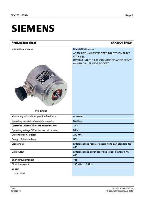
SIMODRIVE 6FX2001-5FS24 绝对值编码器多转动25位SSI操作电压10-30V
Product data sheet
product brand name
Page 1
6FX2001-5FS24
SIMODRIVE sensor ABSOLUTE VALUE ENCODER MULTITURN 25 BIT WITH SSI, OPERAT. VOLT. 10-30 V SYNCHROFLANGE SHAFT 6MM RADIAL FLANGE SOCKET
Yes Set to zero Yes 79 " (with 8192 increments) 0.01 N·m 0.01 N·m
10 N 20 N
40 N 60 N 6 mm 10 mm 100000 rad/s²
Page 2
subject to modifications © Copyright Siemens AG 2013
subject to modifications © Copyright Siemens AG 2013
6FX2001-5FS24
• with ± 1 bit accuracy / max. • with ± 100 bit accuracy / max. • mechanical / max. Length of cable to subsequent electronics • up to 1 MHz, max. • up to 100 kHz, max. • up to 300 kHz, max. • max. Digital resolution • note Telegram • note Code type • Sampling • Transfer Parameterization capability • Preset • Preset • Counting direction Accuracy • note Friction torque at 20°C / max. Starting torque at 20 °C / max. Shaft load capacity • at n > 6000 rpms • axially, max. • radially on shaft end, max. • at n ≤ 6000 rpms • axially, max. • radially on shaft end, max. External diameter / of rotary encoder shaft Length / of rotary encoder shaft Angular acceleration / maximum Moment of inertia of rotor
4M210-08

4M210-08一:产品标题:4M210-08亚德客电磁阀、4M210-08-AIRTAC电磁阀4M210-08电磁阀、亚德客4M210-08以上信息由乐清市神威气动元件厂提供!产品型号:3V1-M5|3V1-06|3V110-M5|3V120-M5|3V110-063V120-06|3V210-063|V220-06|3V210-08|3V220-08|3V310-08|3V320-08|3V310-10|3V320-10|4M110-M5|4M120-M5|4M110-06|4M120-06|4M210-06|4M220-06|4M210-08|4M220-08|4M310-08|4M320-08|4M310-10|4M320-10|4M410-15|4V110-M5|4V120-M5|4V130C-M5|4V130E-M5|4V130P-M5|4V110-06|4V120-06|4V130C-06|4V130E-06|4V130P-06|4V210-06|4V220-06|4V230C-06|4V230E-06|4V230P-06|4V210-08|4V220-08|4V230C-08|4V230E-08|4V230P-08|4V310-08|4V320-08|4V330C-08|4V330E-08|4V330P-08|4V310-10|4V320-10|4V330C-10|4V330E-10|4V330P-10|4V410-15|4V420-15|4V430C-15|4V430E-15|4V430P-15|5SV210-06|5SV220-06|5SV230C-06|5SV230E-06|5SV230P-06|5SV210-08|5SV220-08|5SV230C-08|5SV230E-08|5SV230P-08|5SV310-08|5SV320-08|5SV330C-08|5SV330E-08|5SV330P-08|5SV310-10|5SV320-10|5SV330C-10|5SV330E-10|5SV330P-10|5SV410-15|5SV420-15|5SV430C-15|5SV430E-15|5SV430P-15|产品特性:1、先导方式:内部先导式结构;2、滑柱式结构,密封性好,反应灵敏;3、三位置电磁阀有三种中央功能可供选择;4、双头二位置电磁阀具有记忆功能;5、内孔采用特殊工艺加工,磨擦阻力小,启动气压低,使用寿命长;6、无需加油润滑;7、可与底座集成阀组,节省安装空间;8、附设手动装置,利于安装调试;9、有多种标准电压等级可供选用。
亚德客电磁阀产品型号和规格简介

3V1-M5|3V1-06|3V110-M5|3V120-M5|3V110-063V120-06|3V210-063|V220-06|3V210-08|3V220-08|3V310-08|3V320-08|3V310-10|3V320-10|4M110-M5|4M120-M5|4M110-06|4M120-06|4M210-06|4M220-06|4M210-08|4M220-08|4M310-08|4M320-08|4M310-10|4M320-10|4M410-15|4V110-M5|4V120-M5|4V130C-M5|4V130E-M5|4V130P-M5|4V110-06|4V120-06|4V130C-06|4V130E-06|4V130P-06|4V210-06|4V220-06|4V230C-06|4V230E-06|4V230P-06|4V210-08|4V220-08|4V230C-08|4V230E-08|4V230P-08|4V310-08|4V320-08|4V330C-08|4V330E-08|4V330P-08|4V310-10|4V320-10|4V330C-10|4V330E-10|4V330P-10|4V410-15|4V420-15|4V430C-15|4V430E-15|4V430P-15|5SV210-06|5SV220-06|5SV230C-06|5SV230E-06|5SV230P-06|5SV210-08|5SV220-08|5SV230C-08|5SV230E-08|5SV230P-08|5SV310-08|5SV320-08|5SV330C-08|5SV330E-08|5SV330P-08|5SV310-10|5SV320-10|5SV330C-10|5SV330E-10|5SV330P-10| 5SV410-15|5SV420-15|5SV430C-15|5SV430E-15|5SV430P-15|1、先导方式:内部先导式结构;2、滑柱式结构,密封性好,反应灵敏;3、三位置电磁阀有三种中央功能可供选择;4、双头二位置电磁阀具有记忆功能;5、内孔采用特殊工艺加工,磨擦阻力小,启动气压低,使用寿命长;6、无需加油润滑;7、可与底座集成阀组,节省安装空间;8、附设手动装置,利于安装调试;9、有多种标准电压等级可供选用。
3V310-10
3V310-10亚德客电磁阀、3V310-10电磁阀神威气动3V310-10电磁阀、亚德客3V310-10产品型号:3V1-M5|3V1-06|3V110-M5|3V120-M5|3V110-063V120-06|3V210-063|V220-06|3V210-08|3V220-08|3V310-08|3V320-08|3V310-10|3V320-10|4M110-M5|4M120-M5|4M110-06|4M120-06|4M210-06|4M220-06|4M210-08|4M220-08|4M310-08|4M320-08|4M310-10|4M320-10|4M410-15|4V110-M5|4V120-M5|4V130C-M5|4V130E-M5|4V130P-M5|4V110-06|4V120-06|4V130C-06|4V130E-06|4V130P-06|4V210-06|4V220-06|4V230C-06|4V230E-06|4V230P-06|4V210-08|4V220-08|4V230C-08|4V230E-08|4V230P-08|4V310-08|4V320-08|4V330C-08|4V330E-08|4V330P-08|4V310-10|4V320-10|4V330C-10|4V330E-10|4V330P-10|4V410-15|4V420-15|4V430C-15|4V430E-15|4V430P-15|5SV210-06|5SV220-06|5SV230C-06|5SV230E-06|5SV230P-06|5SV210-08|5SV220-08|5SV230C-08|5SV230E-08|5SV230P-08|5SV310-08|5SV320-08|5SV330C-08|5SV330E-08|5SV330P-08|5SV310-10|5SV320-10|5SV330C-10|5SV330E-10|5SV330P-10|5SV410-15|5SV420-15|5SV430C-15|5SV430E-15|5SV430P-15|二:产品特性:1、先导方式:外部与内部可选;2、滑柱式结构,密封性好,反应灵敏;3、三位置电磁阀有三种中央功能可供选择;4、双头二位置电磁阀具有记忆功能;5、内孔采用特殊工艺加工,磨擦阻力小,启动气压低,使用寿命长;6、无需加油润滑;7、可与底座集成阀组,节省安装空间;8、附设手动装置,利于安装调试;9、有多种标准电压等级可供选用。
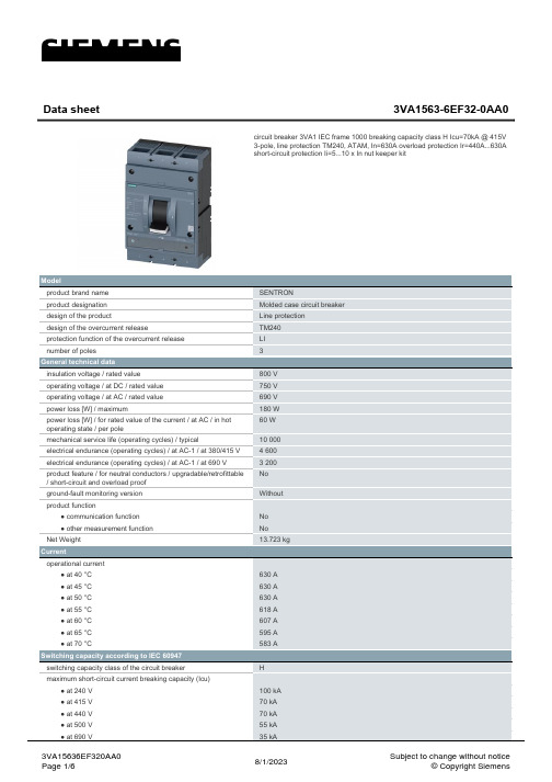
SENTRON 三极塑胶保护电路断屉 3VA1 IEC 型号说明书
Model product brand name product designation design of the product design of the overcurrent release protection function of the overcurrent release number of poles
General technical data insulation voltage / rated value operating voltage / at DC / rated value operating voltage / at AC / rated value power loss [W] / maximum power loss [W] / for rated value of the current / at AC / in hot operating state / per pole mechanical service life (operating cycles) / typical electrical endurance (operating cycles) / at AC-1 / at 380/415 V electrical endurance (operating cycles) / at AC-1 / at 690 V product feature / for neutral conductors / upgradable/retrofittable / short-circuit and overload proof ground-fault monitoring version product function ● communication function ● other measurement function Net Weight
ul310接线端子要求-2003

Page 8 of 14
UL310 中文版
9.8 对于标有符合 16.8 中所规定的公称剥线长度的绝缘端子,应将引线剥线至如表 9.3 中所规定的最大长度,然
后进行耐压测试。
表 9.3 引线的剥线长度公差
UL310 中文版
UL310 有关快速连接的端子的中文翻译
译文版本:A 参考标准:UL310 第 7 版,2003
Page 1 of 14
目录 1.适用范围 2.名词术语 3.测量单位 结构 4.总则 5.材料
5.1 母端子和公端子 5.2 标准测试公端子 6.尺寸 6.1 总则 6.2 公端子 6.3 标准测试公端子 7.绝缘 性能 8.总则 9.样板的准备 10.端子和引线分离的拉力测试 11.插入-拔出测试 12.温度和热循环测试 12.1 总则 12.2 温度测试 12.3 热循环测试 13. 耐压测试 13.1 总则 13.2 绝缘击穿测试 13.3 耐压测试(类型 A) 13.4 耐压测试(类型 B-管状套管) 14.绝缘紧固性测试 14.1 总则 14.2 具有非管状套管绝缘的端子 14.3 具有管状套管绝缘的端子 15.潮湿-吸湿测试 标志 16. 标志 指引 17.装配指引
2. 名词术语
2.1 本标准采用以下列定义.
2.2 毛刺-在端子上的无关系的凸出,被认为不是母端子或是公端子的功能组成部分。 2.3 母端子-通过推进而和公端子连接的端子 2.4 C2600 合金-铜锡合金,按照美国铜业发展委员会的 CDA 标准手册规定,由大约 70%的铜和 30%的锡组成. 2.5 锁扣-在公端子上的凹槽或是孔,用于咬合母端子上的凸缘,以使公端子和母端子之间能够锁紧。 2.6 公端子-插入母端子的端子,按照指定的公差来制造,目的在于通过和母端子的配接来建立电气连接。 2.7 快速连接端子:由公端子和母端子组成,无须使用工具就可以容易地插入和拔出端子的一种电气连接. 2.8 参考点-在母端子和公端子上的标识点,作为电气性能测试的测量参考。 2.9 端子-一种电气连接部件(装置),由公端子或是母端子组成。 2.10 测试标准公端子-根据指定的公差进行制造的公端子,为母端子的电气性能测试,机械性能测试和温升测 试提供精确的基准。
4V110-06

4V110-06一:产品标题:4V110-06亚德客电磁阀、4V110-06-AIRTAC电磁阀4V110-06电磁阀、亚德客4V110-06以上信息由乐清市神威气动元件厂提供!产品型号:3V1-M5|3V1-06|3V110-M5|3V120-M5|3V110-063V120-06|3V210-063|V220-06|3V210-08|3V220-08|3V310-08|3V320-08|3V310-10|3V320-10|4M110-M5|4M120-M5|4M110-06|4M120-06|4M210-06|4M220-06|4M210-08|4M220-08|4M310-08|4M320-08|4M310-10|4M320-10|4M410-15|4V110-M5|4V120-M5|4V130C-M5|4V130E-M5|4V130P-M5|4V110-06|4V120-06|4V130C-06|4V130E-06|4V130P-06|4V210-06|4V220-06|4V230C-06|4V230E-06|4V230P-06|4V210-08|4V220-08|4V230C-08|4V230E-08|4V230P-08|4V310-08|4V320-08|4V330C-08|4V330E-08|4V330P-08|4V310-10|4V320-10|4V330C-10|4V330E-10|4V330P-10|4V410-15|4V420-15|4V430C-15|4V430E-15|4V430P-15|5SV210-06|5SV220-06|5SV230C-06|5SV230E-06|5SV230P-06|5SV210-08|5SV220-08|5SV230C-08|5SV230E-08|5SV230P-08|5SV310-08|5SV320-08|5SV330C-08|5SV330E-08|5SV330P-08|5SV310-10|5SV320-10|5SV330C-10|5SV330E-10|5SV330P-10|5SV410-15|5SV420-15|5SV430C-15|5SV430E-15|5SV430P-15|二:产品特性:1、先导方式:外部与内部可选;2、滑柱式结构,密封性好,反应灵敏;3、三位置电磁阀有三种中央功能可供选择;4、双头二位置电磁阀具有记忆功能;5、内孔采用特殊工艺加工,磨擦阻力小,启动气压低,使用寿命长;6、无需加油润滑;7、可与底座集成阀组,节省安装空间;8、附设手动装置,利于安装调试;9、有多种标准电压等级可供选用。
亚德客选型电子手册
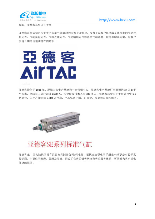
标题:亚德客选型电子手册亚德客是全球知名专业生产各类气动器材的大型企业集团,致力于向客户提供满足其需求的气动控制元件、气动执行元件、气源处理元件、气动辅助元件等各类气动器材、服务和解决方案,为客户创造长期的价值和潜在的增长。
亚德客始创于1988年,现辖三大生产基地和一家营销中心,亚德客生产基地厂房面积达37万8千平方米,全球员工总计超过4500人,专业研发技术人员300多人,亚德客选型电子手册总投资1.5亿美元,年生产能力达5,000万件套,产品畅销中国、东南亚、欧美等国家和地区。
亚德客在中国大陆地区拥有近百家直销分公司/营业部,亚德客选型电子手册在全球更是有数千家经销商,主要位于欧洲、美洲及亚洲,形成了完善的销售网络和售后服务体系,可随时为客户提供便捷的服务。
亚德客以拓展集团生产和服务为未来发展的战略目标,坚持走人本优先、改革创新和集团化道路。
秉承“人本、共享、发展、责任”的企业核心价值观,亚德客始终如一地贯彻“以客为尊”的经营理念,始终如一地坚持“以技术创新为核心,亚德客选型电子手册以市场需求为导向”的经营方针,藉以不断完善“建立共好、责任承担、赏罚分明、学习成长”的集团文化,努力奋斗,自强不息,长久致力于全球工业自动化的持续发展。
台湾亚德客工业股份有限公司(简称台亚)成立于1988年11月,前身系健良股份有限公司,1990年更名为台亚。
早期的台亚主要生产电磁阀,此后亚德客选型电子手册陆续研发生产气缸、气源处理等产品。
目前,台亚产品以特殊规格气缸为主,拥有七大类十余系列数百个品种,年产量达到20万件套,主要供应台湾本地市场,满足客户需求及时效性。
1998年,台亚在同行中率先通过“ISO9000质量管理体系认证”;2004年,台亚取得“ISO14000环境体系认证”及“CE认证”。
长期以来,台亚秉持“质量第一、交货准时”的服务精神及理念满足客户需求,亚德客选型电子手册不断引进先进设备、生产工艺提升产品质量与品质。
4V230E-06

4V230E-06亚德客电磁阀神威气动4V230E-06电磁阀、亚德客4V230E-06产品型号:3V1-M5|3V1-06|3V110-M5|3V120-M5|3V110-063V120-06|3V210-063|V220-06|3V210-08|3V220-08|3V310-08|3V320-08|3V310-10|3V320-10|4M110-M5|4M120-M5|4M110-06|4M120-06|4M210-06|4M220-06|4M210-08|4M220-08|4M310-08|4M320-08|4M310-10|4M320-10|4M410-15|4V110-M5|4V120-M5|4V130C-M5|4V130E-M5|4V130P-M5|4V110-06|4V120-06|4V130C-06|4V130E-06|4V130P-06|4V210-06|4V220-06|4V230C-06|4V230E-06|4V230P-06|4V210-08|4V220-08|4V230C-08|4V230E-08|4V230P-08|4V310-08|4V320-08|4V330C-08|4V330E-08|4V330P-08|4V310-10|4V320-10|4V330C-10|4V330E-10|4V330P-10|4V410-15|4V420-15|4V430C-15|4V430E-15|4V430P-15|5SV210-06|5SV220-06|5SV230C-06|5SV230E-06|5SV230P-06|5SV210-08|5SV220-08|5SV230C-08|5SV230E-08|5SV230P-08|5SV310-08|5SV320-08|5SV330C-08|5SV330E-08|5SV330P-08|5SV310-10|5SV320-10|5SV330C-10|5SV330E-10|5SV330P-10| 5SV410-15|5SV420-15|5SV430C-15|5SV430E-15|5SV430P-15|二:产品特性:1、先导方式:外部与内部可选;2、滑柱式结构,密封性好,反应灵敏;3、三位置电磁阀有三种中央功能可供选择;4、双头二位置电磁阀具有记忆功能;5、内孔采用特殊工艺加工,磨擦阻力小,启动气压低,使用寿命长;6、无需加油润滑;7、可与底座集成阀组,节省安装空间;8、附设手动装置,利于安装调试;9、有多种标准电压等级可供选用。
3T31安装手册资料

安装、操作和维修手册卡麦隆31 型全焊接球阀卡麦隆 31 型全焊接球阀安装、操作和维修手册第一版号TC1411 第一版号 TC1411 1999年7月第一版○c库博 .卡麦隆公司 , 库博 .卡麦隆阀门部 , 1999保存全部权目录主要零件------------------------- 4概括--------------------------- 5名牌信息------------------------- 5储藏--------------------------- 5安装--------------------------- 6第一版号 TC1411卡麦隆31型全焊接球阀安装、操作和维修手册保护---------------------------9故障剖析-------------------------11 主要零零件图图 1- 库博 .卡麦隆阀门卡麦隆全焊接球阀详尽零件图序号描绘1 键轴2 上部阀杆密封3 上部阀体4 下部阀杆密封第一版号 TC1411 卡麦隆 31 型全焊接球阀安装、操作和维修手册5阀杆轴承6拨齿7阀球8阀座环9唇式密封10联接端部11下部阀体*阀杆详尽请件第 18 和 19 页第一版号 TC1411卡麦隆31型全焊接球阀安装、操作和维修手册卡麦隆全焊接球阀概括享誉石油行业的库博. 卡麦隆全焊接阀门将轻质高强的锻钢阀门零件与紧凑的球型阀体设计完美的集于一体。
卡麦隆全焊接阀门知足ANSI 150至2500(PN20至PN420)及API2000至5000 标准的要求。
阀体采纳锻钢材质, 保证了资料内部金属晶粒的平均一致和持久耐用。
卡麦隆全焊接球阀的尺寸范围为2”至 56”( DN50 至 1400 )。
设计知足苛刻条件并免维修的卡麦隆全焊接阀门可在多种工况采纳。
卡麦隆全焊接阀门的独到设计使其同时拥有最大的强度和最小的重量,并拥有最大的抵挡管线压力和应力的能力。
紧凑球型的阀体设计防止了阀体联接法兰,所以减小了阀门外形尺寸和除去了泄漏渠道。
Fieldpiece SVG3 真空表 产品使用指南说明书
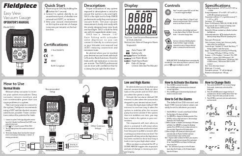
010306020504070912081110Directly to Service PortSchrader Core Removal Tool Hose To PumpFieldpieceVACUUM GAUGEALARMENTERQuick Start1. Power on your SVG3 by holding thebutton for 1 second. 2. C onnect to system directly to an unused service port, a Schrader core removal tool (SCRT), or via hoses.3. View your vacuum measurement on the top line and rate of change (±microns per minute) on the bot-tom line.CertificationsC-Tick (N22675) CEWEEERoHS CompliantDescription Proper evacuation of any system exposed to atmosphere is critical to ensure the system is dry and tight.SVG3 is the right tool to help HVACR professionals verify they reach proper vacuum levels. See your vacuum measurement clearly and easily with the newly designed easy-view hook and backlight. SVG3 is built for field use with its ruggedized rubber case. S V G 3 h a s a f e m a l e 1/4" f l a r e f i t t i n g w i t h s c h r a d e r v a l v e d e p r e s s o r s o y o u c a n connect it directly to a service port or your Schrader core removal tool (SCRT) reducing connections and minimizes leaksBe alerted when you've reachedyour desired vacuum levels with built in Hi and Lo Alarm functions. Check forleaks with rate indication in microns per minute. The HVACR professional can do more with confidence that he is doing the job right the first time.DisplayTop Line:Live Vacuum Measurement in Units selected Bottom Line: Rate of Change or AlarmStopwatch Auto Power Off Battery Life Alarm Set Mode Low Alarm Mode High Alarm Mode Rate of Change (±Units Selected Per Minute)FieldpieceEasy View Vacuum GaugeOPERATOR'S MANUALModel SVG3ControlsHold 1 second to power SVG3 on/ o ff. Press <1 second to toggle backlight. Press to activate Alarm Lo, Alarm Hi, andreturn to real time mode. Hold 1 second toenter or exit Alarm Set mode.Press to lock in selected digit and move to next digit in Alarm Set Mode. Press and hold >1 second to Change Units.Increase or decrease blinking digit in Alarm Set Mode. Toggle to displaystopwatch or rate of change when an alarm is activated in real time mode.BACKLIGHT NOTE: T he backlight timer is automaticallyextended for 1 min when any button is pressed. A short press of toggles backlight on and off.SpecificationsOperating temperature: 32°F (0°C) to 122°F (50°C) at <75%RHStorage temperature: -4°F to 140°F (-20°C to 60°C), 0 to 80% RH (with battery removed)Temperature coefficient: 0.1 x (specified accuracy)/°C (<18°C or >28°C)Over range: "OL" is displayedPower: 4 x AAA batteries, NEDA 24A, JIS UM4, IEC R03 Auto power off: after 15 minutes of readings more than 10,000 microns if APO is active.Battery life: 40 hours standard use (alkaline) without backlight use.Low battery indication: is displayed when the battery voltage drops below the operating level.Vacuum PressureUnits of measure: microns (µm) of mercury, mmHg,mbar, mTorr, Torr, and PascalsConnector type: Standard 1/4" female flare fitting. "T" fitting included ( 3 male flare ports)Range: 0 to 9999 microns of mercury (9.999 mmHg, 13.33 mbar, 9999 mTorr, 9.999 Torr, 1333 Pa)Accuracy: ±(5% of reading + 5 microns), 50 to 1000Resolution: 1 micron (50 to 2000 microns), 250microns (2001 to 5000 microns), 500 microns (5001 to 8000 microns), 1000 microns (8001 to 9999 microns)Rate: Units selected per minute Refresh rate: 0.5 secondsAtmospheric pressure: "OL" will be displayed Maximum overload pressure: 500 psig How to UseNormal ModeMeasure deep vacuums to moni-tor your system evacuations. Deepvacuums remove moisture and non-condensable gases that can cause problems in a system.There are many ways to connect to the system, Fieldpiece recommends using a SCRT and the shortest vacuum rated hoses possible. Fewer connec-tions reduce the potential for leaks.1. Connect to system. Techs typically prefer connect-ing to the Schrader Core Removal Tool (SCRT) or an unused service port.2. Hold for 1 second to power ON the SVG3.3. The top display shows the vacuum in microns of mercury.4. The bottom display shows how fast the measure-ment is increasing or decreasing (± microns of mercury per minute).Low and High Alarms Be alerted when you've reached yourdesired vacuum levels. Work on other tasks at the jobsite and let SVG3 alert you when the system is ready.Activate the low alarm (default 500 microns) to alert when the vacuum has dropped to your desired micron level.Activate the high alarm (default 1000 microns) to see how long it takes the system to stabilize after the vacuum pump has been isolated. If the system does not stabilize over time, you may have a leak in the system or your con-nections.The stopwatch will start when analarm is activated. It will restart whenthe low alarm has been reached to show how long you've pulled a vacuum after reaching your desired micron level. The stopwatch will stop when the high alarm has been reached to show how long it took to rise to your high alarm value.When an alarm is activated the UP or DOWN ARROW toggles the stopwatch and rate of change (± microns per min-ute) display. How to Activate the Alarms1. Press ALARM to activate low alarm.2. Press ALARM again to deactivate low alarm and activate high alarm.3. Press ALARM again to deactivate high alarm and return to real time mode.How to Set the AlarmsThe default low (500 microns) and high (1000 microns) alarm values can easily be set to whatever you want.1. Hold ALARM for 1 second to enter Alarm Set Mode. The first digit of LO alarm will blink.2. Use ARROWS to change the blinking number. Press ENTER to lock in a digit and move to the next digit. Repeat for all LO alarm digits.3. When LO alarm is complete, the first digit of HI alarm will blink. Use ARROWS to change the blinking number. Press ENTER to lock in a digit and move to the next digit. Repeat for all HI alarm digits.4. When all digits of HI alarm are locked in you will automatically exit Alarm Set Mode and your customized alarm values will be saved.Note: Anytime while in Alarm Set Mode, you can press ALARM to toggle between alarm HI set and alarm LO set. Hold ALARM to exit Alarm Set Mode and save at any time.Note: "Err" will show if you try to set the HI alarm lower than the LO alarm, or the LO alarm higher than the HI alarm.How to Change Units1. Press and hold ENTER (>1 sec) to enter Change Units mode. Current units selected will be displayed.2. Press UP or DOWN arrow to toggle the list of available units. Microns-mmHg-mbar-mTorr-Torr-Pascals. Stop on the units you want to select.3. Press ENTER to save units selection and return to real time mode.SVG3FieldpieceVACUUM GAUGEALARMENTERSVG3FieldpieceVACUUM GAUGE MINALARMENTER UNITS SVG3Fieldpiece VACUUM GAUGE MIN ALARM ENTER UNITS SVG3Fieldpiece VACUUM GAUGEMINALARMENTER UNITSSVG3FieldpieceVACUUM GAUGE MIN ALARMENTERUNITS (tool not included)RecommendedSetupFieldpieceFieldpieceTo PumpT oService PortHose toRemoval T oolSVG3FieldpieceVACUUMGAUGEMINALARMENTER UNITS SVG3Fieldpiece VACUUMGAUGEMINALARMENTERUNITSSVG3Fieldpiece VACUUM GAUGE MIN ALARM ENTER UNITS SVG3Fieldpiece VACUUM GAUGE MINALARM ENTER UNITS SVG3Fieldpiece VACUUMGAUGE MINALARMENTER UNITS SVG3Fieldpiece VACUUM GAUGE MIN ALARM ENTER UNITS SVG3Fieldpiece VACUUMGAUGEMINALARM ENTER UNITS SVG3Fieldpiece VACUUMGAUGEMIN ALARMENTERUNITSSVG3Fieldpiece VACUUMGAUGE MINALARMENTER UNITSSVG3Fieldpiece VACUUMGAUGEMINALARMENTERUNITSSVG3Fieldpiece VACUUM GAUGEALARMENTERUNITSOther Common Setups Microns mm of Mercury (Hg)millibar milliTorrTorrPascals131518141716192124202322indoor air. The refrigerant stays at the same temperature and pressure until all the refrigerant evaporates into a gas. After the refrigerant becomes a gas, it will continue to absorb heat and become superheated at which point its temperature will change. The Superheat measurement is the best indication of refrigerant charge level in a fixed restrictor system. A TXV/EXV system will keep the superheat constant. There must be superheat present to ensure liquid does not flood the compressor.Superheat measurements are taken on the suction line between the evaporator and compressor.The compressor takes this low tem-perature, low pressure, slightly super-heated refrigerant and compresses it to a much higher temperature and pressure.The highly superheated gas enters the condenser and rejects heat into the outside air. The refrigerant con-denses back into a liquid. Once all of the gas is condensed into a liquid,Vacuum TipsFollow all manufacturer's evacu-ation procedures over those in this manual in regards to specifications on how to evacuate systems. To achieve a deep vacuum efficiently Fieldpiece recommends the following practices.1. Remove Schrader valves from the system service ports using a valve core removal tool (purchased separately).2. Use the shortest vacuum rated hoses with the largest diameter available.3. Inspect rubber seals at both ends of your hoses for damage that may result in leakage.4. Avoid using hoses with low loss fittings when evacuating a system.5. Avoid over-tightening the female flare fitting of the SVG3. Over-tightening may cause the rubber gasket to wear more quickly and create leaks. It is not necessary to over tighten SVG3 to the extreme to create a good seal.Replacement PartsThe rubber gasket and Schrader valve depressor are user-replaceable. Worn out rubber gaskets can cause leaks due to a bad seal. Over-tight-ening of the SVG3 female flare fitting may cause the rubber gasket to wear more quickly or damage the fitting itself. Replace if the rubber gasket becomes worn. The rubber gasket (standard 1/4" gasket used in refriger-ant hoses) can easily be found at your local HVACR distributor.1. Remove both the Schrader valve depressor and rubber gasket from the SVG3 cup. Dispose of worn rubber gasket. A small pair of needle nose plyers may used to pull out the valve depressor and the gasket. Be careful not damage the Schrader valve depressor.2. Position the new rubber gasket into the top of the cup. Push in with your finger until rubber gasket is at the bottom of the cup.3. Insert Schrader valve depressor into the rubber gasket hole. Push Schrader depressor to the bottom of the cup with your finger. You may use a pocket SCRT to "screw" in the Schrader valve depressor if needed.A/C BasicsThe Evaporator, Condenser, Restric-tor (Throttling valve) and Compressor are the four basic components of an air conditioner. Following one pound of refrigerant through the system shows the function of each component.Subcooled liquid refrigerant at high pressure enters the restrictor and is throttled to saturated refrigerant at a lower pressure. The restrictor can be either a fixed or TXV/EXV type. The fixed type must be charged to a target superheat that varies with indoor and outdoor conditions. TXV/EXV systems must be charged to subcooling.The evaporator capacity varies with the indoor heat load on a fixed restric-tor. The TXV/EXV regulates the size of the restriction to maintain a constant superheat. This essentially adjusts the capacity of the evaporator responding to the indoor heat load.After the restrictor, refrigerant enters the evaporator at a low temperature and pressure, and boils (evaporates) into a gas by absorbing heat from theadditional removal of heat causes a temperature drop that is known as subcooling. TXV/EXV systems are charged to subcooling since super-heat is controlled by the throttle valve. Subcooling measurements are taken on the liquid line between the condenser and TXV/EXV. Finally, the subcooled liquid enters the restrictor and the cycle starts again.Limited WarrantyThis meter is warranted against defects in material or workmanship for one year from date of purchase. Fieldpiece will replace or repair the defective unit, at its option, subject to verification of the defect.This warranty does not apply to defects resulting from abuse, ne-glect, accident, unauthorized repair, alteration, or unreasonable use of the instrument.Any implied warranties arising from the sale of a Fieldpiece product, including but not limited to implied warranties of merchantability and fitness for a particular purpose, are limited to the above. Fieldpiece shall not be liable for loss of use of the instrument or other incidental or consequential damages, expenses, or economic loss, or for any claim of such damage, expenses, or economic loss. State laws vary. The above limita-tions or exclusions may not apply to you.For ServiceIn the USA, call Fieldpiece Instru-ments for one-price-fix-all out of war-ranty service pricing. Send check or money order for the amount quoted. Send the meter freight prepaid to Fieldpiece Instruments. Send proof of date and location of purchase for in-warranty service. The meter will be repaired or replaced, at the option of Fieldpiece, and returned via least cost transportation.For international customers, war-ranty for products purchased outside of the U.S. should be handled through local distributors.© Fieldpiece Instruments, Inc 2015; v26More Great Tools from FieldpieceMaintenanceClean the exterior with a dry cloth. Do not use liquid.Battery ReplacementPower off SVG3. Unscrew battery cover, and replace the 4 AAA batteries.Battery Cover Screw!Cleaning the Sensor1. Turn off your SVG3.2. Remove the Schrader valve depressor and rubber gasket. A small pair of needle nose plyers can easily pull out the depressor and the gasket at the same time. Be careful to not puncture or tear the gasket.3. Fill the cavity halfway with isopropyl (rubbing) alcohol.4. Use your index finger to cover female flare fitting and gently swirl and shake the alcohol within the cavity for about 15 to 30 seconds.5. Pour out the alcohol and let the vacuum sensor dry with the flare fitting facing down.6. Install rubber gasket and valve depressor using Replacement Parts section instructions.Note: Do not use an object such as a cotton swab to clean the sensor. This may damage the sensor. EVAPORATORCONDENSERTHROTTLE VALVECOMPRESSORREFRIGERANT FLOWH i gh P re s s u r eS i d eL o w P r es s u re Si d e RETURN AIR SUPPLY AIROUTDOOR AIR HOT AIRWireless Refrigerant ScaleModel SRS2CDual In-Duct PsychrometerModel SDP2Wireless 4-Port Manifold ModelSMAN460Infrared Refrigerant Leak DectectorModel SRL2K7PE AKMU TEON /O FFL/M /H。
3口空气驱动自动阀门说明书
Doc. no. VP3145-OMH0005-D3 Port Air Operated ValveSeries: VPA31∗5Safety Instructions ---------------------------------------------------------------------------------- 2,3 Design -------------------------------------------------------------------------------------------------- 4 Selection ----------------------------------------------------------------------------------------------- 4 Mounting ----------------------------------------------------------------------------------------------- 4 Piping --------------------------------------------------------------------------------------------------- 5 Lubrication --------------------------------------------------------------------------------------------- 5 Air Supply --------------------------------------------------------------------------------------------- 5 Operating Environment----------------------------------------------------------------------------- 5 Maintenance ------------------------------------------------------------------------------------------- 5 Specific Product Precautions ---------------------------------------------------------------------- 6,7 Trouble shooting -------------------------------------------------------------------------------------- 8 Remedy ------------------------------------------------------------------------------------------------- 9Safety InstructionsThese safety instructions are intended to prevent hazardous situations and/or equipment damage.These instructions indicate the level of potential hazard with the labels of “Caution,” “Warning” or “Danger.” They are all important notes for safety and must be followed in addition to International Standards (ISO/IEC)*1) , and other safety regulations.*1) ISO 4414: Pneumatic fluid power -- General rules relating to systems. ISO 4413: Hydraulic fluid power -- General rules relating to systems.IEC 60204-1: Safety of machinery -- Electrical equipment of machines .(Part 1: General requirements)ISO 10218: Manipulating industrial robots -Safety. etc.Caution Caution indicates a hazard with a low level of risk which, if not avoided, could resultin minor or moderate injury.Warning Warning indicates a hazard with a medium level of risk which, if not avoided, could result in death or serious injury.DangerDanger indicates a hazard with a high level of risk which, if not avoided, will resultin death or serious injury.Warning 1. The compatibility of the product is the responsibility of the person who designs the equipment ordecides its specifications.Since the product specified here is used under various operating conditions, its compatibility with specific equipment must be decided by the person who designs the equipment or decides its specifications based on necessary analysis and test results.The expected performance and safety assurance of the equipment will be the responsibility of the person who has determined its compatibility with the product.This person should also continuously review all specifications of the product referring to its latest catalog information, with a view to giving due consideration to any possibility of equipment failure when configuring the equipment.2. Only personnel with appropriate training should operate machinery and equipment.The product specified here may become unsafe if handled incorrectly.The assembly, operation and maintenance of machines or equipment including our products must be performed by an operator who is appropriately trained and experienced.3. Do not service or attempt to remove product and machinery/equipment until safety is confirmed.1.The inspection and maintenance of machinery/equipment should only be performed after measures to prevent falling or runaway of the driven objects have been confirmed.2.When the product is to be removed, confirm that the safety measures as mentioned above are implemented and the power from any appropriate source is cut, and read and understand the specific product precautions of all relevant products carefully.3. Before machinery/equipment is restarted, take measures to prevent unexpected operation and malfunction.4. Contact SMC beforehand and take special consideration of safety measures if the product is to be used in any of the following conditions.1. Conditions and environments outside of the given specifications, or use outdoors or in a place exposed to direct sunlight.2. Installation on equipment in conjunction with atomic energy, railways, air navigation, space, shipping, vehicles, military, medical treatment, combustion and recreation, or equipment in contact with food and beverages, emergency stop circuits, clutch and brake circuits in press applications, safety equipment or other applications unsuitable for the standard specifications described in the product catalog.3. An application which could have negative effects on people, property, or animals requiring special safety analysis.e in an interlock circuit, which requires the provision of double interlock for possible failure by using a mechanical protective function, and periodical checks to confirm proper operation.Safety InstructionsCaution1. The product is provided for use in manufacturing industries.The product herein described is basically provided for peaceful use in manufacturing industries.If considering using the product in other industries, consult SMC beforehand and exchange specifications or a contract if necessary.If anything is unclear, contact your nearest sales branch.Limited warranty and Disclaimer/Compliance RequirementsThe product used is subject to the following “Limited warranty and Disclaimer” and “Compliance Requirements”.Read and accept them before using the product.Limited warranty and Disclaimer1.The warranty period of the product is 1 year in service or 1.5 years after the product is delivered,whichever is first.∗2)Also, the product may have specified durability, running distance or replacement parts. Please consult your nearest sales branch.2. For any failure or damage reported within the warranty period which is clearly our responsibility,a replacement product or necessary parts will be provided.This limited warranty applies only to our product independently, and not to any other damage incurred due to the failure of the product.3. Prior to using SMC products, please read and understand the warranty terms and disclaimers noted in the specified catalog for the particular products.∗2) Vacuum pads are excluded from this 1 year warranty.A vacuum pad is a consumable part, so it is warranted for a year after it is delivered.Also, even within the warranty period, the wear of a product due to the use of the vacuumpad or failure due to the deterioration of rubber material are not covered by the limitedwarranty.Compliance Requirements1. The use of SMC products with production equipment for the manufacture of weapons of massdestruction(WMD) or any other weapon is strictly prohibited.2. The exports of SMC products or technology from one country to another are governed by therelevant security laws and regulation of the countries involved in the transaction. Prior to the shipment of a SMC product to another country, assure that all local rules governing that export are known and f ollowed.CautionSMC products are not intended for use as instruments for legal metrology.Measurement instruments that SMC manufactures or sells have not been qualified by type approval tests relevant to the metrology (measurement) laws of each country.Therefore, SMC products cannot be used for business or certification ordained by the metrology (measurement) laws of each country.WarningWarningDesign / Selection1. Confirm the specifications. Products represented in this manual are designed only for use in compressed air systems (including vacuum).Do not operate at pressures or temperatures, etc., beyond the range of specifications, as this can cause damage or malfunction. (Refer to the specifications.)Please contact SMC when using a fluid other than compressed air (including vacuum).We do not guarantee against any damage if the product is used outside of the specification range.2. Actuator driveWhen an actuator, such as a cylinder, is to be driven using a valve, take appropriate measures (cover installation or approach prohibition) to prevent potential danger caused by actuator operation.3. Holding pressure (including vacuum)Since the valves are subject to air leakage, they cannot be used for applications such as holding pressure (including vacuum) in a pressure vessel.4. Not suitable for use as an emergency shutoff valve, etc.The valves listed in this manual are not designed for safety applications such as an emergency shutoff valve. If the valves are used for the mentioned applications, additional safety measures should be adopted.5. Release of residual pressureFor maintenance purposes install a system for releasing residual pressure.6. Operation in a vacuum conditionWhen a valve is used for switching a vacuum, take measures to install a suction filter or similar to prevent external dust or other foreign matter from entering inside the valve. In addition, at the time of vacuum adsorption, be sure to vacuum at all times. Failure to do so may result in foreign matter sticking to the adsorption pad, or air leakage causing the workpiece to drop.7. Regarding a vacuum switch valve and a vacuum release valveIf a non-vacuum valve is installed in the middle of piping system having a vacuum, the vacuum condition will not be maintained. Use a valve designed for use under vacuum condition.8. VentilationProvide ventilation when using a valve in a confined area, such as in a closed control panel. For example, install a ventilation opening, etc. in order to prevent pressure from increasing inside of the confined area.9 .Do not disassemble the product or make any modifications, including additional machining.Doing so may cause human injury and/or an accident. When the product is disassembled for maintenance, refer to “Overhaul / Cleaning / Addition of grease (VPA31*5V series: Vacuum Specification)”.Selection1. Use in low temperature environments Valve use is possible to temperature to 0o C. Take appropriate measures to avoid freezing or congealing of drain, water, etc.2. Pilot airThe pilot port should be pressurized by a compressed air at the specified pressure.3. Mounting orientationMounting orientation is free.Mounting1. Operation manualInstall the products and operate them only after reading the operation manual carefully and understanding its contents. Also, keep the manual where it can be referred to as necessary.2. Ensure sufficient space for maintenance activities.When installing the products, allow access for maintenance.3. Tighten threads with the proper tightening torque.When installing the products, follow the listed torque specifications.4. If air leakage increases or equipment does not operate properly, stop operation.Check mounting conditions when air and power supplies are connected. Initial function and leakage tests should be performed after installation.5. Painting and coatingWarnings or specifications printed or affixed to the product should not be erased, removed or covered up.Please consult with SMC before applying paint to resinous parts, as this may have an adverse effect due to the solvent in the paint.Be sure to read before handling.CautionWarningWarningPiping1. Preparation before pipingBefore piping is connected, it should be thoroughly blown outwith air (flushing) or washed to remove chips, cutting oil andother debris from inside the pipe.2. Wrapping of pipe tapeWhen screwing piping orfittings into ports, ensure thatchips from the pipe threads orsealing material do not enterthe piping. Also, if pipe tape isused, leave 1 thread ridgesexposed at the end of thethreads.3. Connection of fittingsWhen screwing fittings into valves, tighten as follows.Tightening Torque for PipingConnection thread size (R, NPT)Proper tightening torque (N·m)1/8 3~53/8 15~201/2 20~253/4 28~301 36~381 1/440~421 1/248~502 48~50Follow the procedure of the manufacturer when fittings other thanSMC is used.1) If the fitting is tightened with excessive torque, a large amountof sealant will seep out. Remove the excess sealant.2) Insufficient tightening may cause seal failure or loosen thethreads.3) For reuse(1) Normally, fittings with a sealant can be reused up to 2 to 3times.(2) To prevent air leakage through the sealant, remove anyloose sealant stuck to the fitting by blowing air over thethreaded portion.(3) If the sealant no longer provides effective sealing, windsealing tape over the sealant before reusing. Do not use anyform of sealant other than the tape type of sealant.(4) Once the fitting has been tightened, backing it out to itsoriginal position often causes the sealant to becomedefective. Air leakage will occur.4. Uni thread fittings1) First, tighten the threaded portion by hand, then use a suitablewrench to tighten the hexagonal portion of the body further atwrench tightening angle shown below. For the reference valuefor the tightening torque, refer to the table below.Connection Female Thread: Rc, NPT, NPTFUni thread sizeWrench tightening angleafter tightened by hand(deg)Tightening torque(N·m)1/8 30 to 60 3 to 53/8 15 to 45 14 to 161/2 15 to 30 20 to 22Connection Female Thread: GUni thread sizeWrench tightening angleafter tightened by hand(deg)Tightening torque(N·m)1/8 30 to 45 3 to 43/8 15 to 30 8 to 91/2 15 to 3014 to 152) The gasket can be reused up to 6 to 10 times. It can bereplaced easily when it has sustained damage. A broken gasketcan be removed by holding it and then turning it in the samedirection as loosening the thread. If the gasket is difficult toremove, cut it with nippers, etc. In such a case, use caution notto scratch the seat face because the seat face of the fitting’s45° gasket is the sealing face.5. Piping to productsWhen piping to a product, refer to the operation manual toavoid mistakes regarding the supply port, etc.LubricationThis is a valve which requires lubrication. Besure to lubricate it for operation.It may cause problems such as damage andmalfunction of the valve if it is not lubricated.A valve of vacuum specification needs overhaulfor cleaning and addition of grease because itcannot be lubricated without it. (Refer to page 8.)1) If a lubricant is used in the system, use class 1 turbine oil (noadditive), ISO VG32.2) Please contact SMC regarding class 2 turbine oil (withadditives), ISO VG32.Lubrication amountIf too much oil is supplied, the oil will be accumulated in theproduct, causing malfunction or response delay.Air Supply1. Use clean air.Do not use compressed air that contains chemicals, syntheticoils including organic solvents, salt or corrosive gases, etc., asit can cause damage or malfunction.1. Install an air filter.Install an air filter upstream near the valve. Select an air filterwith a filtration size of 5 ㎛or smaller.2. Take measures to ensure air quality, such as byinstalling an aftercooler, air dryer, or waterseparator.Compressed air that contains a large amount of drainage cancause malfunction of pneumatic equipment such as valves.Therefore, take appropriate measures to ensure air quality,such as by providing an aftercooler, air dryer, or waterseparator.Be sure to read before handling.CautionCautionWarningWarningAir Supply3. If excessive carbon powder is seen, install a mist separator on the upstream side of the valve.If excessive carbon dust is generated by the compressor, it may adhere to the inside of a valve and cause it to malfunction.For compressed air quality, refer to SMC’s Best Pneumatics catalog.Operating Environment1. Do not use in an atmosphere having corrosivegases, chemicals, sea water, water, water steam, or where there is direct contact with any of these . 2. Do not use in an environment where flammable gas or explosive gas exists. Usage may cause a fire or explosion.The products do not have an explosion proof construction.3. Do not use in a place subject to heavy vibration and/or shock.4. The valve should not be exposed to prolonged sunlight. Use a protective cover.Note that the valve is not for outdoor use. 5. Remove any sources of excessive heat.6. If it is used in an environment where there is possible contact with a waterdrop, oil, weld spatter, etc., exercise preventive measures.(1) Temperature of ambient environmentUse the valve within the range of the ambient temperature specification of each valve. In addition, pay attention when using the valve in environments where the temperature changes drastically.(2) Humidity of ambient environmentIf the humidity rises, take measures to prevent the adhesion of water droplets on the valve.Maintenance1. Perform maintenance inspection according to the procedures indicated in the operation manual.If handled improperly, malfunction and damage of machinery or equipment may occur.2. Removal of equipment, and supply/exhaust of compressed airWhen components are removed, first confirm that measures are in place to prevent workpieces from dropping, run-away equipment, etc. Then, cut off the supply pressure and electric power, and exhaust all compressed air from the system using the residual pressure release function.When the equipment is operated after remounting or replacement, first confirm that measures are in place to prevent lurching of actuators, etc. Then, confirm that the equipment is operating normally.3. Low frequency operationValves should be operated at least once every 30 days to prevent malfunction. (Use caution regarding the air supply.)4. If the volume of air leakage increases or the valve does not operate normally, do not use the valve.Perform periodic maintenance on the valve to confirm the operating condition and check for any air leakage.1. Drain flushing Remove drainage from the air filters regularly.CautionCautionCautionVPA31∗5 SeriesPrecautions for 3 Port Air Operated Valve ③Be sure to read before handling.Other Precautions1. Pressure balance among each portThis valve is pressure-unbalanced type. Operate it within this pressure range: IN ≧ OUT ≧ EXH. If not operated in the range, the valve will malfunction.2. Use as 2 port valve1) Plug EXH port in case of pressure-in and plug IN port in case of vacuum use.2) This valve has slight air leakage and can not be used for such purposes as holding air pressure (including vacuum) in the pressure container.3. Piping (Vacuum Use)1) Piping in general:Vacuum pump/BlowerVacuum pad/TankPlug (2 port valve)IN port = Air releasingAir pressure-inEXH port = (Suction side)OUT port = (Load side)VPA31∗5 SeriesSpecific Product PrecautionsBe sure to read before handling .Caution1) How to overhaul (Remove air supply before starting disassembly .)Remove the four hexagon socket head cap screws ○11and take the housing. The guide ring ○9 can be found on the body, and take it away with a flat head screw driver to take the internal parts away.2) How to add greaseTake the parts off and wipe off the dust adhered on them.Wipe off the dust inside the body ○1, too. Take the O-rings ○5 and ○7 in the sliding part off of the spool valve ○6, wipe them to clean and apply grease. Apply grease to the portion A of the spool valve ○6, internal surface of the guide ring and portions B, C, D of the body ○1, too. Note 1) Do not wash the O-ring and the spool valve with organic solvent or such.Note 2) It is suggested to use the silicone grease “G-40M” made by Shin-Etsu Chemical Co., Ltd.3) Overhaul1. Insert the element ○2 and the spring washer ○3 in the direction that the figure shows. 2. Insert the spool valve ○6 and the guide ring ○9 together into the body ○1.*Be sure to have a performance inspection and an air leakage test after overhaul of the valve.Performance deterioration, damage and such caused by overhaul for cleaning are out of SMC’s guarantee. (Contact SMC for repair if it needs to be guaranteed.)∗VPA31∗5 SeriesSpecific Product Precautions ②Be sure to read before handling .- 8 -VP3145-OMH0005-DTrouble shootingRemedy)①⑤According to the failure, check the cause of the failure from which seems to effect the failure more than the other and devise a countermeasure.⑥④②③- 9 -VP3145-OMH0005-DRemedyIf no improvement is achieved in spite of the above countermeasure, inside of the valve may have somefailure. In this case, stop using the valve immediately.If any of followings are carried out, inside of the valve may have some failure. In this case, stop usingthe valve immediately.1. Oil other than the specified one has been lubricated.2. Lubrication has been stopped intermediately, or lubrication was suspended temporary.3. Water splashed directely.4. Strong impact was given.5. Foreign matter such as drain and particle invaded.6. Prohibited way of using the valve which is written at ''Precautions'' section in this operationmanual was carried out excluding above-mentioned.∗ Return us the failure valve in just the state when the failure occurred to the valve.- 10 -VP3145-OMH0005-D□D R enewal2018.8 4-14-1, Sotokanda, Chiyoda-ku, Tokyo 101-0021 JAPANTel: + 81 3 5207 8249 Fax: +81 3 5298 5362URL Note: Specifications are subject to change without prior notice and any obligation on the part of the manufacturer.© 2018 SMC Corporation All Rights ReservedVP3145−OMH0005−D。
