SBR30150R中文资料
嗜盐菌复合微生物处理高盐有机废水

嗜盐菌复合微生物处理高盐有机废水刘延双;李书平;王振【摘要】本研究采用好氧生物活性炭法处理高盐有机废水一草甘膦生产废水.通过对嗜盐菌进行筛选,并用活性炭对其进行固定,在好氧条件下处理草甘膦废水.结果表明,两种生物活性炭对草甘膦废水COD的降解率都随着氯离子浓度的升高呈现先增加后降低的规律.本研究中,两种生物活性炭均在氯离子浓度为18000 mg/L左右时获得最佳的COD降解效果,但生物活性炭A比生物活性炭B的效果好.在容积为1 L的反应器中加入400 g生物活性炭,当废水COD浓度为10500 mg/L,C1-浓度约为18000 mg/L,反应温度在30℃左右,调节pH在7~8之间,反应5 d,测得生物活性炭A对草甘膦废水的COD去除率可达77.2%,活性炭B对COD的去除率为75.4%.【期刊名称】《山东轻工业学院学报(自然科学版)》【年(卷),期】2011(025)004【总页数】4页(P62-65)【关键词】嗜盐菌;草甘膦废水;生物活性炭;COD去除率【作者】刘延双;李书平;王振【作者单位】淄博市市直机关房管所,山东淄博,255000;山东轻工业学院轻化与环境工程学院,山东济南,250353;山东轻工业学院轻化与环境工程学院,山东济南,250353【正文语种】中文【中图分类】X780 前言高盐废水是指盐度(以NaCl计)至少为1.0% (质量分数,下同)的废水。
高盐有机废水种类很多,如医药废水、石油开采废水、化工及印染废水等,这些废水中既含大量的盐分(Cl-、Ca2+、Na+等离子),又含高浓度有机污染物,因此高盐废水的处理是工业废水处理领域中的关键问题[1,2]。
目前对高盐废水的处理有多种方法,如物理法、化学法、生物法等。
物理、化学法因运行费用高、处理效果欠佳、容易造成二次污染而难以在实际中推广;普通生物方法因经济、高效而被广泛用于高盐废水的处理。
传统生物法在处理低盐废水时具有很大的优势,但当盐度超过3.5%时,会造成微生物代谢的中度抑制和毒害,使其失去降解能力[3-5]。
MBR30H100CT中文资料
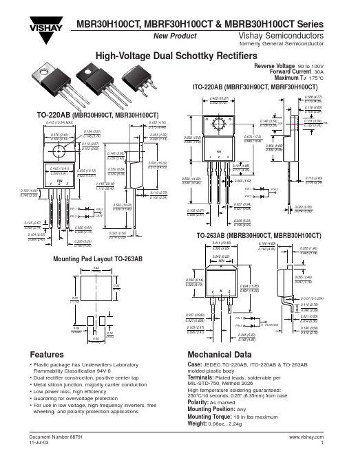
MBR30H100CT , MBRF30H100CT & MBRB30H100CT SeriesVishay Semiconductorsformerly General SemiconductorDocument Number New ProductReverse Voltage 90 to 100VForward Current 30A Maximum T J 175°CMounting Pad Layout TO-263ABITO-220AB (MBRF30H90CT, MBRF30H100CT)(MBR30H90CT, MBR30H100CT)TO-263AB (MBRB30H90CT, MBRB30H100CT)Features• Plastic package has Underwriters Laboratory Flammability Classification 94V-0• Dual rectifier construction, positive center tap • Metal silicon junction, majority carrier conduction • Low power loss, high efficiency• Guardring for overvoltage protection• For use in low voltage, high frequency inverters, free wheeling, and polarity protection applicationsMechanical DataCase:JEDEC TO-220AB, ITO-220AB & TO-263AB molded plastic bodyTerminals:Plated leads, solderable per MIL-STD-750, Method 2026High temperature soldering guaranteed: 250°C/10 seconds, 0.25" (6.35mm) from case Polarity:As markedMounting Position: AnyMounting Torque:10 in-lbs maximum Weight:0.08oz., 2.24gMBR30H100CT , MBRF30H100CT & MBRB30H100CT SeriesVishay Semiconductorsformerly General Semiconductor Document Number 88791Maximum Ratings (TC= 25°C unless otherwise noted)ParameterSymbol MBR30H90CTMBR30H100CTUnit Maximum repetitive peak reverse voltage V RRM 90100V Working peak reverse voltage V RWM 90100V Maximum DC blocking voltageV DC 90100V Maximum average forward rectified current Total device 30(see fig. 1)Per leg I F(AV)15A Peak forward surge current8.3ms single half sine-wave superimposed I FSM 275A on rated load (JEDEC Method) per legPeak repetitive reverse current per leg at t p = 2µs, 1KH Z I RRM 1.0A Voltage rate of change (rated V R )dv/dt 10,000V/µs Operating junction and storage temperature range T J , T STG –65 to +175°C RMS Isolation voltage (MBRF type only) from terminals 4500(1)to heatsink with t = 1 second, RH ≤30%V ISOL3500(2)V1500(3)Electrical Characteristics (TC= 25°C unless otherwise noted)ParameterSymbolValue Unit at I F = 15A, T J = 25°C 0.82Maximum instantaneous at I F = 15A, T J = 125°C V F0.67Vforward voltage per leg (4)at I F = 30A, T J = 25°C 0.93at I F = 30A, T J = 125°C0.80Maximum reverse current per leg T J = 25°C 5.0µA at working peak reverse voltage (4)T J = 125°CI R6.0mAThermal Characteristics (TC= 25°C unless otherwise noted)ParameterSymbol MBR MBRF MBRB UnitTypical thermal resistance per legR θJC1.94.61.9OC/WNotes:(1) Clip mounting (on case), where lead does not overlap heatsink with 0.110” offset (2) Clip mounting (on case), where leads do overlap heatsink(3) Screw mounting with 4-40 screw, where washer diameter is ≤ 4.9 mm (0.19”)(4) Pulse test: 300µs pulse width, 1% duty cycleOrdering InformationProductCase Package CodePackage OptionMBR30H90CT - MBR30H100CT TO-220AB 45Anti-Static tube, 50/tube, 2K/carton MBRF30H90CT - MBRF30H100CT ITO-220AB 45Anti-Static tube, 50/tube, 2K/carton 3113” reel, 800/reel, 4.8K/cartonMBRB30H90CT - MBRB30H100CTTO-263AB45Anti-Static tube, 50/tube, 2K/carton81Anti-Static 13” reel, 800/reel, 4.8K/cartonMBR30H100CT , MBRF30H100CT & MBRB30H100CT SeriesVishay Semiconductorsformerly General SemiconductorDocument Number Ratings andCharacteristic Curves (T A = 25°C unless otherwise noted)100100.10.011.0J u n c t i o n C a p a c i t a n c e (p F )110100100100000.110Reverse Voltage (V)t, Pulse Duration (sec.)I F -- I n s t a n t a n e o u s F o r w a r d C u r r e n t (A )5101520253035Fig. 1 – Forward Derating CurvePer LegA v e r a g e F o r w a r d C u r r e n t (A )Fig. 2 – Maximum Non-Repetitive Peak Forward Surge Current Per Leg1000。
厌氧酸化SBR法处理甲醛废水
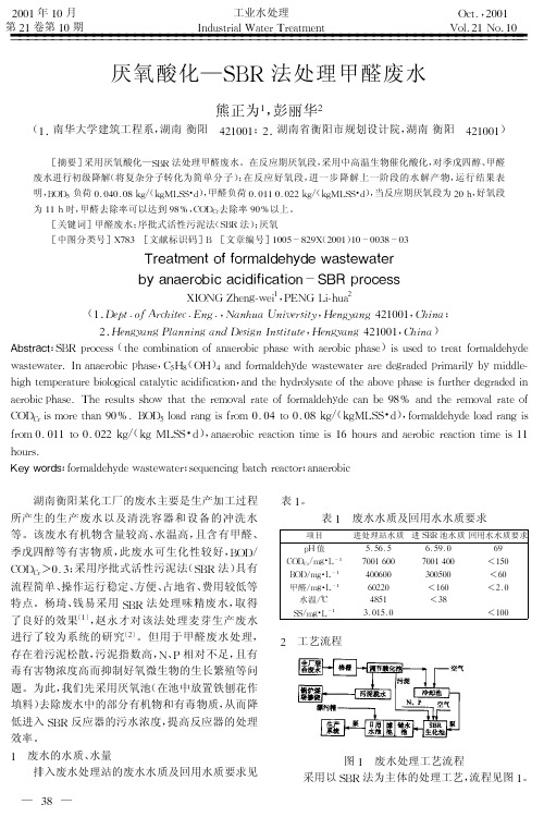
存在着污泥松散, 污泥指数高, 且有 N、 P 相对不足, 毒有害物浓度高而抑制好氧微生物的生长繁殖等问 题。为此, 我们先采用厌氧池 (在池中放置铁刨花作 填料) 去除废水中的部分有机物和有毒物质, 从而降 低进入 SBR 反应器的污水浓度, 提高反应器的处理 效率。 1 废水的水质、 水量 排入废水处理站的废水水质及回用水质要求见 — 38 —
建构筑物名称 格栅池 调节池
物, 并兼作沉淀池使用。 ( 调节酸化池: 此构筑物设于 SBR 生化池下 2) 面, 内放置有铁刨花填料, 由于进水呈弱酸性, 生成 部分亚铁盐, 以改善 SBR 生化池内污泥的沉降性 能, 同时调节水质。废水在此经过近一天的停留后, 大分子有机物 (季戊四醇) 被厌氧菌分解成有机小分 子, 有毒有害物质 (甲醇) 被厌氧菌部分分解, 减轻了 后续处理的难度。 ( 甲醛废水是比较复杂的有机 3) SBR 生化池: 废水, 除有一定浓度的 CODCr 、 BOD5 值和较高的可 生化性 (BOD5/ 外, 其废水中 SS 浓度 CODCr !0 .3 ) 较低, 并含有毒有害物质, 为 N、 P 含量较低。因此, 去除较高浓度的甲醛物质, 除适当增加 N 、 P 营养元 素外, 要提高 DO 浓度, 并控制在 2 !4 mg/ 以提 L, 高活性污泥的活性。在停止曝气进入沉淀阶段, 当 有利于丝状菌生长, 造成污泥颗粒 DO 浓度偏高时, 较松, 沉降性能不好。因此, 在反应中适当投加絮凝 剂硫酸亚铁 (投加量 8l4 mg/ , 以改善沉降性能, L) 同时也可在整个反应过程中抑制污泥膨胀现象。 4 运行程序与处理结果 本 活 性 污 泥 采 用 接 种 培 菌, 完 成 驯 化 过 程。
厌氧酸化—SBR 法处理甲醛废水
熊正为1 , 彭丽华2
塑料缩写对照表

塑料缩写对照表
中文名称
丙烯酸甲酯 甲基丙烯酸 甲基丙烯酸甲酯-丙烯腈-丁二烯-苯乙烯共聚物 甲基丙烯醛 甲基丙烯酸-丁二烯-苯乙烯共聚物 甲基纤维素 三聚氰胺氰脲酸盐 改性聚己内酰胺(铸型尼龙6) 改性氯丁冷粘鞋用胶 二苯甲烷二异氰酸酯(甲撑二苯基二异氰酸酯) 中密聚乙烯 丁酮(甲乙酮) 过氧化甲乙酮 酯肪酸甲酯磺酸盐 三聚氰胺-甲醛树脂 改性高冲聚苯乙烯 甲基异丁基酮 甲基丙烯酸甲酯 甲基甲酰胺 甲基丙烯腈 乙醇酸乙酯 三聚氨胺-酚醛树脂 甲基丙基甲酮 改性聚丙烯 改性聚苯醚 改性聚苯乙烯 苯乙烯-甲基丙烯酸甲酯树脂 石油醚 甲基叔丁基醚 氯丁胶新型交联剂 旋转模塑 醇溶三元共聚尼龙 间苯二甲基二胺 丁腈橡胶 二异氰酸萘酯 邻苯二甲酸正癸辛酯 邻苯二甲酸己正癸酯 偏苯三酸正己酯 癸二酸二异辛酯 正硬酯酸铅 N-甲基吡咯烷酮 己二酸正辛正癸酯 邻苯二甲酸正辛正癸酯 壬基酚聚氧乙烯醚 天然橡胶
塑料缩写对照表
中文名称
异辛醇 丙烯酸 丙烯酸酯-丙烯酸酯-苯乙烯共聚物 丙烯腈/丁二烯/丙烯酸酯共聚物 偶氮(二)甲酰胺 壬基苯氧基丙烷磺酸钠 丙烯腈/丁二烯/苯乙烯共聚物 偶氮(二)异丁腈 丙烯腈/甲基丙烯酸甲酯共聚物 聚芳香酯 丙烯腈-苯乙烯树脂 丙烯腈/苯乙烯/丙烯酸酯共聚物 苯甲醇 正丁醛苯胺缩合物 碱式氯化铝 新型阻燃剂 双水杨酸双酚A酯 2,3-巯(基)丙醇 邻苯二甲酸丁苄酯 N-叔丁基-乙-苯并噻唑次磺酰胺 叶酸 β -环糊精 苯顺二醇 氯化亚硝脲 丁二烯 丙烯酸乳胶外墙涂料 苯偶姻乙醚 硼纤维增强塑料 丁二醇 反应性稀释剂 特丁基-4羟基茴香醚 二丁基羟基甲苯 丁内酯 丙酮-二苯胺高温缩合物 粉末涂料流平剂 甲基丙烯酸丁酯 团状模塑料 氨基树脂皮革鞣剂 氮化硼 新型环氧树脂 β -萘磺酸甲醛低缩合物 己二酸辛苄酯 邻苯二甲酸丁辛酯 双向拉伸(双轴取向)聚丙烯 双酚A
MBR3045PT中文资料
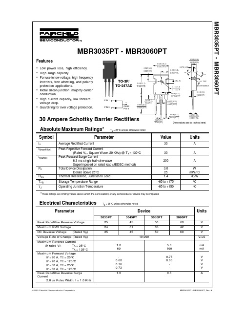
MBR3035PT - MBR3060PTMBR3035PT - MBR3060PT, Rev. A©1999 Fairchild Semiconductor CorporationTO-3P/TO-247ADMBR3035PT - MBR3060PT, Rev. ATRADEMARKSACEx™CoolFET™CROSSVOLT™E 2CMOS TM FACT™FACT Quiet Series™FAST ®FASTr™GTO™HiSeC™The following are registered and unregistered trademarks Fairchild Semiconductor owns or is authorized to use and is not intended to be an exhaustive list of all such trademarks.LIFE SUPPORT POLICYFAIRCHILD’S PRODUCTS ARE NOT AUTHORIZED FOR USE AS CRITICAL COMPONENTS IN LIFE SUPPORTDEVICES OR SYSTEMS WITHOUT THE EXPRESS WRITTEN APPROV AL OF FAIRCHILD SEMICONDUCTOR CORPORA TION.As used herein:ISOPLANAR™MICROWIRE™POP™PowerTrench™QS™Quiet Series™SuperSOT™-3SuperSOT™-6SuperSOT™-8TinyLogic™1. Life support devices or systems are devices or systems which, (a) are intended for surgical implant intothe body, or (b) support or sustain life, or (c) whosefailure to perform when properly used in accordancewith instructions for use provided in the labeling, can be reasonably expected to result in significant injury to the user.2. A critical component is any component of a lifesupport device or system whose failure to perform can be reasonably expected to cause the failure of the life support device or system, or to affect its safety or effectiveness.PRODUCT STATUS DEFINITIONS Definition of TermsDatasheet Identification Product Status Definition Advance InformationPreliminary No Identification Needed Obsolete This datasheet contains the design specifications for product development. Specifications may change in any manner without notice.This datasheet contains preliminary data, andsupplementary data will be published at a later date.Fairchild Semiconductor reserves the right to make changes at any time without notice in order to improve design.This datasheet contains final specifications. Fairchild Semiconductor reserves the right to make changes at any time without notice in order to improve design.This datasheet contains specifications on a product that has been discontinued by Fairchild semiconductor.The datasheet is printed for reference information only.Formative or In DesignFirst ProductionFull ProductionNot In ProductionDISCLAIMERFAIRCHILD SEMICONDUCTOR RESERVES THE RIGHT TO MAKE CHANGES WITHOUT FURTHER NOTICE TO ANY PRODUCTS HEREIN TO IMPROVE RELIABILITY , FUNCTION OR DESIGN. FAIRCHILD DOES NOT ASSUME ANY LIABILITY ARISING OUT OF THE APPLICATION OR USE OF ANY PRODUCT OR CIRCUIT DESCRIBED HEREIN; NEITHER DOES IT CONVEY ANY LICENSE UNDER ITS PATENT RIGHTS, NOR THE RIGHTS OF OTHERS.。
上海尼润粘度计说明书
NDJ系列粘度计是采用高细分驱动步进电机、16位微电脑处理器为核心的、数字式液晶带蓝色背光功能的数显粘度计。
仪器转速平稳、精确,按键标示明确,操作简便,程序化设计。
当扭矩低于20%(或10%)(以仪器报警界限为准)高于90%测量仪器会发出报警声。
屏幕直接显示粘度、转速、百分计标度、转子号以及所选用转子在当前转速下可测的最大粘度值。
主控板、细分驱动板全部采用贴片技术,电路设计采用目前最先进微电脑处理器,结构布局合理紧凑。
提供RS232接口,打印间隔可由用户自行设置。
该仪器满量程、各档线性度全部通过PC接口进行计量校正,其性能、功能达到国外同类型先进水平。
SNB系列粘度计是基于NDJ系列粘度计的升级产品。
除具备NDJ系列粘度计的性能、特点外,SNB系列粘度计的测量范围更广;转速选择改为全程无级变速;配置RTD温度探头实时监测粘度温度,精度可达0.1℃,温度测量范围为0℃-120℃;选配SNB数据采集和绘图软件通过PC接口进行全自动化数据采集,数据保存及历史数据对比等多项数理统计分析任务。
DV系列数字式粘度测量仪是世界上最通用粘度测量仪。
该仪器价廉物美深受客户欢迎,其功能、性能达到国外同类型产品先进水平。
除具备SNB系列粘度计的性能、特点外,还可进行精确剪切速率、剪切应力测量。
双向RS232接口,可与电脑通讯,实现程控和数据采集。
选购DV程控脱机下载软件将自定义的测量程序下载到仪器上实现自动化操作和个性化操作。
选购DV数据采集和程控分析软件实现电脑全自动化采集和分析流体流变特性曲线,另可实现数据保存,历史数据对比等功能。
NDJ系列、SNB系列、DV系列粘度计用于测量液体的粘性阻力即液体的动力粘度。
广泛应用于测定油脂、油漆、油墨、食品、涂料、造纸、化妆品、化工、胶囊、胶粘剂、胶水、精密陶瓷、树脂、牙膏、锂电池浆料及药物等各种流体的粘度。
1. 各仪器主要技术指标NDJ系列主要技术规格配小量样品适配器各系列量程SNB系列量程DV系列主要技术规格2. 数字式粘度计结构原理如图所示,以高细分驱动步进电机带动传感器指针,通过游丝和转轴带动转子旋转。
短程硝化工艺预处理合成革废水的研究

短程硝化工艺预处理合成革废水的研究胡家朋【摘要】针对合成革废水的生物脱氮工艺主要围绕缩短硝化反硝化的流程进行探求经济高效的合成革废水脱氮新技术,采用短程硝化(PNP)工艺预处理合成革废水,通过控制系统温度为(33±1)℃,初始游离氨(FA)为10~35 mg/L,溶解氧约0.2~0.6 mg/L,pH值约7.5~8.3,30 d内实现了实际合成革废水(COD 160~580mg/L,NH4+-N 260~460 mg/L)短程硝化的成功启动.研究结果表明:出水NO2--N浓度约为200~300 mg/L,NO3--N浓度稳定地保持在5 mg/L以下,亚硝酸盐积累率达95%以上.【期刊名称】《武夷学院学报》【年(卷),期】2017(036)006【总页数】6页(P1-6)【关键词】合成革废水;短程硝化;生物脱氮;工艺优化【作者】胡家朋【作者单位】福建省生态产业绿色技术重点实验室(武夷学院),福建武夷山354300;武夷学院生态与资源工程学院,福建武夷山 354300【正文语种】中文【中图分类】X703.1厌氧氨氧化(anammox)工艺所必需的基质主要是NH4+-N和NO2--N。
其中NH4+-N在实际废水中普遍存在,属于需要降解的基本污染物;而NO2--N属于硝化过程的中间产物,在实际废水中基本不存在。
因而,为了实现厌氧氨氧化反应的顺利进行,向反应器提供稳定的NO2--N就成为了一种必不可少的步骤[1-3]。
为此,引入短程硝化工艺作为厌氧氨氧化的前置工艺,力求在氨氧化阶段实现约一半的NH4+-N氧化成NO2--N,即实现半亚硝化。
由此,如何长期稳定地维持高浓度的NO2--N的积累,就成为短程硝化工艺研究的重点。
短程硝化工艺的启动的原理是利用亚硝酸菌(AOB)和硝酸菌(NOB)在生理机制和动力学特性上存在的特有差异,控制反应条件,逐渐淘汰NOB,富集AOB,进而使硝化反应停留在亚硝化阶段。
SBR活性污泥吸附水中重金属离子的研究

SBR活性污泥吸附水中重金属离子的研究吴云海;胡玥;谢正威【摘要】研究了SBR活性污泥对重金属离子(Cu2+、Zn2+、Mn2+、Fe3+)的吸附作用.结果表明:在30℃温度下,pH为5时,其对Cu2+、Zn2+、Mn2+的去除率达到最大值50%左右;当pH为3时,对Fe3+的去除率达到最大值73.6%.吸附动力学过程可用二级吸附速率方程描述.在10~30℃温度范围内,随着温度的升高,Cu2+、Zn2+、Mn2+、Fe3+的去除率分别由54.6%、46.3%、45.3%、68.9%,增大到58.6%、51.3%、49.6%、73.6%.当重金属离子初始质量浓度为50-mg/L,污泥投加量为0.2-g时,Cu2+、Zn2+、Mn2+和Fe3+的去除率达到最大值,分别为61.5%、54.3%、53.3%和76.2%.吸附等温线结果表明,Cu2+、Zn2+、Mn2+、Fe3+在吸附剂上的吸附可用Freundlich方程描述.【期刊名称】《水资源保护》【年(卷),期】2010(026)005【总页数】4页(P71-74)【关键词】SBR活性污泥;重金属;吸附等温线;动力学【作者】吴云海;胡玥;谢正威【作者单位】河海大学环境学院,江苏,南京,210098;河海大学环境学院,江苏,南京,210098;河海大学环境学院,江苏,南京,210098【正文语种】中文【中图分类】X703目前,重金属对水体的污染已成为重要的环境问题之一。
传统的治理方法有离子交换法、化学沉淀法、膜方法(反渗析、电渗析、超滤)、活性炭吸附法等,由于成本比较高、低浓度条件下的去除效果比较差、处置困难、易产生二次污染等原因而使其应用受到限制[1-2],而生物吸附方法是目前研究的热点之一,它具有成本低廉、高效的优点。
根据实际情况选择廉价高效的吸附剂,对于经济地处理含重金属离子的废水具有重要意义。
序批式活性污泥法工艺(简称SBR工艺)运行方式灵活,可以实现厌氧/缺氧/好氧的交替运行,这种交替变化的环境条件常可获得沉降性能好的活性污泥,成本低,且方便可取。
SBR3045SCTB;中文规格书,Datasheet资料

30A SBRSUPER BARRIER RECTIFIERFeatures• Designed as Bypass Diodes for Solar Panels• Selectively Rated for 200ºC Maximum Junction Temperature for High Thermal Reliability.• Patented Super Barrier Rectifier Technology • Soft, Fast Switching Capability• 175ºC Operating Junction Temperature• Lead Free Finish, RoHS Compliant (Note 1)• Also Available in Green Molding Compound (Note 2)Mechanical Data• Case: D 2Pak • Case Material: Molded Plastic, UL Flammability ClassificationRating 94V-0 • Terminals: Matte Tin Finish annealed over Copper leadframe.Solderable per MIL-STD-202, Method 208 • Weight: 1.6 grams (approximate)Ordering Information (Notes 2 & 3)Part Number Case PackagingSBR3045SCTB D 2Pak 50pieces/tubeSBR3045SCTB-G D 2Pak 50 pieces/tubeSBR3045SCTB-13 D 2Pak 800/Tape & ReelSBR3045SCTB-13-G D 2Pak 800/Tape & ReelNotes:1. EU Directive 2002/95/EC (RoHS). All applicable RoHS exemptions applied, see EU Directive 2002/95/EC Annex Notes2. For Green Molding Compound version part numbers, add "-G" suffix to part number above. Examples: SBR3045SCTB-G.3. For packaging details, go to our website at .Marking InformationTop View Package Pin-Out ConfigurationSBR3045SCTB = Product Type Marking Code AB = Foundry and Assembly Code YYWW = Date Code MarkingYY = Last two digits of year (ex: 08 = 2008) WW = Week (01 - 53)Maximum Ratings (Per Leg) @T A = 25°C unless otherwise specifiedSingle phase, half wave, 60Hz, resistive or inductive load. For capacitance load, derate current by 20%.Characteristic Symbol Value UnitPeak Repetitive Reverse VoltageWorking Peak Reverse Voltage DC Blocking Voltage V RRM V RWM V RM 45 V Average Rectified Output Current (Per Leg) (Total) I O1530 A Non-Repetitive Peak Forward Surge Current 8.3msSingle Half Sine-Wave Superimposed on Rated Load I FSM220 AThermal Characteristics (Per Leg)Characteristic Symbol Value UnitTypical Thermal Resistance Junction to Case R θJC2 ºC/W Operating Temperature Range V R ≤ 80% V RRMT J -65 to +175 ºC V R ≤ 50% V RRM≤180 DC Forward Mode ≤200Storage Temperature Range T STG -65 to +175 ºCElectrical Characteristics (Per Leg) @T A = 25°C unless otherwise specifiedCharacteristic Symbol Min Typ Max Unit Test ConditionForward Voltage Drop V F- - - - 0.650.58 V I F = 15A, T J = 25ºC I F = 15A, T J = 125ºCLeakage Current (Note 4) I R- - 0.03 10 0.240 mA V R = 45V, T J = 25ºC V R = 45V, T J = 125ºCNotes:4. Short duration pulse test used to minimize self-heating effect.Fig.1 Typical Forward CharacteristicsV , INSTANTANEOUS FORWARD VOLTAGE (mV)F I , I N S T A N T A N E O U S F O R W A R D C U R R E N T (A )FFig. 2 Typical Reverse CharacteristicsV , INSTANTANEOUS REVERSE VOLTAGE (V)R I , I N S T A N T A N E O U S R E V E R S E C U R R E N T (µA )RI A V E R A G E F O R W A R D C U R R E N T (A )F (A V ),T , CASE TEMPERATURE (C)Fig. 3 Forward Current Derating Curve C °Package Outline DimensionsSuggested Pad LayoutD 2PAKDim Min Max A 4.07 4.82 b 0.51 0.99 b1 1.15 1.77 c 0.356 0.58 c1 1.143 1.65 D 8.39 9.65 D1 6.55 ⎯ E 9.66 10.66 E1 6.23 ⎯ e 2.54 Typ H 14.61 15.87 L 1.78 2.79 L1 ⎯ 1.67 L2 ⎯ 1.77 a 0° 8°All Dimensions in mmDimensionsValue (in mm)Z 16.9 X1 1.1 X2 10.8 Y1 3.5 Y2 7.01 E1 2.5X2ZX1Y1E1Y2IMPORTANT NOTICEDIODES INCORPORATED MAKES NO WARRANTY OF ANY KIND, EXPRESS OR IMPLIED, WITH REGARDS TO THIS DOCUMENT, INCLUDING, BUT NOT LIMITED TO, THE IMPLIED WARRANTIES OF MERCHANTABILITY AND FITNESS FOR A PARTICULAR PURPOSE (AND THEIR EQUIVALENTS UNDER THE LAWS OF ANY JURISDICTION).Diodes Incorporated and its subsidiaries reserve the right to make modifications, enhancements, improvements, corrections or other changes without further notice to this document and any product described herein. Diodes Incorporated does not assume any liability arising out of the application or use of this document or any product described herein; neither does Diodes Incorporated convey any license under its patent or trademark rights, nor the rights of others. Any Customer or user of this document or products described herein in such applications shall assume all risks of such use and will agree to hold Diodes Incorporated and all the companies whose products are represented on Diodes Incorporated website, harmless against all damages.Diodes Incorporated does not warrant or accept any liability whatsoever in respect of any products purchased through unauthorized sales channel. Should Customers purchase or use Diodes Incorporated products for any unintended or unauthorized application, Customers shall indemnify and hold Diodes Incorporated and its representatives harmless against all claims, damages, expenses, and attorney fees arising out of, directly or indirectly, any claim of personal injury or death associated with such unintended or unauthorized application.Products described herein may be covered by one or more United States, international or foreign patents pending. Product names and markings noted herein may also be covered by one or more United States, international or foreign trademarks.LIFE SUPPORTDiodes Incorporated products are specifically not authorized for use as critical components in life support devices or systems without the express written approval of the Chief Executive Officer of Diodes Incorporated. As used herein:A. Life support devices or systems are devices or systems which:1. are intended to implant into the body, or2. support or sustain life and whose failure to perform when properly used in accordance with instructions for use provided in thelabeling can be reasonably expected to result in significant injury to the user.B. A critical component is any component in a life support device or system whose failure to perform can be reasonably expected to cause the failure of the life support device or to affect its safety or effectiveness.Customers represent that they have all necessary expertise in the safety and regulatory ramifications of their life support devices or systems, and acknowledge and agree that they are solely responsible for all legal, regulatory and safety-related requirements concerning their products and any use of Diodes Incorporated products in such safety-critical, life support devices or systems, notwithstanding any devices- or systems-related information or support that may be provided by Diodes Incorporated. Further, Customers must fully indemnify Diodes Incorporated and its representatives against any damages arising out of the use of Diodes Incorporated products in such safety-critical, life support devices or systems.Copyright © 2011, Diodes Incorporated分销商库存信息: DIODESSBR3045SCTB。
SBR1030中文资料

Maximum Ratings and Electrical CharacteristicsNotes:(1) Pulse test: 300¥ìS pulse width, 1% duty cycle(2) Thermal resistance from junction to case(Ratings at 25¡É ambient temperature unless otherwise specified, single phase, half wave, resistive or inductive load. For capacitive load, derate by 20%)FeaturesMechanical Data· Plastic Package has Underwriters LaboratoryFlammability Classification 94V-0· Metal silicon junction, majority carrier conduction · Guard ring for overvoltage protection · Low power loss, high efficiency· High current capability, Low forward voltage drop · Single rectifier construction · High surge capability· For use in low voltage, high frequency inverters, free wheeling, and polarity protection applications · High temperature soldering guaranteed : 250¡É/10 seconds, 0.25" (6.35mm) from case· Case : JEDEC TO-220 molded plastic body · Terminals : Lead solderable perMIL-STD-750, Method 2026· Polarity : As marked · Mounting Position : Any· Weight : 0.08ounce, 2.24 gramsSymbolsSBR1020SBR1040Units Maximum repetitive peak reverse voltage V RRM 203040Volts Maximum RMS voltage V RMS 0.70Maximum DC blocking VoltageV DC Volts Maximum average forward rectified current (see Fig. 1)I(AV )10.0Peak forward surge current 8.3ms single half sine-wave superimposed on rated load (JEDEC method)150.0AmpsMaximum instantaneous forward voltage at 10A (Note 1)V F 1.0Volts T A =25¡ÉMaximum instantaneous reverse current at rated DC blocking voltage (Note1)T A =125¡ÉmA Typical thermal resistance (Note 2)¡É/W Operating junction temperature range ¡ÉI R I FSMT JVolts SBR1030142128203040Repetitive peak forward current(square wavr,20KHZ) at Tc=105¡ÉStorage temperature rangeT STG-65 to +150-65 to +150¡ÉSBR10505060SBR106035425060R¥èJC 2.53020.0Amps Amps I FRM0.80Dimensions in inches and (millimeters)TO-220A.200(5.08)Case Positive.120PIN 2Suffix "R"FIG.1-FORWARD CURRENT DERATING CURVEA V E R A G E F O R W A R D C U R R E N T A M P E R E SLEAD TEMPERATURE (¡É)06842101215010060804020120I N S T A N T A N E O U S F O R W A R D C U R R E N T (A M P E R E S )INSTANTANEOUS FORWARD VOLTAGE (VOLTS)0.01501010.10.1 1.21.00.80.60.20.5 1.10.90.70.30.4REVERSE VOLTAGE. VOLTSJ U N C T I O N C A PA C I T A N C E (p F )0.1100101FIG.5-TYPICAL JUNCTION CAPACITANCE40001000100FIG.2-MAXIMUM NON-REPETITIVE PEAKFORWARD SURGE CURRENTP E A K F O R W A R D S U R G E C U R R E N T (A M P E R E S )NUMBER OF CYCLES AT 60Hz2512510075501501751100100.1FIG.4-TYPICAL REVERSE CHARACTERISTICSPERCENT OF RATED PEAK REVERSE VOLTAGE (%)I N S T A N T A N E O U S R E V E R S E C U R R E N T M I L L (A M P E R E S )0.0011010.10.0120FIG.6-TYPICAL TRANSIENT THERMAL IMPEDANCET, PULSE DURATION, sec.T R AN S I E N T T H E R M A L I M P E D A N C E ,¡É/ W0.011001010.11100100.1FIG.3-TYPICAL INSTANTANEOUS FORWARD CHARACTERISTICS。
第四组:请为最低-60℃使用橡胶制品的生产选择合适的高分子材料

2)取代基
旁侧基团的极性,对分子链的内旋转和分子间的相互作用都会产生很大的影响.侧基 的极性越强,Tg越高. 烯烃高聚物取代基的极性和Tg的关系。此外,增加分子链上极 性基团的数量,也能提高高聚物的Tg.但当极性基团的数量超过一定值后,由于它们之 间的静电斥力超过吸引力,反而导致分子链间距离增大,Tg下降.取代基的位阻增加, 分子链内旋转受阻碍程度增加,Tg升高.应当强调指出,侧基的存在并不总是使Tg增大 的.取代基在主链上的对称性对Tg也有很大影响,聚偏二氯乙烯中极性取代基对称双 取代,偶极抵销一部分,整个分子极性矩减小,内旋转位垒降低,柔性增加,其Tg比聚氯 乙烯为低;而聚异丁烯的每个链节上, 有两个对称的侧甲基,使主链间距离增大,链间 作用力减弱,内旋转位垒降低,柔性增加,其Tg比聚丙烯为低.又如,当高聚物中存在柔 性侧基时,随着侧基的增大,在一定范围内,由于柔性侧基使分子间距离加大,相互作 用减弱,即产生"内增塑"作用,所以,Tg反而下降.
2、其他结构因素的影响
1) 共聚 无规共聚物的Tg介于两种共聚组分单体的Tg之间,并且随着共聚组分的变化,其Tg在 两种均聚物的Tg之间线性或非线性变化.非无规共聚物中,最简单的是交替共聚,他们 可以看成是两种单体组成一个重复单元的均聚物,因此只有一个Tg.而嵌段或接枝共 聚物情况就复杂多了. 2)交联 随着交联点的增加,高聚物自由体积减少,分子链的运动受到约束的程度也增加,相邻 交联点之间平均链长变小,所以Tg升高. 3)分子量 分子量的增加使Tg增加,特别是在分子量很小时,这种影响明显,当分子量超过一定的 程度后,Tg随分子量变化就不明显了. 4)增塑剂和稀释剂 增塑剂对Tg的影响也是相当显著的,玻璃化温度较高的聚合物在加入增塑剂后,可以 使Tg明显下降.例如:纯的聚氯乙烯Tg=78℃,在室温下是硬塑料,加入45%的增塑剂 后,Tg=-30℃,可以作为橡胶代用品.淀粉的玻璃化温度在加水前后就有明显的变化.
SBR10200CTL-13;中文规格书,Datasheet资料
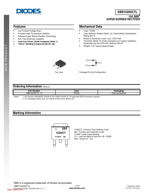
SBR is a registered trademark of Diodes Incorporated 10A SBRSUPER BARRIER RECTIFIERFeatures• Low Forward Voltage Drop• Excellent High Temperature Stability• Patented Super Barrier Rectifier Technology • Soft, Fast Switching Capability• Lead Free Finish, RoHS Compliant (Note 1) • “Green” Molding Compound (No Br, Sb)Mechanical Data• Case: TO252 • Case Material: Molded Plastic, UL Flammability ClassificationRating 94V-0 • Moisture Sensitivity: Level 1 per J-STD-020 • Terminals: Matte Tin Finish annealed over Copper leadframe.Solderable per MIL-STD-202, Method 208 • Weight: 0.317 grams (approximate)Ordering Information (Note 2)Part Number Case PackagingSBR10200CTL-13 TO252 2500pieces/reelNotes: 1. EU Directive 2002/95/EC (RoHS) & 2011/65/EU (RoHS 2). All applicable RoHS exemptions applied. 2. For packaging details, go to our website at .Marking InformationTop ViewPackage Pin-Out Configuration10200CT = Product Type Marking Code AB = Foundry and Assembly Code YYWW = Date Code MarkingYY = Last two digits of year (ex: 08 = 2008) WW = Week (01 - 53)YYWW AB10200CTSBRSBR is a registered trademark of Diodes IncorporatedMaximum Ratings (Per Leg) @T A = 25°C unless otherwise specifiedSingle phase, half wave, 60Hz, resistive or inductive load. For capacitance load, derate current by 20%.Characteristic Symbol Value UnitPeak Repetitive Reverse VoltageWorking Peak Reverse Voltage DC Blocking Voltage V RRM V RWMV RM 200 V Average Rectified Output Current Per Device (Per Leg) (Total) I O510 A Non-Repetitive Peak Forward Surge Current 8.3msSingle Half Sine-Wave Superimposed on Rated Load I FSM110 AThermal Characteristics (Per Leg)Characteristic Symbol Value UnitTypical Thermal Resistance (Notes 3) R θJC 2 ºC/W Operating and Storage Temperature Range T J , T STG-65 to 150 ºCElectrical Characteristics (Per Leg) @T A = 25°C unless otherwise specifiedCharacteristic Symbol Min Typ Max Unit TestConditionForward Voltage Drop V F- 0.88 - 0.940.85 V I F = 5A, T J = 25ºC I F = 5A, T J = 125ºCLeakage Current (Note 4) I R- - 100 20 μAmA V R = 200V, T J = 25ºC V R = 200V, T J = 125ºCNotes:3. Device mounted on Polymide substrate, 125mm2 copper pad, double-sided, PC boards.4. Short duration pulse test used to minimize self-heating effect.I AVERAGE FORWARD CURRENT (A)Fig. 1 Forward Power Dissipation F(AV)P , P O W E R D I S S I P A T I O N (W )DFig. 2 Typical Forward CharacteristicsV , INSTANTANEOUS FORWARD VOLTAGE (V)F I , I N S T A N T A N E O U S F O R W A R D C U R R E N T (A )FSBR is a registered trademark of Diodes Incorporated0.010.1110Fig. 3 Typical Reverse CharacteristicsV , INSTANTANEOUS REVERSE VOLTAGE (V)R I , I N S T A N T A N E O U S R E V E R S E C U R R E N T (µA )R Fig. 4 Forward Current Derating CurveT , AMBIENT TEMPERATURE (°C)A I , A V E R A G E F O R W A R D C U R R E N T (A )F (A V )Package Outline DimensionsTO252Dim Min Max Typ A 2.19 2.39 2.29A10.00 0.13 0.08A20.97 1.17 1.07b 0.64 0.88 0.783b20.76 1.14 0.95b3 5.21 5.46 5.33c2 0.45 0.58 0.531D 6.00 6.20 6.10D1 5.21 − − e − − 2.286E 6.45 6.70 6.58E1 4.32 − − H 9.40 10.41 9.91L 1.40 1.78 1.59L3 0.88 1.27 1.08L4 0.64 1.02 0.83a 0° 10° − All Dimensions in mmSBR is a registered trademark of Diodes IncorporatedSuggested Pad LayoutIMPORTANT NOTICEDIODES INCORPORATED MAKES NO WARRANTY OF ANY KIND, EXPRESS OR IMPLIED, WITH REGARDS TO THIS DOCUMENT, INCLUDING, BUT NOT LIMITED TO, THE IMPLIED WARRANTIES OF MERCHANTABILITY AND FITNESS FOR A PARTICULAR PURPOSE (AND THEIR EQUIVALENTS UNDER THE LAWS OF ANY JURISDICTION).Diodes Incorporated and its subsidiaries reserve the right to make modifications, enhancements, improvements, corrections or other changes without further notice to this document and any product described herein. Diodes Incorporated does not assume any liability arising out of the application or use of this document or any product described herein; neither does Diodes Incorporated convey any license under its patent or trademark rights, nor the rights of others. Any Customer or user of this document or products described herein in such applications shall assume all risks of such use and will agree to hold Diodes Incorporated and all the companies whose products are represented on Diodes Incorporated website, harmless against all damages.Diodes Incorporated does not warrant or accept any liability whatsoever in respect of any products purchased through unauthorized sales channel. Should Customers purchase or use Diodes Incorporated products for any unintended or unauthorized application, Customers shall indemnify and hold Diodes Incorporated and its representatives harmless against all claims, damages, expenses, and attorney fees arising out of, directly or indirectly, any claim of personal injury or death associated with such unintended or unauthorized application.Products described herein may be covered by one or more United States, international or foreign patents pending. Product names and markings noted herein may also be covered by one or more United States, international or foreign trademarks.LIFE SUPPORTDiodes Incorporated products are specifically not authorized for use as critical components in life support devices or systems without the express written approval of the Chief Executive Officer of Diodes Incorporated. As used herein:A. Life support devices or systems are devices or systems which: 1. are intended to implant into the body, or2. support or sustain life and whose failure to perform when properly used in accordance with instructions for use provided in thelabeling can be reasonably expected to result in significant injury to the user.B. A critical component is any component in a life support device or system whose failure to perform can be reasonably expected to cause the failure of the life support device or to affect its safety or effectiveness.Customers represent that they have all necessary expertise in the safety and regulatory ramifications of their life support devices or systems, and acknowledge and agree that they are solely responsible for all legal, regulatory and safety-related requirements concerning their products and any use of Diodes Incorporated products in such safety-critical, life support devices or systems, notwithstanding any devices- or systems-related information or support that may be provided by Diodes Incorporated. Further, Customers must fully indemnify Diodes Incorporated and its representatives against any damages arising out of the use of Diodes Incorporated products in such safety-critical, life support devices or systems.Copyright © 2012, Diodes IncorporatedDimensionsValue (in mm)Z 11.6 X1 1.5 X2 7.0 Y1 2.5 Y2 7.0 C 6.9 E1 2.3X2CZX1Y1E1Y2分销商库存信息: DIODESSBR10200CTL-13。
MBR3045中文资料

Maximum Ratings
• •
Operating Temperature: -55°C to +150°C Storage Temperature: -55°C to +150°C Maximum Recurrent Peak Reverse Voltage 20V 30V 35V 40V 45V 60V 80V 100V Maximum DC Blocking Voltage 20V 30V 35V 40V 45V 60V 80V 100V
MBR3020 thru MBR30100
Figure 1 Typical Forward Characteristics 200 100 60 40 25 20 25°C Amps 10 6 4 2 1 .6 .4 .2 .1 0.05 0.06 0.07 Volts Instantaneous Forward Current - Amperes versus Instantaneous Forward Voltage - Volts 0.08 0.09 0.1 0 5 Amps 10 20 30
元器件交易网
MBR3020 thru MBR30100
Figure 4 Typical Reverse Characteristics 1000 600 400 350 200 100 60 40 20 mAmps 10 6 4 2 1 .6 .4 .2 .1 10 20 TA=25°C 40 60 Volts Instantaneous Reverse Leakage Current - MicroAmperes versus Percent Of Rated Peak Reverse Voltage - Volts 80 100 120 TA=125°C 0 1 2 4 Amps 300 250 200 100
SBR3A40SA-13;中文规格书,Datasheet资料

3.0A SBRSUPER BARRIER RECTIFIERSMAFeatures• Low Leakage Current • Patented Super Barrier Rectifier Technology • Soft, Fast Switching Capability • 150ºC Operating Junction Temperature • Lead Free Finish, RoHS Compliant (Note 1) • Green Molding Compound (No Halogen and Antimony)(Note 7)Mechanical Data• Case: SMA • Case Material: Molded Plastic, UL Flammability ClassificationRating 94V-0 • Moisture Sensitivity: Level 1 per J-STD-020D • Terminals: Lead Free Plating (Matte Tin Finish.) Solderableper MIL-STD-202, Method 208 • Polarity Indicator: Cathode Band • Marking Information: See Page 3 • Ordering Information: See Page 3 • Weight: 0.064 grams (approximate)Maximum Ratings @T A = 25°C unless otherwise specifiedSingle phase, half wave, 60Hz, resistive or inductive load. For capacitance load, derate current by 20%.Characteristic Symbol Value UnitPeak Repetitive Reverse VoltageWorking Peak Reverse Voltage DC Blocking Voltage V RRM V RWM V RM40 V Maximum Voltage Rate of Change (Rated V R )dv/dt 10,000 V/μs RMS Reverse Voltage V R(RMS)28 V Average Rectified Output Current (See Figure 1) I O3 A Non-Repetitive Peak Forward Surge Current 8.3msSingle Half Sine-Wave Superimposed on Rated Load I FSM45 AThermal CharacteristicsCharacteristic Symbol Value UnitMaximum Thermal Resistance Thermal Resistance Junction to Soldering (Note 2)Thermal Resistance Junction to Ambient (Note 3)Thermal Resistance Junction to Case (Note 3)R θJS R θJAR θJC 5 124 14.3 ºC/W Power Disspation (Note 3) @ T A = 25 ºC P D 1.2 WOperating and Storage Temperature Range T J , T STG-65 to +150 ºCElectrical Characteristics @T A = 25°C unless otherwise specifiedCharacteristic Symbol Min Typ Max Unit TestConditionReverse Breakdown Voltage (Note 5) V (BR)R 40 - - V I R = 0.4mAForward Voltage Drop V F-- -0.300.330.43 - 0.35 0.38 0.50 0.48 V I F = 0.5A, T J = 25ºC I F = 1.0A, T J = 25ºC I F = 3.0A, T J = 25ºC I F = 3.0A, T J = 125ºCLeakage Current (Note 5) I R - 45 80 9 250 400 40 μAμAmA V R = 5V, T J = 25ºC V R = 40V, T J = 25ºC V R = 40V, T J = 125ºCNotes:1. EU Directive 2002/95/EC (RoHS). All applicable RoHS exemptions applied. Please visit our website at /quality/lead_free.html.2. Theoretical R θJS calculated from the top center of the die straight down to the PCB cathode tab solder junction.3. FR-4 PCB, 2 oz. Copper, minimum recommended pad layout per /datasheets/ap02001.pdf. Top View Bottom ViewGreenFig. 1 Forward Power Dissipation1I , AVERAGE FORWARD CURRENT (A)F(AV)P , P O W E R D I S S I P A T I O N (W )D Fig. 2 Typical Forward CharacteristicsV , INSTANTANEOUS FORWARD VOLTAGE (V)F 1101001,00010,000I , I N S T A N T A N E O U S F O R W A R D C U R R E N T (m A )FFig. 3 Typical Reverse Characteristics100510152025303540V , INSTANTANEOUS REVERSE VOLTAGE (V)R I , I N S T A N T A N E O U S R E V E R S E C U R R E N T (m A )R Fig. 4 Total Capacitance vs. Reverse Voltage V , DC REVERSE VOLTAGE (V)R C , T O T A L C A P A C I T A N C E (p F )T 100Fig. 5 Forward Current Derating Curve0.51.01.52.02.53.03.5T , AMBIENT TEMPERATURE (°C)A I , A V E R A G E F O R W A R D C U R R E N T (A )F (A V )Fig. 6 Operating T emperature DeratingV , DC REVERSE VOLTAGE (V)R T , D E R A T E D A M B I E N T T E M P E R A T U R E (°C )AOrdering Information(Note 8)Part Number Case PackagingSBR3A40SA-13 SMA 5000/Tape & Reel Notes: 8. For packaging details, go to our website at /datasheets/ap02007.pdf.Marking InformationPackage Outline DimensionsSuggested Pad LayoutSMADim Min MaxA 2.29 2.92B 4.00 4.60C 1.27 1.63D 0.15 0.31E 4.80 5.59G 0.050.20H 0.761.52J 2.01 2.30All Dimensions in mmDimensions Value (in mm)Z 6.5G 1.5X 1.7Y 2.5C 4.0SV 4 = Product Type Marking Code= Manufacturers’ code markingYWW = Date Code MarkingY = Last digit of year (ex: 7 for 2007)WW = Week code 01 to 52YWWIMPORTANT NOTICEDIODES INCORPORATED MAKES NO WARRANTY OF ANY KIND, EXPRESS OR IMPLIED, WITH REGARDS TO THIS DOCUMENT, INCLUDING, BUT NOT LIMITED TO, THE IMPLIED WARRANTIES OF MERCHANTABILITY AND FITNESS FOR A PARTICULAR PURPOSE (AND THEIR EQUIVALENTS UNDER THE LAWS OF ANY JURISDICTION).Diodes Incorporated and its subsidiaries reserve the right to make modifications, enhancements, improvements, corrections or other changes without further notice to this document and any product described herein. Diodes Incorporated does not assume any liability arising out of the application or use of this document or any product described herein; neither does Diodes Incorporated convey any license under its patent or trademark rights, nor the rights of others. Any Customer or user of this document or products described herein in such applications shall assume all risks of such use and will agree to hold Diodes Incorporated and all the companies whose products are represented on Diodes Incorporated website, harmless against all damages.Diodes Incorporated does not warrant or accept any liability whatsoever in respect of any products purchased through unauthorized sales channel. Should Customers purchase or use Diodes Incorporated products for any unintended or unauthorized application, Customers shall indemnify and hold Diodes Incorporated and its representatives harmless against all claims, damages, expenses, and attorney fees arising out of, directly or indirectly, any claim of personal injury or death associated with such unintended or unauthorized application.Products described herein may be covered by one or more United States, international or foreign patents pending. Product names and markings noted herein may also be covered by one or more United States, international or foreign trademarks.LIFE SUPPORTDiodes Incorporated products are specifically not authorized for use as critical components in life support devices or systems without the express written approval of the Chief Executive Officer of Diodes Incorporated. As used herein:A. Life support devices or systems are devices or systems which:1. are intended to implant into the body, or2. support or sustain life and whose failure to perform when properly used in accordance with instructions for use provided in thelabeling can be reasonably expected to result in significant injury to the user.B. A critical component is any component in a life support device or system whose failure to perform can be reasonably expected to cause the failure of the life support device or to affect its safety or effectiveness.Customers represent that they have all necessary expertise in the safety and regulatory ramifications of their life support devices or systems, and acknowledge and agree that they are solely responsible for all legal, regulatory and safety-related requirements concerning their products and any use of Diodes Incorporated products in such safety-critical, life support devices or systems, notwithstanding any devices- or systems-related information or support that may be provided by Diodes Incorporated. Further, Customers must fully indemnify Diodes Incorporated and its representatives against any damages arising out of the use of Diodes Incorporated products in such safety-critical, life support devices or systems.Copyright © 2009, Diodes Incorporated分销商库存信息: DIODESSBR3A40SA-13。
横河涡街流量计样本

■ 标准规格
性能规格
被测流体: 液体、气体、蒸汽(避免多相流和粘性流体)
测量流速: 参考表7
精度: 读数的±0.75%(液体) 读数的±1%(气体、蒸汽) 参考表9。 当选择多变量型时,参考P.9。
重复性: 读数的±0.2% 标定:
本流量计出厂前都用水流量进行了标定。 当选择多变量型时用水流量进行温度和流量 标定。
正常工作条件
接液温度范围: -29至260˚C (一般型) -196至100˚C (低温型:选购) -29至450˚C (高温型:选购) 当选择多变量型时,参考P.9。 对于一体型参考图1。
工况压力范围: -0.1MPa (-1 kg/cm2) 至法兰额定值。
环境温度范围: -29 至 85℃ (分离型检测器) -40 至 85℃ (分离型转换器) -29 至 85℃ (一体型,参考图1) -29 至 80℃ (带指示器的一体型,参考图1) -30 至 80℃ (带指示器的分离型转换器)
* PS :流量管的最大允许压力,DN:公称通径
** 请参考关于压力仪表指示97/23/EC的EC指示中附件II中 的表6。
*** DY015和DY025不带PED的CE标识,因为它们不属于 PED下的CE标识。
负载电阻 (Ω)
环境温度 (˚C)
4
85
100
80
85 80
55 50
0
-29
-50
-50 -29 0 50 100
■ 先进的自诊断功能: 可预测并显示应用工况的变化,如较大的管道振动、 流态异常等。
■ 高精度: 读数的±0.75%(液体) (读数的±0.5%:象征精度/不保证) 读数的±1%(气体、蒸汽)
丁苯橡胶
丁苯橡胶行业的生产设备腐蚀与防护学院:化学化工学院专业:化学工程与工艺姓名:学号:丁苯橡胶—简介丁苯橡胶(SBR) 是最大的通用合成橡胶品种,也是最早实现工业化生产的橡胶之一。
它是丁二烯与苯乙烯的无规共聚物。
其物理机构性能,加工性能及制品的使用性能接近于天然橡胶,有些性能如耐磨、耐热、耐老化及硫化速度较天然橡胶更为优良,可与天然橡胶及多种合成橡胶并用,广泛用于轮胎、胶带、胶管、电线电缆、医疗器具及各种橡胶制品的生产等领域。
丁苯橡胶按其合成方法通常分为乳液聚合丁苯橡胶(简称乳聚丁苯橡胶,ESBR)和溶液聚合丁苯橡胶(简称溶聚丁苯橡胶,SSBR),乳聚丁苯橡胶是自由基聚合,自工业化生产以来,己过其鼎盛时期,生产技术成熟,产品质量稳定,品种牌号齐全。
溶聚丁苯橡胶采用阴离子活性聚合,具有分子量分布窄、顺式含量高、耐磨性能优异、滚动阻力小,解决了顺丁橡胶存在的抗湿滑性不好的问题,是轮胎面胶理想的材料。
其发展正处于稳步上升阶段。
产品描述中文名:丁苯橡胶英文名 Emulsion-polymerized styrene butadiene rubber (E-SBR)分子结构:生产方法由丁二烯和苯乙烯在低温下进行自由基乳液聚合而制得。
产品性能常温下为白色固体或透明无悬浮物液体,有微芳香味,是一种性能上更优于工业直链烷基苯的洗涤剂产品原料。
以其为原料衍生的表面活性剂产品,性能优良,生物降解性能好,耐硬水,皮肤感觉柔和,脱脂力小,更适合低温洗涤,在低温仍有卓越的去污能力。
SBR-1500是通用污染型软丁苯橡胶的最典型品种,生胶的粘着性和加工性能均优,硫化胶的耐磨性能、拉伸强度、撕裂强度和耐老化性能较好。
SBR-1502是通用非污染型软丁苯橡胶的最典型品种,其性能与SBR-1500相当,有良好的拉伸强度、耐磨耗和屈挠性能。
SBR -1712是一种填充高芳香烃油的软丁苯橡胶的污染性品种,它具有优良的粘着性、耐磨性和可加工性以及价格便宜等优点。
聚丙烯工艺介绍

工艺2.1工艺设计基础2.1.1 生产能力、产品方案和操作弹性(1)设计能力和操作时间a) 聚合生产能力:20万吨/年(按均聚物考虑)反应器台数:3台(1台预聚合反应器, 2台串联的环管反应器)年操作时间:8000小时b) 挤压造粒:一条生产线设计能力:28吨/小时,按均聚/抗冲产品按MFR<1.0g/10min考虑33吨/小时,按均聚/抗冲产品按MFR≥1.0g/10min考虑35吨/小时,按均聚/抗冲产品按MFR≥70g/10min考虑c) 包装码垛:三条全自动生产线,包装生产线采用轨道可移动式。
每条生产线包装能力:1200袋/小时,每袋25kg。
码垛能力:1400袋/小时,每袋25kg。
d) 产品装运:两种装车方式。
使用槽车装运散状聚丙烯粒料。
使用叉车、托盘方式装运袋式包装聚丙烯粒料。
一周生产7天,每天两班,每班8小时。
(2)产品方案本装置可以生产均聚物(包括高刚性牌号)、无规共聚物和抗冲共聚物(作为预留),产品牌号共103个。
a)均聚物56个牌号其中:挤出热成型:10注塑:12纤维:17BOPP膜:13流延膜:4b)无规共聚物21个牌号(预留)其中:流延和管式膜:6BOPP膜的热封层:3挤出和吹塑:4注塑:5流延膜(Clyrell牌号):3b)高抗冲共聚物26个牌号(预留)其中: 适用于全部应用领域: 23专用TPO牌号:3(3)催化剂主催化剂:ZN-GF2A(生产均聚物)ZN-M1(生产均聚物和无规共聚物)ZN-127L、ZN-101、ZN-104、ZN-126 (生产高刚性、高抗冲等专用牌号)助催化剂:三乙基铝(TEAL)给电子体(Donor C)给电子体(Donor D)(4)装置操作弹性从单体净化单元到干燥单元的操作弹性范围:70-120%反应器操作压力范围:3.4-4.5MPag后续关键设备挤压造粒机组的操作弹性范围:60-140%2.1.2 装置组成(1)装置工段组成见下表:表2-1-1装置工段组成表表2-1-1装置工段组成表2.1.3产品规格(1)产品质量表2-1-2 产品质量指标表* -主要是水,单体含量在3-5ppm范围内。
高温和低温聚合的SBR硫化胶的交联密度、动态力学行为和微观结构的研究
高温和低温聚合的SBR硫化胶的交联密度、动态力学行为和微观结构的研究潘宏丽;杨英【摘要】以硫磺、二硫化巯基苯并噻唑(MBTS)和四甲基二硫化秋兰姆(TMTD)为硫化剂,选用5种不同的硫化体系、制备出高温及低温丁苯橡胶(SBR)硫化胶.通过苯溶胀及应力-应变分析测定了硫化胶的交联密度.利用硫醇-胺化学探测仪,测定了硫磺硫化胶的交联键的类型,研究了硫化胶及生胶(未交联)的动态力学性能和热稳定性.利用拉曼(Raman)光谱测定了丁二烯的微观结构及总不饱和度.讨论了硫化胶的交联密度及交联键类型对其性能的影响.【期刊名称】《世界橡胶工业》【年(卷),期】2012(039)012【总页数】7页(P17-23)【关键词】丁苯橡胶;硫化;交联密度;溶胀;应力-应变;热稳定性;微观结构【作者】潘宏丽;杨英【作者单位】中国石油兰州化工研究中心,甘肃兰州730060;中国石油兰州化工研究中心,甘肃兰州730060【正文语种】中文【中图分类】TQ333.10 前言SВR是合成橡胶中应用最广泛的胶种之一。
因其具有良好的耐龟裂性和耐候性,故主要应用于轮胎工业。
此外,SВR 还有诸多其他工业用途,包括制造薄膜、绝缘电线电缆、黏合剂、橡胶玩具、模压橡胶制品、鞋底、瓶塞、外科手术和卫生用制品等。
SВR 可通过高温或低温乳液聚合制备,分别命名为高温SВR和低温SВR。
后者的交联度低,并具有较低的相对分子质量,其性能优于前者。
在一些特殊应用(如食品容器密封剂)场合,可使用二者的共混物。
SВR 硫化胶采用的是硫磺交联。
硫磺和促进剂的相对用量是影响交联密度的重要因素,进而影响硫化胶的力学性能。
在硫磺硫化体系中,硫化过程中发生许多复杂的反应,导致交联键的类型及其长度呈现多样化。
硫或以侧基,或以环状硫化物键合的形式进入聚合物主链,对其物理、力学和黏弹性能产生显著的影响。
文中主要研究高温及低温聚合的SВR硫化胶的交联情况,以及交联对力学性能和热性能的影响,同时,也分析了交联密度与微观结构的关系。
- 1、下载文档前请自行甄别文档内容的完整性,平台不提供额外的编辑、内容补充、找答案等附加服务。
- 2、"仅部分预览"的文档,不可在线预览部分如存在完整性等问题,可反馈申请退款(可完整预览的文档不适用该条件!)。
- 3、如文档侵犯您的权益,请联系客服反馈,我们会尽快为您处理(人工客服工作时间:9:00-18:30)。
Any changing of specification will not be informed individual
Page 1 of 2
元器件交易网
SBR30150R
Elektronische Bauelemente
VOLTAGE 150V 30 .0AMP Schottky Barrier Rectifiers
RATING AND CHARACTERISTIC CURVES
Typical Forward Current Derating Curve
50
Typical Forward Characteristic
Average Forward Current (A); per Leg
21 18
15
12 9 6 3 0 20 50 100 150
TYPE NUMBER
Maximum Recurrent Peak Reverse Voltage Working Peak Reverse Voltage Maximum DC Blocking Voltage Maximum Average Forward Rectified Current (Per Leg) (Per Device) Peak Forward Surge Current, 8.3 ms single half sine-wave superimposed on rated load (JEDEC method) Maximum Instantaneous Forward Voltage (IF = 15 Amps,TF= 25 C, per leg) Maximum Instantaneous Forward Voltage (IF = 15 Amps,TF= 125 C, per leg) Maximum DC Reverse Current Ta=25 oC at Rated DC Blocking Voltage Typical Junction Capacitance (Note1) Typical Thermal Resistance (Note 2) Voltage Rate Of Chance (Rated VR) Operating Temperature Range Storage Temperature Range
.051 MAX. (1.3) .040 MAX. (1.0) .100 (2.54)
.550 (14.0) .158 (4.0) MIN. MAX. .120 (3.05) PIN 1 PIN 3 + CASE PIN 2
Dimensions in inches and (millimeters)
FEATURES
* Low forward voltage drop * High current capability * High reliability * High surge current capability * Epitaxial construction
.108 (2.75)
.412 (10.5) MAX.
元器件交易网
SBR30150R
Elektronische Bauelemente
VOLTAGE 150V 30 .0AMP Schottky Barrier Rectifiers
RoHS Compliant Product A suffix of "-C" specifies halogen & lead-free TO-220
MAXIMUM RATINGS AND ELECTRICAL CHARACTERISTICS
Rating 25 C ambient temperature unless otherwise specified. Single phase half wave, 60Hz, resistive or inductive load. For capacitive load, derate current by 20%.
Peak Forwad surge Current (A)
0.1
100¢J 0.01
160
Tj=25¢J
8.3mS Single half Sine Wave JEDEC Method
120
75¢J
80
0.001 50¢J
40
25¢J
0 0 10 100
0.0001 10
40
70
100
130
160
Number of Cycles at 60Hz
Junction Capacitance (pF)
Forward Voltage (V)
750
500
250
Typical Reverse Characteristic
1
0Байду номын сангаас0.1
1
10
100
Revise Voltage (%)
125¢J
200
Reverse Current(mA)
Maximum Non- Repetitive Forward Surge Current
o
Ta=125 C
o
pF C/W C C
V/us
1. Measured at 1MHz and applied reverse voltage of 5.0V D.C. 2. Thermal Resistance Junction to Case.
01-Jun-2006 Rev. A
NOTES:
SYMBOL VRRM VRSM VDC IF IFSM VF IR CJ RθJA dv/dt TJ TSTG
SBR30150RF 150 150 150 15 30 180 0.87 0.76 0.03 5 350 2.5 10000 -50 ~ +150 -65 ~ +175
UNITS V V V A A V mA
Reverse Voltage(V)
Any changing of specification will not be informed individua
l
01-Jun-2006 Rev. A
Page 2 of 2
3.8 f +.2 HOLE THRU .248 (6.3)
.180 (4.6)
.050 (1.27)
.595 (15.1) MAX.
MECHANICAL DATA
* Case: Molded plastic * Epoxy: UL 94V-0 rate flame retardant * Lead: Lead solderable per MIL-STD-202, method 208 guaranteed * Polarity: As Marked * Mounting position: Any * Weight: 2.24 grams(Approximately)
Instantaneous Forward Current (A)
5
3
125¢J
100¢J 1
75¢J
190
Tc, Case Temperature (¢J)
50¢J
25¢J
Typical Junction Capacitance
1000
0.1 0.3 0.4 0.5 0.6 0.7 0.8 0.9
