BFQ67-GS08中文资料
天诚通信-铜产品
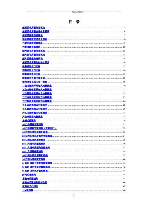
目录超五类非屏蔽信息模块 (5)超五类非屏蔽直通信息模块 (6)超五类屏蔽信息模块 (7)超五类屏蔽直通信息模块 (8)六类非屏蔽信息模块 (9)六类屏蔽信息模块 (10)超六类非屏蔽信息模块 (11)超六类非屏蔽信息模块 (12)超六类屏蔽信息模块 (13)超五类非屏蔽免打线水晶头 (14)经典系列平口面板 (15)雅典系列平口面板 (16)雅典系列斜口面板 (17)雅典系列有线电视面板 (18)数据语音电视三合一面板 (19)二位方形光纤开起式地脚插座 (20)三位方形信息弹起式地脚插座 (21)三位圆形信息弹起式地脚插座 (22)三位方形信息开起式地脚插座 (23)三位圆形信息开起式地脚插座 (24)五孔方形弹起式电源插座 (25)五孔圆形弹起式电源插座 (26)六孔方形弹起式电源插座 (27)六位桌面型地脚插座 (28)地插功能配件 (29)24口非屏蔽空配线架 (31)24口非屏蔽空配线架(带防尘门) (32)24口超五类非屏蔽配线架 (33)24口超五类非屏蔽角型配线架 (34)24口超五类屏蔽配线架 (35)24口六类非屏蔽配线架 (36)24口六类非屏蔽角型配线架 (37)24口六类屏蔽配线架 (38)24口超六类非屏蔽配线架 (39)24口超六类屏蔽配线架 (40)0.5U24口超五类非屏蔽配线架 (41)0.5U24口六类非屏蔽配线架 (42)0.5U24口六类屏蔽配线架 (43)封闭式理线架 (44)智能电子配线架 (45)智能电子配线架控制主机 (46)智能电子扫描仪 (47)110理线架 (49)110连接块 (50)110跳线 (51)110转RJ45跳线 (52)超五类非屏蔽跳线 (53)超五类屏蔽跳线 (54)六类非屏蔽跳线 (55)六类屏蔽跳线 (56)超六类非屏蔽跳线 (57)超六类屏蔽跳线 (58)超五类屏蔽防水跳线 (59)六类屏蔽防水跳线 (60)五类1对非屏蔽线缆 (61)五类2对非屏蔽线缆 (62)五类4对非屏蔽线缆 (63)超五类4对非屏蔽线缆 (64)超五类4对屏蔽线缆 (65)超五类4对双屏蔽线缆 (66)六类4对非屏蔽线缆 (67)六类4对屏蔽线缆 (68)六类4对双屏蔽线缆 (69)六类4对对对屏蔽线缆 (70)超六类4对非屏蔽线缆 (71)超六类4对屏蔽线缆 (72)超六类4对双屏蔽线缆 (73)超六类4对对对屏蔽线缆 (74)七类4对屏蔽线缆 (75)五类4对非屏蔽室外线缆 (76)五类4对屏蔽室外线缆 (77)超五类4对屏蔽室外线缆 (78)超五类4对屏蔽室外线缆 (79)六类4对非屏蔽室外线缆 (80)六类4对屏蔽线缆 (81)五类4对双护套非屏蔽线缆 (82)超五类4对双护套非屏蔽线缆 (83)超五类4对双护套屏蔽线缆 (84)3类非屏蔽室内线缆(50对) (85)5类非屏蔽室内线缆(25对) (86)3类屏蔽室内线缆(50对) (87)5类屏蔽室内线缆(25对) (88)3类非屏蔽室外线缆(50对) (89)5类非屏蔽室外线缆(25对) (90)3类屏蔽室外线缆(50对) (91)5类屏蔽室外线缆(50对) (92)市话充油通信电缆(50对) (94)市话重铠通信电缆(50对) (95)超五类非屏蔽信息模块产品说明:应用范围:1000 BASE-TX千兆以太网;100 BASE-TX快速以太网;10 BASE-T以太网;语音,视频及其它应用网络工作区域内语音、数据信息的连接。
成峰 多级离心泵系列 产品手册

ABOUTCOMPANY关于成峰上海成峰流体设备有限公司(原上海成峰泵业制造有限公司)是一家集科研、生产、销售及服务于一体的大型股份制企业。
公司自创建以来,始终致力于技术和管理的完善与创新,已形成以泵类产品为核心,多元化发展的产品格局,广泛应用于城镇建设、水利电力、矿山冶金、石油化工、暖通空调、环境保护及治理、消防设施、农田排灌及自动化控制等领域。
公司技术力量雄厚,生产检测设备先进,产品质量稳定可靠,各项技术性能均达标。
生产的泵类产品均经过质量监督检验中心检测:消防泵、稳压缓冲消防泵、柴油机消防泵组经过国家消防检验中心检测;控制柜通过CCC认证;水箱、(箱式)无负压给水设备通过上海市卫生局检测;WQ系列污水污物潜水电泵,CFWR、CFLR系列热水离心泵获得全国工业产品生产许可证。
水泵的设计、开发、生产制造和服务通过质量管理体系认证。
先后被评为中国讲诚信守合同重质量典范企业、全国用户产品质量满意售后服务满意十佳企业、全国(产品)国家监督检查质量稳定合格企业及AAA级资信企业。
公司秉承“顾客至上,质量第一”的原则,坚持以市场为导向,紧紧围绕市场需求这一中心环节开展企业的一切经营活动。
目前公司在全国各省、市设立了七十多个销售网点,且均配有专业的售后服务团队,配合灵活的营销策略,运用公司庞大的营销网络队伍把握全国泵行业市场脉搏,凭借员工的齐心协力,使公司产品在市场竞争中取得主动,销售业绩逐年成倍增长。
成峰为客户所提供的一切高新优质产品及完善的售后服务,均是为了换取客户对我公司的信任与支持,为创国内行业先导公司与一流企业而不懈努力!Shanghai Chengfeng Fluid Equipment Co., Ltd. ( Shanghai Chengfeng Pumps Manufacturing Co., Ltd.) is a large-scale shareholding enterpriseintegrating scientific research, production, sales and service. Since the founding the Company has been dedicating in perfection and innovationof technology and management. It has formed a product pattern centering on pump products and supplemented by a diverse development. Itsproducts are widely used in urban construction, water conservancy and power generation, mines and metallurgy industry, petrochemical, heatingventilation and air conditioning, environmental protection and management, fire control equipment, agricultural fields draining and irrigation aswell as automation control fields.The Company has strong technical power, advanced testing equipment as well as stable and reliable product quality. All technical performancesare compliant with standards. All pump products manufactured are tested in the quality supervision and testing center. Fire control pumps,pressure regulated buffer fire control pumps and diesel fire control pumps are tested by the National Fire Control Center. Control cabinets havepassed CCC certification. Water tanks and (box-type) non-negative pressure water supply equipment have passed the testing by Shanghai HealthBureau. WQ series sewage and waste submersible pumps as well as CFWR and CFLR series hot water centrifugal pumps have acquired stateindustrial products production permit. Our designing, development, production and service have passed quality management system certification.Our company has been successively awarded the titles of China Model Enterprise for Credibility, Honoring Contract and Quality, National Top 10Quality and After-service Satisfactory Enterprise, State-wide (Product) Enterprise of Steady and Sound Quality in National Supervision and Inspectionas well as AAA Grade Credibility Enterprise.The Company adheres to the principles of "Customers Foremost and Quality Paramount", guides itself with market and carries out all businessactivities closely based on the needs of the market. At present, the Company has more than 70 sales network points in provinces and cities in China,and has a professional after-service team. We comprehend the pump industry and market in China with our flexible marketing strategy and hugemarketing network teams. With the joint efforts of our staff, the Company's products has gained a proactive role in market competition, and its salesachievement keep growing in folds year on year.All quality and new products and perfect after-service that Chengfeng provides are for gaining customers' trust and support, and for our consistentendeavor to build a leading company and top enterprise in China.QDL型泵性能曲线图 性能参数表49-59Performance curve diagram Performance parameter tablestructure and techniques in overseas countries and possesses high technology content. It's featured by high efficiency, wide range of performance, etc, which better satisfies the requirements of the users. This series is the most complete in specification and most extensive in flowing rate and head of its kind in China. In addition, in terms of the structure, this series adopts the upright and sectional type, which ensuresthe design point is20m3design point is72(m/h)centrifugal pumpinlet is100(mm)进水段Inlet section中段Middle section叶轮定位套Locating sleeve of the impeller叶轮Impeller平衡鼓Balancing drum平衡套Balancing set密封 Sealing机械密封Mechanical seal(填料)(Filler)出水段Outlet section填料体Filler填料轴套Filler shaft housing挡水套Water retaining cover轴承体Bearing body推力球轴承ball thrust bearing轴承盖Bearing cover硬质合金碳化硅Hard alloy carborundum油浸石棉绳Oil immersed asbestos cord电机支架Bracket of the motor联轴器Shaft joint滑动轴承体Sliding bearing body水冷式滑动轴承Water coolingsliding bearing下轴套Lower shaft housing卡环Snap ring卡环套Snap ring set导叶导流槽Guide vane andguiding gutter末导流槽Ending guidinggutter灌水回水管Watering and waterreturn pipeline填料压盖Filler gland pocket轴Axle电机Electric motorDL型泵性能曲线表和外形尺寸图及安装尺寸表0.620η(m)H(m)1413121110Pa(Kw)0.50.40.3(NPSH)r642H-Q(%)7060504030Pa-Q(NPSH)r-Q3(m/h)108642(l/s)32.521.510.540DL6-12n=1450r/min一级泵性能H进口出口H1H2hL进出口法兰尺寸图4-φdB bBbn-φd1DD1DNInlet/outlet flange diagramOutletInletη-Q27 26 252423 22 21 20 19 18 1716151413121110987654321123456789101112131415161718192021222324252627HT200HT200HT200HT200HT20045HT200HT200HT200橡胶HT200466310HT200HT200HT200HT200ZCu10Pn-12Crl34545HT200HT200Q235-AFHT20045Y、Y2序号No.名称Name材料Materials序号No.名称Name材料Materials结构简图及材料 Arrangement drawing and materials440351003302904-φ181********-18φ150110404-18φ外型尺寸 Appearance size进口法兰Inlet flange出口法兰Outlet flangeL h H2B b4-φd D D1DN N-φd1D D1DN N-φd140DL6-1223456789101114504.96.27.44.96.27.44.96.27.44.96.27.44.96.27.44.96.27.44.96.27.44.96.27.44.96.27.44.96.27.41.361.722.061.361.722.061.361.722.061.361.722.061.361.722.061.361.722.061.361.722.061.361.722.061.361.722.061.361.722.0624.823.621.637.235.432.449.647.243.262595474.470.864.886.882.675.299.294.486.4111.6106.297.6124118108136.4129.81200.830.921.031.251.381.551.671.842.072.082.32.582.52.763.12.913.223.623.333.684.143.754.144.654.174.65.154.595.065.661.52.23445.55.57.57.57.537403937403937403937403937403937403937403937403937403937403933.23.633.23.633.23.633.23.633.23.633.23.633.23.633.23.633.23.633.23.689596510251090115012851345144515051565250310370430490550610670730790147164181198215232249266283300DL型泵性能参数表 DL type pump performance parameter table型号Type级数Grade流量F l o w i n g r a t e3(m/h) (L/S)扬程(m)Head转速Rotation speed(r/min)功率P N(KW)ower轴功率A xle power电机功率M otor power效率%Efficiency汽蚀余量(NPSH)r(m)Cavitationallowance重量W(kg)eight高 度H eightH H1DL型泵性能曲线表和外形尺寸图及安装尺寸表DL型泵性能曲线表和外形尺寸图及安装尺寸表H进口出口H 1H 2hL进出口法兰尺寸图4-φdB bBb n-φd1DD 1 D N Inlet/outlet flange diagramOutletInlet1.140η(m)1513119Pa(Kw)0.90.70.5(NPSH)r 642(%)9080706050Pa-Q η-Q一级泵性能H(m) n=1450r/min H-Q3(m /h)20161284(l/s)6543210(NPSH)r-Q50DL12-12.5H进口出口H 1H 2hL进出口法兰尺寸图4-φdB bBb n-φd1DD 1 D N Inlet/outlet flange diagramOutletInlet65DL30-16×1340η(m)一级泵性能H(m)2018161412Pa(Kw)21(NPSH)r-Q(NPSH)r 642Pa-Q H-Qη-Q(%)9080706050 n=1450r/min (m3/h)403224168(l/s)121086420440351003603004-φ18160125504-18φ160125504-18φ外型尺寸 Appearance size进口法兰Inlet flange出口法兰Outlet flange LhH2Bb4-φdDD1DNN-φd1DD1DNN-φd1DL型泵性能参数表 DL type pump performance parameter table 型号Type级数Grade流量F l o w i n g r a t e3(m /h)(L/S)扬程(m)Head 转速Rotation speed (r/min)功率P N(KW) ower 轴功率A xle power 电机功率M otor power 效率%Efficiency汽蚀余量(NPSH)r(m)Cavitationallowance重量W (kg)eight 高 度 H eight HH1外型尺寸 Appearance size进口法兰Inlet flange出口法兰Outlet flange LhH2Bb4-φdDD1DNN-φd1DD1DNN-φd1DL型泵性能参数表 DL type pump performance parameter table型号Type级数Grade流量F l o w i n g r a t e3(m /h)(L/S)扬程(m)Head 转速Rotation speed (r/min)功率P N(KW) ower 轴功率A xle power 电机功率M otor power 效率%Efficiency汽蚀余量(NPSH)r(m)Cavitationallowance重量W (kg)eight 高 度 H eight HH14-φ234-18φ4-18φ520501104003501801456516012550145050DL12-12.52345678910912.618912.618912.618912.618912.618912.618912.618912.618912.6182.53.552.53.552.53.552.53.552.53.552.53.552.53.552.53.552.53.5527252240.537.53354504467.562.55581756694.587.57710810088121.5112.5991351251101.411.561.862.112.342.782.813.123.723.523.94.654.224.685.574.935.466.515.636.247.446.34728.37747.89.3475558475558475558475558475558475558475558475558475558 2.62.73.22.62.73.22.62.73.22.62.73.22.62.73.22.62.73.22.62.73.22.62.73.22.62.73.23345.55.57.57.511112032322653213493914194485263454305156006857708559401025955104011451305139015151600177518601450234567891018303518303518303518303518303518303518303518303518303558.39.758.39.758.39.758.39.758.39.758.39.758.39.758.39.758.39.737322955.54843.574645892.58072.51119687129.5112101.5148128116166.5144130.51851601453.244.224.64.866.336.96.488.449.28.110.5511.59.7212.613.811.314.716.112.916.818.414.618.920.716.321235.57.511151518.5222230566260566260566260566260566260566260566260566260566260 2.42.832.42.832.42.832.42.832.42.832.42.832.42.832.42.832.42.8311551299149316421746187020142118228733844254665075485896210661170299351435498537617664703824DL型泵性能曲线表和外形尺寸图及安装尺寸表DL型泵性能曲线表和外形尺寸图及安装尺寸表外型尺寸 Appearance size进口法兰Inlet flange出口法兰Outlet flange LhH2Bb4-φdDD1DNN-φd1DD1DNN-φd1DL型泵性能参数表 DL type pump performance parameter table 外型尺寸 Appearance size进口法兰Inlet flange出口法兰Outlet flange LhH2Bb4-φdDD1DNN-φd1DD1DNN-φd1DL型泵性能参数表 DL type pump performance parameter table型号Type级数Grade流量F l o w i n g r a t e3(m /h)(L/S)扬程(m)Head 转速Rotation speed (r/min)功率P N(KW) ower 轴功率A xle power 电机功率M otor power 效率%Efficiency汽蚀余量(NPSH)r(m)Cavitationallowance重量W (kg)eight 高 度H eight HH1H进口出口H 1H 2hL进出口法兰尺寸图4-φdB bBb n-φd1DD 1 D N Inlet/outlet flange diagramOutletInlet80DL50-20×125644832161284040η(m)一级泵性能(NPSH)r-Q(NPSH)r 642H-Q(%)9080706050 n=1450r/min 3(m /h)80(l/s)242016H(m)30Pa-QQη-7201510Pa(Kw)5314-φ268-18φ8-18φ560601504504002001608020016080型号Type级数Grade流量F l o w i n g r a t e3(m /h)(L/S)扬程(m)Head 转速Rotation speed (r/min)功率P N(KW) ower 轴功率A xle power 电机功率M otor power 效率%Efficiency汽蚀余量(NPSH)r(m)Cavitationallowance重量W (kg)eight 高 度 H eight HH14-φ268-18φ8-18φ2001608060060150470410220180100H进口出口H 1H 2hL进出口法兰尺寸图4-φdB bBbn-φd1DD 1 D N Inlet/outlet flange diagramOutletInlet100DL72-30×1n=1450r/min 5060708090(%)η-QH-QPa-Q 246(NPSH)r (NPSH)r-Q071421283542(l/s)02856841121403(m /h)7911Pa(Kw)1020304050H(m)一级泵性能(m)η401314501450234567891080DL50-2042249659272777785193798711544075196317438559671079119113031328148516571834194621032240235225502.22.52.82.22.52.82.22.52.82.22.52.82.22.52.82.22.52.82.22.52.82.22.52.82.22.52.86070666070666070666070666070666070666070666070666070661115223030374545556.287.849.129.4211.813.712.615.718.215.719.622.818.923.627.421.927.531.925.131.436.528.336.341.131.539.245.743.2403464.86051.386.48068.410810085.5129.6120102.6151.2140119.7172.8160136.8194.4180153.921620017191418.191418.191418.191418.191418.191418.191418.191418.191418.132.45065.232.45065.232.45065.232.45065.232.45065.232.45065.232.45065.232.45065.232.45065.2100DL72-3023456754729054729054729054729054729054729015202515202515202515202515202515202564.56051.696.79077.4129120103.2161.2150129193.5180154.8225.7210180.615.919.2021.723.928.832.631.838.443.539.84854.447.857.665.455.867.376.259.861.558.359.861.558.359.861.558.359.861.558.359.861.558.359.861.558.32.93.54.42.93.54.42.93.54.42.93.54.42.93.54.42.93.54.42230455575901501169118862096229124664355606858109351060594743984116614301625DL型泵性能曲线表和外形尺寸图及安装尺寸表DL型泵性能曲线表和外形尺寸图及安装尺寸表外型尺寸 Appearance size进口法兰Inlet flange出口法兰Outlet flange LhH2Bb4-φdDD1DNN-φd1DD1DNN-φd1DL型泵性能参数表 DL type pump performance parameter table 外型尺寸 Appearance size进口法兰Inlet flange出口法兰Outlet flange LhH2Bb4-φdDD1DNN-φd1DD1DNN-φd1DL型泵性能参数表 DL type pump performance parameter table型号Type级数Grade流量F l o w i n g r a t e3(m /h)(L/S)扬程(m)Head 转速Rotation speed (r/min)功率P N(KW) ower 轴功率A xle power 电机功率M otor power 效率%Efficiency汽蚀余量(NPSH)r(m)Cavitationallowance重量W (kg)eight 高 度H eight HH1H进口出口H 1H 2hL进出口法兰尺寸图4-φdB bBb n-φd1DD 1 D N Inlet/outlet flange diagramOutletInlet100DL108-30×1一级泵性能(m)η n=1450r/min 5060708090(%)η-QH-QPa-Q246(NPSH)r (NPSH)r-Q071421283542(l/s)02856841121403(m /h)111315Pa(Kw)1020304050H(m)H进口出口H 1H 2hL进出口法兰尺寸图4-φdB bBb n-φd1DD 1 D N Inlet/outlet flange diagramOutletInlet125DL125-30×1η(m)一级泵性能H(m)5040302010Pa(Kw)171513(NPSH)r-Q(NPSH)r 642Pa-QH-Qη-Q(%)9080706050n=1450r/min 3(m /h)160128966432(l/s)484032241680114-φ268-18φ8-18φ20016080220180100640601505204504-φ268-18φ8-18φ22018010025021012564060150520450型号Type级数Grade流量F l o w i n g r a t e3(m /h)(L/S)扬程(m)Head 转速Rotation speed (r/min)功率P N(KW) ower 轴功率A xle power 电机功率M otor power 效率%Efficiency汽蚀余量(NPSH)r(m)Cavitationallowance重量W (kg)eight 高 度H eight HH114502345671450234567100DL108-3091108135911081359110813591108135911081359110813522.53037.522.53037.522.53037.522.53037.522.53037.522.53037.565.36050.997.99076.3130.5120101.7163.1150127.1195.8180152.6228.421017820.424.427.230.736.640.940.948.754.551.160.968.161.373.181.771.685.395.370.172.768.970.172.768.970.172.768.970.172.768.970.172.768.970.172.768.92.83.44.22.83.44.22.83.44.22.83.44.22.83.44.22.83.44.2703870110012601500168043556068581093510601566176119712166234126163045557590110125DL125-3093.8125156.393.8125156.393.8125156.393.8125156.393.8125156.393.8125156.32634.743.42634.743.42634.743.42634.743.42634.743.42634.743.465.36050.997.99076.3130.5120101.7163.1150127.1195.8180152.6228.421017823.327.630.93541.546.346.755.361.858.369.177.27082.992.781.7096.70108.13755759011013272.174.270.372.174.270.372.174.270.372.174.270.372.174.270.372.174.270.32.22.83.22.22.83.22.22.83.22.22.83.22.22.83.22.22.83.216111846204122162491275643556068581093510607058201037123017301972DL型泵性能曲线表和外形尺寸图及安装尺寸表DL型泵性能曲线表和外形尺寸图及安装尺寸表外型尺寸 Appearance size进口法兰Inlet flange出口法兰Outlet flange LhH2Bb4-φdDD1DNN-φd1DD1DNN-φd1DL型泵性能参数表 DL type pump performance parameter table 外型尺寸 Appearance size进口法兰Inlet flange出口法兰Outlet flange LhH2Bb4-φdDD1DNN-φd1DD1DNN-φd1DL型泵性能参数表 DL type pump performance parameter tableH进口出口H 1H 2hL进出口法兰尺寸图4-φdB bBbn-φd1DD 1 D N Inlet/outlet flange diagramOutletInlet150DL144-25×18090(%)η-QH-Q Pa-Q246(NPSH)r (NPSH)r-Q131517Pa(Kw)20253035H(m)一级泵性能(m)η(m3/h)1801441087236(l/s)5445362718906011n=1450r/min 70H进口出口H 1H 2hL进出口法兰尺寸图4-φdB bBb n-φd1DD 1 D N Inlet/outlet flange diagramOutletInlet150DL160-25×11740η(m)一级泵性能H(m)3025201510Pa(Kw)151311(NPSH)r-Q(NPSH)r 642Pa-Q H-Qη-Q(%)9080706050 n=1450r/min 3(m /h)2001601208040(l/s)60504030201004-φ268-φ238-φ1860055145510450285240150250210125型号Type级数Grade流量F l o w i n g r a t e3(m /h)(L/S)扬程(m)Head 转速Rotation speed (r/min)功率P N(KW) ower 轴功率A xle power 电机功率M otor power 效率%Efficiency汽蚀余量(NPSH)r(m)Cavitationallowance重量W (kg)eight 高 度 H eight HH1型号Type级数Grade流量F l o w i n g r a t e3(m /h)(L/S)扬程(m)Head 转速Rotation speed (r/min)功率P N(KW) ower 轴功率A xle power 电机功率M otor power 效率%Efficiency汽蚀余量(NPSH)r(m)Cavitationallowance重量W (kg)eight 高 度 H eight HH14-φ268-φ238-φ186005514551045028524015025021012514502345678910150DL144-2510814418010814418010814418010814418010814418010814418010814418010814418010814418030405030405030405030405030405030405030405030405030405055.45041.483.17562.1110.810082.8138.5125103.5166.1150124.1193.8175144.8221.5200165.5249.2225186.2276.9250206.922.425.628.533.638.342.844.851.15756.163.971.367.376.785.578.589.599.889.7102.2114100.9115128.3112.1127.8142.5304575909011013216016072.97771.572.97771.572.97771.572.97771.572.97771.572.97771.572.97771.572.97771.572.97771.5 2.12.72.82.12.72.82.12.72.82.12.72.82.12.72.82.12.72.82.12.72.82.12.72.82.12.72.815801780206522452375265529253055318548261274287210021132126213921522583838103313481543157616451730188014502345678910150DL160-2512016020012016020012016020012016020012016020012016020012016020012016020012016020033.344.455.633.344.455.633.344.455.633.344.455.633.344.455.633.344.455.633.344.455.633.344.455.633.344.455.65350447975661061008813312511015915013218617515421220017623922519826625022024.128.732.836.14349.248.157.365.760.171.782.182.28698.584.210011596.2115132108129148119.814316437557590110132132160185757673757673757673757673757673757673757673757673757673 3.13.53.83.13.53.83.13.53.83.13.53.83.13.53.83.13.53.83.13.53.83.13.53.83.13.53.8162518662066229725982798292930593190512642772902103211621292142215527049281134131017661937200821592230DL型泵性能曲线表和外形尺寸图及安装尺寸表DL型泵性能曲线表和外形尺寸图及安装尺寸表外型尺寸 Appearance size进口法兰Inlet flange出口法兰Outlet flange LhH2Bb4-φdDD1DNN-φd1DD1DNN-φd1DL型泵性能参数表 DL type pump performance parameter table 外型尺寸 Appearance size进口法兰Inlet flange出口法兰Outlet flange LhH2Bb4-φdDD1DNN-φd1DD1DNN-φd1DL型泵性能参数表 DL type pump performance parameter table型号Type级数Grade流量F l o w i n g r a t e3(m /h)(L/S)扬程(m)Head 转速Rotation speed (r/min)功率P N(KW) ower 轴功率A xle power 电机功率M otor power 效率%Efficiency汽蚀余量(NPSH)r(m)Cavitationallowance重量W (kg)eight 高 度H eight HH1H进口出口H 1H 2hL进出口法兰尺寸图4-φdB bBbn-φd1DD 1 D N Inlet/outlet flange diagramOutletInlet200DL230-25×118 n=1450r/min 60708090(%)η-QH-QPa-Q246(NPSH)r (NPSH)r-Q202224Pa(Kw)20253035H(m)一级泵性能(m)η3(m /h)28022416811256(l/s)847056422814016H进口出口H 1H 2hL进出口法兰尺寸图4-φdB bBb n-φd1DD 1 D N Inlet/outlet flange diagramOutletInlet200DL250-30×1n=1450r/min 60708090(%)η-QH-QPa-Q246(NPSH)r (NPSH)r-Q253035Pa(Kw)1020304050H(m)一级泵性能(m)η3(m /h)32025619212864(l/s)9680644832160204-φ3612-φ238-φ23700652255604903402952002852401504-φ3612-φ238-φ2370065560490340295200285240150255型号Type级数Grade流量F l o w i n g r a t e3(m /h)(L/S)扬程(m)Head 转速Rotation speed (r/min)功率P N(KW) ower 轴功率A xle power 电机功率M otor power 效率%Efficiency汽蚀余量(NPSH)r(m)Cavitationallowance重量W (kg)eight 高 度H eight HH1200DL230-251450200DL250-30145034.539.343.851.75965.768.978.687.686.298.3109.5103.4117.9131.42345645.551.957.968.377.986.891.1103.8115.7113.8129.8144.7136.6155.8173.62041223426672810295365379693910821225134714802097226024763 3.7 4.43 3.7 4.43 3.7 4.43 3.7 4.43 3.7 4.474.8 79 73.374.8 79 73.374.879 73.374.8 79 73.374.8 79 73.37590110160200187.5250312.5187.5250312.5187.5250312.5187.5250312.5187.5250312.552.169.486.852.169.486.852.169.486.852.169.486.852.169.486.866.56049.799.79074.5132.912099.3166.2150124.2199.418014923456172.5230287.5172.5230287.5172.5230287.5172.5230287.5172.5230287.547.963.979.947.963.979.947.963.979.947.963.979.947.963.979.955.45041.483.17562.1110.710082.7138.4125103.4166.1150124.1557511013216075.88074.275.88074.275.88074.275.88074.275.88074.23.13.53.83.13.53.83.13.53.83.13.53.83.13.53.819712184252728102953653796939108212258471063131214101886DL型泵性能曲线表和外形尺寸图及安装尺寸表DL型泵性能曲线表和外形尺寸图及安装尺寸表外型尺寸 Appearance size进口法兰Inlet flange出口法兰Outlet flange LhH2Bb4-φdDD1DNN-φd1DD1DNN-φd1DL型泵性能参数表 DL type pump performance parameter table 外型尺寸 Appearance size进口法兰Inlet flange出口法兰Outlet flange LhH2Bb4-φdDD1DNN-φd1DD1DNN-φd1DL型泵性能参数表 DL type pump performance parameter table型号Type级数Grade流量F l o w i n g r a t e3(m /h)(L/S)扬程(m)Head 转速Rotation speed (r/min)功率P N(KW) ower 轴功率A xle power 电机功率M otor power 效率%Efficiency汽蚀余量(NPSH)r(m)Cavitationallowance重量W (kg)eight 高 度H eight HH1型号Type级数Grade流量F l o w i n g r a t e3(m /h)(L/S)扬程(m)Head 转速Rotation speed (r/min)功率P N(KW) ower 轴功率A xle power 电机功率M otor power 效率%Efficiency汽蚀余量(NPSH)r(m)Cavitationallowance重量W (kg)eight 高 度H eight HH1H进口出口H 1H 2hL进出口法兰尺寸图4-φdB bBbn-φd1DD 1 D N Inlet/outlet flange diagramOutletInlet20η(m)一级泵性能H(m)35302520Pa(Kw)3530(NPSH)r-Q(NPSH)r 642Pa-QH-Q η-Q(%)908070 n=1450r/min 253(m /h)40032024016080(l/s)12010080604020060200DL300-25×14-φdB bBb 200DL300-30×1H进口出口H 1H 2hL进出口法兰尺寸图n-φd1DD 1 D N Inlet/outlet flange diagramOutletInletη(m)一级泵性能H(m)5040302010Pa(Kw)403530(NPSH)r-Q(NPSH)r 642Pa-QH-Qη-Q(%)90807060n=1450r/min 25(l/s)1201008060402000801602403204003(m /h)4-φ3612-23φ8-23φ700655604903402952002852401502554-φ3612-23φ8-23φ70065560490340295200285240150255145023456145023456200DL300-30200DL300-251340185223302543286066882698411421300205625242712287030283.2 3.64.53.2 3.64.53.2 3.64.53.2 3.64.53.2 3.64.575.1 80 73.375.1 80 73.375.180 73.375.1 80 73.375.1 80 73.37511013216020045.451.356.168.176.984.190.8102.5112.1113.5128.2140.2136.2153.8168.255.45040.183.27560.2110.910080.3138.6125100.3166.3150120.462.583.3104.262.583.3104.262.583.3104.262.583.3104.262.583.3104.222530037522530037522530037522530037522530037522530037522530037522530037522530037522530037562.583.3104.262.583.3104.262.583.3104.262.583.3104.262.583.3104.25461.568.680.992.3102.9107.9123.1137.2134.9153.8171.5161.9184.6205.766.56049.799.79074.5132.912099.3166.2150124.2199.41801499013216020025075.88074.275.88074.275.88074.275.88074.275.88074.23.4 3.74.53.4 3.74.53.4 3.74.53.4 3.74.53.4 3.74.5210625242712287032586688269841142130017302230246027402920。
气流纺纺锭型号 -回复
气流纺纺锭型号-回复气流纺纺锭是一种纺纱设备,用于制造纺织原料,如纱线和丝线。
它利用了气流的力量将纤维拉直,并通过旋转器官将纤维纺织成线。
这种设备的型号有很多种,每种型号在工艺、性能和产量方面都有所不同。
首先,我们来介绍一些气流纺纺锭的常见型号。
在纺纱行业中,我国广泛使用的气流纺纺锭型号有较为常见的FZ1000、ASL系列、AF700、BQF1000等。
这些纺锭的型号代表了其工艺特点、结构特点和规格参数。
在这些型号中,FZ1000是一种常见的低速气流纺纺锭。
它具有较小的皮带驱动方式和比较底的车速,适用于生产较细的纱线。
ASL系列是一种高速气流纺纺锭,它具有较高的生产速度和效率,适用于大规模纱线生产。
AF700是一种中速气流纺纺锭,结合了低速和高速纺锭的特点,适用于中等规模的纱线生产。
BQF1000是一种特殊的气流纺纺锭,它具有独特的结构和工作方式,适用于纺织丝线等高级纱线的生产。
接下来,我们来详细了解一种常见型号的气流纺纺锭,如FZ1000。
FZ1000采用了低速纺锭技术,具有较小的驱动力,使得纤维可以更加稳定地通过纺锭。
纤维经过供纤装置进入纺锭,在纺锭的作用下,纤维被旋转器旋转,并通过气流的力量在纺锭中被拉直和纺织成线。
纺好的纱线经过整丝装置调整紧度和卷绕装置卷绕后,成为最终的产品。
FZ1000这一型号的气流纺纺锭在工艺上有其独特之处。
其核心是纺纱室的设计与加工优化。
纺纱室包括供纤装置、纺锭、纺辊等部分。
供纤装置的设计需要考虑纤维进入纺纱室的速度和顺畅度,以及纤维与气流的相互作用。
纺锭的设计则需要根据纺纱要求确定纺锭的直径、长度和表面结构,以确保纤维在纺锭上得到充分伸长和纺织。
纺辊的设计则需要保证纺出的纱线的质量和均匀性。
除了工艺上的独特之处,FZ1000这一型号的气流纺纺锭在性能上也有其优势。
首先,由于纤维在纺纱室中经过了较长的拉伸和纺织过程,纺好的纱线具有较好的拉伸性能和强度。
其次,由于采用低速纺锭技术,FZ1000可以纺制较细的纱线,满足不同纺织品生产的需要。
四氟泵,FSB四氟合金泵,F46泵,强酸泵,FZB四氟泵,四氟液下泵,IHF
四氟泵,FSB四氟合⾦泵,F46泵,强酸泵,FZB四氟泵,四氟液下泵,IHF四氟泵.FSB四氟合⾦泵;FZB四氟泵;IHF氟塑料合⾦离⼼泵⼀、概述: CQB型氟塑料磁⼒泵是应⽤现代磁⼒学原理,利⽤永磁体实现⽆接触间接传动的⼀种化⼯流程泵。
当电机带动外转⼦(即外磁钢)总成旋转时,通过磁场的作⽤磁⼒线穿过隔离套带动内转⼦(即内磁钢)总成和叶轮同步旋转,介质完全封闭在静⽌的隔离套内,从⽽达到⽆泄漏抽送介质的⽬的,彻底解决了机械传动泵的轴封泄漏,是全密封、⽆泄漏、⽆污染的新型⼯业泵。
CQB型磁⼒泵是化⼯流程中杜绝跑、冒、滴、漏现象,消除环境污染,创造“⽆泄漏车间”、“⽆泄漏⼯⼚”,实现安全、⽂明⽣产的理想⽤泵。
⼆、⼯作原理磁⼒泵由泵、磁⼒传动器、电动机三部分组成。
关键部件磁⼒传动器由外磁转⼦、内磁转⼦及不导磁的隔离套组成。
当电动机带动外磁转⼦旋转时,磁场能穿透空⽓隙和⾮磁性物质,带动与叶轮相连的内磁转⼦作同步旋转,实现动⼒的⽆接触传递,将动密封转化为静密封。
由于泵轴、内磁转⼦被泵体、隔离套完全封闭,从⽽彻底解决了“跑、冒、滴、漏”问题,消除了炼油化⼯⾏业易燃、易爆、有毒、有害介质通过泵密封泄漏的安全隐患,有⼒地保证了职⼯的⾝⼼健康和安全⽣产。
三、产品特点CQB氟塑料磁⼒泵的设计不仅具有普通磁⼒泵的结构紧凑,外型美观,体积⼩,躁声低,运⾏可靠等优点,且其过流部件全部采⽤⽬前世界上耐腐蚀性能最优秀“塑料王”(氟塑料)制造,隔离套采⽤特殊材料制造,具有⾼强度的⼒学性能,消除了普通磁⼒泵存在的磁涡流现象。
因此,CQB氟塑料磁⼒泵可输送任意浓(强)度的酸、碱、氧化剂等腐蚀性介质⽽毫不受损。
四、泵的轴封CQB氟塑料磁⼒泵最⼤的优势就是采⽤内外磁⼒间接驱动,完全取消了传统离⼼式泵的轴封,内外磁之间采⽤不锈钢套与氟塑料材质的隔离套完全隔离,从⽽真正达到了零泄漏输送,对于输送易燃、易爆、易挥发及贵重的夜体输送更为放⼼,真正避免了使⽤过程中的维护⼯作。
矿用电缆型号说明及型号一览表

矿用电缆型号说明及型号大全矿用电缆是煤矿用阻燃电缆的简称。
按国家煤炭工业局发布的行业标准《煤矿用阻燃电缆》中的规定,矿用电缆的命名内容即矿用电缆的型号含义如下。
一、电缆的命名由八部分组成:第一部分为系列代号M,即煤字的拼音第一个字头;第二部分为使用特性代号,反映电缆所使用的场合。
字母含义如下:C,采煤机用;D,低温环境用;M,帽灯用;Y,采煤设备(移动)用;Z,电钻用。
第三部分为结构特征代号,表示电缆的结构特征。
字母含义如下:B,编织加强;J,带监视线芯;P,非金属屏蔽;PT,金属屏蔽;Q,轻型;R,绕包加强。
第四部分为材料特征代号,用E表示绝缘或护套采用弹性体材料。
绝缘和护套均采用橡胶时本部分省略。
E,弹性体材料。
第五部分为额定电压U0/U(KV)。
第六部分为动力线芯数*标称截面积的表示。
二者间用乘号连接,单位为平方毫米。
第七部分为地线芯数*标称截面积的表示。
二者间用乘号连接,单位为平方毫米。
第八部分为辅助线芯数*标称截面积的表示。
二者间用乘号连接,单位为平方毫米。
第四部分和第五部分之间用“-”连接;第六部分、第七部分、第八部分之间用“+”连接。
二、矿用电缆的产品表示方法产品用型号、规格及标准编号表示。
如:1)采煤机屏蔽橡套软电缆,额定电压为0.66/1.14KV,动力线芯3*50,地线芯为1*10,控制线芯为4*4,带半导电屏蔽层,表示为:MCP-0.66/1.14 3*50+1*10+4*4MT818.2-19992)采煤机屏蔽监视编织加强型橡套软电缆,额定电压为0.66/1.14KV,动力线芯3*50,地线芯1*25,控制线芯2*2.5,带半导电屏蔽层,监视线芯和编织加强层,表示为:MCPJB-0.66/1.14 3*50+1*25+2*2.5 MT818.3-19993)采煤机金属屏蔽监视型橡套软电缆,额定电压0.66/1.14KV,动力线芯3*70,地线芯1*25,监视线芯1*35,带金属屏蔽层,表示为MCPTJ-0.66/1.14 3*70+1*35+1*35 MT 818.4-19994)煤矿用移动弹性体软电缆,额定电压0.38/0.66KV,动力线芯3*25,地线芯1*16,不带屏蔽层,表示为:MYE-0.38/0.66 3*25+1*16 MT818.5-19995)煤矿用移动金属屏蔽监视型橡套软电缆,额定电压3.6/6KV,动力线芯3*35,地线芯3*16/3,监视线芯3*2.5,带半导电屏蔽层,表示为:MYPTJ-3.6/63*35+3*16/3+3*2.5 MT818.6-19996)煤矿用移动屏蔽橡套软电缆,额定电压为3.6/6KV,动力线芯3*25,地线芯1*16,低温环境用,带半导电屏蔽层,表示为:MYDP-3.6/6 3*25+1*16 MT818.7-19997)煤矿用电钻屏蔽弹性体电缆,额定电压0.3/0.5KV,动力线芯3*4,地线芯1*4,表示为:MZPE-0.3/0.53*4+1*4 MT818.8-19998)煤矿用移动轻型橡套软电缆,额定电压0.3/0.5KV,绝缘线芯3*2.5,不带屏蔽层,表示为:MYQ-0.3/0.5 3*2.5 MT818.9-19999)煤矿用矿工帽灯电线,绝缘线芯2*0.75,表示为:MM 2*0.75 MT818.10-1999以上矿用电缆型号含义为MT818中的规定,按国家标准GB12972中的规定系列代号为U,即矿字的拼音第二个字母,因为第一个字母K已被控制电缆所占用,其余的代号基本一样。
FKQ系列地面防喷器控制装置使用手册

地面防喷器控制装置使用手册上海神开石油化工设备目录1. 概述-----------------------------------------------------------------------------------------12. 型号-----------------------------------------------------------------------------------------13. 主要技术参数------------------------------------------------------------------------------ 14. 结构及特点--------------------------------------------------------------------------------- 2 4.1 远程控制台--------------------------------------------------------------------------------- 3 4.2 司钻控制台--------------------------------------------------------------------------------- 3 4.3 空气管缆------------------------------------------------------------------------------------ 34.4 液压管线------------------------------------------------------------------------------------ 45.工作原理及使用说明--------------------------------------------------------------------- 4 5.1 电动油泵的启、停控制------------------------------------------------------------------ 4 5.2 液压系统控制原理------------------------------------------------------------------------ 55.3 气动油泵的控制--------------------------------------------------------------------------- 76.安装与试运转------------------------------------------------------------------------------ 10 6.1 安装------------------------------------------------------------------------------------------ 106.2 试运转--------------------------------------------------------------------------------------- 117. 使用、维护与润滑------------------------------------------------------------------------ 13 7.1 使用须知------------------------------------------------------------------------------------ 13 7.2 维护保养------------------------------------------------------------------------------------ 147.3 润滑须知------------------------------------------------------------------------------------ 148. 故障与排除--------------------------------------------------------------------------------- 159. 订货须知------------------------------------------------------------------------------------ 16 附录A 常用公英制计量单位换算-------------------------------------------------------- 17 附录B 防喷器液压系统推荐用液压油-------------------------------------------------- 18 附录C FKQ型地面防喷器控制装置零配件图册---------------------------------------- 181. 概述地面防喷器控制装置(以下简称液控装置)是控制井口防喷器组和液动节流、压井阀的重要设备,是钻井、修井作业中防止井喷不可缺少的装置。
F708打包秤
F708称重显示限制器使用明书无锡格瑞斯科技有限公司一、简介二、特点三、技术参数四、外型尺寸五、插座引脚定义六、显示器及键盘七、操作八、一般故库的推断及处理九、附页3、输出限制器共有17路输出口,其插座编号说明如下:Il OUTll 慢加阀12 OUTl2 上纹龙或提升机13 OUTI3-OUTI7备用 14COM公共端输出端为光电隔离输出,外接电源5~24V,最大负载电流1.5A,I ------------------------------;3.3VI=^I44、传感器限制器的称重:传感器插座编号说明如下: 序号插座编号说明 I +SIG 信号正 2 -SIG 信号负 3+EXC 激励正 4-EXC激励负续流二极管220⊂z1;CPUI _______________________COM5、D/A限制器的D,A插座编号说明如下:6、通讯限制器的通讯插座编号说明如下:7、打印限制器的打印插座编号说明如下:3 ACK 打印 4GND打印六、显示器及键盘I 、面板说明-------- >fθFlF2Γ3F4「5Γ6Γ7F8Γ911D 三~O向向向UK h 匚说明:1、池量显示区2345678③⑥⑨@E②⑤⑧⑥囚小①④⑦︒®F708SIGHINGCONTRO1.1.ER2、状态指示灯3、状态符号4、多功能显小区5、状态指示灯6、状态符号7、专用功能键8、设定键2、键盘功能说明3、状态符号指示灯说明七、操作1、开机当F708称重限制器接通电源后,限制冷显示将全亮,接着左上显示器显示:“F708”,然后进行内部自检,一切正常后,限制器将网到正常显示状态。
2、校秤按(校秤)键进入a、下显示屏显示:PASS—,接若输入密码(密码为1234),密码正确后自动转到下一步。
b、卜显示屏显示:ZEROIO,进入校零倒计时IO秒(可按键重更校零),倒计时时间到自动转到下•步。
*下显示屏显示:SPANXXXXX,进入校秤重量值设定,同时可以在秤体上放置和设定重量相等的物体(如标准砧码)。
FSB氟塑料离心泵品牌型号及参数说明
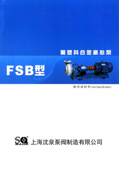
■FSB氟塑料合金离心泵■上海沈泉泵阀制造有限公司☆ 产品概述氟塑料合金是当今世界最优秀的耐腐蚀材料,我单位选用该材料生产的FSB、FSB-D系列泵,具有特强的耐腐蚀性,且机械强度高、不老化、无毒素分解,可输送任意浓度的酸、碱液、氧化剂及其他腐蚀性介质,因而广泛适用于化工、石油、制药、农药、冶炼、染料、造纸、电镀、食品等行业。
☆ 结构说明1、泵体:左右两边连接部分内埋钢质法兰圈各一只模压塑料合金制成。
2、后盖右边一侧内埋一只不锈钢板(1Crl8Ni9Ti)模压塑料合金而成。
3、叶轮:采用接轴连接方法,金属轴为优质钢精加工后夕卜包塑料合金模压而成,使叶轮与金属接轴牢固地结为一体,保证轴根与叶轮后部承受随旋转时的扭矩力,这样介质浸湿部分为塑料合金。
4、机械密封:采用WB2型、ST型不用冷却水可调式端面密封技术,由碳化硅、高纯度氧化铝陶瓷、填充四氟、石墨等材料制成。
☆ 产品结构1 泵体 8 油 盖2 叶轮 9 油 镜3 后盖 10 轴 承4 压盖 11 轴承压盖5 密封件 12 联轴器6 支架 13 吊紧螺栓7 泵轴☆ 型号意义☆ 泵型谱图☆ 性能参数口径 规格型号 流量 m3/h 扬程 m 吸入mm 吐出mm 配用电机KW 转速 r/min 吸上高度m 效率 % 25FSB-10 1.5 10 25 20 1.5 2900 6 29 25FSB-18 3.6 18 25 20 2.2 2900 6 27 40FSB-15 5 15 40 32 3 2900 6 40 40FSB-20 10 20 40 32 4 2900 6 42 40FSB-30 10 30 40 32 4 2900 6 38 40FSB-40 10 40 40 32 5.5 2900 5.5 35 40FSB-50 10 50 40 32 7.5 2900 5 33 50FSB-20 15 20 50 40 4 2900 6 51 50FSB-25 15 25 50 40 4 2900 6 49 50FSB-30 15 30 50 40 4 2900 6 44.5 50FSB-40 15 40 50 32 5.5-7.52900 5.5 35 50FSB-50 15 50 50 32 7.5-112900 5.5 33 50FSB-63 15 63 50 32 11 2900 5.5 30 65FSB-32 29 32 65 50 5.5 2900 6 57 65FSB-40 29 40 65 40 11 2900 5.5 53 65FSB-50 29 50 65 40 15 2900 5.5 46 65FSB-64 29 64 65 50 15-18.52900 5.5 44 80FSB-20 50 20 80 65 5.5 2900 6 69 80FSB-30 50 30 80 65 7.5 2900 5.5 64 80FSB-34 50 34 80 65 11 2900 5.5 64 80FSB-40 50 40 80 50 11-15 2900 5.5 60 80FSB-50 50 50 80 50 15-18.52900 6 53 80FSB-55 50 55 80 50 15-18.52900 5.5 47 80FSB-80 50 80 80 50 30-37 2900 5.5 36 100FSB-32 100 32 100 80 18.5-222900 5.5 70 100FSB-40 100 40 100 80 18.5-222900 5.5 70 100FSB-50100501006522-3029005.562☆ 安装说明1、在安装前应对泵和电机进行检查,各部分应完好无损,泵内无杂物。
黄铜旋塞阀执行标准

黄铜旋塞阀执行标准全文共四篇示例,供读者参考第一篇示例:一、行业标准1. GB/T 8464-2008 建筑给水阀门通用技术条件该标准规定了建筑用给水阀门的分类、型号、规格、材料、标记、包装、运输和储存等要求,适用于黄铜旋塞阀及其他给水阀门的设计、制造和使用。
二、国际标准1. ISO 5208 阀门(金属阀座)-试验该标准规定了阀门(金属阀座)的试验方法,包括密封性试验、耐压试验、耐腐蚀试验等,适用于黄铜旋塞阀及其他金属阀门的质量检验。
2. API 600 钢制闸阀、止回阀、旋塞阀和截止阀该标准规定了钢制闸阀、止回阀、旋塞阀和截止阀的设计、制造和检验要求,适用于黄铜旋塞阀及其他相关阀门产品。
3. ANSI B16.34 阀门-法兰、栓材、阀杆和螺顶螺纹的标准该标准规定了阀门的法兰、栓材、阀杆和螺顶螺纹的标准,适用于黄铜旋塞阀及其他阀门产品的设计和制造。
三、质量检验与认证黄铜旋塞阀作为关键的流体控制设备,其质量和性能直接影响到工业生产和民用设施的正常运行。
质量检验与认证是确保黄铜旋塞阀产品质量的重要环节。
1. 质量检验在黄铜旋塞阀生产过程中,需要对产品进行严格的质量检验,包括外观检查、尺寸检测、性能测试等,确保产品符合相关标准和规范要求。
通常的检验方法包括压力测试、密封性测试、流量测试等,以确保产品的质量和性能稳定可靠。
2. 认证标志黄铜旋塞阀产品在通过质量检验并符合相关标准要求后,可以获得相关的认证标志,如CE认证、ISO认证等。
这些认证标志是对产品质量和性能的有力保证,也可以提升产品在市场竞争中的地位。
3. 质量管理体系黄铜旋塞阀生产企业应建立完善的质量管理体系,包括质量控制流程、质量管理人员培训、质量数据分析等,确保产品质量可追溯、可控制,从而提高产品的质量稳定性和一致性。
四、市场应用与前景展望随着工业生产和民用设施的不断发展,黄铜旋塞阀作为重要的流体控制设备,在市场上具有广阔的应用前景和发展空间。
西安普天7GC~8GC天线参数

40.0 40.8 41.5
1.5
1.30 1.25
64
--
30
单极化 WTG20—W71D
2.0
40.9 41.7 42.4
1.4
1.30 1.25
64
--
30
WTG24—W71D
2.4
42.5 43.3 44.0
1.2
1.30 1.25
65
--
30
WTG25—W71D
பைடு நூலகம்
2.5
42.8 43.6 44.3
0.9
1.30 1.25
67
35
30
安
WTG32—W71S
3.2
44.8 45.6 46.3
0.9
1.30 1.25
68
35
30
普
WTG40—W71S
4.0
46.7 47.5 48.2
0.7
1.30 1.25
70
35
30
天
高交叉极化鉴别率天线
WTJ18—W71S
1.8
39.8 40.6 41.3
1.5
号
电 话 :
传 真 :
42
029-82685308/09/10
029-82681019
40.3 41.1 41.8
1.4
1.30 1.25
53
35
30
双极化
WTB24—W71S
2.4
41.8 42.6 43.4
1.2
1.30 1.25
54
35
30
WTB25—W71S
2.5
42.2 43.0 43.7
安能聚Q08系列变频器说明书

系列产品 单相
功率段 年份周次 编号
安装尺寸图:
外形和安装尺寸:
变频器的型号
外型和安装尺寸(mm)
W
H
D
W1
H1
D1
Q08-2S0004H
Q08-2S0007H
80
155
130
69.3 143 38.5
Q08-2S0015H
Q08-Hale Waihona Puke S0022H Q08-2S0037H
130
120
181
116
208
Q08 系列使用手册
1 序言
感谢您使用 Q08 系列变频器。Q08 系列变频器采用高品质的元件、材料及融合最新的微电脑 控制技术制造而成。
本手册提供给使用者安装、参数设定、异常诊断、排除等的相关注意事项。为了确保能够 正确地安装及操作本变频器,请在装机之前,详细阅读本使用手册,并请妥善保存及交由该机 器的使用者。 以下为特别需要注意的事项:
AI
AO
SG+ SG-
端子功能说明
多功能指示信号输出接 点1
多功能指示信号输出接 点2
多功能输入选择一 多功能输入选择二 多功能输入选择三 多功能输入选择四 多功能输入选择五
多功能输入选择六
频率设定用电源
模拟输入
模拟输出
485 差分信号正端 485 差分信号负端
规格 RA1-RB1:常闭,RA1-RC1:常开
P30
二/三线控制方式
d01 M0:运转/停止;M1:正转/反转
d02 M0、M1、M2:三线式运转控制
出厂 值
00
00
00 50.0 50.0 220.0 1.5 10.0 1.5 10.0 5.0 5.0 5.0 5.0 1.0 6.0 0.0 0.0 0.0 0.0 0.0 0.0 0.0 0.0
电液动蝶阀

电液动蝶阀使用说明书江苏创格流体控制有限公司产品简介:该电液执行器具有安装方便、操作简单、液压集成、远程/本地控制等特点,可与蝶阀、球阀等阀门配套使用,目前已广泛应用于石油化工、冶金、水利、船舶、电力管道等多个领域。
结构特点:驱动机构分单作用和双作用,来实现角位移输出采用高保压元件,效率高,可靠性高。
采用侧装结构,体积小可适用于多种工况。
主要功能:具有本地/远程控制功能系统带液压锁,能更好地锁住压力该电液动机构执行器具有阀位反馈,能直接的看出阀处在什么状态,当执行机构断电的时,可采用手动应急泵对其应急。
规格:执行机构机构部分形式:电液动蝶阀主要由二部分组成:电液动执行器和蝶阀。
防护等级及执行标准:IP67使用环境温度(整机):-10℃~+70℃液压微动力单元H1采用贺尔碧格自动化技术有限公司。
具有响应快速,运行平稳,力矩输出恒定等特点。
液压部分:液压油牌号:N46#抗磨耐压油液压回路:柱塞泵、液压集成块、油箱等组成柱塞泵:电制:220V/50Hz功率:300W转速:3000r/min最大工作电流:4A过载保护:温度开关,设定值140℃工作原理:电器控制部分构成:控制模块、电机驱动模块以及过载保护模块、电源模块等组成。
阀位反馈形式:安装在齿轴顶部。
防护等级:IP67反馈元件:行程开关(寿命可达1万次全程往复运动)蝶阀:蝶阀介质压力:≤1.0MPA蝶阀适用介质:淡水、海水、各种油品及酸碱类电液动蝶阀特点:动作灵敏,运行平稳,能有效缓冲外来的冲击力,行程控制准确,可以带负荷启动,并具有超负荷保护能力。
由于采用机、电、液一体化全封闭结构,工作油路循环于无压的封闭钢筒里,体积小,不漏油,便于安装,维修。
在恶劣的工作环境下,不吸尘,不进水,内部不锈蚀,使用寿命长。
电液动蝶阀工作原理:电液动蝶阀以柱塞泵动力源,通过动力泵输出压力油,经油路集成块的控制送至油缸,实现齿条往复运动,同时通过齿轴转动阀轴、阀板作90度范围内旋转,达到开启关闭阀门。
QGS-08C分析仪使用说明书

ISO14001:2004 ISO9001:2000 GB/T28001-2001
QGS-08C 红外线气体分析器
安装使用说明书
北京北分麦哈克分析仪器有限公司
BAIF-Maihak Analytical Instrument Co.,Ltd.
尊敬的用户: 非常感谢您对我们的信任!
2.1 仪器简介 ................................................................................................................................................. 2 2.2 工作原理 ................................................................................................................................................. 2 2.3 仪器功能 ................................................................................................................................................. 3 3 技术数据........................................................................................................................................................ 5 3.1 应用范围 ................................................................................................................................................. 5 3.2 技术指标 ................................................................................................................................................. 5 3.3 测量值输出 ............................................................................................................................................. 6 3.4 状态输出接点负荷 ................................................................................................................................. 6 3.5 基本参数 ................................................................................................................................................. 6 4 安装................................................................................................................................................................ 7 4.1 供货清单 ................................................................................................................................................. 7
BF和F型耐腐蚀离心泵型号参数说明
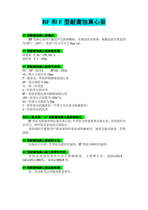
BF和F型耐腐蚀离心泵
BF型耐腐蚀离心泵概述:
BF型离心泵用于输送不含固体颗粒,有腐蚀性的液体,被输送的介质温度为-20℃~105℃,泵进口压力不大于6kg/cm2。
BF型耐腐蚀离心泵参数范围:
流量Q 3.36~190.8m3/h
扬程H 5.2~100m
BF型耐腐蚀离心泵型号说明:
例:40F-65ⅡA BF180-80IA
40-吸入口直径为40mm
F-悬架式、单级单吸耐腐蚀离心泵
65-设计扬程为65m
Ⅱ-第二次改进
A-叶轮外径的改变
BF-单级单吸托架式耐腐蚀离心泵
180-泵设计点流量为180m3/h
80-泵设计点扬程为80m
I-带外装式机械密封(不带I为内装式机械密封)
A-叶轮外径的改变
长沙三昌水泵厂BF型耐腐蚀离心泵结构型式:
BF型泵为单级单吸托架式离心泵;F型泵为单级悬架式离心泵,其结构均为后开门,即叶轮从泵体的后面取出。
泵的轴封可根据用户要求装填料密封或机械密封。
轴承为滚动轴承,用脂润滑。
BF型耐腐蚀离心泵旋转方向:
从驱动方向看,F型泵为逆时针旋转;BF型泵为顺时针旋转。
BF型耐腐蚀离心泵主要零件材质:
泵的过流部件采用合金不锈钢铸造。
主要牌号有:ZG1Cr18Ni9,ZGCr18Ni12M02Ti,ZG1Cr19M02R等。
BF型耐腐蚀离心泵成套范围:
泵、电动机及公用底座配套供应。
247。
PC3Q67QY资料

1.Recognized by UL1577 (Double protection isolation), file No. E64380 (as model No. PC3Q67Q )2.Approved by VDE, VDE0884 (as an option), file No. 5992UG (as model No. PC3Q67Q )3. Package resin : UL flammability grade (94V-0)■ Features■ Agency approvals/Compliance1. Programmable controllers■ ApplicationsMini-flat Half Pitch 4-channel Package,General Purpose Photocoupler1. 4 channel Mini-flat Half pitch package (Lead pitch : 1.27mm)2. Double transfer mold package (Ideal for Flow Solder-ing)3. High collector-emitter voltage (V CEO : 80V (*) )4. Current transfer ratio (CTR : MIN. 50% at I F =5mA, V CE =5V)5. Isolation voltage between input and output (V iso(rms) : 2.5kV)(*) Up to Date code "P9" (September 2002) V CEO : 35V.From the production Date code "J5" (May 1997) to "P9" (September 2002), however the products were screened by BV CEO ≥70V.■ DescriptionPC3Q67Q Series contains an IRED optically cou-pled to a phototransistor.It is packaged in a 4 channel Mini-flat package, Half ptich type.Input-output isolation voltage(rms) is 2.5kV.Collector-emitter voltage is 80V (*) and CTR is 50% to 600% at input current of 5mA.Notice The content of data sheet is subject to change without prior notice.In the absence of confirmation by device specification sheets, SHARP takes no responsibility for any defects that may occur in equipment using any SHARP PC3Q67Q Series∗1-channel package type is also available. (model No. PC3H7 Series )■ Internal Connection DiagramAnode Cathode Emitter Collector■ Outline DimensionsProduct mass : approx. 0.3g(Unit : mm)Date code (3 digit)A.D. 1990 1991 1992 1993 1994 1995 1996 1997 1998 1999 2000 2001MarkABCDEFHJKLMNMarkPRSTUVWXABCMark123456789ONDMonthJanuaryFebruaryMarchAprilMayJuneJulyAugustSeptemberOctoberNovemberDecemberA.D20022003200420052006200720082009201020112012······2nd digitMonth of productionMark12345Week1st2nd3rd4th5, 6th3rd digitWeek of production 1st digitYear of productionrepeats in a 20 year cycle Country of originJapan■ Electro-optical CharacteristicsParameter ConditionsForward voltage Reverse CurrentTerminal capacitance Collector dark current Transfer charac-teristicsEmitter-collector breakdown voltage Collector current Collector-emitter breakdown voltage Collector-emitter saturation voltage Isolation resistance Floating capacitanceMIN.−−−−62.5−5×10¹⁰−−−TYP.1.2−30−−−5.00.11×10110.643MAX.1.410250100−−30.00.2−1.01818Unit V V µA pF nA V mA V ΩpF µs µsSymbol V FI R C t I CEO BV CEO BV ECO I C V CE (sat)C f t r t fR ISOResponse timeRise timeFall time InputOutputI F =20mA V R =4V V =0, f =1kHz V CE =50V, I F =0 I C =0.1mA, I F =0 I E =10µA, I F =0 I F =5mA, V CE =5V DC500V, 40 to 60%RHV CE =2V, I C =2mA, R L =100ΩV =0, f =1MHzI F =20mA, I C =1mA 80*5(T a =25˚C)*5 From the production Date code "J5" (May 1997) to "P9" (September 2002), however the products were screened by BV CEO ≥70V.■ Absolute Maximum Ratings(T a =25˚C)Parameter Symbol UnitI n p u tForward current mA *1Peak forward current APower dissipation mW O u t p u t Collector-emitter voltage VEmitter-collector voltage V Collector current mA Collector power dissipation mWTotal power dissipation mW*2Isolation voltage Operating temperature ˚CStorage temperature ˚C*3Soldering temperature I FI FM PV CEO V ECO I C P C P tot V iso (rms)T opr T stg T sol ˚C*1 Pulse width ≤100µs, Duty ratio : 0.001*2 40 to 60%RH, AC for 1 minute, f=60Hz *3 For 10s*4 Up to Date code "P9" (September 2002) V CEO : 35V.Rating 50170Reverse voltage V V R 680650150170−30 to +100−40 to +1252602.5kV *4■ Model Line-upPlease contact a local SHARP sales representative to inquire about production status and Lead-Free options.VDE0884Model No.Package PC3Q67QYApproved PC3Q67Q -Taping 1 000pcs/reelT o t a l p o w e r d i s s i p a t i o n P t o t (m W )050100150200250170−300255075100125Ambient temperature T a (˚C)Fig.4 Total Power Dissipation vs. AmbientTemperatureForward voltage V F (V)00.5 1.0 1.5 2.0110100F o r w a r d c u r r e n t I F (m A )Fig.6 Forward Current vs. Forward VoltageDuty ratio55Pulse width ≤100ms Ta =25˚C102010050200500210−310−25210−1525P e a k f o r w a r d c u r r e n t I F M (m A )110 0005 0002 0001 000Fig.5 Peak Forward Current vs. Duty RatioF o r w a r d c u r r e n t I F (m A )01020304050−30025********5550Ambient temperature T a (˚C)Fig.1 Forward Current vs. AmbientTemperature02040607080100−30025********5550Ambient temperature T a (˚C)D i o d e p o w e r d i s s i p a t i o n P (m W )Fig.2 Diode Power Dissipation vs. AmbientTemperatureC o l l e c t o r p o w e r d i s s i p a t i o n P C (m W )050100150200250−300255075100125Ambient temperature T a (˚C)Fig.3 Collector Power Dissipation vs.Ambient Temperature555555806040200−3010010−510−610−710−810−910−1010−11C o l l e c t o r d a r k c u r r e n t I C E O (A )Ambient temperature T a (˚C)V CE =50VFig.11 Collector Dark Current vs. AmbientTemperature0.10.20.51251020502001001005001010.10.01t f t st dt r R e s p o n s e t i m e (µs )V CE =2VI C =2mA T a =25˚C 1 000Load resistance R L (k Ω)Fig.12 Response Time vs. Load ResistanceR e l a t i v e c u r r e n t t r a n s f e r r a t i o (%)0%150%100%50%Ambient temperature T a (˚C)Fig.9 Relative Current Transfer Ratio vs.Ambient Temperature0.020.000.040.060.080.100.120.140.16C o l l e c t o r -e m i t t e r s a t u r a t i o n v o l t a g e V C E (s a t ) (V )I F =20mA I C =1mAAmbient temperature T a (˚C)020*********−30Fig.10 Collector - emitter Saturation Voltagevs. Ambient Temperature2465040302010810C o l l e c t o r c u r r e n t I C (m A )Collector-emitter voltage V CE (V)Fig.8 Collector Current vs. Collector-emitterVoltageC u r r e n t t r a n s f e r r a t i o C T R (%)05004003002001000.1110100Forward current I F (mA)V CE =5V T a =25˚CFig.7 Current Transfer Ratio vs. ForwardCurrentRemarks : Please be aware that all data in the graph are just for reference and not for guarantee.8642024681010C o l l e c t o r -e m i t t e r s a t u r a t i o n v o l t a g e V C E (s a t ) (V )Forward current I F (mA)Fig.14 Collector-emitter Saturation Voltagevs. Forward CurrentPlease refer to the conditions in Fig.12Fig.13 Test Circuit for Response TimeWhile operating at I F <1.0mA, CTR variation may increase.Please make design considering this fact.This product is not designed against irradiation and incorporates non-coherent IRED.● DegradationIn general, the emission of the IRED used in photocouplers will degrade over time.In the case of long term operation, please take the general IRED degradation (50% degradation over 5years) into the design consideration.✩ For additional design assistance, please review our corresponding Optoelectronic Application Notes.● Recommended Foot Print (reference)(Unit : mm)● Design guide■ Design Considerations■ Manufacturing Guidelines Reflow Soldering :Reflow soldering should follow the temperature profile shown below.Soldering should not exceed the curve of temperature profile and time.Please don't solder more than twice.● Soldering Method Flow Soldering :Due to SHARP's double transfer mold construction submersion in flow solder bath is allowed under the below listed guidelines.Flow soldering should be completed below 260˚C and within 10s.Preheating is within the bounds of 100 to 150˚C and 30 to 80s.Please don't solder more than twice.Hand solderingHand soldering should be completed within 3s when the point of solder iron is below 400˚C.Please don't solder more than twice.Other noticesPlease test the soldering method in actual condition and make sure the soldering works fine, since the impact on the junction between the device and PCB varies depending on the tooling and soldering conditions.12343002001000(˚C)(min)● Cleaning instructionsSolvent cleaning:Solvent temperature should be 45˚C or below Immersion time should be 3minutes or lessUltrasonic cleaning:The impact on the device varies depending on the size of the cleaning bath, ultrasonic output, cleaning time, size of PCB and mounting method of the device.Therefore, please make sure the device withstands the ultrasonic cleaning in actual conditions in advance of mass production.Recommended solvent materials:Ethyl alcohol, Methyl alcohol and Isopropyl alcoholIn case the other type of solvent materials are intended to be used, please make sure they work fine in ac-tual using conditions since some materials may erode the packaging resin.● Presence of ODCThis product shall not contain the following materials.And they are not used in the production process for this device.Regulation substances : CFCs, Halon, Carbon tetrachloride, 1.1.1-Trichloroethane (Methylchloroform)Specific brominated flame retardants such as the PBBOs and PBBs are not used in this product at all.■ Package specification● Tape and Reel packagePackage materialsCarrier tape : PSCover tape : PET (three layer system)Reel : PSCarrier tape structure and DimensionsA 24.0±0.3B11.5±0.1C1.75±0.1D12.0±0.1E2.0±0.1H 10.8±0.1I 0.4±0.05J3.0±0.1K7.4±0.1F4.0±0.1Gφ1.5+0.1−0Dimensions List(Unit : mm)a330b25.5±1.5c100±1.0d13±0.5e23±1.0f2.0±0.5g2.0±0.5Pull-out direction[Packing : 1 000pcs/reel] Reel structure and DimensionsDirection of product insertion· The circuit application examples in this publication are provided to explain representative applications ofSHARP devices and are not intended to guarantee any circuit design or license any intellectual property rights. SHARP takes no responsibility for any problems rela-ted to any intellectual property right of a third party re-sulting from the use of SHARP's devices.· Contact SHARP in order to obtain the latest device specification sheets before using any SHARP device. SHARP reserves the right to make changes in the spec-ifications, characteristics, data, materials, structure, and other contents described herein at any time without notice in order to improve design or reliability. Manufac-turing locations are also subject to change without no-tice.· Observe the following points when using any devices in this publication. SHARP takes no responsibility for damage caused by improper use of the devices which does not meet the conditions and absolute maximum ratings to be used specified in the relevant specification sheet nor meet the following conditions:(i) The devices in this publication are designed for use in general electronic equipment designs such as:--- Personal computers--- Office automation equipment--- Telecommunication equipment [terminal]--- Test and measurement equipment --- Industrial control--- Audio visual equipment --- Consumer electronics(ii) Measures such as fail-safe function and redundant design should be taken to ensure reliability and safety when SHARP devices are used for or in connectionwith equipment that requires higher reliability such as:--- Transportation control and safety equipment (i.e.,aircraft, trains, automobiles, etc.)--- Traffic signals--- Gas leakage sensor breakers --- Alarm equipment--- Various safety devices, etc.(iii) SHARP devices shall not be used for or in connec-tion with equipment that requires an extremely high lev-el of reliability and safety such as:--- Space applications--- Telecommunication equipment [trunk lines]--- Nuclear power control equipment--- Medical and other life support equipment (e.g.,scuba).· If the SHARP devices listed in this publication fall with-in the scope of strategic products described in the For-eign Exchange and Foreign Trade Law of Japan, it is necessary to obtain approval to export such SHARP de-vices.· This publication is the proprietary product of SHARP and is copyrighted, with all rights reserved. Under the copyright laws, no part of this publication may be repro-duced or transmitted in any form or by any means, elec-tronic or mechanical, for any purpose, in whole or in part, without the express written permission of SHARP. Express written permission is also required before any use of this publication may be made by a third party.· Contact and consult with a SHARP representative if there are any questions about the contents of this pub-lication.■Important Notices。
【精品】航空电缆简介

航空航天电缆产品浅说(供非专业人员参考)本网采访编辑航空航天电缆的基本要求是重量轻、直径小、耐温高和耐磨性好,此外应能耐燃料油、润滑油和其他化学溶剂等。
当前我国航空航天电缆以国家军标GJB773A-2000《航空航天用含氟聚合物绝缘电线电缆通用规范》为主要体系,聚酰亚胺复合薄膜绕包绝缘已很少不用。
该规范适用于含氟聚合物绝缘电线电缆产品(以下简称航空电缆),主要包括聚四氟乙烯(PTFE),聚全氟乙丙烯(FEP),聚偏氟乙烯(PVDF),乙烯─四氟乙烯共聚物(ETFE),交联乙烯─四氟乙烯共聚物(XETFE),四氟乙烯-全氟烷基乙烯基醚共聚物(PFA)和其他含氟聚合物。
这些聚合物可单独使用,也可以与其它材料组合使用。
本节只介绍部分品种。
1.导体材料和结构导体有镀锡铜线、镀银铜线、镀镍铜线、镀锡铜合金线、镀银铜合金线、镀镍铜合金线和铝线(JL型)。
镀层限制使用温度:锡为150℃,银为200℃,镍为250℃。
参考GJB1640-1993《航空航天电线电缆用导体品种级截面系列》标准,同心绞合铜导体截面、结构尺寸及20℃时直流电阻见表1,同心绞合铜合金导体截面、结构尺寸及20℃直流电阻见表2,束绞铜导体截面、结构尺寸及20℃直流电阻见表3,同心绞铝导体截面、结构尺寸及直流电阻见表4。
截面为0.5 mm2以下铜导体的断裂伸长率应不小于6%,截面0.5 mm2及以上铜导体的断裂伸长率应不小于10%。
铜合金导体和铝导体全部截面规格断裂伸长率应不小于6%。
铜合金单线的抗拉强度应不小于490MPa。
其电阻率不大于0.02196Ω·mm2/m。
导体绞合节距的节径比倍数应不大于表5的规定。
另一方面,应当检查各种单线的表面质量,特别应注意镀银单线的表面发黑问题。
此外,也应注意绞线时单线镀层的擦伤和脱落。
2.绝缘材料及其缩写聚四氟乙烯(PTFE)挤制绝缘及加有耐磨填料的聚四氟乙烯(PTFE)挤制绝缘(F4)。
聚全氟乙丙烯(FEP)挤制绝缘(F46)。
- 1、下载文档前请自行甄别文档内容的完整性,平台不提供额外的编辑、内容补充、找答案等附加服务。
- 2、"仅部分预览"的文档,不可在线预览部分如存在完整性等问题,可反馈申请退款(可完整预览的文档不适用该条件!)。
- 3、如文档侵犯您的权益,请联系客服反馈,我们会尽快为您处理(人工客服工作时间:9:00-18:30)。
BFQ67 / BFQ67R / BFQ67WVishay Semiconductors3Not for new design, this product will be obsoleted soonSilicon NPN Planar RF TransistorFeatures•Small feedback capacitance•Low noise figure•High transition frequency•Lead (Pb)-free component•Component in accordance to RoHS 2002/95/ECand WEEE 2002/96/ECApplicationsLow noise small signal amplifiers up to 2 GHz. Thistransistor has superior noise figure and associatedgain performance at UHF, VHF and microwave fre-quencies.Mechanical DataTyp: BFQ67Case: SOT-23 Plastic caseWeight: approx. 8.0 mgMarking: V2Pinning: 1 = Collector, 2 = Base, 3 = EmitterTyp: BFQ67RCase: SOT-23 Plastic caseWeight: approx. 8.0 mgMarking: R67Pinning: 1 = Collector, 2 = Base, 3 = EmitterTyp: BFQ67WCase: SOT-323 Plastic caseWeight: approx. 6.0 mgMarking: WV2Pinning: 1 = Collector, 2 = Base, 3 = EmitterAbsolute Maximum RatingsT amb = 25°C, unless otherwise specifiedParameter T est condition Symbol Value Unit Collector-base voltage V CBO20VCollector-emitter voltage V CEO10VEmitter-base voltage V EBO 2.5VCollector current I C50mAT otal power dissipation T amb≤ 60°C P tot200mWJunction temperature T j150°CStorage temperature range T stg- 65 to + 150°C元器件交易网BFQ67 / BFQ67R / BFQ67WVishay Semiconductors Maximum Thermal Resistance1)on glass fibre printed board (25 x 20 x 1.5) mm 3 plated with 35 μm CuElectrical DC CharacteristicsT amb = 25°C, unless otherwise specifiedElectrical AC CharacteristicsT amb = 25°C, unless otherwise specifiedParameterTest condition Symbol Value Unit Junction ambient1)R thJA450K/WParameterTest conditionSymbol MinTyp.Max Unit Collector-emitter cut-off current V CE = 20 V , V BE = 0I CES 100μA Collector-base cut-off current V CB = 15 V , I E = 0I CBO 100nA Emitter-base cut-off current V EB = 1 V , I C = 0I EBO 1μA Collector-emitter breakdown voltageI C = 1 mA, I B = 0V (BR)CEO 10V Collector-emitter saturation voltageI C = 50 mA, I B = 5 mAV CEsat 0.10.4VDC forward current transfer ratio V CE = 5 V , I C = 15 mAh FE65100150ParameterTest conditionSymbol MinTyp.MaxUnit Transition frequency V CE = 8 V , I C = 15 mA, f = 500 MHzf T 7.5GHz Collector-base capacitance V CB = 10 V , f = 1 MHz C cb 0.4pF Collector-emitter capacitance V CE = 8 V , f = 1 MHz C ce 0.2pF Emitter-base capacitance V EB = 0.5 V , f = 1 MHz C eb 0.85pF Noise figureV CE = 8 V , Z S = Z Sopt , f = 800 MHz, I C = 5 mA F 0.8dB V CE = 8 V , Z S = Z Sopt , f = 800 MHz, I C = 15 mA F 1.5dB V CE = 8 V , Z S = 50 Ω, f = 2 GHz, I C = 5 mAF 2.5dB V CE = 8 V , Z S = 50 Ω, f = 2 GHz, I C = 15 mAF 3.0dB Power gainV CE = 8 V , Z S = 50 Ω, Z L = Z Lopt , I C = 15 mA, f = 800 MHz G pe 15.5dB V CE = 8 V , Z S = 50 Ω, Z L = Z Lopt , I C = 15 mA, f = 2 GHzG pe 8dB Linear output voltage - two tone intermodulation test V CE = 8 V , I C = 15 mA, d IM = 60 dB, f 1 = 806 MHz,f 2 = 810 MHz, Z S = Z L = 50 ΩV 1 = V 2160mVThird order intercept pointV CE = 8 V , I C = 15 mA, f = 800 MHzIP 326dBmBFQ67 / BFQ67R / BFQ67WVishay SemiconductorsCommon Emitter S-ParametersZ0 = 50 Ω, T amb = 25°C, unless otherwise specifiedV CE/V I C/mA f/MHz S11S21S12S22LIN MAG ANG LINMAGANG LINMAGANG LINMAGANG deg deg deg deg521000.894-20.6 6.78163.00.02777.10.967-8.7 3000.749-56.2 5.61136.20.06659.20.834-20.85000.610-83.8 4.50117.70.08650.00.716-25.98000.486-116.2 3.3698.80.10246.30.623-28.610000.445-132.4 2.8790.20.10946.90.590-30.112000.419-147.3 2.5081.90.11548.70.568-31.815000.402-166.6 2.1271.70.12653.10.546-35.018000.403177.0 1.8362.80.14258.10.531-38.820000.411167.0 1.6958.00.15660.80.524-41.922000.423158.5 1.5953.00.17363.20.516-45.125000.445146.1 1.4545.80.20265.20.511-51.728000.464137.1 1.3439.10.23265.50.490-59.130000.490130.5 1.2734.70.25564.70.471-64.8 551000.760-32.114.10154.10.02472.70.912-15.2 3000.522-79.09.62121.50.05258.50.663-27.95000.390-108.5 6.72104.70.06757.00.538-28.18000.311-139.1 4.5689.90.08860.00.473-26.310000.292-153.5 3.7783.10.10362.10.459-26.412000.282-166.5 3.2176.70.11963.60.450-27.415000.287178.0 2.6768.30.14364.70.438-30.418000.298164.0 2.2960.90.16965.50.428-34.220000.313157.1 2.1056.60.18965.20.423-37.122000.328149.6 1.9652.50.20964.80.415-40.225000.353140.6 1.7946.40.23963.50.406-46.828000.379133.2 1.6539.40.26761.50.380-53.830000.400127.4 1.5535.40.28659.80.358-58.9 5101000.594-46.322.01144.40.02169.80.829-21.7 3000.346-101.612.12110.80.04363.50.524-29.95000.264-130.97.8697.10.06066.00.431-25.78000.230-158.2 5.1385.10.08869.00.399-21.910000.224-169.5 4.2179.50.10769.70.396-21.812000.225179.8 3.5673.90.12669.60.393-23.315000.235166.8 2.9466.80.15468.60.387-26.618000.251156.9 2.5159.90.18467.60.379-30.720000.270150.2 2.3056.00.20666.20.374-33.722000.287144.1 2.1452.10.22665.10.366-36.925000.310136.4 1.9546.20.25662.60.354-43.628000.342131.0 1.7939.90.28460.10.325-50.530000.362125.6 1.6835.90.30257.80.301-55.3 5151000.477-56.726.58138.30.01969.70.7681-25.3BFQ67 / BFQ67R / BFQ67WVishay Semiconductors3000.276-116.413.06106.10.03967.80.4623-29.25000.221-144.48.2594.00.05970.90.3912-23.18000.208-169.5 5.3483.20.08872.50.3733-19.110000.206-177.8 4.3578.00.10972.30.3734-19.412000.208172.5 3.6872.80.12971.60.3736-21.115000.221162.5 3.0365.90.15969.90.3686-24.718000.237154.0 2.5859.30.19068.20.3619-29.020000.257147.5 2.3755.70.21266.70.3561-32.122000.280142.4 2.2152.10.23265.20.3474-35.425000.303135.4 2.0146.10.26262.40.3343-42.228000.329130.0 1.8539.70.29059.50.3053-49.130000.357124.8 1.7336.00.30857.10.2807-53.75201000.397-66.029.45134.10.01769.80.722-27.53000.240-128.213.50103.40.03871.10.427-28.15000.205-153.88.4392.30.05873.50.370-21.08000.199-175.5 5.4382.00.08974.30.360-17.310000.195176.6 4.4277.10.11073.80.362-17.712000.202168.2 3.7372.00.13172.50.363-19.715000.219159.0 3.0865.50.16270.50.359-23.618000.235151.5 2.6259.00.19368.60.352-28.020000.252145.7 2.4055.20.21566.80.346-31.122000.274140.0 2.2451.60.23565.30.338-34.525000.300134.2 2.0346.00.26562.40.325-41.128000.326129.2 1.8739.60.29359.40.295-48.330000.357124.8 1.7635.80.31157.00.270-52.95301000.301-82.032.38128.80.01671.90.662-29.43000.219-143.613.79100.30.03674.70.393-25.75000.201-165.88.5290.30.05776.50.352-18.38000.198176.3 5.4680.60.09076.10.350-15.210000.201170.4 4.4375.90.11175.20.354-16.012000.204163.8 3.7571.10.13373.50.356-18.215000.222156.2 3.0964.50.16471.30.353-22.318000.242149.4 2.6258.10.19569.20.346-26.920000.263144.6 2.4054.40.21667.30.340-30.222000.279139.7 2.2450.90.23865.60.332-33.625000.308133.6 2.0345.00.26762.40.318-40.728000.336128.8 1.8639.20.29559.40.288-47.630000.365124.1 1.7535.00.31356.80.264-52.1821000.900-19.96.84163.20.02676.90.967-8.4V CE /VI C /mAf/MHzS11S21S12S22LIN MAGANG LIN MAGANG LIN MAGANG LIN MAGANG deg deg deg degBFQ67 / BFQ67R / BFQ67WVishay Semiconductors3000.751-54.9 5.70136.60.06359.90.838-20.15000.615-82.0 4.59118.30.08350.70.724-25.08000.480-113.9 3.4399.50.09847.10.632-27.610000.440-130.1 2.9490.80.10547.80.601-29.012000.408-145.1 2.5582.70.11249.80.579-30.815000.391-164.8 2.1672.40.12354.20.556-33.818000.390178.5 1.8763.50.13859.00.544-37.620000.398168.6 1.7358.40.15361.70.536-40.422000.407159.6 1.6254.00.16964.20.529-43.525000.429147.7 1.4846.70.19865.90.523-49.728000.454138.6 1.3739.90.22666.30.502-56.830000.474131.5 1.2935.20.24965.30.482-62.1 851000.777-30.514.06154.70.02373.10.916-14.5 3000.532-76.29.71122.40.05058.90.675-26.75000.391-104.5 6.82105.50.06557.30.552-27.28000.306-135.8 4.6490.50.08660.40.489-25.310000.283-149.1 3.8483.70.10162.30.473-25.512000.268-163.0 3.2777.30.11663.80.466-26.515000.271-180.0 2.7269.10.13965.10.454-29.418000.281166.6 2.3361.50.16565.90.445-33.020000.298158.8 2.1457.30.18465.60.440-35.722000.312151.8 2.0053.20.20465.30.432-38.825000.339142.4 1.8246.80.23264.10.424-45.028000.369134.7 1.6840.10.26062.20.397-51.630000.388128.9 1.5735.80.27860.20.373-56.0 8101000.618-43.721.93145.30.02070.60.837-20.6 3000.356-96.412.30111.70.04263.60.542-28.75000.262-125.08.0197.80.05966.00.448-24.98000.218-153.5 5.2485.60.08668.90.417-21.110000.211-164.9 4.2880.10.10469.70.413-21.112000.205-175.7 3.6374.60.12369.60.411-22.515000.219170.4 3.0067.40.15068.80.404-25.918000.235158.9 2.5660.50.18067.80.398-29.720000.249152.1 2.3456.80.20066.60.392-32.522000.268145.5 2.1952.80.22165.40.384-35.625000.294138.8 1.9946.90.25063.10.373-42.028000.322132.3 1.8340.40.27660.40.343-48.430000.352126.8 1.7236.30.29458.00.316-52.2 8151000.512-52.826.62139.40.01970.30.780-24.0V CE/V I C/mA f/MHz S11S21S12S22LINMAGANG LINMAGANG LINMAGANG LINMAGANGdeg deg deg degBFQ67 / BFQ67R / BFQ67WVishay SemiconductorsTypical Characteristics (Tamb = 25 °C unless otherwise specified)3000.279-109.213.28106.80.03967.40.480-28.05000.215-137.08.4394.60.05770.30.408-22.18000.191-164.4 5.4683.60.08672.10.391-18.510000.186-173.2 4.4478.50.10772.10.391-18.912000.189177.0 3.7673.40.12671.50.392-20.415000.203164.6 3.1066.60.15569.80.386-24.018000.219155.3 2.6560.10.18568.40.380-28.120000.238148.9 2.4256.10.20666.90.374-31.022000.252143.5 2.2652.60.22665.50.367-34.125000.282136.5 2.0546.80.25662.90.355-40.728000.312130.7 1.8840.70.28260.20.325-47.230000.335126.0 1.7736.70.30057.80.302-51.48201000.436-60.629.61135.10.01769.80.735-26.13000.239-118.913.78104.10.03770.40.444-26.95000.192-147.08.6292.80.05772.90.387-20.38000.178-170.5 5.5582.50.08773.80.378-16.710000.177-179.4 4.5177.50.10873.40.380-17.212000.176172.3 3.8272.60.12872.40.382-19.215000.195161.7 3.1566.00.15770.60.378-22.918000.214153.4 2.6959.60.18868.80.371-27.220000.229148.2 2.4556.10.20967.20.366-30.122000.251142.5 2.2852.40.23065.60.358-33.425000.275135.6 2.0846.50.25862.80.345-40.028000.304130.5 1.9140.70.28659.90.316-46.530000.333125.81.7936.40.30357.60.292-50.8V CE /VI C /mAf/MHzS11S21S12S22LIN MAGANG LIN MAGANG LIN MAGANG LIN MAGANG deg deg deg deg Figure 1. Total Power Dissipation vs. Ambient Temperature 05010015020025030002040608010012014016096 12159P - T o t a l P o w e r D i s s i p a t i o n (m W )t o t T am b - Am b ient Temperat u re (°C)Figure 2. Transition Frequency vs. Collector Current20004000600080001000001020304050I C –Collector Current (mA )12867f –T r a n s i t i o n F r e q u e n c y (M H z )TBFQ67 / BFQ67R / BFQ67WVishay Semiconductors Figure3. Collector Base Capacitance vs. Collector Base VoltageFigure4. Noise Figure vs. Collector Current0.00.20.40.60.81.0048121620V CB–Collector Base Voltage(V)12884C–CollectorBaseCapacitance(pF)cb123450510152025I C–Collector Current(mA)12869F–NoiseFigure(dB)BFQ67 / BFQ67R / BFQ67WVishay SemiconductorsV CE = 8 V, I C = 15 mA, Z 0 = 50 ΩS 11S 12S 21S 22Figure 5. Input Reflection Coefficient Figure 6. Reverse Transmission Coefficient 12998jı∞129990°180°°°Figure 7. Forward Transmission CoefficientFigure 8. Output Reflection Coefficient130000°180°°°13501j∞BFQ67 / BFQ67R / BFQ67WVishay Semiconductors Package Dimensions in mm (Inches)Package Dimensions in mm (Inches)BFQ67 / BFQ67R / BFQ67WVishay SemiconductorsPackage Dimensions in mm (Inches)BFQ67 / BFQ67R / BFQ67WDocument Number 85022Rev. 1.6, 08-Sep-08Vishay Semiconductors 11Ozone Depleting Substances Policy StatementIt is the policy of Vishay Semiconductor GmbH to1.Meet all present and future national and international statutory requirements.2.Regularly and continuously improve the performance of our products, processes, distribution and operating systems with respect to their impact on the health and safety of our employees and the public, as well as their impact on the environment.It is particular concern to control or eliminate releases of those substances into the atmosphere which are known as ozone depleting substances (ODSs).The Montreal Protocol (1987) and its London Amendments (1990) intend to severely restrict the use of ODSs and forbid their use within the next ten years. Various national and international initiatives are pressing for an earlier ban on these substances.Vishay Semiconductor GmbH has been able to use its policy of continuous improvements to eliminate the use of ODSs listed in the following documents.1.Annex A, B and list of transitional substances of the Montreal Protocol and the London Amendments respectively2.Class I and II ozone depleting substances in the Clean Air Act Amendments of 1990 by the Environmental Protection Agency (EPA) in the USA3.Council Decision 88/540/EEC and 91/690/EEC Annex A, B and C (transitional substances) respectively.Vishay Semiconductor GmbH can certify that our semiconductors are not manufactured with ozone depleting substances and do not contain such substances.We reserve the right to make changes to improve technical designand may do so without further notice.Parameters can vary in different applications. All operating parameters must be validated for eachcustomer application by the customer. Should the buyer use Vishay Semiconductors products for anyunintended or unauthorized application, the buyer shall indemnify Vishay Semiconductors against allclaims, costs, damages, and expenses, arising out of, directly or indirectly, any claim of personaldamage, injury or death associated with such unintended or unauthorized use.Vishay Semiconductor GmbH, P.O.B. 3535, D-74025 Heilbronn, Germany元器件交易网Document Number: 91000 Revision: 18-Jul-081DisclaimerLegal Disclaimer NoticeVishayAll product specifications and data are subject to change without notice.Vishay Intertechnology, Inc., its affiliates, agents, and employees, and all persons acting on its or their behalf (collectively, “Vishay”), disclaim any and all liability for any errors, inaccuracies or incompleteness contained herein or in any other disclosure relating to any product.Vishay disclaims any and all liability arising out of the use or application of any product described herein or of any information provided herein to the maximum extent permitted by law. The product specifications do not expand or otherwise modify Vishay’s terms and conditions of purchase, including but not limited to the warranty expressed therein, which apply to these products.No license, express or implied, by estoppel or otherwise, to any intellectual property rights is granted by this document or by any conduct of Vishay.The products shown herein are not designed for use in medical, life-saving, or life-sustaining applications unless otherwise expressly indicated. Customers using or selling Vishay products not expressly indicated for use in such applications do so entirely at their own risk and agree to fully indemnify Vishay for any damages arising or resulting from such use or sale. Please contact authorized Vishay personnel to obtain written terms and conditions regarding products designed for such applications.Product names and markings noted herein may be trademarks of their respective owners.元器件交易网。
