JE91I24HTR4中文资料
AO4924中文资料
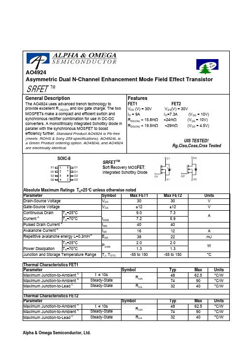
AO4924Asymmetric Dual N-Channel Enhancement Mode Field Effect TransistorAO4924SymbolMin TypMaxUnits BV DSS 30V V DS =24V, V GS =0V0.010.1T J =125°C510I GSS 0.1µA V GS(th)Gate Threshold Voltage 1.5 1.852.4V I D(ON)40A 1315.8T J =125°C20.025.015.719.5m Ωg FS 64S V SD 0.40.6V I S4.5A C iss 14501885pF C oss 224pF C rss92pF R g 1.6 3 ΩQ g (10V)24.031Q g (4.5V)12.0nC Q gs 3.9nC Q gd 4.2nC t D(on) 5.5ns t r 4.7ns t D(off)24.0ns t f 4.0ns t rr 1013ns Q rr6.8nCTHIS PRODUCT HAS BEEN DESIGNED AND QUALIFIED FOR THE CONSUMER MARKET. APPLICATIONS OR USES AS CRITICAL COMPONENTS IN LIFE SUPPORT DEVICES OR SYSTEMS ARE NOT AUTHORIZED. AOS DOES NOT ASSUME ANY LIABILITY ARISING OUT OF SUCH APPLICATIONS OR USES OF ITS PRODUCTS. AOS RESERVES THE RIGHT TO IMPROVE PRODUCT DESIGN,FUNCTIONS AND RELIABILITY WITHOUT NOTICE.Body Diode Reverse Recovery Time Body Diode Reverse Recovery ChargeI F =9A, dI/dt=300A/µsDrain-Source Breakdown Voltage On state drain currentI D =1mA, V GS =0V V GS =4.5V, V DS =5V V GS =10V, I D =9AReverse Transfer CapacitanceI F =9A, dI/dt=300A/µs V DS =V GS I D =250µA FET1 Electrical Characteristics (T J =25°C unless otherwise noted)STATIC PARAMETERS Parameter Conditions I DSS Zero Gate Voltage Drain Current mA V DS =0V, V GS = ±12V Gate-Body leakage current R DS(ON)Static Drain-Source On-ResistanceForward TransconductanceDiode Forward VoltageMaximum Body-Diode + Schottky Continuous CurrentInput Capacitance Output Capacitance DYNAMIC PARAMETERS m ΩV GS =4.5V, I D =7AI S =1A,V GS =0V V DS =5V, I D =9ATurn-On Rise Time Turn-Off DelayTime V GS =10V, V DS =15V, R L =1.7Ω, R GEN =3ΩTurn-Off Fall TimeTurn-On DelayTime Total Gate Charge V GS =10V, V DS =15V, I D =9AGate Drain Charge V GS =0V, V DS =15V, f=1MHzSWITCHING PARAMETERS Total Gate Charge Gate Source Charge Gate resistance V GS =0V, V DS =0V, f=1MHz A: The value of R θJA is measured with the device in a still air environment with T A =25°C. The power dissipation P DSM and current rating I DSM are based on T (J(MAX)=150°C, using t ≤ 10s junction-to-ambient thermal resistance.B: Repetitive rating, pulse width limited by junction temperature T J(MAX)=150°C.C. The R θJA is the sum of the thermal impedence from junction to lead R θJL and lead to ambient.D. The static characteristics in Figures 1 to 6 are obtained using <300 µs pulses, duty cycle 0.5% max.E. These tests are performed with the device mounted on 1 in 2 FR-4 board with 2oz. Copper, in a still air environment with T A =25°C. The SOA curve provides a single pulse rating. Rev0:Sept. 2006AO4924AO4924AO4924AO4924SymbolMin TypMaxUnits BV DSS 30V 1T J =55°C5I GSS 100nA V GS(th)0.711.5V I D(ON)40A 2024T J =125°C283423.529m Ωg FS 26S V SD 0.711V I S4.5A C iss 9001100pF C oss 88pF C rss 65pF R g0.95 1.5ΩQ g 1012nC Q gs 1.8nC Q gd 3.75nC t D(on) 3.2ns t r 3.5ns t D(off)21.5ns t f 2.7ns t rr 16.820ns Q rr812nCTHIS PRODUCT HAS BEEN DESIGNED AND QUALIFIED FOR THE CONSUMER MARKET. APPLICATIONS OR USES AS CRITICAL COMPONENTS IN LIFE SUPPORT DEVICES OR SYSTEMS ARE NOT AUTHORIZED. AOS DOES NOT ASSUME ANY LIABILITY ARISING OUT OF SUCH APPLICATIONS OR USES OF ITS PRODUCTS. AOS RESERVES THE RIGHT TO IMPROVE PRODUCT DESIGN,FUNCTIONS AND RELIABILITY WITHOUT NOTICE.Body Diode Reverse Recovery TimeBody Diode Reverse Recovery Charge I F =7.3A, dI/dt=100A/µsDrain-Source Breakdown Voltage On state drain currentI D =250µA, V GS =0V V GS =4.5V, V DS =5V V GS =10V, I D =7.3AReverse Transfer Capacitance FET2 Electrical Characteristics (T J =25°C unless otherwise noted)STATIC PARAMETERS ParameterConditions I DSS µA Gate Threshold Voltage V DS =V GS I D =250µA V DS =24V, V GS =0VV DS =0V, V GS = ±12V Zero Gate Voltage Drain Current Gate-Body leakage current R DS(ON)Static Drain-Source On-ResistanceForward TransconductanceDiode Forward Voltage I F =7.3A, dI/dt=100A/µsV GS =0V, V DS =15V, f=1MHz SWITCHING PARAMETERS Total Gate Charge V GS =4.5V, V DS =15V, I D =7.3AGate Source Charge Gate Drain Charge Turn-On Rise Time Turn-Off DelayTime V GS =10V, V DS =15V, R L =2Ω, R GEN =6ΩTurn-Off Fall TimeMaximum Body-Diode Continuous CurrentInput Capacitance Output Capacitance Turn-On DelayTime DYNAMIC PARAMETERS Gate resistanceV GS =0V, V DS =0V, f=1MHzm ΩV GS =4.5V, I D =6AI S =1A,V GS =0V V DS =5V, I D =7.3AA: The value of R θJA is measured with the device mounted on 1in 2FR-4 board with 2oz. Copper, in a still air environment with T A =25°C. The value in any given application depends on the user's specific board design. The current rating is based on the t ≤ 10s thermal resistance rating.B: Repetitive rating, pulse width limited by junction temperature.C. The R θJA is the sum of the thermal impedence from junction to lead R θJL and lead to ambient.D. The static characteristics in Figures 1 to 6 are obtained using <300 µs pulses, duty cycle 0.5% max.E. These tests are performed with the device mounted on 1 in 2FR-4 board with 2oz. Copper, in a still air environment with T A =25°C. The SOA curve provides a single pulse rating. Rev 0 : Sept. 2006AO4924AO4924。
JE9348HSR1中文资料
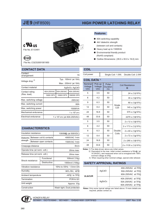
7;5A<6?@>?FEL<G B8I:?@D>G<B8M:EDI8:I ;8I8:E@B/IG=:5>07;6KF>27KF>26KF>28/Chmmhf ob^p0Onmebg^Ebf^glbhglEJIB@D<;@C<DH@EDH+L@G@D>;@8>G8C 8D;F:9E8G;B8MEJIUgbm?ffPDC LZrhnm 70Ghk ab`a bgknla ehZ]pbma ma^lm^Z]r2lmZm^\nkk^gm h_e^ll maZg 95B1ie^Zl^\ahhl^mri^J380Ug]^k ma^Zf[b^g\^pbma ]Zg`^khnl `Zl ebd^I 7S1SO 7hk NO 71pZla mb`am mri^bl k^\hff^g]^]@ie^Zl^m^lm ma^k^eZr bg k^Ze Ziieb\Zmbhgl3J_ma^Zf[b^g\^Zeehpl1]nlm ikhm^\m^]bl ik^_^k^gmbZeer k^\hff^g]^]390K F>bl Zg ^gobkhgf^gmZe _kb^g]er ikh]n\m3Pe^Zl^fZkdZ li^\bZe \h]^/:::0hk /::60pa^g hk]^kbg`3/::60lmZg]l RhIS \hfiebZgm pbma DZ]fbnf \hgmZ\m@/:::0lmZg]l _hk RhIS \hfiebZgm pbma DZ]fbnf2_k^^\hgmZ\m3DZ^Q]7W^e]bg`ib\mnk^l _hk KF>pbma mpblmbg`\hii^k pbk^3Pe^Zl^lahp p^e]bg`lmre^/B mh J 0Zg]ma^e^g`ma h_pbk^l pa^g hk]^kbg`3Pe^Zl^fZkdma^e^g`ma h_^Z\a pbk^_khf e^_m mh kb`am b_ma^e^g`ma bl ]b__^k^gm3/Chmmhf ob^p0H<I~OZY^NO^OWZ]Q*G<H<I~OZY^NO^Z[QY*SFTRFSFT SFTRFSFT Mhngmbg`T^kfbgZe Mhngmbg`T^kfbgZeMhngmbg`T^kfbgZe/\hgmZ\m \ehl^0/\hgmZ\m hi^g0/\hgmZ\m \ehl^0/\hgmZ\m hi^g0SFTRFSFT Mhngmbg`T^kfbgZe/\hgmZ\m \ehl^0/\hgmZ\m hi^g0SFTRFSFT Mhngmbg`T^kfbgZe/\hgmZ\m \ehl^0/\hgmZ\m hi^g0Mhngmbg`T^kfbgZe Mhngmbg`T^kfbgZeMhngmbg`T^kfbgZeH<I~OZY^NO^OWZ]Q*H<I~OZY^NO^OWZ]Q*H<I~OZY^NO^OWZ]Q*H<I~OZY^NO^Z[QY*H<I~OZY^NO^Z[QY*H<I~OZY^NO^Z[QY*KF>26KF>27KF>28KF>261R6KF>271R7KF>281R8KF>281R:KF>281R97;7Wbkbg`EbZ`kZf EJIB@D<;@C<DH@EDH+L@G@D>;@8>G8C 8D;F:9E8G;B8MEJIUgbm?ffPhlbmbo^iheZkbmrN^`Zmbo^iheZkbmrN^`Zmbo^iheZkbmr7;8=04/aA61RA;5501=05/aA71RA8550=06/aA61RA<5501=1-/aA71RA8:50=./aA61RA:5501=//aA71RA7:50=0/aA61RA:5501=1/aA71RA7:50=6/aA61RA8<501=.-/aA71RA6=:0=../aA61RA<5501=.//aA71RA8:50=.4/aA61RA;;501=.5/aA71RA8850=.6/aA61RA8;501=/-/aA71RA6=50=/2/aA61RA8=501=/3/aA71RA6>50=/4/aA61RA:5501=/5/aA71RA7:50=00/aA61RA95501=01/aA71RA7550=02/aA61RA;5501=03/aA71RA8550Smre^h_fZg`Zgbg langmDZ^Q]7Smre^G6mh G991ma^mab\dg^ll h_langm?aA6hk aA71R?k^lblmZg\^h_langm [^mp^^g B2C i v 1f 65,j=2=.0/aA61RA8>501=.1/aA71RA6>:0=/./aA61RA9:501=///aA71RA77:0=/6/aA61RA:5501=0-/aA71RA7:50=4/aA61RA8;501=5/aA71RA6=50=.2/aA61RA8:501=.3/aA71RA6<:0=/0/aA61RA:5501=/1/aA71RA7:50=0./aA61RA=5501=0//aA71RA9550EJIB@D<;@C<DH@EDH+L@G@D>;@8>G8C 8D;F:9E8G;B8MEJIUgbm?ffEbl\eZbf^kTabl ]ZmZla^^m bl _hk ma^\nlmhf^klx k^_^k^g\^3Bee ma^li^\b_b\Zmbhgl Zk^ln[c^\m mh \aZg`^pbmahnm ghmb\^3W^\hne]ghm ^oZenZm^Zee ma^i^k_hkfZg\^Zg]Zee ma^iZkZf^m^kl _hk ^o^kr ihllb[e^Ziieb\Zmbhg3Tanl ma^nl^k lahne][^bg Z kb`am ihlbmbhg mh \ahhl^ma^lnbmZ[e^ikh]n\m _hk ma^bk hpg Ziieb\Zmbhg3J_ma^k^bl Zgr jn^kr1ie^Zl^\hgmZ\m Ihg`_Z _hk ma^m^\agb\Ze l^kob\^3Ihp^o^k1bm bl ma^nl^kxl k^lihglb[bebmr mh ]^m^kfbg^pab\a ikh]n\m lahne][^nl^]hger3t XbZf^g Ihg`_Z Fe^\mkhZ\hnlmb\Dh31Lm]3Bee kb`aml h_Ihg`_Z Zk^k^l^ko^]37;9DZ^UOQ63R^eZr bl hg ma^yl^mz lmZmnl pa^g [^bg`k^e^Zl^]_khf lmh\d1pbma ma^\hglb]^kZmbhg h_lah\d kbl^g _khf mkZglbm Zg]k^eZr fhngmbg`1k^eZr phne][^\aZg`^]mh yk^l^mz lmZmnl1ma^k^_hk^1pa^g Ziieb\Zmbhg /\hgg^\mbg`ma^ihp^k lniier01ie^Zl^k^l^m ma^k^eZr mh yl^mz hk yk^l^mz lmZmnl hg k^jn^lm373Jg hk]^k mh fZbgmZbg yl^mz hk yk^l^mz lmZmnl1^g^k`bs^]ohemZ`^mh \hbe lahne]k^Z\a ma^kZm^]ohemZ`^1bfinel^pb]ma lahne][^:mbf^l fhk^maZg yl^mz hk yk^l^mz mbf^3Eh ghm ^g^k`bs^ohemZ`^mh yl^mz \hbe Zg]yk^l^mz \hbe lbfnemZg^hnler3Bg]Zelh ehg`^g^k`bs^]mbf^/fhk^maZg 6fbg0lahne][^Zohb]^]383Ta^m^kfbgZel h_k^eZr pbmahnm mpblm^]\hii^k pbk^\Zg ghm [^mbg2lhe]^k^]1\Zg ghm [^fho^]pbee_neer1fhk^ho^k mph m^kfbgZel \Zg ghm [^_bq^]Zm ma^lZf^mbf^3Smre^5:;k BAw937Smre^5:;26k BAw:37Smre^5<;k BAw937Smre^5<;26k BAw:37Smre^5<<k BAw937Smre^5<<26k BAw:37Smre^5<<27k BAw;37Dhgg^mhk lmre^Trib\Ze langm \hgg^\mbhg pZrlDZ^Q]7W^\Zg fZd^li^\bZe \hgg^\mbhg Z\\hk]bg`mh \nlmhkf^k.l k^jnbk^f^gm3Pe^Zl^ikhob]^nl pbmama^]kZpbg`1Zg]langm li^\b_b\Zmbhg Zg]\hgg^\mhk.l li^\b_b\Zmbbhg3GQXN\V760Jg \Zl^h_gh mhe^kZg\^lahpg bg hnmebg^]bf^glbhg?hnmebg^]bf^glbhg g 6ff1mhe^kZg\^lahne][^u537ff@hnmebg^]bf^glbhg l 6ffZg]g :ff1mhe^kZg\^lahne][^u538ff@hnmebg^]bf^glbhg l :ff1mhe^kZg\^lahne][^u539ff370Ta^mhe^kZg\^pbmahnm bg]b\Zmbg`_hk PDC eZrhnm bl ZepZrl u536ff3EJIB@D<;@C<DH@EDH+L@G@D>;@8>G8C 8D;F:9E8G;B8MEJIUgbm?ffSmre^h_fZg`Zgbg langmDZ^Q]7Smre^G6mh G991ma^mab\dg^ll h_langm?aA6hk aA71R?k^lblmZg\^h_langm [^mp^^g B2C i v 1f 65,j=1./aA61RA99501=1//aA71RA7750=10/aA61RA;5501=11/aA71RA8550。
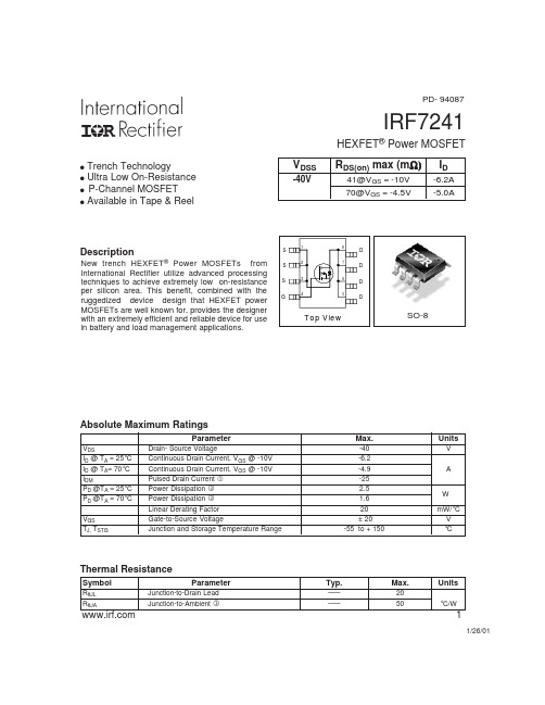
IRF7241中文资料
元器件交易网
IRF7241
C, Capacitance(pF)
5000
4000
Ciss
3000
VGS = 0V, f = 1 MHZ Ciss = Cgs + Cgd, Cds SHORTED Crss = Cgd Coss = Cds + Cgd
2000
1000 Coss
Parameter V(BR)DSS Drain-to-Source Breakdown Voltage ∆V(BR)DSS/∆TJ Breakdown Voltage Temp. Coefficient
RDS(on)
Static Drain-to-Source On-Resistance
VGS(th) gfs
1000 100
VGS TOP -15V
-10V -4.5V -3.7V -3.5V
-3.3V -3.0V BOTTOM -2.7V
10
1
0.1
0.01 0.1
-2.70V
20µs PULSE WIDTH TJ = 25 °C
1
10
100
-VDS, Drain-to-Source Voltage (V)
100.00
10.00
TJ = 150°C
2.0 ID = -6.2A 1.5
-ID, Drain-to-Source Current (Α)
1.00
0.10
0.01 2.5
TJ = 25°C
VDS = -25V 20µs PULSE WIDTH
3.0
3.5
4.0
4.5
5.0
-VGS, Gate-to-Source Voltage (V)
捷尔雷达产品说明书(0803版)

1. 液晶显示仪表技术规格………………………………………………………………………… 35 2. 壳体技术规格…………………………………………………………………………………… 35 3. 性能……………………………………………………………………………………………… 35 4. 现场信号显示器选型…………………………………………………………………………… 35
(见第8页) ● 导波管:导波管安装用来避免干扰回波。
(见第9页)
1 a
2 !
3.4 JERD801、JERD802的罐内安装 3.4.1 标准安装 ● 雷达天线不可向罐壁倾斜。 ● 为了使温度影响最小化,在对接法兰的连
屏蔽段
接处必须使用弹簧垫圈。 ● 杆式天线的雷达波发射处必须伸出安装短
管。 ● 垂直放置杆式天线,不要让雷达束指向罐
应 用 :存储或过程容器腐蚀性的液体、浆料、固体 比如:水液储罐,酸碱储罐,浆料储罐, 固体颗粒,小型储油罐
测 量 范 围 :20米 过 程 连 接 :法兰 介 质 温 度 :-40-150℃ 过 程 压 力 :-1.0-20bar 重 复 性 :± 2mm 精 度 :< 0.1% 频 率 范 围 :6.8GHz 防爆/防护等级:Exia II C T6/IP67 信 号 输 出 :4…20mA/HART(两线)
动一圈为止,在回波信号最佳位置定位。 Ⅳ) 在最优位置固定好法兰或拧紧螺纹,若有必要,更换密封圈。
回波信号示意图: 图一 正常的物位回波 图二 有虚假回波 db
100
50 →料位回波
0
0
20m
图一
db 100
50
→虚假干扰回波
→料位回波
HTRI中文手册

HTRI Exchanger 使用手册目录一、换热器的基础设计知识 ----------------------------------------------------------------------------------------------- - 2 -1.1 换热器的分类-------------------------------------------------------------------------------------------------------- - 2 -1.2换热器类型------------------------------------------------------------------------------------------------------------ - 3 -1.3换热器壳型及封头选取小结-------------------------------------------------------------------------------------- - 4 -二、IST HTRI的应用------------------------------------------------------------------------------------------------------ - 6 -2.1 方法类型(Method mode) ----------------------------------------------------------------------------------------- - 6 -2.2设计要求:------------------------------------------------------------------------------------------------------------ - 7 -2.3测量单位设置 -------------------------------------------------------------------------------------------------------- - 7 -2.4流体分配-Fluid Allocation -------------------------------------------------------------------------------------- - 8 -2. 5 HTRI主功能按钮 ------------------------------------------------------------------------------------------------ - 10 -2. 5. 1 Input-------------------------------------------------------------------------------------------------------- - 10 -2.5.2 Report ----------------------------------------------------------------------------------------------------- - 25 -2.5.3 Graphs------------------------------------------------------------------------------------------------------- - 25 -2.5.4 Drawings---------------------------------------------------------------------------------------------------- - 26 -2.5.5 Shells-in-Series -------------------------------------------------------------------------------------------- - 26 -三、输出结论 ------------------------------------------------------------------------------------------------------------------ - 26 -3.1一般结论------------------------------------------------------------------------------------------------------------- - 26 -3.1.1 总传热系数(裕量)不足的调节措施 ------------------------------------------------------------------ - 26 -3.1.2 壳程流速过高的调节措施 ----------------------------------------------------------------------------- - 27 -四、其他类型的换热器------------------------------------------------------------------------------------------------------ - 29 -4.1再沸器(Reboiler) -------------------------------------------------------------------------------------------------- - 29 -五、换热器的系统设计------------------------------------------------------------------------------------------------------ - 30 -5.1换热器的温度测量和控制方案--------------------------------------------------------------------------------- - 30 -5.2换热器系统设计要求 --------------------------------------------------------------------------------------------- - 32 -5.3 蒸发器系统设计--------------------------------------------------------------------------------------------------- - 33 -5.4 再沸器系统设计--------------------------------------------------------------------------------------------------- - 36 -5.5 冷凝器系统设计--------------------------------------------------------------------------------------------------- - 40 -5. 6 空冷系统设计 ----------------------------------------------------------------------------------------------------- - 43 -HTRI Exchanger 使用手册一、换热器的基础设计知识1.1 换热器的分类1.按作用原理和实现传热的方式分类(1)混合式换热器;(2)蓄热式换热器;(3)间壁式换热器其中间壁式换热器按传热面的形状和结构分类:(1)管壳式:固定管板式、浮头式、填料函式、U型管式(2)板式:板翅式、平板式、螺旋板式(3)管式:空冷器、套管式、喷淋管式、箱管式(4)液膜式:升降膜式、括板薄膜式、离心薄膜式(5)其他型式:板壳式、热管2.按换热器服务类型分类:(1)交换器(Exchanger): 在两侧流体间传递热量。
G941中文资料

3.7V 400mA Low Dropout RegulatorFeaturesDropout voltage typically 0.8V @ I O = 400mA Output current in excess of 400mA Output voltage accuracy +3%/-2% Quiescent current, typically 600µA Internal short circuit current limit Internal over temperature protectionGeneral DescriptionThe G940/G941 positive 3.7V voltage regulator fea-tures the ability to source 400mA of output current with a dropout voltage of typically 0.8V over the en-tire operating temperature range. A low quiescent current is provided over the entire output current range. The typical quiescent current is 0.6mA. Fur-thermore, the quiescent current is smaller when the regulator is in the dropout mode (V IN < 3.7V).Familiar regulator features such as over temperature and over current protection circuits are provided to prevent it from being damaged by abnormal operating conditions.Ordering InformationPIN OPTIONORDER NUMBERPACKAGE TYPE1 2 3G940T21U SOT 89 V OUT GND V IN G941T24U SOT 89 GND V IN V OUT G940T73U SOT 23 GND V OUT V IN*For other package types, pin options and package, please contact us at sales @ Order Number IdentificationType Pin Option TypePart NumberPACKAGE TYPEPIN OPTIONPACKINGT2 : SOT 89 1 2 3U & D : Tape & Reel D DirectionT6 : SOT 223 1 : V OUT GNDV IN T : Tube T7 : SOT 23 2 : V OUTV INGND B : Bag T8 : µTO92 3 : GND V OUT V IN4 : GND V INV OUT 5 : V IN GNDV OUT6 : V IN V OUT GNDTypical Application Package Type[Note 4] : Type of C OUTSOT 893µTO 92SOT 23、223V OUTAbsolute Maximum Ratings (Note 1)Input Voltage……………………………..……..…..…10V Power Dissipation Internally Limited ..(Note 2) Maximum Junction Temperature………….….…...150°C Storage Temperature Range…..…..…..-65°C ≤ T J ≤+150°C Lead Temperature, Time for Wave SolderingSOT 89, SOT23 Package….….…..……..…....260°C, 4s Continuous Power Dissipation (T A = + 25°C)SOT 23(1)…….…………………….….……….……...0.3W SOT 89(1)……………………….………..………..…0.42WNote (1): See Recommended Minimum Footprint.Operating Conditions (Note 1)Input Voltage………………………….…………….4V~7V Temperature Range………………….…0°C ≤ T J ≤125°CElectrical CharacteristicsV IN =5V, I O = 400mA, C IN = 1 µF, C OUT =10 µF, All specifications apply for T A = T J = 25°C. [Note 3]PARAMETER CONDITIONS MIN TYP MAX UNITSOutput Voltage Accuracy I O = 10mA -2 - +3 % Line Regulation V IN = 4V to 7V, I O = 50mA - 0.08 0.9 %/V Load Regulation I O = 10mA to 400mA - - 2.2 % Output Impedance 100mA DC and 100mA AC, fo = 120Hz - 100 - m ΩQuiescent Current V IN =5V - 0.6 - mA Ripple Rejection f i = 120 Hz, 1V P-P , Io = 100mA - 42 - dBI O = 400mA - 0.8 0.9 V Dropout Voltage I O = 100mA - 130 150 mV Short Circuit Current-0.76-AOver Temperature- 125 - °CNote 1: Absolute Maximum Ratings are limits beyond which damage to the device may occur. Operating Condi-tions are conditions under which the device functions but the specifications might not be guaranteed. For guaranteed specifications and test conditions see the Electrical Characteristics.Note 2: The maximum power dissipation is a function of the maximum junction temperature, T Jmax ; total thermal re-sistance, θJA , and ambient temperature T A . The maximum allowable power dissipation at any ambient tem-perature is T jmax -T A / θJA . If this dissipation is exceeded, the die temperature will rise above 130°C and ICwill go into thermal shutdown. For the G940/G941 in SOT 23 package, θJA is 350°C/W and in the SOT 89 package is 250°C/W (See Recommend Minimum Footprint). The safe operation in SOT 23 & SOT 89 package, it can see “Typical Performance Characteristics” (Safe Operating Area).Note3: Low duty pulse techniques are used during test to maintain junction temperature as close to ambient aspossible.Note4: The type of output capacitor should be tantalum or aluminum.DefinitionsDropout VoltageThe input/output Voltage differential at which the regulator output no longer maintains regulation against further reductions in input voltage. Measured when the output drops 100mV below its nominal value, dropout voltage is affected by junction temperature, load cur-rent and minimum input supply requirements.Line RegulationThe change in output voltage for a change in input voltage. The measurement is made under conditions of low dissipation or by using pulse techniques such that average chip temperature is not significantly af-fected.Load RegulationThe change in output voltage for a change in load current at constant chip temperature. The measure-ment is made under conditions of low dissipation or by using pulse techniques such that average chip tem-perature is not significantly affected.Maximum Power DissipationThe maximum total device dissipation for which the regulator will operate within specifications.Quiescent Bias CurrentCurrent which is used to operate the regulator chip and is not delivered to the load.Typical Performance Characteristics(V IN =5V, C IN =1µF, C OUT =10µF, T A =25°C, unless otherwise noted.)Ch1: Vout (offset=3.70V)Ch1: Iout (400mA/div)Ch2: Vin (offset=5.0V)Ch2: Vout (offset=3.70V)Iout=100mAGround Current vs. Load CurrentLine TransientLoad TransientOutput Voltage Accuracy vs. Load CurrentDropout Voltage vs. Load CurrentRecommend Minimum FootprintNote: V IN(max) <= 6.5VNote: V IN(max)<= 6.5VPackage InformationSOT-89 (T2) PackageDIMENSIONS IN MILLIMETERS DIMENSIONS IN INCHESSYMBOLSMIN NOM MAX MIN NOM MAXA 1.40 1.50 1.60 0.055 0.059 0.063 A1 0.80 1.04 ----- 0.031 0.041 ----- b 0.36 0.42 0.48 0.014 0.0160.048 b1 0.41 0.47 0.53 0.016 0.018 0.020 C 038 0.40 0.43 0.014 0.015 0.017 D 4.40 4.50 4.60 0.173 0.177 0.181 D1 1.40 1.60 1.75 0.055 0.062 0.069 HE ----- ----- 4.25 ----- ----- 0.167 E 2.40 2.50 2.60 0.094 0.098 0.102 e 2.90 3.00 3.10 0.114 0.118 0.122SOT-223 (T6) PackageMILLIMETERS INCHES SYMBOLSMIN MAX MIN MAXA 1.551.80 0.061 0.071 A1 0.02 0.12 0.0008 0.0047 B 0.60 0.80 0.024 0.031 B12.903.10 0.114 0.122 C 0.240.32 0.009 0.013 D 6.30 6.70 0.248 0.264 E 3.30 3.70 0.130 0.146 e 2.30 BSC0.090 BSC e1 4.60 BSC 0.181 BSC H 6.70 7.30 0.264 0.287 L 0.90 MIN0.036 MINL2 0.06 BSC 0.0024 BSCα0º 10º 0º 10º13°(4X)α(4X)SOT-23 (T7) PackageNote:1.Package body sizes exclude mold flash protrusions or gate burrs2.Tolerance ±0.1000 mm (4mil) unless otherwise specified3.Coplanarity: 0.1000mm4.Dimension L is measured in gage planeDIMENSIONS IN MILLIMETERSSYMBOLSMIN NOM MAXA 1.00 1.10 1.30 A10.00 ----- 0.10 A2 0.70 0.80 0.90 b 0.35 0.40 0.50 C 0.10 0.150.25 D 2.70 2.90 3.10 E 1.40 1.60 1.80 e ----- 1.90(TYP)----- H 2.60 2.80 3.00 L 0.37 ------ ----- θ1 1º 5º 9ºGMT Inc. does not assume any responsibility for use of any circuitry described, no circuit patent licenses are implied and GMT Inc. reserves the right at any time without notice to change said circuitry and specifications.SOT 23 Package OrientationSOT 89、223 Package Orientation。
ET1-24伊顿 (1)

当手车退出工作位置一定距离后,上下活门自动关闭并遮蔽住一次静触 头,见图3。同时由于上下活门不联动,在检修时可仅用挂锁锁定带电侧 的活门,对带电导体实现有效隔离,从而确保检修人员的安全。
其中, 为进线侧标识, 为出线侧标识, 为带电标识。
在未确定进线侧是否带电的情况下,禁止触及进线侧活门。
6.1
图4 母线隔室 1.1 母线隔室泄压盖板 2 分支母线 4 主母线 5 支持绝缘子 6 一次静触头盒
产品说明书 IB022008SC
2012年8月版
图6 继电器仪表室
装置在断路器隔室A和电缆终端联接室C内的加热器处于加热状态时,可 防止凝露的产生。但是,当断路器手车处于工作状态时,需及时切断加 热器电源,使其处于非加热状态。
图8 断路器手车在试验位置 在此位置,二次插头插接好,辅助回路接通,主回路仍未接通。
技术数据
开关柜主要技术数据见表1 表1 开关柜主要技术数据
序号 1 2 3 4 5 6
项目 额定电压 额定电流 额定短路开断电流 额定短路关合电流 4S热稳定电流(有效值) 外形尺寸
7
防护等级
单位 kV A kA kA kA mm
参数值
24
630
1250...1600...2000 2500...3150
手车 16
ET1-24开关柜所配手车根据用途不同,可分断路器手车、电压互感器手 车(PT车)、隔离手车等。相同规格的手车可实现百分之百的互换。手车 在柜内设有隔离/试验位置和工作位置(详见图7,图8,图9),每一位置均 设有定位装置,以保证联锁可靠,手车的操作必须按联锁防误操作程序 进行。手车采用的丝杆传动操动机构,设计合理、制造 精良、可有效确 保手车在推进推出时,动作轻巧、灵活、平稳。
EH4使用说明书

美国劳雷工业有限公司
目录
..................... 2 0.0 简介.............................................................................................................. .................... .................... ....................2 1.0 系统配件 .................................................................................................................... . ......................... 3 标准接收机配件................................................................................................................ ...................... 3 可选接收机组件 ................................................................................................................. . ...................3 2 发射机组件(400 统) 安系统) …….......................................................................... …. ……………………………….3. .2 发射机组件(5000安系统)……
PR4184通用单 双极性信号变送器 产品手册说明书

产品手册4184通用单/双极性信号变送器安全栅 | 通讯接口 | 多功能 | 隔离器 | 数显表No. 4184V103-CN自此序列号始: 191167001CommunicationDisplayI.S. InterfaceIsolationMultifunctionTemperature基于微处理器技术研发的 6 mm 隔离器,小巧精致、响应迅速、品质一流,以极低的总拥有成本为专用应用提供卓越性能和抗电磁干扰。
可水平或垂直安装,装置间无需间隙。
我们采用最严格的安全标准来检验产品,以期提供最安全的信号。
秉承创新精神,我们已经在 SIL 2 全面评估本质安全型接口方面取得了开创性成就,其既高效又经济,效果卓著,成效斐然。
模拟量和数字量本质安全栅种类齐全,同时提供多种输入输出。
这使得 PR 标准成为一项易于实施的现场检验标准。
在大型项目安装过程中,新背板方案大大简化安装和布线,且能与标准 DCS 系统无缝集成。
数显表系列以其灵活性和稳定性著称。
该设备系列几乎满足过程信号读数显示的所有需求,并具有通用的输入和供电能力。
无论哪种行业,无论环境条件何其苛刻,该设备均能实时测量过程值并提供用户友好型界面和值得信赖的继电器信号。
我们提供经济实惠、使用方便、面向未来的通讯接口,以便您能够访问所安装的 PR 产品。
所有接口均可拆卸,并带有屏幕和按钮,可以显示过程值/诊断值和对参数进行配置。
产品特定功能包括通过 Modbus 和蓝牙进行通讯,以及使用我们的便携式设备主管 (PPS) 应用程序进行远程访问,可用于 iOS 和 Android 。
单品为多功能系列产品,可涵盖大量现场应用,可轻而易举按照您的现场标准进行配置。
此种单品可适用多种应用方式,既节省安装和培训时间,又大大简化库存备件管理。
该设备专为长期信号精度高、功耗低、抗电噪声优异、编程简单而设计。
温度变送器和温度传感器系列产品,提供从温度测量点到系统控制一站式信号解决方案,从而在最大程度上保证信号的完整性。
NI 9219 四通道多功能测试模块说明书

DAT ASHEETNI 92194 AI, 100 S/s/ch Simultaneous, Universal Measurements•Spring-terminal connectivity•Support for Thermocouple (50 S/s/ch), RTD, Resistance,Full-Bridge, Half-Bridge, Quarter-Bridge, V oltage, and Current Measurements•V oltage and current excitation•250 V AC, CAT II, channel-to-channel isolationThe NI 9219 is a universal C Series module designed for multipurpose testing in any NI CompactDAQ or CompactRIO chassis. With the NI 9219, you can measure several signals from sensors such as strain gages, RTDs, thermocouples, load cells, and other poweredsensors. The channels are individually selectable, so you can perform a different measurement type on each of the four channels. Measurement ranges differ for each type of measurement and include up to ±60 V for voltage and ±25 mA for current.Kit ContentsAccessories • NI 9219• NI 9219 Getting Started Guide • Spring-Terminal Tool• NI 9972 Backshell Connector KitNI C Series OverviewNI provides more than 100 C Series modules for measurement, control, and communication applications. C Series modules can connect to any sensor or bus and allow for high-accuracy measurements that meet the demands of advanced data acquisition and control applications.•Measurement-specific signal conditioning that connects to an array of sensors and signals •Isolation options such as bank-to-bank, channel-to-channel, and channel-to-earth ground •-40 °C to 70 °C temperature range to meet a variety of application and environmental needs•Hot-swappableThe majority of C Series modules are supported in both CompactRIO and CompactDAQ platforms and you can move modules from one platform to the other with no modification. CompactRIOCompactRIO combines an open-embedded architecturewith small size, extreme ruggedness, and C Seriesmodules in a platform powered by the NI LabVIEWreconfigurable I/O (RIO) architecture. Each systemcontains an FPGA for custom timing, triggering, andprocessing with a wide array of available modular I/O tomeet any embedded application requirement. CompactDAQCompactDAQ is a portable, rugged data acquisition platformthat integrates connectivity, data acquisition, and signalconditioning into modular I/O for directly interfacing to anysensor or signal. Using CompactDAQ with LabVIEW, youcan easily customize how you acquire, analyze, visualize, andmanage your measurement data.2| | NI 9219 DatasheetSoftwareLabVIEW Professional Development System for Windows•Use advanced software tools for large project development•Generate code automatically using DAQ Assistant and InstrumentI/O Assistant•Use advanced measurement analysis and digital signal processing•Take advantage of open connectivity with DLLs, ActiveX, and .NETobjects•Build DLLs, executables, and MSI installersNI LabVIEW FPGA Module•Design FPGA applications for NI RIO hardware•Program with the same graphical environment used for desktop andreal-time applications•Execute control algorithms with loop rates up to 300 MHz•Implement custom timing and triggering logic, digital protocols, andDSP algorithms•Incorporate existing HDL code and third-party IP including Xilinx IPgenerator functions•Purchase as part of the LabVIEW Embedded Control and MonitoringSuiteNI LabVIEW Real-Time Module•Design deterministic real-time applications with LabVIEWgraphical programming•Download to dedicated NI or third-party hardware for reliableexecution and a wide selection of I/O•Take advantage of built-in PID control, signal processing, andanalysis functions•Automatically take advantage of multicore CPUs or setprocessor affinity manually•Take advantage of real-time OS, development and debuggingsupport, and board support•Purchase individually or as part of a LabVIEW suiteNI 9219 Datasheet| © National Instruments| 3NI 9219 CircuitryCH0CH3•The NI 9219 is channel-to-channel isolated.•Four 24-bit analog-to-digital converters (ADCs) simultaneously sample all four analog input channels.•The NI 9219 enables an excitation circuit for all input modes that require excitation.•The NI 9219 reconfigures the signal conditioning for each measurement type.Voltage Circuitry•The ADC measures voltage across the HI and LO terminals.•The NI 9219 has ±60 V, ±15 V, ±4 V, ±1 V, and ±125 mV voltage ranges.Current Circuitry4 | | NI 9219 DatasheetThe NI 9219 computes current from the voltage that the ADC measures across an internal shunt resistor.Thermocouple Circuitry•The NI 9219 uses the ±125 mV range of the ADC to return a voltage reading.•Each channel has a built-in thermistor for cold-junction compensation (CJC) calculations. 4-Wire Resistance and 4-Wire RTD CircuitryRTD/•The NI 9219 sources a current, which varies based on the resistance of the load, between the EX+ and EX- terminals. The NI 9219 computes measured resistance from theresulting voltage reading.•Lead wire resistance does not affect these measurement types because a negligible amount of current flows across the HI and LO terminals due to the high input impedance of the ADC.3-Wire RTD CircuitryRTDNI 9219 Datasheet| © National Instruments| 5•The NI 9219 sources a current, which varies based on the resistance of the load, between the EX+ and EX- terminals.•The NI 9219 compensates for lead wire resistance in hardware if all the lead wires have the same resistance.•The NI 9219 applies a gain of 2x to the voltage across the negative lead wire and the ADC uses this voltage as the negative reference to cancel the resistance error across the positive lead wire.2-Wire Resistance and Quarter-Bridge Circuitry•The NI 9219 sources a current, which varies based on the resistance of the load, between the HI and LO terminals.•The NI 9219 computes measured resistance from the resulting voltage reading.•2-Wire Resistance and Quarter-Bridge measurement types do not compensate for lead wire resistance.Full-Bridge Circuitry•The ADC reads the HI and LO inputs differentially.•The internal voltage excitation sets the input range of the ADC and returns voltage readings that are proportional to the excitation level. The internal excitation voltagevaries based on the resistance of the sensor.6| | NI 9219 DatasheetHalf-Bridge Circuitry•The HI input is referenced to EX-.•The internal voltage excitation sets the input range of the ADC and returns voltage readings that are proportional to the excitation level. The internal excitation voltagevaries based on the resistance of the sensor.Digital In Circuitry•The NI 9219 has a 60 V unipolar threshold that you can set in software.•The digital in measurement type is only supported in CompactRIO systems.Open Contact Circuitry•The NI 9219 sources a current between the HI and LO terminals and determines if the two terminals are open or closed based on the measured current through the terminals.•When the circuit is open, make sure no more than ±60 V is sourced across the switch.•The open contact measurement type is only supported in CompactRIO systems.NI 9219 Datasheet| © National Instruments| 7Timing ModesThe NI 9219 supports high-resolution, best 50 Hz rejection, best 60 Hz rejection, and high-speed timing modes. High-resolution timing mode optimizes maximum overall noise rejection and provides rejection of 50 Hz and 60 Hz noise . Best 50 Hz rejection optimizes 50 Hz noise rejection. Best 60 Hz rejection optimizes 60 Hz noise rejection. High-speed timing mode optimizes sample rate.NI 9219 SpecificationsThe following specifications are typical for the range -40 °C to 70 °C unless otherwise noted.Caution Do not operate the NI 9219 in a manner not specified in this document.Product misuse can result in a hazard. You can compromise the safety protectionbuilt into the product if the product is damaged in any way. If the product isdamaged, return it to NI for repair.Input CharacteristicsNumber of channels 4 analog input channelsADC resolution24 bitsType of ADC Delta-sigma (with analog prefiltering) Sampling mode SimultaneousType of TEDS supported IEEE 1451.4 TEDS Class 2 (Interface)8| | NI 9219 DatasheetTable 1. Input Ranges (Continued)Conversion time, all channelsNo channels configured as a thermocoupleHigh speed10 msBest 60 Hz rejection110 msBest 50 Hz rejection130 msHigh resolution500 msOne or more channels configured as a thermocoupleHigh speed20 msBest 60 Hz rejection120 msBest 50 Hz rejection140 msHigh resolution510 msOvervoltage protectionTerminals 1 and 2±30 V±60 VTerminals 3 through 6, across anycombinationInput impedanceV oltage and Digital In (±60 V, ±15 V,1 MΩ±4 V)Current< 40 ΩAll other measurement types>1 GΩNI 9219 Datasheet| © National Instruments| 9Table 2. Accuracy±1 °C typicalCold-junction compensation sensoraccuracy12-wire resistance accuracy assumes 0 Ω of lead wire resistance. 2-wire resistance accuracy depends on the lead wire resistance.10| | NI 9219 DatasheetTable 3. StabilityNI 9219 Datasheet| © National Instruments| 11Table 4. Input Noise in ppm of Range (Continued)Input bias current<1 nAINL±15 ppmCMRR (ƒin = 60 Hz)>100 dBNMRRBest 60 Hz rejection90 dB at 60 HzBest 50 Hz rejection80 dB at 50 HzHigh resolution65 dB at 50 Hz and 60 Hz2Excitation level is a characteristic and is not software-selectable.12| | NI 9219 DatasheetTable 5. Half-Bridge, Full-Bridge, Quarter-Bridge, Resistance, and RTD Excitation Level(Continued)MTBF384,716 hours at 25 °C; Bellcore Issue 2,Method 1, Case 3, Limited Part Stress Method Power RequirementsPower consumption from chassisActive mode750 mW maximumSleep mode25 µW maximumThermal dissipation (at 70 °C)Active mode625 mW maximumSleep mode25 µW maximumPhysical CharacteristicsIf you need to clean the module, wipe it with a dry towel.Tip For two-dimensional drawings and three-dimensional models of the C Seriesmodule and connectors, visit /dimensions and search by module number.Spring-terminal wiringGauge0.08 mm2 to 1.0 mm2 (28 AWG to 18 AWG)copper conductor wireWire strip length7 mm (0.28 in.) of insulation stripped from theend2Excitation level is a characteristic and is not software-selectable.NI 9219 Datasheet| © National Instruments| 13Temperature rating90 °C minimumWires per spring terminal One wire per spring terminalConnector securementSecurement type Screw flanges providedTorque for screw flanges0.2 N · m (1.80 lb · in.)Weight156 g (5.5 oz)Safety VoltagesConnect only voltages that are within the following limits.Channel-to-channelContinuous250 V AC, Measurement Category IIWithstand1,390 V AC, verified by a 5 s dielectricwithstand testChannel-to-earth groundContinuous250 V AC, Measurement Category IIWithstand2,300 V AC, verified by a 5 s dielectricwithstand testZone 2 hazardous locations applications in Europe60 VDC, Measurement Category IChannel-to-channel and channel-to-earth groundMeasurement Category I is for measurements performed on circuits not directly connected to the electrical distribution system referred to as MAINS voltage. MAINS is a hazardous live electrical supply system that powers equipment. This category is for measurements of voltages from specially protected secondary circuits. Such voltage measurements include signal levels, special equipment, limited-energy parts of equipment, circuits powered by regulated low-voltage sources, and electronics.Caution If using in Division 2 or Zone 2 hazardous locations applications, do notconnect the NI 9219 to signals or use for measurements within MeasurementCategories II, III, or IV.Note Measurement Categories CAT I and CAT O are equivalent. These test andmeasurement circuits are not intended for direct connection to the MAINS buildinginstallations of Measurement Categories CAT II, CAT III, or CAT IV. Measurement Category II is for measurements performed on circuits directly connected to the electrical distribution system. This category refers to local-level electrical distribution, such as that provided by a standard wall outlet, for example, 115 V for U.S. or 230 V for Europe.14| | NI 9219 DatasheetCaution Do not connect the NI 9219 to signals or use for measurements withinMeasurement Categories III or IV.Hazardous LocationsU.S. (UL)Class I, Division 2, Groups A, B, C, D, T4;Class I, Zone 2, AEx nA IIC T4Canada (C-UL)Class I, Division 2, Groups A, B, C, D, T4;Class I, Zone 2, Ex nA IIC T4Europe (ATEX) and International (IECEx)Ex nA IIC T4 GcSafety and Hazardous Locations StandardsThis product is designed to meet the requirements of the following electrical equipment safety standards for measurement, control, and laboratory use:•IEC 61010-1, EN 61010-1•UL 61010-1, CSA 61010-1•EN 60079-0:2012, EN 60079-15:2010•IEC 60079-0: Ed 6, IEC 60079-15; Ed 4•UL 60079-0; Ed 5, UL 60079-15; Ed 3•CSA 60079-0:2011, CSA 60079-15:2012Note For UL and other safety certifications, refer to the product label or the OnlineProduct Certification section.Electromagnetic CompatibilityThis product meets the requirements of the following EMC standards for sensitive electrical equipment for measurement, control, and laboratory use:•EN 61326 (IEC 61326): Class A emissions; Industrial immunity•EN 55011 (CISPR 11): Group 1, Class A emissions•AS/NZS CISPR 11: Group 1, Class A emissions•FCC 47 CFR Part 15B: Class A emissions•ICES-001: Class A emissionsNote For the standards applied to assess the EMC of this product, refer to theOnline Product Certification section.CE ComplianceThis product meets the essential requirements of applicable European Directives, as follows:•2014/35/EU; Low-V oltage Directive (safety)•2014/30/EU; Electromagnetic Compatibility Directive (EMC)•94/9/EC; Potentially Explosive Atmospheres (ATEX)NI 9219 Datasheet| © National Instruments| 15Online Product CertificationRefer to the product Declaration of Conformity (DoC) for additional regulatory compliance information. To obtain product certifications and the DoC for this product, visit / certification, search by model number or product line, and click the appropriate link in the Certification column.Shock and VibrationTo meet these specifications, you must panel mount the system.Operating vibrationRandom (IEC 60068-2-64) 5 g rms, 10 Hz to 500 HzSinusoidal (IEC 60068-2-6) 5 g, 10 Hz to 500 HzOperating shock (IEC 60068-2-27)30 g, 11 ms half sine; 50 g, 3 ms half sine;18 shocks at 6 orientations EnvironmentalRefer to the manual for the chassis you are using for more information about meeting these specifications.-40 °C to 70 °COperating temperature(IEC 60068-2-1, IEC 60068-2-2)-40 °C to 85 °CStorage temperature(IEC 60068-2-1, IEC 60068-2-2)Ingress protection IP40Operating humidity (IEC 60068-2-78)10% RH to 90% RH, noncondensing Storage humidity (IEC 60068-2-78)5% RH to 95% RH, noncondensing Pollution Degree2Maximum altitude2,000 mIndoor use only.Environmental ManagementNI is committed to designing and manufacturing products in an environmentally responsible manner. NI recognizes that eliminating certain hazardous substances from our products is beneficial to the environment and to NI customers.For additional environmental information, refer to the Minimize Our Environmental Impact web page at /environment. This page contains the environmental regulations and directives with which NI complies, as well as other environmental information not included in this document.16| | NI 9219 DatasheetWaste Electrical and Electronic Equipment (WEEE) EU Customers At the end of the product life cycle, all NI products must bedisposed of according to local laws and regulations. For more information abouthow to recycle NI products in your region, visit /environment/weee.电子信息产品污染控制管理办法(中国RoHS)中国客户National Instruments符合中国电子信息产品中限制使用某些有害物质指令(RoHS)。
FE2.1中文资料

FE2.1高速七端口USB2.0集线器控制芯片一引言FE2.1芯片是高度集成,高品质,高性能,低能耗,总体花费低的高速七端口USB2.0集线器解决方案。
FE2.1适应多样任务译码器(MMT)风格,借此达到最大的数据输出。
六个(而不是两个)非周期数据处理缓冲器被用来将潜在的传输干扰降至最低。
整个设计基于状态机控制原理,降低了相应延迟时间。
该芯片中没有使用微控制器。
为了保证高品质,整个芯片覆盖测试扫描链—包括高速模块(频率480MHz),所以在运行前可以检测所有逻辑组件。
芯片拥有特殊的自检建立模式,可以在封装和测试阶段测试高速、全速和低速模拟前端结束(AFE)元件。
通过使用0.18微米制造工艺和全面电源/时钟控制机制实现低功耗。
若无必要,芯片的大部分不会被锁住。
特点:■低功耗:□七个下行端口全部在高速模式工作时电流为155mA,□一个下行端口工作在高速模式下电流为66mA,■完全符合通用串行总线规范修订版2.0(USB2.0):□上传端口支持高速度(480MHz信)和全速(12MHZ)模式;□7下行端口支持高速(480MHz信),全速(12MHz)和低速(1.5MHz)模式;。
■集成USB2.0收发器;■集成上传1.5KΩ上拉电阻、下行1.5KΩ下拉电阻和串行电阻;■集成5V转3.3V和1.8V的电压调节器;■集成上电复位电路■集成12MHz的振荡器与反馈电阻和晶体负载电容;■集成12MHz转480MHz锁相回路;■多种任务译码器□一个任务译码器负责一个下行端口;□单任务译码器采用备用接口0,多任务译码器用备用接口1;□每个任务译码器可以处理64个开始分散任务、32个完全分散任务和6个无周期任务;■只支持自供电模式■主板配置选项——□成组或单独的电源控制模式选项;□全局、多模块或单模块过流保护选项;□配置可拆卸或不可拆卸下行设备;□选择下行端口数目;■电可擦可编程只读存储器配置选项——□供应商ID、产品ID和设备发行数量;□可拆卸或不可拆卸下行设备配置;□编号;□下行端口数目:■综合状态指标支持□标准下行端口状态指示灯(每个下行端口有绿色和琥珀色LED控制指示灯);□集线器工作/暂停状态LED指示灯;■支持微软Windows98SE/ME,2000,XP和Vista操作系统;■支持Mac OS 8.6及以上操作系统;■支持Linux 内核2.4.20及以上系统;封装:■64针脚LQFP(大小:10×10mm)■48针脚LQFP (大小: 7×7mm )框图(面积大小:10×10mm)64针脚封装引脚分配图48针脚封装引脚分配图引脚说明表格备注:1.OVCJ[7:2]针脚配有可选择的内部上拉电阻。
兰吉尔电子关口表说明书

H1 0244 1023 H1 0244 1024 H1 0244 1010 H1 0244 1015 A1 0244 1019 A1 0244 1042 TMS22/E 673C H1 0244 1007C
08/99 5/28
2.1
: -
r44
4 c
r14 4
ESSAILEC
: p(t)=u(t) I(t) W(t)=p(t) d(t)
ZU/ZV
p (SC- )
(Fref) 1/(F C)
ref
3.2
f9
:
f6
ZU(f9)
ESSAILEC
3.2.1 H1 0244 10ZH a C
f6 f9 r13/r14/r44
ZU/ZV 68HCII
r441
f6
ASIC MGA3
r13/r14/r44
ZU100 3
:
(A:d)
(R:d)
3
(A:t)
(R:e)
ZU200
RS485 (DIN19244)
IEC870-5 FAG
2.2
f9.11 1 f9.12 2
( ESSAILEC ) ( ESSAILEC )
ZU100/ZU200/ZV200
08/99
H1 0244 10ZH a C
6/28
3.1
fR
f9:
ESSAILEC
7.2
ZMU202C.4cr14r41f9
/
3x230/400V,5A
120%
50HZ
i=0.25kWh/imp
220V,50Hz
(
8
9)
RUZ-092424中文资料

40 20 0
121515 241515
Efficiency %
20 0
0%
20%
40%
60%
80%
100%
0%
20%
40%
60%
80%
100%
Total Output current (%)
Total Output current (%)
Deviation / Load
25.000 20.000 25.000 20.000
元器件交易网
Features
Unregulated Converters
● ● ● ● ● ● ● ●
Dual Output from a Single Input Rail Input/Output Isolation 1kVDC Output/Output Isolation 1kVDC Power Sharing on Outputs UL94V-0 Package Material Toroidal Magnetics No Extern. Components Required Efficiency to 85%
ECONOLINE
DC/DC-Converter
RUZ Series
Selection Guide
Part Number SIP 7 RUZ-xx3.33.3 RUZ-xx0505 RUZ-xx0509 RUZ-xx0512 RUZ-xx0515 RUZ-xx0909 RUZ-xx1212 RUZ-xx1515 RUZ-xx2424 xx = Input Voltage Input Voltage (VDC) 5, 9, 12, 24 5, 9, 12, 24 5, 9, 12, 24 5, 9, 12, 24 5, 9, 12, 24 5, 9, 12, 24 5, 9, 12, 24 5, 9, 12, 24 5, 9, 12, 24 Output Voltage (V1VDC) 3.3 5 5 5 5 9 12 15 24 Output Voltage (V2VDC) 3.3 5 9 12 15 9 12 15 24 Output Current (mA) 303/303 200/200 200/111 200/84 200/66 111/111 84/84 66/66 42/42 Efficiency (%) 70 70-82 70-82 70-82 70-82 82-84 82-84 82-84 80-85
ES1J中文资料(Won-Top Electronics)中文数据手册「EasyDatasheet - 矽搜」

to part number above. For example, ES1A-T3-LF.
-1.0A
5 / 10ns的/厘米设定的时基
芯片中文手册,看全文,戳
标识信息
WTE ES1x
阴极
WTE ES1x x
=极性带 =制造商的标志 =设备号 = A,B,C,D,E,G或按J
推荐的足迹
0.050 MIN (1.27 MIN)
0.083 MAX (2.11 MAX)
0.058 MIN (1.47 MIN)
0
0 25 50 75 100 125 150 175
T L ,焊接温度 图. 1正向电流降额曲线
( ° C)
30
Pulse width 8.3 ms single half-sine-wave
(JEDEC method)
,正F 向电流(A) I 0.01
0 0.2 0.4 0.6 0.8
VF,正向电压(V) 图. 2典型正向特性
0.95
1.25
5.0 500
35
10
35
-65到+150
1.7
V
µA
nS pF °C/W °C
注:1.测量与我
F = 0.5A, I R = 1.0A, I rr = 0.25A.见图5.
2.测得1.0 MHz和应用4.0 V DC反向电压.
3.安装在交媾后董事会8.0毫米
2 土地面积.
芯片中文手册,看全文,戳
外箱尺寸
长×宽×高(mm)
HS-2410Manual_Chinese
Hydrosense2410 水中油在线分析仪用户手册Arjay Engineering Ltd.Oakville (Toronto), Canada, L6H 6C9Arjay- China Customer Care Center 加拿大亚捷(中国)技术服务中心Web-Site:E-mail:arjaybj@Tel : 086-10-68998096Fax :086-10-68998213目录规格1 综述 (4)1.1 特点 (4)1.2 说明 (4)1.3 影响精度的因素 (4)1.4 日常清洁 (6)2 安装 (7)2.1 仪器安装注意事项 (7)2.2 符号与术语 (8)2.3 安装单元 (9)2.4 电源连接(交流电源) (9)2.5 电气安装 (10)3 初始启动和设置 (11)3.1 数字输入说明 (11)3.2 开机显示 (12)3.3 系统功能设置 (12)3.3.1 操作量程设置 (12)3.3.2 4-20mA 电流正/反向输出确认 (13)3.3.3 继电器报警值设置 (13)3.3.4 继电器延时 (13)3.3.5 继电器吸合与释放 (13)4 仪器标定 (14)4.1 准备工作 (14)4.2 标定 (14)4.2.1 自动标定 (14)4.2.2 手动标定 (15)4.2.3 增益设置 (15)4.2.4 灯强度及温度补偿设置 (16)4.2.5 选择标定曲线 (16)5 操作和诊断 (16)5.1 放大信号 (16)5.2 原始信号 (16)5.3 诊断 (16)5.4 最大值/最小值 (17)5.5 设置 (17)6 参数设置 (18)7 配制标样 (19)8 定期检测和维护 (20)8.1 定期检测 (20)8.2 清洁 (20)8.3 更换汞灯 (21)规格电源:220V AC;50Hz,150V A显示:四行LED显示,PPM浓度值及输出量与满刻度的条形图报警装置:两个继电器,负载能力:5 A,250V AC。
DFU400 使用说明书

0XJ 465 160第 3 页共 63 页旧底图总号底图总号签字日期z 回校指示和接收外部控制及开关设备所发报警信号;z 模拟量的测量;z 通过电触发信号产生的内部时钟同步;z 通过光触发信号产生的内部时钟同步。
1.3.2 串行接口z 与主控站通信;z 配置参数,调试和就地控制;z 下载系统固件。
2 技术参数2.1 基本数据2.1.1 开关量输入a)输入通道个数: 40;b)额定电压: 24 VDC, 110 VDC, 220 VDC 可选;c)电压范围: 额定电压的±20%;d)信号电平/电压范围:低电平: 0 V ∼ 额定电压的40% ;高电平: 额定电压的60% ∼ 额定电压的120%。
e)输入死区时间:1 ms ∼ 2550 s可配置;f)输入滤波时间:1 ms ∼ 2550 s可配置;g)每个通道的功耗: 1.1 W (2.5 mA 220 VDC);h)电气隔离: 光耦;i)连接: 插入式连接, 4 mm2端子。
2.1.2 开关量输出a)输出通道个数: 24, 每个通道2个空接点(触点), 每两个通道一个公共回路;b)输出接点电压:选项1: 110 VDC/175 VAC(带触点防护);选项2: 220 VDC/250 VAC(带触点防护);选项3: 220 VDC/250 VAC(无触点防护)。
c)最大开关电流: 15 A 最大4 s (通道1到通道22);25 A 最大4 s (通道23到通道24);d)最大持续电流: 8 A (通道1到通道22);10 A (通道23到通道24);e)切换容量: 50 W∼270 W (通道1到通道22);35 W∼500 W (通道23到通道24);f)电气隔离: 继电器;g)连接: 插入式连接, 4 mm2端子。
2.1.3 模拟量输入a)输入通道个数: 8;0XJ 465 160第 4 页共 63 页旧底图总号底图总号签字日期b)额定值: 20 mA,10 V可选;c)标幺值: 10 mA,5 V为100% ;d)测量误差: 0.5%额定值;e)输入滤波器的死区时间: 0.8 ms(20 mA 输入), 50 µF(10 V 输入);f)每个通道功耗: 20 mW (电流输入) / 2 mW (电压输入);g)每个电压/电流通道输入阻抗: 50 kΩ(电压输入)/200 Ω(电流输入);h)电气隔离: 通过外部连接的变送器或互感器;i)连接: 插入式连接, 2.5 mm2端子。
EH4说明书

一、EH4是全新概念的电导率张量测量仪通常意义下的电探仪,指的是交、直流电阻率剖面仪。
这两种方法都是有源测量方法,需要向地下直接供电,并且随着测量深度加大,电极布线和供电量都不断增加,野外劳动强度大,效率低。
另一方面,尽管这两种方法都属于有源电探,但采集到的视电阻率值都属于标量范畴,对辨别地下二度体异常的走向无能为力。
大地电磁同属于电探,但它是无源测量。
利用天然电磁场,虽然避免了大电流供电,但天然电磁场不稳定,而且某些频段先天不足,干扰强,讯号弱。
参看(图1)大地电磁场水平分量频谱展示图。
它反映了天然电磁场与人文电磁场的分布情况。
在1Hz左右,无论电场和磁场都是低谷;在1000Hz处磁场几近寂静,电场有一低谷。
在几十赫兹到104Hz范围内,人文活动的电磁场干扰特别严重。
这些特点决定了大地电磁法只适合于采集较低频率。
通常观测时间长,分辨率较低,适合解决深层宏观问题。
所以尽管电探方法起源最早,几十年来,由于以上的局限性,一直阻碍它的发展。
几十年来,1000米以内,几百米上下,正是人类经济、文明活动在地壳上层最活跃的深度。
其它物探方法,如地震勘探法,自40~50年代之后都开始大展身手,而浅、中深度范围的电探则相对寂寞冷落,处于陪衬地位。
也正是这种现状激发了国内外众多的科学家和仪器制造商不断研制开发新的电探仪器,寻找新的电探方法。
96年中下旬,由美国以研制大地电磁仪器而闻名的EMI公司和以制造高分辨率地震仪著名的Geometrics公司联合研制出EH4。
这是全新概念的电导率张量测量仪。
它利用大地电磁的测量原理,但配置了特殊的人工电磁波发射源。
这种发射源的天线是一对十字交叉的天线,组成X、Y两个方向的磁偶极子,轻便而且只用于普通汽车电瓶供电,发射率从500Hz到100KHz,专门用来弥补大地电磁场的寂静区和几百赫兹附近的人文电磁干扰谐波(见图1)。
仪器用反馈式高灵敏度低噪音磁棒和特制的电极,分别接收X、Y两个方向的磁场和电场。
北京捷尔斯全套图纸

电梯电气原理图目录主控制回路 -------------------------1 电源控制回路---------------------------------2主控制器回路 ------------------------3 轿厢控制器回路-------------------------------4指令控制回路-------------------------5 通讯控制回路---------------------------------6召唤、显示控制回路-------------------7 检修控制回路----------------------------------8安全及制动回路----------------------9 门机控制回路---------------=-----------------10电梯电气系统图 ---------------------11 机房接线图----------------------------------12操纵盘接线图------------------------13 轿顶接线图----------------------------------14 随行电缆接线图---------------------15 井道电缆接线图1-----------------------------16井道分支电缆布线图-----------------17 厅门锁电缆布线图-----------------------------18道呼梯电缆布线图-------------------19 元件布置图-----------------------------------20 Beijing in, the electrical machinery Co., LTDJLS-ATV电气系统代号说明1第一章 微机主板功能介绍一、 液晶显示屏及操作按键微机自带调试操作器,用于设置微机工作参数或监视微机工作数据。
多功能电力仪表PD194Z-2S4 2S4D 2S4+用户手册说明书

多功能电力仪表用户手册适用型号:PD194Z-2S4/2S4D/2S4+PD194Z-2S9/2S9D/2S9+PD194Z-2S7/2S7+PD194E-2S4/2S4+/2S9/2S9+/2S7/2S7+ PD194Z-9S4/9S4+/9S9/9S9+/9S7/9S7+ PD194E-9S4/9S4+/9S9/9S9+/9S7/9S7+安全须知感谢您选择江苏斯菲尔电气股份有限公司研发的产品,为了方便您选购和安全、正确、高效的使用本产品,请仔细阅读本手册并在使用时务必注意以下几点。
注意CAUTION:◆该装置必须有专业人员进行安装与检修◆在对该装置进行任何内部或外部操作前、必须切断输入信号和电源◆始终使用合适的电压检测装置来确定仪表各部位无电压◆提供给该装置的电参数需在额定范围内下述情况会导致装置损坏或装置工作的异常:◆辅助电源电压超范围◆配电系统频率超范围◆电流或电压输入极性不正确◆带电拨通信插头◆未按要求连接端子连线本手册可以在本公司的主页上下载到最新版本,同时也提供一些相应的测试软件下载。
如果您需要电子版用户手册可以向本公司的技术服务部门索取。
目录1产品简介 (1)1.1概述 (1)1.2选型 (1)2技术规格 (4)2.1技术参数 (4)2.2测量参数 (6)3安装与接线 (7)3.1尺寸 (7)3.2安装 (8)3.3接线 (9)4操作 (12)4.1面板 (12)4.2显示 (13)4.2.1电量显示 (13)4.3设置 (17)4.3.1系统设置 (21)4.3.2信号输入设置 (22)4.3.3通信设置 (23)4.3.4继电器输出设置 (24)4.3.5模拟量输出设置 (25)5功能 (26)5.1需量记录 (26)5.2电能脉冲输出 (26)5.3开关量输入 (27)5.4继电器输出 (28)5.5模拟量输出 (29)5.6模拟量输入 (30)6通信 (31)6.1物理层 (31)6.2通信协议MODBUS-RTU (31)6.3报文指令格式 (32)6.4数据格式 (38)附录MODBUS-RTU通信寄存器信息表 (39)一次电网数据 (39)二次电网数据 (40)生产信息 (41)参数设置 (41)1产品简介1.1概述PD194系列多功能电力仪表是针对电力智能监控和电能计量需求设计,能测量三相电网中的常用电力参数,三相电压、电流、功率、功率因数、频率、电能、需量等。
江苏斯菲尔电气 H 系列液晶多功能谐波表 说明书
H系列液晶多功能谐波表用户手册V 1.0本手册适用于以下型号的产品PD194E-9HYPD194Z-9HY江 苏 斯 菲 尔 电 气 股 份 有 限 公 司JIANGSU SFERE ELECTRIC CO., LTDH系列液晶多功能谐波表用户手册 v1.0感谢您选择江苏斯菲尔电气股份有限公司研发的H系列液晶多功能谐波表,为了方便您安全、正确、高效的使用本装置,请仔细阅读本说明书并在使用时务必注意以下几点。
注意CAUTION:该装置必须由专业人员进行安装与检修在对该装置进行任何内部或外部操作前、必须隔离输入信号和电源始终使用合适的电压检测装置来确定仪表各部位有无电压提供给该装置的电参数需在额定范围内下述情况会导致装置损坏或装置工作的异常:辅助电源电压超范围配电系统频率超范围电流或电压输入极性不正确带电拔插通信插头未按要求连接端子连线本手册可以在本公司的主页上下载到最新版本,同时也提供一些相应的测试软件下载。
如果您需要备份纸质用户手册可以向本公司的技术服务部门申请。
(具体公司网址、联系电话等见封底)目 录一、产品简介 (2)1.1引用标准 (2)1.2产品概述 (2)二、技术参数 (2)三、安装与接线 (3)3.1仪表尺寸 (3)3.2安装方式 (4)3.3接线端子功能说明 (4)3.4输入信号线连接 (5)四、菜单显示与编程 (6)4.1面板说明 (6)4.2菜单介绍与操作 (6)4.2.1电量显示 (6)4.2.2电能显示 (9)4.2.3谐波显示 (10)4.2.4编程设置 (12)4.3编程操作方法 (14)4.3.1系统设置 (14)4.3.2输入设置 (14)4.3.3通讯设置 (15)4.3.4报警设置 (15)4.3.5变送设置 (16)五、功能模块 (16)5.1通讯 (16)5.1.1物理层 (16)5.1.2通讯协议 MODBUS-RTU (16)5.1.3报文格式指令 (18)5.2电能脉冲输出 (20)5.3开关量输入 (21)5.4开关量输出 (21)5.5变送输出 (23)六、常见问题及解决办法 (26)6.1关于通讯 (26)6.2关于U I P Q等测量不准确 (26)6.3关于电能走字不准确 (26)6.4仪表不亮 (26)6.5仪表不响应任何操作 (26)6.6其它异常情况 (27)一、产品简介1.1引用标准引用国家标准GB/T 17883-1999 0.2S 级和0.5S 级静止式交流有功电度表 GB/T 17882-1999 2级和3级静止式交流无功电度表 DL/T 614-1997 多功能电能表GB/T17626-1998 电磁兼容 试验和测量技术 相应国际标准IEC 62053-22:2003 电量测量设备(交流)-特殊要求-第22部分:静态电度表(0.2S 和0.5S) IEC 62053-23:2003 电量测量设备(交流)-特殊要求-第23部分:静态无功表(2级和3级) IEC 61010-1:2001 测量、控制以及实验室用电气设备的安全要求-第1部分:一般要求 IEC 61000-2-11 电磁兼容性(EMC)-第2-11部分 IEC 60068-2-30 环境测试-第2-30部分1.2 产品概述H 系列液晶多功能谐波表可测量各种常用电力参数、有无功电能、谐波含量,并具有数字通讯、越限报警、监测开关状态、电能脉冲输出和模拟量变送输出等功能。
- 1、下载文档前请自行甄别文档内容的完整性,平台不提供额外的编辑、内容补充、找答案等附加服务。
- 2、"仅部分预览"的文档,不可在线预览部分如存在完整性等问题,可反馈申请退款(可完整预览的文档不适用该条件!)。
- 3、如文档侵犯您的权益,请联系客服反馈,我们会尽快为您处理(人工客服工作时间:9:00-18:30)。
7;5A<6?@>?FEL<G B8I:?@D>G<B8M:EDI8:I ;8I8:E@B/IG=:5>07;6KF>27KF>26KF>28/Chmmhf ob^p0Onmebg^Ebf^glbhglEJIB@D<;@C<DH@EDH+L@G@D>;@8>G8C 8D;F:9E8G;B8MEJIUgbm?ffPDC LZrhnm 70Ghk ab`a bgknla ehZ]pbma ma^lm^Z]r2lmZm^\nkk^gm h_e^ll maZg 95B1ie^Zl^\ahhl^mri^J380Ug]^k ma^Zf[b^g\^pbma ]Zg`^khnl `Zl ebd^I 7S1SO 7hk NO 71pZla mb`am mri^bl k^\hff^g]^]@ie^Zl^m^lm ma^k^eZr bg k^Ze Ziieb\Zmbhgl3J_ma^Zf[b^g\^Zeehpl1]nlm ikhm^\m^]bl ik^_^k^gmbZeer k^\hff^g]^]390K F>bl Zg ^gobkhgf^gmZe _kb^g]er ikh]n\m3Pe^Zl^fZkdZ li^\bZe \h]^/:::0hk /::60pa^g hk]^kbg`3/::60lmZg]l RhIS \hfiebZgm pbma DZ]fbnf \hgmZ\m@/:::0lmZg]l _hk RhIS \hfiebZgm pbma DZ]fbnf2_k^^\hgmZ\m3DZ^Q]7W^e]bg`ib\mnk^l _hk KF>pbma mpblmbg`\hii^k pbk^3Pe^Zl^lahp p^e]bg`lmre^/B mh J 0Zg]ma^e^g`ma h_pbk^l pa^g hk]^kbg`3Pe^Zl^fZkdma^e^g`ma h_^Z\a pbk^_khf e^_m mh kb`am b_ma^e^g`ma bl ]b__^k^gm3/Chmmhf ob^p0H<I~OZY^NO^OWZ]Q*G<H<I~OZY^NO^Z[QY*SFTRFSFT SFTRFSFT Mhngmbg`T^kfbgZe Mhngmbg`T^kfbgZeMhngmbg`T^kfbgZe/\hgmZ\m \ehl^0/\hgmZ\m hi^g0/\hgmZ\m \ehl^0/\hgmZ\m hi^g0SFTRFSFT Mhngmbg`T^kfbgZe/\hgmZ\m \ehl^0/\hgmZ\m hi^g0SFTRFSFT Mhngmbg`T^kfbgZe/\hgmZ\m \ehl^0/\hgmZ\m hi^g0Mhngmbg`T^kfbgZe Mhngmbg`T^kfbgZeMhngmbg`T^kfbgZeH<I~OZY^NO^OWZ]Q*H<I~OZY^NO^OWZ]Q*H<I~OZY^NO^OWZ]Q*H<I~OZY^NO^Z[QY*H<I~OZY^NO^Z[QY*H<I~OZY^NO^Z[QY*KF>26KF>27KF>28KF>261R6KF>271R7KF>281R8KF>281R:KF>281R97;7Wbkbg`EbZ`kZf EJIB@D<;@C<DH@EDH+L@G@D>;@8>G8C 8D;F:9E8G;B8MEJIUgbm?ffPhlbmbo^iheZkbmrN^`Zmbo^iheZkbmrN^`Zmbo^iheZkbmr7;8=04/aA61RA;5501=05/aA71RA8550=06/aA61RA<5501=1-/aA71RA8:50=./aA61RA:5501=//aA71RA7:50=0/aA61RA:5501=1/aA71RA7:50=6/aA61RA8<501=.-/aA71RA6=:0=../aA61RA<5501=.//aA71RA8:50=.4/aA61RA;;501=.5/aA71RA8850=.6/aA61RA8;501=/-/aA71RA6=50=/2/aA61RA8=501=/3/aA71RA6>50=/4/aA61RA:5501=/5/aA71RA7:50=00/aA61RA95501=01/aA71RA7550=02/aA61RA;5501=03/aA71RA8550Smre^h_fZg`Zgbg langmDZ^Q]7Smre^G6mh G991ma^mab\dg^ll h_langm?aA6hk aA71R?k^lblmZg\^h_langm [^mp^^g B2C i v 1f 65,j=2=.0/aA61RA8>501=.1/aA71RA6>:0=/./aA61RA9:501=///aA71RA77:0=/6/aA61RA:5501=0-/aA71RA7:50=4/aA61RA8;501=5/aA71RA6=50=.2/aA61RA8:501=.3/aA71RA6<:0=/0/aA61RA:5501=/1/aA71RA7:50=0./aA61RA=5501=0//aA71RA9550EJIB@D<;@C<DH@EDH+L@G@D>;@8>G8C 8D;F:9E8G;B8MEJIUgbm?ffEbl\eZbf^kTabl ]ZmZla^^m bl _hk ma^\nlmhf^klx k^_^k^g\^3Bee ma^li^\b_b\Zmbhgl Zk^ln[c^\m mh \aZg`^pbmahnm ghmb\^3W^\hne]ghm ^oZenZm^Zee ma^i^k_hkfZg\^Zg]Zee ma^iZkZf^m^kl _hk ^o^kr ihllb[e^Ziieb\Zmbhg3Tanl ma^nl^k lahne][^bg Z kb`am ihlbmbhg mh \ahhl^ma^lnbmZ[e^ikh]n\m _hk ma^bk hpg Ziieb\Zmbhg3J_ma^k^bl Zgr jn^kr1ie^Zl^\hgmZ\m Ihg`_Z _hk ma^m^\agb\Ze l^kob\^3Ihp^o^k1bm bl ma^nl^kxl k^lihglb[bebmr mh ]^m^kfbg^pab\a ikh]n\m lahne][^nl^]hger3t XbZf^g Ihg`_Z Fe^\mkhZ\hnlmb\Dh31Lm]3Bee kb`aml h_Ihg`_Z Zk^k^l^ko^]37;9DZ^UOQ63R^eZr bl hg ma^yl^mz lmZmnl pa^g [^bg`k^e^Zl^]_khf lmh\d1pbma ma^\hglb]^kZmbhg h_lah\d kbl^g _khf mkZglbm Zg]k^eZr fhngmbg`1k^eZr phne][^\aZg`^]mh yk^l^mz lmZmnl1ma^k^_hk^1pa^g Ziieb\Zmbhg /\hgg^\mbg`ma^ihp^k lniier01ie^Zl^k^l^m ma^k^eZr mh yl^mz hk yk^l^mz lmZmnl hg k^jn^lm373Jg hk]^k mh fZbgmZbg yl^mz hk yk^l^mz lmZmnl1^g^k`bs^]ohemZ`^mh \hbe lahne]k^Z\a ma^kZm^]ohemZ`^1bfinel^pb]ma lahne][^:mbf^l fhk^maZg yl^mz hk yk^l^mz mbf^3Eh ghm ^g^k`bs^ohemZ`^mh yl^mz \hbe Zg]yk^l^mz \hbe lbfnemZg^hnler3Bg]Zelh ehg`^g^k`bs^]mbf^/fhk^maZg 6fbg0lahne][^Zohb]^]383Ta^m^kfbgZel h_k^eZr pbmahnm mpblm^]\hii^k pbk^\Zg ghm [^mbg2lhe]^k^]1\Zg ghm [^fho^]pbee_neer1fhk^ho^k mph m^kfbgZel \Zg ghm [^_bq^]Zm ma^lZf^mbf^3Smre^5:;k BAw937Smre^5:;26k BAw:37Smre^5<;k BAw937Smre^5<;26k BAw:37Smre^5<<k BAw937Smre^5<<26k BAw:37Smre^5<<27k BAw;37Dhgg^mhk lmre^Trib\Ze langm \hgg^\mbhg pZrlDZ^Q]7W^\Zg fZd^li^\bZe \hgg^\mbhg Z\\hk]bg`mh \nlmhkf^k.l k^jnbk^f^gm3Pe^Zl^ikhob]^nl pbmama^]kZpbg`1Zg]langm li^\b_b\Zmbhg Zg]\hgg^\mhk.l li^\b_b\Zmbbhg3GQXN\V760Jg \Zl^h_gh mhe^kZg\^lahpg bg hnmebg^]bf^glbhg?hnmebg^]bf^glbhg g 6ff1mhe^kZg\^lahne][^u537ff@hnmebg^]bf^glbhg l 6ffZg]g :ff1mhe^kZg\^lahne][^u538ff@hnmebg^]bf^glbhg l :ff1mhe^kZg\^lahne][^u539ff370Ta^mhe^kZg\^pbmahnm bg]b\Zmbg`_hk PDC eZrhnm bl ZepZrl u536ff3EJIB@D<;@C<DH@EDH+L@G@D>;@8>G8C 8D;F:9E8G;B8MEJIUgbm?ffSmre^h_fZg`Zgbg langmDZ^Q]7Smre^G6mh G991ma^mab\dg^ll h_langm?aA6hk aA71R?k^lblmZg\^h_langm [^mp^^g B2C i v 1f 65,j=1./aA61RA99501=1//aA71RA7750=10/aA61RA;5501=11/aA71RA8550。
