AVR系列ISP方法
单片机程序烧录方法

单片机程序烧录方法
单片机程序烧录方法通常有以下几种:
1. ISP(In-System Programming)烧录法:使用一根数据线将电脑与单片机相连,通过编程软件将程序下载到单片机中。
这种方法适用于支持ISP烧录的单片机,如AVR系列、STC系列等。
2. ICSP(In-Circuit Serial Programming)烧录法:将单片机取下,使用专用的编程器将程序下载到单片机中,再将单片机插回电路板。
这种方法适用于不支持ISP烧录的单片机,如PIC系列。
3. 载波烧录法:将单片机放在载波上,通过载波烧录机将程序下载到单片机中。
这种方法适用于大批量生产中的单片机烧录。
需要注意的是,不同类型的单片机使用的烧录方法可能不同,而且不同型号的单片机可能需要不同的烧录软件和编程器。
在进行单片机程序烧录之前,需要了解所使用单片机的烧录方法和要使用的烧录工具,以确保正确地烧录程序到单片机中。
AVR单片机ISP下载线制作方法

AVR单片机ISP下载线
AVR单片机可以使用串行在线编程(ISP)方式将程序写入,即可直接在电路板上进行程序的烧写和修改,所需的装置就是一根ISP下载线。
下面介绍一编程线使用计算机并口对单片机编程,不仅支持AVR单片机,也支持对51单片机中的AT89S系系的单片机编程。
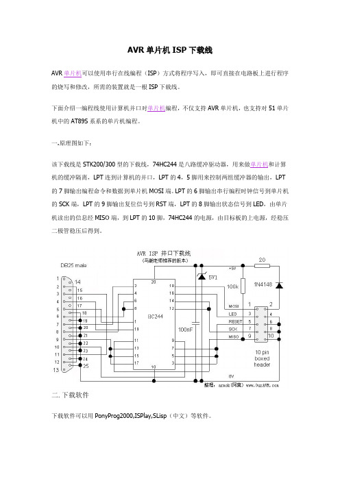
一.原理图如下:
该下载线是STK200/300型的下载线,74HC244是八路缓冲驱动器,用来做单片机和计算机的缓冲隔离,LPT连到计算机的并口,LPT的4,5脚用来控制两组缓冲器的输出,LPT 的7脚输出编程命令和数据到单片机MOSI端。
LPT的6脚输出串行编程时钟信号到单片机的SCK端,LPT的9脚输出复位信号到RST端,LPT的8脚输出状态信号到LED,由单片机读出的信息经MISO端,到LPT的10脚,74HC244的电源,由目标板的上电源,经稳压二极管稳压后得到。
二.下载软件
下载软件可以用PonyProg2000,ISPlay,SLisp(中文)等软件。
可以制作后装在并口接头里面,非常方便,如下图:
三.简化电路
在要求不高时可以用,简化电路,如下图:
笔者把图打在不干胶纸上,然后贴在敷铜板上,用刀刻板自制过,下载软件用PonyProg20 00,SLisp烧写过ATmega8和ATmega8515,非常好用,但经常连不上AT89S51。
AVR使用范例--自制简易ISP下载线

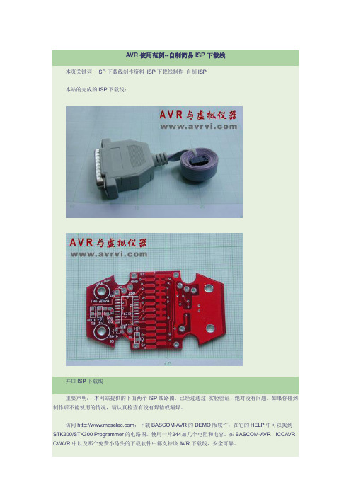
A VR使用范例--自制简易ISP下载线本页关键词:ISP下载线制作资料ISP下载线制作自制ISP本站的完成的ISP下载线:并口ISP下载线重要声明:本网站提供的下面两个ISP线路图,已经过通过实验验证,绝对没有问题。
如果你碰到制作后不能使用的情况,请认真检查有没有焊错或漏焊。
访问,下载BASCOM-AVR的DEMO版软件,在它的HELP中可以找到STK200/STK300 Programmer的电路图。
使用一片244加几个电阻和电容。
在BASCOM-AVR、ICCAVR、CVAVR中以及那个免费小马头的下载软件中都支持该AVR下载线,安全可靠。
电路图更新说明根据网友JAMESKING的描述,上面的电路图存在一些毛病。
图上的那个100欧电阻应该改为20欧或者干脆去掉,不去掉的结果就是很容易锁死芯片,而采用74LS244在3V系统使用中会出现无法下载的现象,所以也应该改为74HC244,将这两处改动后,这种下载线还是很好用的。
网上收集的最简化的设计图。
该线路图已经在SLisp1.32和PonyProg2000下测试过,下载顺利。
A VR使用范例--自制简易JTAG本页关键词:自制JTAG,JTAG使用,JTAG制作资料推荐:豪华版AVR JTAG ICE & ISP stk500二合一avr下载编程avr jtag仿真器详细使用说明书:/start/AVR_JTAG_ICE_ISP_STK500_USER_GUIDE.pdf点击图片进入论坛查看讨论。
/goods-1.html本站提供的JTAG制作资料:1按电路图接好电路,本例给出的是贴片封装,如果使用直插封装采用对应的接口即可。
2使用max232的电路图【pdf】使用分立元件的电路图(稍后奉上)将下面的HEX文件通过其他方式写入Atemega16,eeprom.hex写入eeprom,flash.hex写入flash。
官方提供的JTAG制作资料:官方提供的JTAG制作资料,点击下载。
AVR-ISP-MK2 程序器用户手册说明书

AVR-ISP-MK2A VR-ISP-MK2 programmerUSER’S MANUALRevision B, July 2012Designed by OLIMEX Ltd, 2012All boards produced by Olimex LTD are ROHS compliantOLIMEX© 2012AVR-ISP-MK2 User's Manual DISCLAIMER© 2012 Olimex Ltd. Olimex®, logo and combinations thereof, are registered trademarks of Olimex Ltd. Other product names may be trademarks of others and the rights belong to their respective owners.The information in this document is provided in connection with Olimex products. No license, express or implied or otherwise, to any intellectual property right is granted by this document or in connection with the sale of Olimex products.It is possible that the pictures in this manual differ from the latest revision of the board.The product described in this document is subject to continuous development and improvements.All particulars of the product and its use contained in this document are given by OLIMEX in good faith. However all warranties implied or expressed including but not limited to implied warranties of merchantability or fitness for purpose are excluded. This document is intended only to assist the reader in the use of the product. OLIMEX Ltd. shall not be liable for any loss or damage arising from the use of any information in this document or any error or omission in such information or any incorrect use of the product.This evaluation board/kit is intended for use for engineering development, demonstration, or evaluation purposes only and is not considered by OLIMEX to be a finished end-product fit for general consumer use. Persons handling the product must have electronics training and observe good engineering practice standards. As such, the goods being provided are not intended to be complete in terms of required design-, marketing-,and/or manufacturing-related protective considerations,including product safety and environmental measures typically found in end products that incorporate such semiconductor components or circuit boards.Olimex currently deals with a variety of customers for products, and therefore our arrangement with the user is not exclusive. Olimex assumes no liability for applications assistance, customer product design, software performance, or infringement of patents or services described herein.THERE IS NO WARRANTY FOR THE DESIGN MATERIALS AND THE COMPONENTS USED TO CREATE AVR-ISP-MK2. THEY ARE CONSIDERED SUITABLE ONLY FOR AVR-ISP-MK2.OLIMEX© 2012AVR-ISP-MK2 User's Manual The product is based on Dean Camera's LUFA USB stack. More info at:/The LUFA library is currently released under the MIT license, included below.Copyright 2012 Dean Camera (dean [at] fourwalledcubicle [dot] com)Permission to use, copy, modify, and distribute this software and its documentation for any purpose is hereby granted without fee, provided that the above copyright notice appear in all copies and that both that the copyright notice and this permission notice and warranty disclaimer appear in supporting documentation, and that the name of the author not be used in advertising or publicity pertaining to distribution of the software without specific, written prior permission.The author disclaim all warranties with regard to this software, including all implied warranties of merchantability and fitness. In no event shall the author be liable for any special, indirect or consequential damages or any damages whatsoever resulting from loss of use, data or profits, whether in an action of contract, negligence or other tortious action, arising out of or in connection with the use or performance of this software.OLIMEX© 2012AVR-ISP-MK2 User's ManualTable of Contents DISCLAIMER (2)CHAPTER 1 OVERVIEW (5)1. Introduction to the chapter (5)1.1 Features (5)1.2 Target market and purpose of the board (5)1.3 Organization (6)CHAPTER 2 SETTING UP THE A VR-ISP-MK2 BOARD (7)2. Introduction to the chapter (7)2.1 Electrostatic warning (7)2.3 Requirements (7)CHAPTER 3 A VR-ISP-MK2 BOARD DESCRIPTION (8)3. Introduction to the chapter (8)3.1 Layout (top view) (8)CHAPTER 4 RECOMMENDED SOFTWARE TOOLS (9)4. Introduction to the chapter (9)4.1 AVR-STUDIO in Windows (9)4.2 AVR-DUDE in Linux (9)CHAPTER 5 INTERFACES AND HARDWARE (10)5. Introduction to the chapter (10)5.1 Programming interfaces (10)5.1.1 10-pin ICSP (10)5.1.2 6-pin PDI (10)5.1.3 6-pin TPI (10)5.2 Upgrade firmware button (10)5.3 Jumpers description (11)5.3.1 TARGET jumper (11)5.3.2 POWER jumper (11)5.4 LEDs explained (12)CHAPTER 6 REVISION HISTORY AND SUPPORT (13)6. Introduction to the chapter (13)6.1 Document revision (13)6.2 Useful web links and purchase codes (14)6.3 Product support (15)OLIMEX© 2012AVR-ISP-MK2 User's Manual CHAPTER 1 OVERVIEW1. Introduction to the chapterThank you for choosing the AVR-ISP-MK2 programmer from Olimex! This document provides a user’s guide for the Olimex AVR-ISP-MK2 programmer. As an overview, this chapter gives the scope of this document and lists the programmer’s features. The document’s organization is then detailed.1.1 FeaturesTested and working with AVR Studio 4, AVR Studio 5, ATMEL Studio 6Connects to PC via USB 2.0 Full speedDoes not need external power supply as it takes the power supply from USBUses Atmel's 2x5 pin ICSP and 2x3 pin PDI and TPI connector layoutWorks with 5V and 3.3V targets (selectable) and can supply target with powerPrograms both flash and EEPROMSupports fuses and lock bit programmingUpgradeable for future device supportSupports target voltages from 1.8V to 5.5V2 ribbon female-female cables - 10pin and 6pinAdjustable ISP programming speed (50Hz to 8MHz SCK frequency)Dimensions: 45x30 mm (1.7x1.2") + 20 cm (8") ribbon cableAVR-ISP-MK2 can program tinyAVR and megaAVR devices using the ISP Interface, tinyAVR devices using the TPI interface, and AVR XMEGA devices using the PDI Interface.1.2 Target market and purpose of the boardAVR-ISP-MK2 is a ready to use programmer low-cost clone of AVRISP-MKII. The board is suitabe for programming chips that according to their respective datasheets allow ICSP, PDI or TPI programming modes.OLIMEX AVR-ISP-MK2 is a programmer based on the hardware of AVRISP-MKII clone open source project and the USB stack of the LUFA (Lightweight USB Framework for AVRs) project started and maintained by Dean Camera. More info about the initial idea and Dean Camera can be found here: /AVRISP.php.OLIMEX© 2012AVR-ISP-MK2 User's Manual 1.3 OrganizationEach section in this document covers a separate topic, organized as follow:–Chapter 1 is an overview of the board usage and features–Chapter 2 provides a guide for quickly setting up the board–Chapter 3 contains the general board diagram and layout–Chapter 4 mentions the main software tools used with AVR-ISP-MK2–Chapter 5 is an explanation of the interfaces, the leds, the jumpers position–Chapter 6 contains the revision history, useful links and support informationOLIMEX© 2012AVR-ISP-MK2 User's Manual CHAPTER 2 SETTING UP THE A VR-ISP-MK2 BOARD2. Introduction to the chapterThis section helps you set up the AVR-ISP-MK2 development board for the first time.Please consider first the electrostatic warning to avoid damaging the board, then discover the hardware and software required to operate the board.The procedure to power up the board is given, and a description of the default board behavior is detailed.2.1 Electrostatic warningThe AVR-ISP-MK2 comes in a plastic cover but make sure boards and devices interfacing with the programmer are properly grounded.2.3 RequirementsIn order to set up the AVR-ISP-MK2 optimally, you might need to update your set of hardware and/or software tools. The major needed components are listed below.Hardware tools:- USB-A to USB-B cable- Atmel board or chip that can be programmed by AVR-ISP-MK2. The list of supported devices can be found in the official Atmel web-site: /tools/AVRISPMKII.aspx?tab=devices- Personal computer with USB portSoftware tools:- AVR-STUDIO 4, 5 or ATMEL-STUDIO 6 with AVR-GCC compiler- AVR-DUDEOLIMEX© 2012AVR-ISP-MK2 User's Manual CHAPTER 3 A VR-ISP-MK2 BOARD DESCRIPTION3. Introduction to the chapterHere you get acquainted with the main parts of the board. Note the names used on the board differ from the names used to describe them. For the actual names check the AVR-ISP-MK2 itself.3.1 Layout (top view)OLIMEX© 2012AVR-ISP-MK2 User's Manual CHAPTER 4 RECOMMENDED SOFTWARE TOOLS4. Introduction to the chapterHere you will find short info on the most popular choices for software that can be used with the AVR programmer.4.1 A VR-STUDIO in WindowsThe most popular choice amongst AVR fans. The IDE has everything you need for software development with AVR under Windows. You can download it from the official Atmel web-site. Note that separately you will have to download the AVRGCC compiler and install it.4.2 A VR-DUDE in LinuxAnother popular choice among the AVR fans.More info on the project's web page - /avrdude/CHAPTER 5 INTERFACES AND HARDWARE5. Introduction to the chapterIn this chapter are presented the interfaces found on the programmed that can be found on the board. Jumpers functions are described.5.1 Programming interfacesAVR-ISP-MK2 has three programming interfaces aiming at different processors5.1.1 10-pin ICSPThe ICSP (in-circuit serial programming) interface is suitable for programming tinyAVR and megaAVR chips.5.1.2 6-pin PDIThe 6-pin PDI is used for programming AVR XMEGA.5.1.3 6-pin TPIThe interface used for programming tinyAVR.5.2 Upgrade firmware buttonThere is a small hole between the PDI interface and the ICSP10 interface which nests a button below. The button is used to reset the memory. The memory can then be programmed with new firmware. If you wish to update your firmware check if there is newer version in the web and follow the algorithm:1) Connect the programmer to the USB and with a sharp object (needle or pin) press the upgrade pin - it is in a small hole at the back of the board (this will start the bootloader and will turn off the LED, also probably will show a new unrecognized device in device manager for which we will install driver in step 3)2) Download and install the latest version of "Atmel Flip" software (it can be downloaded from the Atmel's web-site)3) Open its install folder and update the software of the unrecognized device (usually under "Other devices" tab) with the drivers from folder named "usb"; the device should now be recognized as AT90USB162 under "libusb-win32" tab4) Start "Atmel FLIP" and click "Select a target device" -> choose AT90USB1625) Click "Select a Communication Medium" and then USB medium6) From "File -> load HEX file" choose this HEX (CLICK FOR DOWNLOAD) and click "RUN" in the "Operations Flow" section7) Disconnect the AVR-ISP-MK2 from the USB and connect it again5.3 Jumpers descriptionPlease note that the two jumpers on the board are PTH (plated-through hole) type.5.3.1 TARGET jumperTARGET jumper controls the powering of the target board. If it is in position ON (check the diagram on the back of the plastic cover) it will provide either 3.3V or 5V to the target board (depending on the position of the POWER jumper)The default position is OFF.5.3.2 POWER jumperIf you have set the TARGET jumper to position ON POWER jumper controls whether 3.3V or 5V are provided to the target board.The default position is 5V.5.4 LEDs explainedThere are two 3mm LEDs – ORANGE and a double colored GREEN/RED.Green – when GREEN LED is on – USB connection is activeGreen – GREEN LED on and RED blink - USB connection active and programming activity (erasing, flashing, programming) – unless TARGET is onOrange – when ORANGE LED is off - TARGET jumper is in position OFFOrange – ORANGE LED on - TARGET jumper is in position on, BLINK means programming activity (erasing, flashing, programming)CHAPTER 6 REVISION HISTORY AND SUPPORT6. Introduction to the chapterIn this chapter you will find the current and the previous version of the document you are reading. Also the web-page for your device is listed. Be sure to check it after a purchase for the latest available updates and examples.6.1 Document revision6.2 Useful web links and purchase codesThe web page you can visit for more info on your device is https:///dev/avr-isp-mk2.html.You can get the latest updates on the software at: /LUFA.php . ORDER CODES:AVR-ISP-MK2 – assembled and tested AVR-ISP compatible programmerThe latest price list can be found at /dev/pricelist.html.How to order?You can order to us directly or by any of our distributors.Check / and /dev/order.html for more info.6.3 Product supportFor product support, hardware information and error reports mail to: ******************. Note that we are primarily a hardware company and our software support is limited.Please consider reading the paragraph below about the warranty of Olimex products.AVR-ISP-MK2。
Mabz 双龙 AVR ISP USB 2 使用方法

安装步骤:1 安装AvrStudio4Setup.exe (不要链接下载器到电脑。
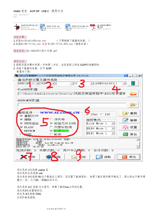
)2 安装SLISP_V1716.exe 或者SLISP_V1716_SU8.exe(推荐后者)使用参考:SL-USBISPII用户手册.pdf使用方法:1 按照安装步骤中的第一步和第二步后。
会在桌面上形成SLISP 的快捷图标。
2 连接下载器到电脑,打开SLISP 。
配置如下图:在红色的1处选择uspisp Ⅱ在红色的2 处选择usb在红色的3处选择50.这个数值自己调节,是设置下载速度的,如果下载后程序数字都乱了,那么将这个数字调整大一些,大于50.一般50应该可以。
在红色的4处选择芯片型号,和要下载的hex 文件的位置。
在红色5处设置熔丝位。
在红色6处选择JTAG 。
红色7--9 是按钮。
Mabz 双龙 AVR ISP USB 2 使用方法星期二2012年8月7日8:52特别注意:::在步骤5中需要进行如下操作:1 步骤5 必须按照上面圆圈5 的选择。
尤其不能把加密选上,可能导致avr 锁死,不能使用。
2 然后配置熔丝位,必须先配置熔丝位才能继续步骤 6 ,7,8,9编程。
在步骤5中点击配置熔丝会出来如下的对话框:在熔丝位配置中必须按照这个方式来选择。
在该打勾的地方打勾后,点击写入,会提示写入成功。
然后确定。
在继续操作步骤6--9.注 :2012 10 31 添加两个熔丝位。
BODENCKOPT选择熔丝位的时候把这两个位置打勾。
勾选是使能该位,熔丝置1.。
AVRISPMKII使用说明

AVRISPMKII使用说明AVRISP MKII是一款用于编程和调试AVR微控制器的工具。
它通过USB接口连接到计算机,并与Atmel Studio集成开发环境一起使用,提供了快速,可靠的编程和调试功能。
本文将详细介绍AVRISP MKII的使用方法。
一、连接与安装1.将AVRISPMKII连接到计算机的USB接口上。
2.如果之前没有安装过驱动程序,则计算机会自动检测到设备并提示进行驱动安装。
二、在Atmel Studio中配置AVRISP MKII1. 打开Atmel Studio集成开发环境。
2.在“工具”菜单下选择“外部工具”选项。
3.点击“添加”按钮,弹出“外部工具”窗口。
4. 在“标题”栏中输入“AVRISP MKII”,在“命令”栏中输入“avrdude.exe”的路径,一般为“Atmel\Atmel Toolchain\AVR8GCC\Native\3.6.2.1759\avr8-gnu-toolchain\bin\avrdude.exe”。
5.在“参数”栏中输入以下内容:-c avrispmkII:指定使用AVRISP MKII编程器-p设备型号:指定要编程的AVR微控制器型号-P usb:指定使用USB接口连接-e -U flash:w:"$(ProjectDir)Debug\$(TargetName).hex":r:擦除芯片并将目标文件烧录到芯片上6. 在“初始目录”栏中输入“$(ProjectDir)Debug\”:指定工程的目录。
7.点击“应用”和“确定”保存设置。
三、编程与调试1.打开需要编程和调试的工程。
2. 在Atmel Studio的工具栏上选择“工具”按钮,然后选择“AVRISP MKII”选项,开始编程和调试。
3.在“解决方案资源管理器”窗口中右键单击工程名称,选择“属性”选项。
4.在左侧的面板中选择“调试”选项。
5. 将“调试工具”设置为“AVRISP mkII”。
2、AVR单片机视频教程 ISP烧写器驱动安装方法

HJ-ISP AVR烧写器驱动安装方法
基于慧净HJ-2G开发板讲解 主讲:陈老师
驱动程序包在哪里?
• 找到第二节课 • 打开慧净USBasp-win-driver-x86-x64-win10驱动 目录
开始安装 点开installDriver
• 本驱动兼容XP WIN7 WIN8 WIN10 32位 64位系统
开始安装
安装完成
HJ-ISP下载器接入电脑USB口
在设备管理器里可以看到设备名称
出现问题处理方法
• 1、驱动没有安装成功 • 需要重新安装好驱动 • 2、找不到HJ-ISP下载器硬件 • 需要换一个USB口,换一台电脑试一下 • 3、下载器不稳定 • 廷长线不要大长,要接在电脑主机后面的USB口 • 4、供电不稳定 • 笔记本下载器,需要在开发板上接上供电线
谢谢
AVR编译器及SL_ISP(双龙电子)AVR_MCU烧录程序使用要点[1]
![AVR编译器及SL_ISP(双龙电子)AVR_MCU烧录程序使用要点[1]](https://img.taocdn.com/s3/m/55b78a49852458fb770b566f.png)
一.编译程序安装:WinA VR-20060421-install.exe双击桌面上的:Programmers Notepad [WinA VR]图标,启动程序。
1.选择:File/New/Prpject/输入你欲建立的文件夹名及欲放置的位置。
(在Name栏输入你欲建立的文件夹名(如“wenjiam”),在folder栏输入你欲放置该文件夹的位置),点击OK后就会在该位置产生一个文件夹。
并在窗口的左边显示出来。
2.右击新建立的文件夹(如“wenjiam”),选择Add New Folder。
就会产生一个子文件夹,并将其改名为普遍使用的头文件夹名:“inc”。
右击“inc”文件夹,选择Add Files导入你的头文件。
另外再产生一个放c文件的文件夹并改名为:“c”。
右击“c”文件夹,选择Add Files导入你的c文件。
双击c文件即可打开编辑。
3.双击桌面上的“MFile [WinA VR]”图标。
选择makefile/make file name…/在makefile栏里输入“main”。
然后点击“OK”,在窗口里会产生一句话:“TARGET = main”。
再选择makefile/MCU type,选择你需要的MCU型号。
选择File/Save as/使用默认文件名“Makefile”保存文件(一般叫“链接文件”)到你已建立的文件夹里。
在Programmers Notepad [WinA VR]程序里的“c”文件夹里导入刚刚建立的“Makefile”文件。
双击“Makefile”文件,修改里面的参数:在“SRC =”后面加入已导入的所有c文件名,每个文件名之间用空格隔离,并保存文件。
(其中F_CPU = 8000000是CPU的主频率4;FORMA T = ihex是编译后的目标文件格式,此句为:.hex文件;TARGET = main是目标文件名。
这几句在做“Makefile”时已选好,此处不用修改),)4.选择主菜单的Tools/Make all即可编译该文件。
AVR芯片的ISP全攻略

A VR芯片的ISP全攻略并行编程,最早的编程方法,功能最强大,但需要连接较多的引脚,通常需要12V~24V的高压,以示区别,下面称为高压并行编程。
ISP(In System Programmability) 在系统编程,简称为串行下载IAP(In Application Programing) 在应用编程,BootLoader也是类似的意思1 ISP虽然利用了SPI接口(例外:M64/M128为UASRT0接口,Tiny13等没有SPI接口)的引脚,但只在复位时起作用,而且下载完成后合格的下载器会自动断开端口的连接,对正常工作时没有影响的(在产品应用中,下载器一定是不会一直粘在上面的)。
2 虽然高压并行下载能修复任何熔丝位,但对于贴片封装来说是很不现实的,所以ISP接口是最常用的下载方式了3 虽然IAP是一种新的升级方法,但IAP程序本身也是要先用高压并行下载或ISP来烧进芯片里面才行4 Tiny13等少管脚AVR芯片因为管脚实在太少了,有ISP,但没有[高压并行编程]而特制了[高压串行编程] 所以,产品上一般都留有ISP接口插座,或更省位置的----留6个焊盘就行了ISP的工作前提1 芯片没有物理损坏2 芯片的SPIEN熔丝位=0 使能ISP功能3 芯片的RSTDISBL熔丝位=1 RESET引脚有效(假如芯片有这个熔丝位)4 线路正常---------接错线?短路?5 下载器正常-------特别要考虑连线的接触不良问题6 电源运行时钟ISP时钟(必须低于运行时钟的1/4)4096Hz <1024Hz //很变态的用法,外接32.768KHz晶体+CKDIV8 ,不过A VRISP还是提供了603Hz这个速度了//另一简易解决办法是下载时在32.768KHz晶体并联一个1MHz晶体,双龙的下载线就配有一个8MHz的石英晶体32768Hz <8192Hz128KHz < 32KHz //内部RC128KHz1.0MHz <250KHz //默认值(包括8MHz+CKDIV8),所以A VRISP的ISP速度多为230KHz 8.0MHz <2000KHz16.0MHz <4000KHz运行时钟不等于震荡器的频率,因为部分A VR芯片有系统时钟预分频器,可以对震荡器进行1~256分频CKDIV8熔丝位决定CLKPS位的初始值。
AVR芯片的ISP全攻略

AVR 芯片的ISP 全攻略
并行编程,最早的编程方法,功能最强大,但需要连接较多的引脚,通
常需要12V~24V 的高压
ISP(In System Programmability) 在系统编程,简称为串行下载
IAP(In Application Programing) 在应用编程,BootLoader 也是类似的意思
1 ISP 虽然利用了SPI 接口(M64/M128 除外),但只在复位时起作用,而且下载完成后合格的下载器会自动断开端口的连接,对正常工作时没有影响的( 在产品应用中,下载器一定是不会一直粘在上面的)。
2 虽然高压并行下载能修复任何熔丝位,但对于贴片封装来说是很不现实的,所以ISP 接口是最常用的下载方式了
3 虽然IAP 是一种新的升级方法,但IAP 程序本身也是要先用高压并行下载或ISP 来烧进芯片里面才行
所以,产品上一般都留有ISP 接口插座,或更省位置的----留6 个焊盘就行了
ISP 的工作前提。
使用并口的AVR单片机串行ISP

文章编号:1006-1576(2006)06-0091-02使用并口的AVR单片机串行ISP胡捷(西南科技大学信息与控制工程学院,四川绵阳 621010)摘要:使用PC标准并口实现AVR单片机串行ISP时,若引脚/RESET接地,则可利用SPI总线实现串行编程。
即选用PC机并行接口的/STROBE、/INIT、DATA0和/BUSY引脚分别连接到AVR的/RESET、SCK、MOSI和MISO,并设定/AUTOFDXT产生1MHz MCU工作时钟。
其编程通过汇编语言编制并采取速度优化。
关键词:串行ISP;PC标准并口;AVR中图分类号:TP302.2文献标识码:ASerial ISP of AVR Microcontroller Based on Parallel PortHU Jie(College of Information & Control Engineering, Southwest University of Science & Technology, Miangyang 621010, China) Abstract: Using PC standard parallel port to realize serial ISP of AVR, if pin /RESET was connected to the ground, the SPI bus could be used to realize the serial programming. That is, connecting the /STROBE, /INIT, DATA0 and BUSY pins of the PC parallel port to the /RESET, SCK, MOSI and MISO pins of the AVR, and making /AUTOFDXT pin to generate a work clock of 1MHz MCU. The assembler language was used as the program’s language, and the speed optimization was also adopted.Keywords: Serial ISP; PC standard parallel port; AVR microcontroller0 引言Ateml公司AVR 8-bit RISC单片机基于新的精简指令RISC结构,具有最高MIPS/mW能力[1],提供串行ISP功能。
avr_isp制作

根据网上的资料整理制作的基于M8的USB接口的ASPISP下载线。
做了30几块,有30几位使用,除个别由于焊接问题,没有发现大的问题。
现提供全部资料。
资料中,已经增加了VISTA下的USBISP驱动程序。
现在在XP和VISTA 下都可以使用。
JTAG与ISP下载区别JTAG是Joint Test Action Group(联合测试行动小组)的缩写,是一种国际标准测试协议(IEEE 1149.1兼容),主要用于芯片内部测试。
JTAG用来对芯片进行测试的基本原理是在器件内部定义一个TAP(Test Access Port;测试访问口)通过专用的JTAG测试工具对内部节点进行测试。
标准的JTAG接口是4线:TMS、TCK、TDI、TDO,分别为模式选择、时钟、数据输入和数据输出线。
TMS:测试模式选择。
此引脚用来实现TAP 控制器各个状态之间的切换。
TCK:测试时钟。
JTAG 操作是与TCK 同步的。
TDI:测试数据输入--需要移位到指令寄存器或数据寄存器(扫描链)的串行输入数据。
TDO:测试数据输出-- 自指令寄存器或数据寄存器串行移出的数据。
现在,JTAG接口还常用于实现ISP(In-System Programmable;在线编程),对EEPROM、FLASH等器件进行编程和在线调试。
JTAG编程方式是在线编程,传统开发流程中先对芯片进行预编程再装到板上的模式因此而改变,简化的流程为先固定器件到电路板上,再用JTAG编程,从而大大加快工程进度。
AVR 的JTAG功能(只有部分型号才有)使得AVR的调试工作非常简单,可以通过JTAG 接口对Flash、EEPROM、熔丝位和锁定位进行编程。
使用AVR studio软件和JTAG硬件(AVR JTAG编程器,AVR JTAG仿真器)可以进行程序下载(亦即编程)和程序在线调试。
通过JTAG功能,工程师可以方便的观察各个寄存器的变化和程序的运行情况,十分适合单片机的学习与系统开发。
AVR单片机的并口ISP下载线原理及制作

AVR 单片机的并口ISP 下载线原理及制作
为了给AVR 单片机业余爱好者,尤其大学生DIY 一条ISP 下载线,可以一线打天下,开发所有AVR 系列各种封装的AVR 单片机,特提供二种成熟电路供DIY。
应注意电路接线及电源不能接错,造成器件损坏后果自负。
说明:双龙电子提供的SL-DIY 系列功能板,有的配有ISP 并口下载电缆线。
图1 最简单的ISP 并口下载线电原理图
图2 标准并口ISP 下载插座接线功能图
图3 具有信号隔离的并口下载线电原理图
下载软件可选用小马软件PonyProg2000(因快捷图标是一只小马,打开后会发出马叫声,所以也称小马软件)软件。
可从英特网上下载安装。
也可选用双龙电子的SLISP 免费下载软件,并可对AT89S 系列单片机进行ISP 下载,不过要注册后才能使用。
AVR ISP程序下载说明

AVR程序下载
一、 AVR Studio的安装
双击aStudio4.13.exe文件进入安装界面,安装完成后重启电脑即可。
二、 AVR ISP下载器操作方法
1、打开AVR STUDIO。
在Tools->Program AVR->Connect中Platform选择STK500 or AVRISP,Port可以使用Auto让STUDIO自己找,也可直接选择AVRISP 对应的COM口,点击Connect进入下一步。
2、下载器连接正常会进入下面编程(Program)界面。
主要包括有器件(Device)、编程模式(Programming mode)、Flash下载、EEPROM下载几个部分,最下面部分是信息窗口。
Device选择ATmega16;
Programming mode选择ISP mode,选中Erase Device Before和Verify Device After Program;
Flash,Input HEX File处导入需下载的程序;
点击Program进入烧录步骤。
烧录时,界面底部有提示进程。
三、AVR ISP下载器连接错误
1、AVR ISP下载时重复出现下面窗口:
问题原因:PC机与AVR ISP下载线连接不成功。
问题出在PC与AVR下载线之间,查看串口连接是否正确、AVR下载线是否上电。
2、AVR ISP下载时窗口弹出如下窗口:
问题原因:AVR ISP下载线与目标芯片连接不成功。
问题出在AVR ISP下载线与目标芯片之间,查看ISP接口是否正确。
AVR_ISP下载线使用说明

AVR ISP 下载线使用说明
本文只介绍AVR ISP 下载线在AVR Studio 环境下的下载方法,推荐使用。
此处所说的STK500下载线和AVR ISP 下载线同属一类,它们使用相同的通信协议,STK500确切的说是一个学习板,AVR ISP 才是真正意义上的下载线。
AVR ISP 下载线实物图片
AVR ISP 连接示意图
ISP 接口
支持芯片列表
AVR ISP 下载线支持芯片型号非常多,这里就不一一列出了,只要AVR 芯片支持ISP 下载的都可以。
AVR ISP 下载线-操作方法:1、双击,安装软件。
2、连接好开发板的电源和下载线,使用USB转串口的下载线请先安装驱动。
3、打开AVRStudio
软件,按下图操作。
AVR-ISP
STK500
4、在弹出菜单中单击“Cancel”
5、连接
(1)点击图示位置图标:
(2)选择串口
在这里选择所用器件及连接端口,使用默认选项STK500or AVRISP下载线自动检测端口,点击"Connect"进入下一步。
(3)弹出下面界面表示连接成功,否则连接失败。
4、程序烧录:步骤1:选择芯片
步骤2:设置熔丝位,详见《AVR熔丝位的设置》
步骤3:烧录HEX文件。
如下图所示:
烧录ATMEGA16L时只需在FLASH区点击①调入相关的HEX文件,点击②开始烧录。
步骤4:烧录完成。
怎样制作AVR单片机ISP下载线

怎样制作AVR单片机ISP下载线
下面介绍利用Protel99se电路绘图软件和热转印技术制作这种下载线的方法和步骤。
一、设计ISP下载线
PCB文件利用Protel99se绘带0《自带AVR单片机ISP下载线》一文中的原理图1(为方便制作,可省略该图中的VDl)。
并将图中各元件按附表所述进行封装选择。
原理图绘制完毕后,依次点击原理图编辑器中的Tools(工具)/Up-date PCB(更新原理图)菜单,自动生成下载线PCB文件。
在编辑下载线PCB 文件时,可先按图1所示规划PCB板的大小和布局PCB板上的元件,然后让系统自动布线(为减小PCB尺寸,采用双面布线),最后对自动布线作适当调整,经过手动调整布线后的PCB板如图2所示。
二、分图层打印。
AVR单片机并口ISP下载线的工作原理及其程序设计

C lang uage. KEYWORDS A V R M CU , par allel po r t ISP dow nlo ad cable, pr inciple , ser ial do wnloading , pr og ramm ing
ISP 下载线是从事 A VR 单片机学习和开发的必 备工具, 很多人都在使用ISP 下载线。但是, 相信多数 人都没有做过 ISP 下载的程序设计。其中很重要的一 个原因是因为相关的硬件电路和软件设计都 比较复 杂, 不能在短期内完成。为此, 本文介绍一种硬件电路 和软件设计都很简单的 ISP 下载的程序设计。
图 1 并口 ISP 下载线工作原理图
1. 1 PC 机并口电路 PC 机 并 口 电 路[ 2] 由 74L S373 数 据 锁 存 器 和
74L S240 状态缓冲器组成。数据锁存器 74L S373 的 I/ O 地址为 378H, 该端口称为数据 端口。状态缓冲 器 74L S240 的 I/ O 地址为 379H, 该端口称为状态端口。 数据端口为可读可写端口, 状态端口为只读端口, 图中 只画出了与串行下载有关的部分。其中, 数据端口只画
第 21 卷 第 10 期
电脑开 发与应用
( 总 805) ·47·
文章编号: 1003-5850( 2008) 10-0047-04
AVR 单片机并口 ISP 下载线的工作原理及其程序设计
The Principle and Programming of Parallel Port ISP
Download Cable of AVR MCU
por t cir cuit and the cir cuit of ISP do w nload cable, and int ro duces AV R M CU 's ser ial pro gr amming instruction as well as it's
AVR USB ISP 下载器 说明书

AVR USB ISP下载器产品用户手册文件版本: Version 1.2适用产品版3.0第 1 页版权声明:本手册版权属A VR 与虚拟仪器公司所有,未经本公司书面许可,任何人不得对此说明书和其中所包含的任何资料进行复制或翻译成其他语言。
因IT 市场变化迅速,编辑时间有限,不保证本手册中没有错误,所以本手册仅供用户参考使用,不提供任何形式的担保。
本公司保留对本文内容的修订及产品软硬件的修改的权力。
对于所作修改,公司没有责任和义务通知任何个人及单位。
商标:本手册中使用到其他公司的注册商标,特声明如下:Microsoft 和Windows 是微软公司的注册商标。
AVR 、A VR Studio 是ATMEL 公司的注册商标。
其他在本手册中使用的产品名称是它们各自所属公司所拥有。
技术支持:A VRVi 网站:A VRVi 论坛:A VRVi 商城:技术支持信箱:support@技术支持热线:0531-********传真:0531-********本产品全国联保,也可直接接洽当地分公司。
第 2 页简介:USB A VRISP 是专业的低价位的在线编程器,支持所有的A VR 8位精简指令的单片机。
A VRISP 可直接通过USB接口与 PC 机连接。
并且可以直接利用目标板上的电源而不需要额外供电。
特点:¾A VR Studio 接口¾所有A VR芯片都可以使用ISP编程¾可以对Flash和EEPROM进行编程¾支持熔丝位和锁定位的编程¾支持RC振荡器校准¾可以升级以支持最新的芯片¾可以工作在2.7伏到5.5伏电压之间¾速度可调,支持所有高于8KHZ的目标板¾使用USB接口连接到PC来实现编程和控制¾可直接利用目标板供电而不需要额外供电¾A VR Studio完全支持A VRISP,我们推荐使用最新的A VR Studio 4.12支持芯片:Classic:AT90S1200、AT90S2313、AT90S/LS2323、AT90S/LS2343、AT90S/LS2333、AT90S4414、AT90S/LS4433、AT90S/LS4434、AT90S8515、AT90S/LS8535Tiny 系列:第 3 页ATtiny12、ATtiny13、ATtiny15、ATtiny22、ATtiny24、ATtiny26、ATtiny2313Mega 系列:ATmega8、ATmega16、ATmega32、ATmega48、ATmega64、ATmega88、ATmega103、ATmega128、ATmega161、ATmega162、ATmega163、ATmega165、ATmega169、ATmega323、ATmega325、ATmega329、ATmega644、ATmega645、ATmega649、ATmega2560、ATmega2561、ATmega3250、ATmega3290、ATmega6450、ATmega6490、ATmega8515、ATmega8535、AT90CAN128、AT90PWM2、AT90PWM3①同样支持该列所有芯片的低电压版本其他:T86RF401、AT89S51、AT89S52装箱清单:① A VR USB ISP下载器 1台②产品说明书 1本③优质USB连接线 1条④ 10PIN备用连线1条⑤ 6PIN转接线1条⑥手工升级用电缆 1条⑦技术资料及驱动光盘 1张系统要求:最低的软硬件需求是:486处理器(推荐奔腾系列)16 MB 内存15 MB 空闲硬盘空间Windows®95,Windows98,Windows NT4.0,Windows 2000 或第 4 页Windows XPUSB接口使用方法:驱动安装:使用USB A VRISP 需要安装USB驱动,驱动程序可以在光盘中获得,也可以在以下地址下载:/down.php?file=product/USB Driver.exe直接双击文件,一直下一步即可完成安装,如下图:第 5 页驱动安装完成后,如果插上A VRUSP,系统会自动识别设备,这时候通过计算机的设备管理器(右键我的电脑>>管理>>设备管理器),可以看到Prolific USB-Serial Controller(COM*)的字样,COM 口根据机器不同,稍有差异,一般会默认识别为COM3。
AVRISP MKII使用说明

AVRISP MKII编程器使用说明谢谢您使用A VRISPMKII下载器如有问题,可与我处技术支持部门联系A VR单片机开发工具网友情赞助,提供测试所需的各种开发平台,再这里向A VR单片机学习网的朋友致以诚挚的谢意。
网址:/总体介绍产品简介A VRISP MKII 下载器是ATMEL 公司开发的A VRISP 第二代产品,USB接口。
A VRISP MKII 支持全系列A VR + 部分其他芯片(如S51等)。
USB接口,便于使用与携带,特别适用于没有串口的台式电脑和笔记本电脑。
A VRISP MKII是一种结构紧密而且容易使用的在线编程工具,它为ATMEL 系列A VR 单片机开发应用程序设计。
由于其尺寸小,它也成为一种为现有的利用A VR单片机的应用程序局升级的极好的工具。
A VRISP MKII是由USB供电,因而A VR ISP 编程器无需额外能源供应。
A VRISP MKII编程接口是集成于A VR Studio中的。
Flash,EEPROM和所有的Fuse和Lock bit可编程ISP选项,可以选择单个分别编程或者连续自动编程。
我公司生产的A VRISP MKII在线编程器和atmel官方的A VRISP MKII在线编程器功能上完全兼容,但价格更低,是工厂,学校,个人等开发A VR单片机的首选工具。
产品特点A VR Studio4.1x 接口支持所有A VR芯片的ISP编程可以对Flash和EEPROM进行编程支持熔丝位和锁定位的编程支持RC振荡器校准可以工作在2.7伏到5.5伏电压之间速度可调,支持50Hz~4MHz的isp时钟频率使用USB高达4MHz的全速通讯,兼容USB2.0可直接利用USB供电而不需要额外供电A VR Studio完全支持A VRISPMKII,我们推荐使用最新的A VR Studio 4.X。
支持芯片型号AT90PWM1、AT90PWM2、AT90PWM216、AT90PWM2B、AT90PWM3、AT90PWM316、AT90PWM3B。
- 1、下载文档前请自行甄别文档内容的完整性,平台不提供额外的编辑、内容补充、找答案等附加服务。
- 2、"仅部分预览"的文档,不可在线预览部分如存在完整性等问题,可反馈申请退款(可完整预览的文档不适用该条件!)。
- 3、如文档侵犯您的权益,请联系客服反馈,我们会尽快为您处理(人工客服工作时间:9:00-18:30)。
AVR系列ISP方法
图1
1、AT90SXXXX系列ISP原理图如上图1所示。
图2
图3
2、ATmegaXX系列ISP原理图如上图2图3所示。
图4
3、ATtinyXX系列ISP原理图如上图3所示。
4、AVR内部还有数据EEPROM可以在线编程。
5、目标电路板最简系统需求:晶振(4MHz以上),目标MCU,5V电源(供目标板及下载型编程器用)。
6、设计电路板时目标单片机的ISP相关管脚最好专门供ISP使用,而不要设计其他功能。
7、单片机RESET管脚的使用说明。
如果复位电路由RC电路组成则RESET管脚可以直接相连接,同时提醒您为了MCU的安全电容不能过大,建议取值1uF到4.7uF,最好不要超过10uF;电阻建议取值10K,最好不要小于4.7K。
注释:图中的标示如“ISPro.MOSI”表示ISPro编程器下载头的MOSI引脚。
