BMC BIRT-Excel-Emitter
亿佰特(Ebyte)-E30是贴片型无线串口模块(UART)-透明传输方式-具有空中唤醒功能
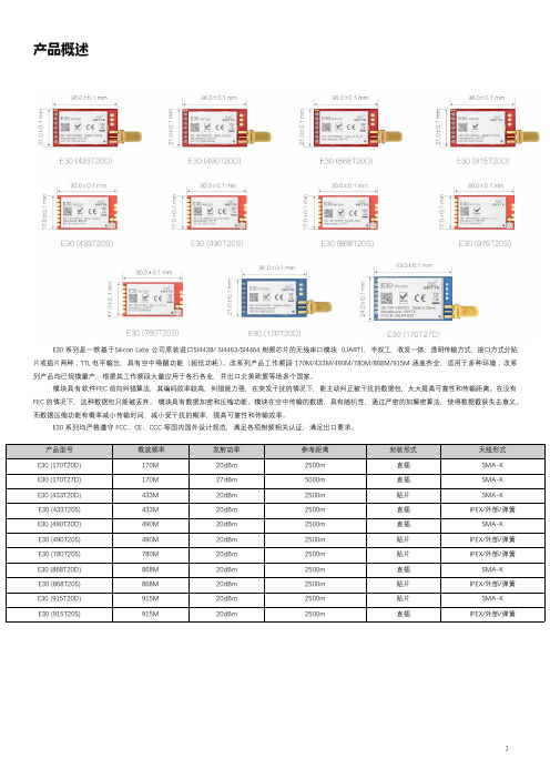
产品概述E30系列是一款基于Silicon Labs公司原装进口SI4438/SI4463/SI4464射频芯片的无线串口模块(UART),半双工,收发一体,透明传输方式,接口方式分贴片或插片两种;TTL电平输出,具有空中唤醒功能(超低功耗)。
改系列产品工作频段170M/433M/490M/780M/868M/915M涵盖齐全,适用于多种环境;改系列产品均已规模量产,根据其工作频段大量应用于各行各业,并出口北美欧盟等地多个国家。
模块具有软件FEC前向纠错算法,其编码效率较高,纠错能力强,在突发干扰的情况下,能主动纠正被干扰的数据包,大大提高可靠性和传输距离。
在没有FEC的情况下,这种数据包只能被丢弃。
模块具有数据加密和压缩功能。
模块在空中传输的数据,具有随机性,通过严密的加解密算法,使得数据截获失去意义。
而数据压缩功能有概率减小传输时间,减小受干扰的概率,提高可靠性和传输效率。
E30系列均严格遵守FCC、CE、CCC等国内国外设计规范,满足各项射频相关认证,满足出口要求。
目录1.产品特点 (4)2.技术参数 (4)7.1通用参数47.2电气参数52.2.1.发射电流52.2.2.接收电流52.2.3.关断电流62.2.4.供电电压62.2.5.通信电平67.3射频参数72.3.1.发射功率72.3.2.接收灵敏度72.3.3.推荐工作频率72.4实测距离 (8)3.机械特性 (8)4.推荐连线图 (11)5.功能详解 (12)7.7定点发射 (12)5.2广播发射125.3广播地址125.4监听地址135.5模块复位135.6AUX详解135.6.1串口数据输出指示 (13)5.6.2无线发射指示135.6.3模块正在配置过程中 (13)5.6.4AUX注意事项146.工作模式 (14)6.1.模式切换146.2一般模式(模式0) (15)6.3唤醒模式(模式1) (15)6.4.省电模式(模式2) (15)6.5.休眠模式(模式3) (15)7.指令格式 (15)7.1出厂默认参数 (16)7.1.1工作频率170M (16)7.1.2工作频率433M (16)7.1.3工作频率490M (16)7.1.4工作频率780M (16)7.1.5工作频率868M (16)7.1.6工作频率915M (17)7.2工作参数读取 (17)7.3版本号读取177.4复位指令177.5参数设置指令 (17)8.参数配置 (19)9.生产指导 (20)9.1回流焊温度209.2回流焊曲线图 (20)10.常见问题 (21)9.1通信距离很近 (21)9.2模块易损坏2111.重要声明 (21)12.关于我们 (21)1.产品特点●【超低功耗】:即空中唤醒功能,特别适用于电池供电的应用方式:当模块处于省电模式下即模式2时,配置模块的接收响应延时时间可调节模块的整机功耗,模块可配置的最大接收响应延时为2000ms,在此配置下模块的平均电流约30uA。
远程终端单元通信单元560CMR01说明书

Communication Unit 560CMR01RTU560 product line Remote Terminal Units - Data sheetRTU560 product lineCommunication module for RTU560 with 32 bitCPU•2x serial communication interface (RS-232 or RS-485) for remote communication •2x Ethernet interface (10/100BaseT)•1x USB port•1x serial peripheral bus•Battery buffered real time clockApplicationThe 560CMR01 communication unit is one of the CMU modules of the RTU560 product line.The essential tasks are:•Managing and controlling of the I/O modules via theinterface to the serial I/O bus.•Reading Process events from the input modules.•Send commands to the output modules.•Communicating with control systems and local HMIsystems via the serial interfaces (RS232) and the Ethernet 10/100BaseT interfaces.•Communication with Sub-RTU’s, IED’s or multimeterdevices via the interfaces (RS485) and the Ethernet interfaces.•Managing the time base for the RTU560 product linestation and synchronizing the I/O modules.•Handling the dialog between RTU560 product line andWeb-Browser via the LAN interfaces.Within the RTU560 racks the board occupies . Thecommunication unit is able to handle Ethernet- and UART-character based communication protocols.The unit has a battery buffered real time clock (RTC).The unit is available in 2 versions:•R0001: with standard cyber security functions•R0002: with security chip for advanced cyber securityfunctionsFigure 1: Block diagram 560CMR01CharacteristicsOn the applied ARM cortex A8 controller AM3352 a real-time operating system is implemented. The 560CMR01is responsible for the interface management, the event handling, the time base and the internal data base. The controller acts as master for the SPB I/O bus (serial peripheral bus). RTU560 synchronizes itself to the timereferences supplied by 560RTC0x. The time information of the 560RTC0x is provided to the 560CMR01 on the backplane of the sub-rack.System relevant configuration files are stored in the non-volatile flash memory card (removable SD-card™) in order to guarantee a valid system configuration after Power on Reset (PoR).A battery buffered RTC is used to keep an exact time during power off state.The communication unit provides the following interfaces:•Communication Port 1 and 2 (CP1 & CP2): serial interfaces according RS232C or RS485 with RJ45connectors. The communication ports can beconfigured independant as SPB I/O bus interface tothe front.•Ethernet interface 1 and 2 (E1 & E2): 10/100BaseT with RJ45 connector.•USB 2.0 device interface for diagnosis andmaintenance purposes.•The SPB I/O bus is directly connected to the backplane connector.Technical dataIn addition to the RTU500 series general technical data, the following applies:Main Processing Unit MPUCPU ARM cortex A8, AM3352 @800 MHzRAM128 MByteBoot Flash8 MByteSD cardConnector SD card slot (push push) Type SD 2.0, class 2Capacity 4 GByteReal time clock RTC (Backup)Battery Lithium 3 V DC, CR2032 Time resolution 1 sec, 1ms with timesync Battery lifetime> 10 yearsFree running± 50 ppmSerial interfaces CP1 and CP2Connector RJ45Type RS232C or RS485RS232C:Bit rate200 bit/s - 38.4 kbit/sSignal lines GNDTxDRxDRTSCTSDTRDCD E2/102 D1/103 D2/104 S2/105 M2/106 S1.2/108 M5/109Level typical: ± 6VRS485:Bit rate200 bit/s - 38.4 kbit/s Level typical: ± 6VEthernet interface E1 and E2Connector RJ45Type IEEE 802.3, 10/100BaseTUSB interfaceConnector micro USB Type AB(female)Type USB 2.0 device, low, fulland high speed (max. 480MBit/s)Cable type to PC USB Type A <-> micro USBType B Current consumption for power supplied via RTU560 backplane5 V DC500 mA24 V DC 3 mASignaling by LEDsERR (red)ON: RTU in error stateFlashing: RTU in warningstateFor more details seeRTU500 series FunctionDescriptionRUN (green)Communication module inoperationT Transmit data on serialcommunication ports CPR Receive data on serialcommunication ports CPS Ethernet communicationspeed:ON: 100 Mbit/sOFF: 10 Mbit/sL Link up (ON) / Activity(Flashing) on Ethernetinterface EMechanical layoutDimensions160 mm x 100 mm, 3HEeuro card format4R (20 mm) front panel Housing type Printed circuit board Mounting for mounting in RTU560racksWeight0.14 kgConnection typeRTU560 backplaneconnector48 pole type F DIN 41612Immunity testElectrostatic dischargeIEC 61000-4-28 kV air / 6 kV contact (level3)Performance criteria A Radiated Radio-FrequencyElectromagnetic FieldIEC 61000-4-310 V/m (level 3)Performance criteria A Electrical Fast Transient /BurstIEC 61000-4-44 kV (level X)Performance criteria A SurgeIEC 61000-4-52 kV (level 3)Performance criteria A Conducted Disturbances,induced by Radio-Frequency FieldsIEC 61000-4-610 V (level 3)Performance criteria AImmunity testDamped oscillatory wave IEC 61000-4-182.5 / 1 kV (level 3) Performance criteria AEnvironmental conditions - climatic Operating temperatureEN 60068-2-14-25 °C ... 70 °CStart upEN 60068-2-1-40 °CMax. operating temperature,max. 96hEN 60068-2-2+85 °CRelative humidity EN 60068-2-305 ... 95 % (non condensing)Ordering information560CMR01 R00011KGT036200R0001 560CMR01 R00021KGT036200R0002ABB Power Grids Germany AG P.O. Box 10 03 5168128 Mannheim, Germany /rtu We reserve the right to make technicalchanges or modify the contents of thisdocument without prior notice. With regardto purchase orders, the agreed particularsshall prevail. Hitachi ABB Power Grids doesnot accept any responsibility whatsoeverfor potential errors or possible lack ofinformation in this document.We reserve all rights in this document and in thesubject matter and illustrations contained therein.Any reproduction, disclosure to third parties orutilization of its contents – in whole or in parts – isforbidden without prior written consent of HitachiABB Power Grids.© 2020 Hitachi Power GridsAll rights reservedABB is a registered trademark of ABBAsea Brown Boveri Ltd. Manufactured by/for a Hitachi Power Grids company.1KGT15915V71。
锐捷网络RGRIILBMC关键业务运行管理中心产品介绍
RG-RIIL-BMC关键业务运行管理中心产品介绍星网锐捷网络有限公司目录1 产品图片 (1)2 产品概述 (2)3 产品特性 (6)4 技术参数 (14)5 典型应用 ............................................................................................................................ 错误!未定义书签。
6 订购信息 (15)1 产品图片产品运行界面图2 产品概述锐捷网络基于RIIL平台的“关键业务系统运行监控中心”实施对网络和业务应用系统的集中智能管理,可以让有限的IT运维人员精力和IT预算投入到最关键的资源的维护和保障中,降低复杂IT环境的管理难度,更轻松地把握支撑关键业务的网络和系统的运行状态,并不断提升关键业务系统的运行服务质量水平,提升用户满意度。
随着信息化建设的推进,为了让凝聚了巨大人力物力投入的信息基础设施发挥出其效益,保障整个信息系统的平稳可靠运行,需要有一个可从整体上对包括IP网络,存储,安全等组件在内的IT基础设施环境进行综合管理的平台,并能够提供业务系统运行异常的实时告警和进行图形化问题定位,性能趋势分析和预警,能够基于关键业务系统的角度,以业务重要性为导向进行事件处理和通知。
由于信息系统是一个包括了众多软件,硬件技术,设计多厂家产品,从网络,安全,存储,计算到中间件和应用的复杂异构环境,而且随着信息建设的深入和持续优化和发展,这个复杂庞大的基础设施,还会随之不断进行演进,在产品,技术和网络结构,业务关系上不断发生变化,因此,要求针对该环境进行管理的系统具有良好的可扩展性,能够将下层网络和的复杂度有效的通过抽象屏蔽起来,向上层应用和运维流程开放稳定的接口。
基于这样的需求背景,我们从融合,开放的技术理念出发,提出了基于实时智能基础设施库的“关键业务系统运行监控中心(RIIL-BMC)”的建设思路。
IT6500 用户手册
版权所有 © 艾德克斯电子有限公司
iv
IT6Байду номын сангаас00 用户手册
目录
认证与质量保证................................................................................................................................................... 1 保固服务 .............................................................................................................................................................. 1 保证限制 .............................................................................................................................................................. 1 安全标志 .............................................................................................................................................................. 1 安全注意事项 ...................................................................................................................................................... 2 环境条件 .............................................................................................................................................................. 2 法规标记 .............................................................................................................................................................. 3 废弃电子电器设备指令(WEEE).................................................................................................................... 3 符合性信息 .......................................................................................................................................................... 3
亿佰特的2.4GHz低功耗数采通讯模块 E107-SC01使用手册

目录第一章概述 (1)1.1 简介 (1)1.2 特点功能 (2)1.3 应用场景 (2)第二章规格参数 (2)2.1 极限参数 (2)2.2 工作参数 (3)第三章机械尺寸与引脚定义 (4)第四章工作模式 (6)第五章功能介绍 (6)5.1网络模型 (6)5.2网络ID (6)5.3中心 (6)5.4节点 (7)第六章参数配置 (7)第七章硬件设计 (8)第八章常见问题 (9)8.1 传输距离不理想 (9)8.2 模块易损坏 (9)8.3 误码率太高 (9)第九章焊接作业指导 (10)9.1 回流焊温度 (10)9.2 回流焊曲线图 (10)第十章天线指南 (11)10.1 天线推荐 (11)10.2 天线选择 (11)第十一章批量包装方式 (12)修订历史 (12)关于我们 (12)第一章概述1.1 简介E107-SC01系列是2.4GHz低功耗数采通讯模块;其极低的节点静态功耗,支持大规模星型网络组网,网络节点数量理论上无限制,可应用于室内或小区域范围内,数采和传感器采集系统。
此模块为小体积贴片型(引脚间距1.27mm),模块自带高性能PCB板载天线与IPEX接口。
该模块具有超低静态功耗,平均电流小于1uA,无线采用跳频数据传输,具有较好的抗干扰能力;高达1Mbps空中速率数据传输效率高;数据发送协议握手机制,杜绝数据丢包。
支持逻辑网络划分功能,最大支持65535个逻辑分组,实现同区域范围内多分组同时工作。
适用于工业数采,智能家居、智能穿戴等设备,室内定位等。
1.2 特点功能●逻辑网络分组支持多达65536个。
●数采发送端静态低功耗小于1uA。
●支持空中数据加密。
●支持无线跳频收发功能。
●支持LBT有效避免射频冲突●支持数据重传确保不丢包。
●支持数据rssi检测,可用于简单室内定位●实测通讯距离可达110米;●最大发射功率+5dBm,支持软件多级可调;●支持免许可ISM 2.4GHz频段;●支持GFSK调制模式;●工业级标准设计,支持-40~+85℃下长时间使用;●双天线可选(IPX/PCB),利于集成;●支持1Mbps空中速率传输;1.3 应用场景●智能家居以及工业传感器等;●安防系统、定位系统;●无线遥控,无人机;●无线游戏遥控器;●医疗保健产品;●无线语音,无线耳机;●汽车行业应用。
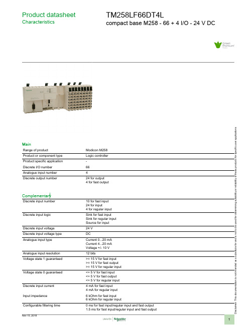
模组说明书:Modicon M258 TM258LF66DT4L
i s c la i me r : T h i s d o c u m e n t a t i o n i s n o t i n t e n d e d a s a s u b s t i t u t ef o r a n d i s n o t t o b e u s e d f o r d e t e r m i n i ng s u i t a b i l i t y o r r e l i a b i l i t y o f th e s e p r o d u c t s f o r s p e ci f i c u s e r a p p l i c a t i o n sProduct datasheetCharacteristicsTM258LF66DT4Lcompact base M258 - 66 + 4 I/O - 24 V DCMainRange of productModicon M258Product or component type Logic controller Product specific application -Discrete I/O number 66Analogue input number 4Discrete output number24 for output 4 for fast outputComplementaryDiscrete input number10 for fast input 24 for input4 for regular input Discrete input logicSink for fast input Sink for regular input Source for input Discrete input voltage 24 V Discrete input voltage type DCAnalogue input typeCurrent 0...20 mA Current 4...20 mA Voltage +/- 10 V Analogue input resolution 12 bitsVoltage state 1 guaranteed>= 15 V for fast input >= 15 V for fast output >= 15 V for regular input Voltage state 0 guaranteed<= 5 V for fast input <= 5 V for fast output <= 5 V for regular input Discrete input current 4 mA for fast input 4 mA for regular input Input impedance 6 kOhm for fast input 6 kOhm for regular inputConfigurable filtering time0 ms for fast input/regular input and fast output 1.5 ms for fast input/regular input and fast output12 ms for fast input/regular input and fast output4 ms for fast input/regular input and fast outputAnti bounce filtering 2 µs...4 ms (configurable) fast input/regular input and fast outputCable distance between devices30 m for fast input30 m for fast output30 m for regular input500 Vrms ACIsolation between channels andinternal logicIsolation between channels NoneDiscrete output logic SourceDiscrete output voltage24 V DCOutput voltage limits19.2...28.8 VDiscrete output current 4 mA for fast output[Us] rated supply voltage24 V DC for embedded expert modules power24 V DC for I/O power segment24 V DC for main supplySupply voltage limits20.4...28.8 V[In] rated current0.04 A for embedded expert modules power0.31 A for main supply10 A for I/O power segmentPeak current<= 100 kA during <= 70 s main supply<= 25 kA during <= 500 s I/O power segment<= 50 kA during <= 150 s embedded expert modules power<= 1.2 kA during > 70 s main supplyPower consumption in W<= 18.11 WExecution time per instruction22 ns : BooleanMemory description Flash 128 MBInternal RAM 64 MBRealtime clock With user calibration realtime clock, drift: <= 6 s/monthWithout any user calibration realtime clock, drift: < 30 s/month at 25 °CData backed up Variables of type retain and retain persistent CR2477M Renata, 1.5 years autonomy Integrated connection type 1 CANopen male SUB-D 9, CANopen master1 isolated serial link female RJ45, Ethernet Modbus TCP/IP slave (10BASE-T/100BASE-TX)2 free slots PCI1 isolated serial link female RJ45, Modbus master/slave RTU/ASCII or character mode ASCII(RS232/RS485), 300...115200 bps1 isolated serial link mini B USB, 480 Mbit/s1 isolated serial link USB type A, 480 Mbit/sTransmission rate125 kbit/s for bus length of 500 m, CANopen250 kbit/s for bus length of 250 m, CANopen50 kbit/s for bus length of 1000 m, CANopen500 kbit/s for bus length of 100 m, CANopen10 kbit/s for bus length of 5000 m, CANopen1000 kbit/s for bus length of 4 m, CANopen20 kbit/s for bus length of 2500 m, CANopen800 kbit/s for bus length of 25 m, CANopenCounting input number8 counting input(s) 200 kHzLocal signalling 1 LED per channel for I/O state1 LED for CAN0 STS1 LED for MBS COM1 LED green/red for APP01 LED green/red for APP11 LED green/red for Eth NS (Ethernet network status)1 LED green/red for Eth ST (Ethernet status)1 LED green/red for RUN/MS (module status)1 LED green/red for USB host1 LED green/yellow for Eth LA (Ethernet activity)1 LED red for BATT (battery status)Marking CEMounting support Symmetrical DIN railWidth262.5 mmHeight99 mmDepth85 mmProduct weight0.8 kgEnvironmentStandardsCSA C22.2 No 142IEC 61131-2UL 508CSA C22.2 No 213Product certificationsCSA C-Tick cULus GOST-RAmbient air temperature for operation0...55 °C without derating factor horizontal installation 0...60 °C with derating factor horizontal installation 0...50 °C vertical installation Ambient air temperature for storage -25...70 °CRelative humidity 5...95 % without condensation IP degree of protection IP20 conforming to IEC 61131-2Pollution degree 2 conforming to IEC 60664Operating altitude 0...2000 m Storage altitude 0...3000 mVibration resistance 1 gn 8.4...150 Hz DIN rail 3.5 mm 5...8.4 Hz DIN rail Shock resistance15 gn for 11 msResistance to electrostatic discharge 4 kV on contact conforming to EN/IEC 61000-4-28 kV in air conforming to EN/IEC 61000-4-2Resistance to electromagnetic fields 1 V/m 2...2.7 GHz conforming to EN/IEC 61000-4-310 V/m 80...2000 MHz conforming to EN/IEC 61000-4-3Resistance to fast transients1 kV I/O conforming to EN/IEC 61000-4-41 kV shielded cable conforming to EN/IEC 61000-4-42 kV power lines conforming to EN/IEC 61000-4-4Surge withstand0.5 kV differential mode conforming to EN/IEC 61000-4-51 kV common mode conforming to EN/IEC 61000-4-5Disturbance radiated/conductedCISPR 11Offer SustainabilitySustainable offer status Green Premium productRoHS (date code: YYWW)Compliant - since 1039 - Schneider Electric declaration of conformity Schneider Electric declaration of conformity REAChReference not containing SVHC above the threshold Reference not containing SVHC above the threshold Product environmental profile AvailableProduct environmental Product end of life instructionsAvailableEnd of life manualContractual warrantyWarranty period18 monthsDimensions DrawingsControllerDimensionsTM5 System Wiring RecommendationsWire Sizes to Use with Removable Spring Terminal BlocksExternal Power SuppliesWiring Diagram of the Controller Power Distribution Module(1)Internal electronics(2)24 Vdc I/O power segment integrated into the bus bases (3)PS1/PS2: External isolated SELV power supply 24 Vdc (4)External fuse, Type T slow-blow, 3 A 250 V (5)External fuse, Type T slow-blow, 2 A 250 V(6)External fuse, Type T slow-blow, 10 A max., 250 V。
亿佰特(Ebyte)-E01nRF24L01芯片-内置PA+LNA-带屏蔽-抗干扰-低辐射-板材特殊-耐高温的无线模块

E01 系列是成都公司标志性产品的 2.4G 无线模块,SPI 接口,目前已经稳定量产,并适用于多种应用场景。 E01 系列采用挪威 Nordic 公司原装进口的 nRF24L01P 芯片,所有阻容感器件均采用进口元器件,尤其是晶体,我们使用了高精度宽温晶体,保证其工业特 性。发射功率为 20dBm 的模块内置了 PA 功率放大器与 LNA 低噪声放大器,从而提高通信稳定性,延长通信距离;发射功率为 0dBm 的模块均采用进口器件, 优秀的设计亦保证了卓越的射频性能,是追求低功耗的客户首选。 E01 系列均严格遵守 FCC、CE、CCC 等国内国外设计规范,满足各项射频相关认证,满足出口要求。
1.1. 通用参数 3 1.2. 电气参数 3 1.2.1. 发射电流 3 1.2.2. 接收电流 3 1.2.3. 关断电流 3 1.2.4. 供电电压 4 1.2.5. 通信电平 4 1.3. 射频参数 4 1.3.1. 发射功率 4 1.3.2. 接收灵敏度 4 1.3.3. 推荐工作频率............................................................................................................................................................................................. 5 1.4. 实测参数 5 1.4.1. 实测距离 5 2. 机械特性.............................................................................................................................
Bird 4421 RF Power Meter 44说明书

Bird 4421 RF Power Meter44SpecificationsNOTE: Due to the wide variety of available connectors, frequencyrange and maximum power may be reduced. Insertion loss isspecified with female N connectors. Choose connectors appropriate for the frequency and power of operation.Bird 4421 RF Power MeterFrequency Range Sensor dependent Power Range Sensor dependent VSWR Display 1.0 – 199.9 max Return Loss Display 0 to 40 dB maxDisplay Accuracy ± 1 on least significant digit AC Power 115/230 Vac @ 50/60 HzBatteries 8 C-size Nickel Cadmium rechargeable 1.2 volt cells, 15 W max (NEDA Type 10014)Battery Life Minimum 8 hours continuous usage Battery ChargerBuilt-in battery charger. Drained batteries require approximately 28 hours to recharge.DisplayLCD, 3 ½ digit display. Indicates mode,measurement units, battery condition, remote status, and signal increase/decrease. Self contained backlight.Optional Interfaces IEEE-488 GPIB RS-232Fuse RatingIEC (5 x 20 mm) Type T 115 Vac 230 Vac 0.25 A 0.125 AEmissions/Immunity EMC Directive 89/336/EEC Safety Low Voltage Directove 73/23/EEC Humidity 95% ± 5% max. (noncondensing)AltitudeUp to 10,000 feet (3,048 m)Temperature RangeOperating Storage 0 to 50 °C (32 to 122 °F)–20 to +50 °C (–4 to +122 °F)Dimensions 15.5”L x 12.25”W x 4.25”H (393 x 311 x 108 mm)Weight9.5 lbs. (4.3 kg) nominal1981Maintenance45Specifications Common to all SensorsImpedance 50 ohms nominalVSWR Range 1.00 to 2.00 (40.0 to 9.5 dB Return Loss)Sampling Rate Approximately 2 readings/secondCalibration Technique Calibration vs. frequency curve stored in nonvolatile memory in each sensor. Sensor output corrected at frequency of measurement within rated range.Operating Power Supplied by power meter via sensor cable ConnectorsCustomer specified (See “Available Connectors” on page 50)Emissions/Immunity EMC Directive 89/336/EEC Safety Low Voltage Directove 73/23/EEC Humidity 95% ± 5% max. (noncondensing)AltitudeUp to 10,000 feet (3,048 m)Temperature RangeOperating Storage 0 to 50 °C (32 to 122 °F)–20 to +50 °C (–4 to +122 °F)Dimensions 5.4”L x 2.5”W x 3.25”H (137 x 64 x 83 mm)Weight, Nominal1 lb. 13 oz. (0.8 kg)Bird 4421 RF Power Meter46Bird 4020 Series RF Power SensorsPower Range4021, 40224024, 4025300 mW – 1 kW3 W – 10 kWFrequency Range40214022402440251.8 – 32 MHz25 MHz – 1 GHz1.5 – 32 MHz100 kHz – 2.5 MHzAccuracy, Fwd± 3%Insertion VSWR (Insertion Loss)4021, 4024, 402540221.05 (0.05 dB) max1.05 (0.05 dB) max, 25 – 512 MHz1.10 (0.13 dB) max, 512 MHz – 1 GHz Directivity, Minimum4021, 40224024402530 dB30dB (2.5 – 25 MHz), 28 dB (1.5 – 32 MHz)30 dB (125 – 2500 kHz), 28 dB (100 – 125 kHz) Signal PurityFor rated accuracy no more than 1% AMHarmonics –50 dB or lessMaintenance47CAUTIONChanging the sensor’s connectors will invalidate calibration data,and may reduce the maximum power rating of the unit.Bird 4027A Series RF Power SensorsPower Range4027A12M 4027A25M 4027A35M 4027A60M 4027A100M 4027A150M All other models300 mW – 1 kW 3 W – 9 kW 3 W – 7.5 kW 3 W – 6 kW 3 W – 5 kW 3 W – 4 kW 3 W – 10 kWFrequency Range (Calibration Frequency)4027A250K 4027A400K 4027A800K 4027A2M 4027A4M 4027A10M 4027A12M 4027A25M 4027A35M 4027A60M 4027A100M 4027A150M 250 – 400 kHz (250 kHz)400 – 550 kHz (400 kHz)800 – 950 kHz (900 kHz)1.5 – 2.5 MHz (2.0 MHz)3 – 5 MHz (4.0 MHz)10 – 15 MHz (13.56 MHz)10 – 15 MHz (13.56 MHz)25 – 30 MHz (27.12 MHz)35 – 45 MHz (40.0 MHz)45 – 65 MHz (60.0 MHz)95 – 105 MHz 150 – 170 MHzAccuracy±2 % from maximum range to 30 % of full scale on the most sensitive range±1 % at calibration frequency and power level Repeatability ±1 % maximum unit to unit at calibration frequency and power level Insertion VSWR (Insertion Loss) 1.05 (0.05 dB) maxDirectivity, Minimum4027A12MAll other models 30 dB 28 dBSignal PurityFor rated accuracy no more than 1% AM Harmonics –50 dB or less Calibration Power Level1 kW unitsAll other models700 W 1700 WBird 4421 RF Power Meter48Bird 4027F Series RF Power SensorsPower Range100 W – 10 kWFrequency Range4027F2M4027F10M1.8 –2.2 MHz12 – 15 MHzPower Accuracy15 to 35 °C (59 to 95 °F)0 to 50 °C (32 to 122 °F)± 1%± 3%Harmonic Rejection, Minimum4027F2M4027F10Mfrequency > 3.8 MHz:30 dB3.6 – 3.8 MHz:26 dBfrequency > 25 MHz:30 dB Low Frequency Rejection, Minimum (4027F10M Only) frequency < 1 MHz30 dBAM Rejection< 5 kW, 10% AM5 – 10 kW, 10% AM< 0.2% error< 1% errorInsertion VSWR(Insertion Loss)1.05 (0.05 dB) max Directivity, Minimum28 dBCalibration Power Level1700 W nominal Calibration Frequencies4027F2M4027F10M1.80,2.00, 2.20 MHz12.0, 13.56, 15.0 MHzMaintenance49IEEE-488 Interface ModuleLogic Levels Meets all IEEE Standard 488-1978 specificationsModes of OperationSwitch and bus selectableTalk Only Allows the 4421 to send to the bus keyboard-initiated measurements onlyAddressableAllows the 4422 to be addressed as talker or listener under the command of an IEEE-488 bus controllerConnector Standard IEEE-488 bus typeHumidity 95% ± 5% maximum (non-condensing)AltitudeUp to 10,000 feet (3,048 m)Temperature RangeOperating Storage 32 to 122º F (0 to 50º C)–4 to +122º F (–20 to +50º C)Dimensions 6.5”L x 4.5” W (165.1 x 114.3 mm)Weight0.5 lbs (0.227 kg) nominalRS-232 Interface ModuleLogic Levels Meets all EIA Standard RS-232-C specifications Modes of OperationSwitch and bus selectableTalk Always Allows the 4421 to send to the bus keyboard-initiated measurements onlyAddressable Allows the 4421 to be commanded by an RS-232 interface controller Connector RS-232 Interface TypeHumidity 95% ± 5% maximum (non-condensing)AltitudeUp to 10,000 feet (3,048 m)Temperature RangeOperating Storage 32 to 122º F (0 to 50º C)–4 to +122º F (–20 to +50º C)Dimensions 6.5”L x 4.5” W (165.1 x 114.3 mm)Weight0.5 lbs (0.227 kg) nominal。
挑战者M451系列芯片说明书

Applications ◆ Industrial Automation ◆ LED Control Board ◆ Home Automation◆Motor Control ◆ Power MeterContactus:*******************M451NuMicro® M451 SeriesCortex ®®-M4F, CAN and USB OTGNuvoton NuMicro® FamilySelection Guide*Marked in the block diagram (4+1) means 4 UART + ISO-7816 UARTFeatures◆ Core– ARM® Cortex®-M4F core running up to 72 MHz– DSP extension with hardware divider– IEEE 754 compliant Floating-point Unit (FPU)– Memory Protection Unit (MPU)– Single-cycle 32-bit hardware multiplier◆Built-in LDO for wide operating voltage ranged from 2.5V to5.5V◆Flash Memory– 256/128/72/40 KB Flash memory– Configurable program code/data allocation– 4 KB Flash for loader (LDROM)◆SRAM Memory– 32/16 KB embedded SRAM– 16/8 KB with hardware parity check◆Clock Control– Built-in 22.1184 MHz internal high speed RC oscillator (HIRC) for systemoperation (variation < 2% at -40˚C ~ +105˚C)– Built-in 10 kHz internal low speed RC oscillator (LIRC) for Watchdog Timer and wake-up operation– Built-in 4~20 MHz external high speed crystal oscillator (HXT) for precisetiming operation– Built-in 32.768 kHz external low speed crystal oscillator (LXT) for RTC function and low-power system operation◆GPIO– Four I/O modes– TTL/Schmitt trigger input selectable– Supports 5V-tolerance function– Supports up to 85 GPIOs◆Timer– Supports 4 sets of 32-bit timers with 24-bit up-timer and one 8-bit prescale counter– Independent clock source for each timer– Provides One-shot, Periodic, Toggle and Continuous Counting operationmodes– Event counting function to count the event from external pin– Input capture function to capture or reset counter value◆RTC– External power pin V BAT– Wake-up function– 80 bytes spare registers– Tamper detection function◆PWM– Supports up to 12 independent PWM outputs with 16-bit resolution– Maximum clock frequency up to 144 MHz– Trigger EADC/DAC start conversion– Capture counter with 16-bit resolution– Capture interrupt– Capture PDMA mode◆UART– Supports up to four UARTs – UART0, UART1, UART2 and UART3– 16-byte FIFOs with programmable level trigger– RS-485 9-bit mode and direction control– UART0 and UART1 support LIN function– Wake-up function– PDMA mode◆Smart Card Interface– Supports one set of ISO-7816-3 port– Supports UART function ◆SPI– Supports one set of SPI Quad controller – SPI0– Supports Master or Slave mode operation– Master up to 32 MHz, and Slave up to 16 MHz (when chip works at V DD = 5V)◆SPI / I2S– Supports up to two sets of SPI controllers – SPI1 and SPI2– Supports Master or Slave mode operation– Master up to 32 MHz, and Slave up to 16 MHz (when chip works at V DD = 5V)– Supports up to two sets of I2S by SPI controllers SPI1 and SPI2◆I2C– Supports up to two sets of I2C devices– Master/Slave mode– Supports SMBus and PMBus– Supports speed up to 1Mbps– Multi-address Power-down wake-up function◆CAN 2.0– Supports up to 1 set of CAN controller– Supports CAN protocol version 2.0 part A and B– Bit rates up to 1M bit/s– Supports power-down wake-up functionUSB 2.0 FS Controller– Supports one set of USB 2.0 FS OTG– FS Host compatible with Open HCI 1.0 specification– Compliant to USB specification version 2.0– OTG compliant with USB OTG Supplement 1.3– On-chip USB Transceiver– Provides remote wake-up capability– On-chip 5V to 3.3V LDO for USB PHYEADC– Supports single 12-bit SAR ADC conversion– Analog input voltage range: 0~ V REF (Max to AV DD)– Up to 1MSPS conversion rate at 5.0V– Up to 16 external single-ended analog input channels– Supports PDMA transferDAC– Supports a 12-bit voltage type DAC– Rail to rail settle time 8us– External reference voltage V REF– Max. output voltage AV DD -0.2V at buffer mode– Conversion started by software enable or PDMA triggerAnalog Comparator– Supports up to two rail-to-rail analog comparators– Supports a multiplexed I/O pin at positive node– Supports triggers for break events and cycle-by-cycle control for PWMCyclic Redundancy Calculation Unit– Supports four common polynomials CRC-CCITT, CRC-8, CRC-16, and CRC-32 Voltage Adjustable Interface– Supports user Configurable 1.8~5.5V I/O Interface with a dedicated power input (V DDIO)– Supports UART1, SPI0, SPI1, I2C1 or I2C0 interfaceSupports 128-bit Unique Customer ID (UCID)Operating Temperature: -40˚C~105˚CPackages– All Green package (RoHS)– LQFP 100-pin (14mm x 14mm)– LQFP 64-pin (10mm x 10mm)– LQFP 64-pin (7mm x 7mm)– LQFP 48-pin (7mm x 7mm)。
MC9RS08KA4_8中文数据手册
3FFE
3FFF
BC(JMP 机器码)
跳转地址高字节
跳转地址低字节
飞 3.4 激活背景调试模式 背景调试功能是由 RS08 核内的 BDC 管理的。在软件开发过程中,BDC 提供了
H 一种分析 MCU 操作方法。 C 有 4 种激活背景调试的方法:
*在 POR 期间或发出背景调试强制复位命令之后,拉 BKGD/MS 引脚为低
3
北京飞锐泰克科技有限公司 tel:010-59831537 fax:010-59831536
诺控通讯teri优质设备联网服务器用户手册M0802 V1.4
目录第一章系统简介 (3)1.1概述 (3)1.2功能特点 (3)1.3规范与标准 (4)第二章硬件安装 (6)2.1 设备结构 (6)2.2 设备安装 (7)2.2.1 连接电源 (7)2.2.2 连接网络 (7)2.2.3 连接串口设备 (8)2.2.4 指示灯说明 (9)2.2.5 设备启动及Reset复位开关的使用 (10)第三章设备配置和管理 (10)3.1 设备管理方式 (10)3.1.1 Web浏览器管理方式 (10)3.1.2 Telnet管理方式 (12)3.1.3 Console控制台管理方式 (14)3.2 设备参数设置 (16)3.2.1 设备参数结构 (16)3.2.2 设备配置 (16)第四章软件安装 (42)4.1 软件安装 (42)4.1.1 系统要求 (42)4.1.2 软件安装 (42)4.2 软件设置 (42)4.2.1 软件运行、设置 (42)4.2.2 固件程序升级 (43)第五章故障排除 (45)5.1 常见故障排除 (45)附件: (45)A. 接口线序 (45)B. Modbus功能码、地址、数据类型: (47)第一章系统简介1.1概述M0802串口、I/O设备联网服务器(简称:M0802)是我司自主研发的RS-232/485/422串口、Digital Input/Output接口设备联网产品。
M0802系列产品采用32位处理器,结合高效的嵌入式系统,使设备运行更加安全、稳定。
M0802系列串口、I/O联网服务器产品让用户无需投入大量资金来进行更换或升级,就可以使原有的RS-232/485/422串口、开关量工业控制设备立即具备网络互联能力,为串口数据信息提供高效、安全、稳定的数据通道。
M0802系列产品被广泛应用于通信、控制领域,如电力监控、机房监控、PLC、智能电表、煤气表、生物识别装置、读卡机等环境,是连接串口设备及TCP/IP以太网络的桥梁。
Digi 设备商品说明书

!"
#
1.1 Overview .......................................................................................................................................... 4 1.2 Features of the UART Application Kit............................................................................................ 4 1.3 Conventions...................................................................................................................................... 4 1.4 Acronyms and abbreviations ........................................................................................................... 5
Variables to be replaced with actual values are shown in italics.
4ቤተ መጻሕፍቲ ባይዱ
UART Application Kit for Windows Embedded CE 6.0 - User's Manual
Style Menu name > option
语言分配系统Integrus zh-CHS用户手册说明书
目录 | zh-CHS 5
71 72 73 73 73 73 74 74 76 77 77 77 78 79 79 79 79 80 80 82 84 86
Bosch Security Systems B.V.
用户手册
2020.06 | V1.6 |
6 zh-CHS | 安全
语言分配系统
1
!
安全
在安装或操作产品之前,请始终阅读 部分中的安装说明 安装, 页面 32 以及随电源供电产品提供的安 全说明。
语言分配系统
3.2
Integrus 发射机
发射机是 Integrus 系统的核心组件。 它接受来自多达 32 个外部通道的不对称音频源(视发射机类型 而定),并且可与新一代 DCN 网络会议系统配合使用。 此外,它可以与模拟讨论和同声传译系统(例 如,具有多达 12 个译员台的 CCS 900)配合使用,或者用作独立系统,分配外部音频源。 发射机前视图
服务请求 维护 技术数据 电气数据 整个系统的特性 发射机和模块 辐射板和附件 接收机、电池组和充电装置 缆线和连接器 机械数据 发射机和模块 辐射板和附件 接收机、电池组和充电装置 环境条件 整个系统条件 规则和标准 整个系统的合规性 保证矩形覆盖区域 2.00 以上硬件版本的辐射板的公制单位数值 2.00 以上硬件版本的辐射板的英制单位数值 2.00 以下硬件版本的辐射板的公制单位数值。 2.00 以下硬件版本的辐射板的英制单位数值。
CCS 900),或者连接到 LBB 3222/04 6 通道译员台。
红外辐射板 目前提供有两种辐射板: – LBB 4511/00 中功率辐射板,用于中小型会场 – LBB 4512/00 大功率辐射板,用于大中型会场 辐射板可安装在墙壁上、天花板上或落地支架上。
固纬电子实业MFG-2000系列多通道函数信号发生器使用手册说明书

多通道函数信号发生器MFG-2000系列使用手册固纬料号NO.82MF32K000EC1ISO-9001认证企业2015.07本手册所含资料受到版权保护,未经固纬电子实业股份有限公司预先授权,不得将手册内任何章节影印、复制或翻译成其它语言。
本手册所含资料在印制之前已经过校正,但因固纬电子实业股份有限公司不断改善产品,所以保留未来修改产品规格、特性以及保养维修程序的权利,不必事前通知。
固纬电子实业股份有限公司台湾台北县土城市中兴路7-1号目录安全说明 (6)产品介绍 (10)面板介绍 (12)显示 (21)设置信号发生器 (22)快速操作 (24)如何使用数字输入 (26)如何使用帮助菜单 (27)顯示區域的分配 (29)选择波形 (30)调制 (32)扫描 (41)脉冲串 (43)ARB (45)工具栏 (51)菜单树 (52)默认设置 (70)操作 (72)CH1/CH2通道 (74)RF通道 (87)Pulse 通道 (98)功率放大器 (109)调制 (112)3幅值调制 (AM) (115)幅移键控 (ASK) 调制 (122)频率调制 (FM) (128)频移键控 (FSK) 调制 (134)相位(PM)调制 (140)相移键控 (PSK) 调制 (146)脉冲宽度(PWM)调制 (151)总和(SUM)调制 (157)频率扫描 (163)脉冲串模式 (172)辅助系统功能设置 (182)存储和调取 (183)选择远程接 (187)系统和设置 (191)通道功能设置 (195)双通道操作 (199)任意波形 (204)插入内置波形 (205)显示任意波形 (207)编辑任意波形 (214)输出任意波形 (223)存储/调取任意波形 (225)远程接口 (234)确立远程连接 (239)网络浏览器控制界面 (244)指令列表 (252)4状态寄存器指令 (260)接口设置指令 (263)应用指令 (264)输出指令 (270)脉冲设置指令 (279)幅值调制(AM)指令 (283)振幅键控(ASK)指令 (288)频率调制(FM)指令 (292)频移键控(FSK)指令 (297)相位调制(PM)指令 (301)相位键控(PSK)指令 (305)总和调制(SUM)指令 (309)脉宽调制(PWM)指令 (314)频率扫描(Sweep)指令 (319)脉冲串模式(Burst)指令 (329)任意波形(ARB)指令 (340)计频器(Counter)指令 (348)相位 (Phase) 指令 (350)耦合(Couple)指令 (351)存储和调取指令 (354)错误信息 (356)SCPI状态寄存器 (369)附录 MFG-2000系列规格 (375)EC符合性声明书 (385)GLOBL HEADAQARTERS (386)任意波内建波形 (387)索引 (395)56安全说明本章节包含操作和存储信号发生器时必须遵照的重要安全说明。
信息系统灾备体系总体技术方案

信息系统容灾咨询服务项目灾备体系总体技术方案目录1综述 (6)1.1项目背景 (6)1.2文档导读 (6)1.3设计原则 (7)1.4术语定义 (8)2信息系统现状及当前风险 (11)2.1信息系统现状 (11)2.1.1信息系统业务架构 (11)2.1.2信息系统关联关系 (12)2.1.3信息系统物理部署架构 (14)2.1.4信息系统物理部署位置与架构 (14)2.1.5系统数据库架构现状 (16)2.1.6信息系统数据库概况 (17)2.1.7数据中心网络架构 (19)2.2生产系统主要威胁 (19)2.3生产系统脆弱点 (20)2.4业务停顿财务损失估算 (21)3恢复能力评估及差距分析 (23)3.1数据保护及系统灾备现状 (23)3.2当前恢复能力评估 (24)3.3当前灾备能力 (27)3.4灾备需求回顾 (27)3.5差距分析及结论 (28)4灾备架构设计方案 (29)4.1灾备系统总体架构 (29)4.2业务系统灾备架构设计 (31)4.2.1生产管理系统(Hipack-F) (31)4.2.2安全气囊系统(SRS) (32)4.2.3整车品质检测系统(VQC) (32)4.2.4生产打印系统(SIP) (33)4.2.5制造执行系统(GMES) (34)4.2.6电子采购系统(EPS) (35)4.2.7数据传输系统(DCS) (38)4.2.8零部件销售系统(HiPack-P) (39)4.2.9整车销售管理系统(OSM) (40)4.2.10特约店管理系统(DMS) (42)4.2.11客户关系管理系统(CRM) (44)4.2.12讴歌特约店管理系统(ACURA DMS) (46)4.2.13用友财务系统(FMS) (47)4.2.14合同管理系统、费用报销系统(CMS、RBS) (48)4.2.15邮件系统(EMS) (49)4.2.16RSA(RSA) (51)4.2.17统一认证平台(SSO) (52)4.2.18域管理控制系统(AD) (53)4.2.19数据传输平台(ETL) (53)4.2.20企业服务总线(ESB) (54)4.2.21其他系统 (56)4.3生产系统灾备适应性改造方案 (58)4.3.1业务系统单边化(DCS,EPS,CMS/RBS) (58)4.3.2业务系统DNS域名访问改造 (58)4.3.3业务系统数据迁移整体思路(从旧存储到新存储的部分) (59)5灾备网络架构方案 (60)5.1网络背景概述 (60)5.1.1数据中心区 (62)5.1.2园区网区(分为办公及生产) (62)5.1.3广域网区(特约店及分支机构区) (63)5.1.4互联网区(含DMZ区) (64)5.2容灾网络建设需求分析 (64)5.2.1xx公司数据中心网络灾备需求: (64)5.2.2xx公司广域网网络灾备需求: (65)5.2.3xx公司互联网区网络灾备需求: (65)5.2.4xx公司园区网区网络灾备需求: (65)5.3容灾网络技术方案 (66)5.3.1整体网络拓扑 (66)5.3.2灾备网络规划 (67)5.3.3数据中心网络灾备设计(含关键技术比较) (71)5.3.4互联网区网络灾备规划及切换方案 (78)5.3.5广域网/专线区灾备规划及切换 (80)5.3.6园区网区灾备规划及切换(办公区及生产区) (82)5.3.7业务系统的灾备规划及切换 (85)6灾备存储架构方案 (89)6.1存储及SAN网络现状概述 (89)6.1.1SAN网络 (89)6.1.2A地中心存储 (89)6.1.3B地中心存储 (90)6.2存储容灾建设需求分析 (90)6.3存储SAN网络容灾技术方案 (91)6.3.1SAN网络架构设计 (91)6.3.2存储架构设计 (92)7灾备中心资源部署及切换方案 (94)7.1主机部署及切换方案 (94)7.1.1服务器背景概述 (94)7.1.2主机容灾建设需求分析 (95)7.1.3主机部署及切换方案 (100)7.2虚拟化部署及切换方案方案 (104)7.2.1VMware虚拟化现状概述 (104)7.2.2风险分析与应对 (105)7.2.3容灾与切换策略 (106)7.2.4容灾整体拓扑图 (108)7.3网络部署方案 (109)7.3.1A地核心机房扩建 (109)7.3.2业务系统IP地址改造 (110)7.3.3DNS改造(内/外) (110)7.3.4第二网络中心建设 (111)7.3.5核心交换机升级及二层打通 (111)7.3.6B地增加DMZ及广域网区 (113)7.3.7分支机构网络改造 (113)7.3.8园区网改造 (114)7.4数据库部署切换方案 (114)7.4.1数据库部署切换思路 (114)7.4.2数据部署切换步骤 (115)8灾备切换设计方案 (116)8.1灾备切换流程设计原则 (116)8.2业务系统恢复原则 (117)8.3灾难场景设计 (117)8.4业务系统切换策略 (118)8.5灾备切换技术流程示意图 (119)8.6业务系统灾难切换流程总图概览 (120)8.7AS400类业务系统(生产系统为主)切换流程 (122)8.8DB2类业务系统(销售系统为主)切换流程 (124)8.9虚拟化类业务系统(A CURA-DMS等特殊类型)切换流程 (127)8.10业务系统灾备设计汇总 (129)9灾备一期实施计划 (132)9.1整体实施计划 (132)9.2主机实施计划 (132)9.3存储实施计划 (133)9.4网络实施计划 (134)9.5虚拟化实施计划 (136)9.6应用系统实施计划 (137)10附录 (139)10.1灾备建设软硬件及服务资源清单 (139)10.1.1存储设备及服务资源清单 (139)10.1.2网络设备及服务资源清单 (142)10.2灾备软硬件产品与服务技术规格说明书 (143)10.2.1网络设备及服务资源技术规格说明书 (143)1综述1.1项目背景为提升信息系统风险控制能力,应对可能发生的信息系统灾难,保障业务健康可持续发展和战略目标的顺利实现,xx公司于2017年8月启动灾备体系建设专项工作。
上海贝尔阿尔卡特1642设备介绍 n

1642EM 设备硬件介绍 二 1642EM板卡介绍
ISA-ES1 8FE (3)槽位的板卡功能 .8路10M/100M的以太网接口 .以太网的二层交换 .以太网的数据存储在ISA-ES1板上的一张FLASH 卡
1642EM 设备硬件介绍 二 1642EM板卡介绍
FB板 风扇单元 (7)槽位 DC48_24B 电源单元 (6)槽位的板卡功能
(2)一般告警
(3)严重告警
(4)Q3接口
(5)维护终端接口
(6) Housekeeping 接口 (10) 公务话机接口
(7)DEBUG 接口(内部使用)
(8)2M外部时钟输出
(9)2M外部时钟输入 (15) 光口1 输入
(11)光口1 输出
(12) 光口1 输入 (13)板卡复位键
(14)光口1 输出
1642EM 设备操作终端与设备的连接
F口
RS232串口
笔记本
1642EM 设备操作界面简介
一、1642EM设备正常情况下是由网管管理,CT维护终端无操作权限,不能进行电路删配电路和机盘,只能查 看 1.启动1320CT 点击屏幕下方的开始菜单– 选择1320CT快捷键(参见下图)启动应用程序。
1642EM 设备硬件介绍 二 1642EM板卡介绍
FB板 风扇单元 (7)槽位 功能 FB板: . 风扇单元 .一路外部电源供电 DC48_24B电源单元 : .一路外部电源(48V /24V)供电 DC48_24B 电源单元 (6)槽位的板卡
1642EM 设备接口介绍
一、MB4-1板接口 MB4-1板卡介绍中(11)(12);(14)(15)提供两路光信号(622M) 收发处理 二、DE1B32板接口 DE1B32板卡介绍中(2)提供32路2M信号收发处理、接口阻抗75欧姆 三、ISA-ES1 8FE接口 ISA-ES1 8FE板卡介绍中1—8 提供8个10M/100M全双工以太接口
SBM2541蓝牙4.0 BLE模块数据手册说明书
数据手册SBM2541蓝牙4.0 BLE 模块——————————————产品概述SBM2541模块是公司精心设计的一款蓝牙4.0 BLE 模块,采用TI (德州仪器)高性能无线芯片CC2541作为主控制器,是一款超低功耗、高度集成、小体积的收发系统模块。
用户使用简单方便,遵循低功耗蓝牙协议,适合单模式低功耗蓝牙的应用。
————————产品应用2.4G 低功耗蓝牙系统 移动手机外设人机接口设备(鼠标、键盘) 运动和健康设备 消费者健康和医疗 家庭/楼宇自动化 消费类电子产品——————————————产品特性—————————————————◆ 蓝牙4.0 BLE 单模带透传程序,简单易用 ◆ 符合FCC 和CE 标准,符合BQB 标准要求◆ 采用高可靠性的小体积主芯片,芯片内含高性能和低功率8051内核 ◆ RF 支持250kbps ,500kbps ,1Mbps ,2Mbps 的数据速率 ◆ 出色的高达0dBm 的可编程输出功率 ◆ 接收器灵敏度(1Mbps 时为-94dBm ) ◆ 工作模式RX 低至:17.9mA ◆ 工作模式TX (0 dBm):18.2mA◆ 超低待机功耗(睡眠模式3功耗:0.5uA ) ◆ 宽泛的电源电压范围(2V - 3.6V) ◆ 内置PCB 天线,也可选外接天线 ◆超小尺寸: 16*12mm目录1. 硬件介绍 (1)1.1引脚定义 (1)1.2典型应用电路图 (2)2. 电气参数 (3)2.1建议操作条件 (3)2.2电气规格 (3)2.3直流特性 (3)3. 结构尺寸 (4)4. 订购信息 (5)5. 文档信息 (6)5.1修订历史 (6)5.2免责声明 (6)1. 硬件介绍蓝牙模块SBM2541是基于用表贴技术,体积仅为15.75m 即可实现数据透传,蓝牙通讯采点为小功率短距离通讯,因此 1.1 引脚定义脚位序号 名称 Pin1 ANT Pin2 GND Pin3 VCC Pin4 DC Pin5 DD Pin6 TIMER4 Pin7 TIMER3 Pin8 SCL Pin9 SDA Pin10ADC7是基于芯片TICC2541设计的,内置PCB 天线,可15.75mm*11.88mm 。
力科电接口通信脉冲模板测试软件选项

力科电接口通信脉冲模板测试软件选项操作人员手册2004年2月力科公司LeCroyCorporation700 Chestnut Ridge RoadChestnut Ridge, NY10977–6499电话:(845)5786020, 传真: (845)578 5985网站:© 2004年力科公司版权所有,侵权必究。
LeCroy,ActiveDSO, ProBus,SMARTTrigger, JitterTrack, WavePro,WaveMaster和Waverunner是力科公司的注册商标。
本文中的信息代替所有早期版本的信息。
本文中的数据如有变更,恕不另行通告。
目录ET-PMT选项引言ET-PMT是一种测量电接口通信信号脉冲模板一致性的软件包。
脉冲模板测试包括:在示波器中采集一定的信号,然后比较电压随时间变化波形与标准模板。
模板定义了满足标准的信号必须保持的V,t空间区域。
下面是脉冲模板实例。
此外,每项测试通常有对准指标。
例如,一个电平可以由一个正向脉冲或负向脉冲组成(如在DS1标准中)。
然后测试可以选择测量哪个脉冲,ET-PMT软件将只自动查找这些脉冲。
ANSIT1 ITU-TDS1 E1(双绞线)DS3 E1(同轴电缆)STS-1 E2STS-3E E3---E4---STM-1E除上述标准外,还可以定义改动的或定制脉冲模板测试。
兼容能力这里介绍的ET-PMT功能兼容下面的力科示波器:●WavePro 7100, 7200和7300●WaveMaster 8620, 8600A,8500A和8300A●WaveRunner 6035(E4,STS-3E, STM-1E除外), 6050,6100, 6200●SDA6020,6000A, 5000A和3000A(所有SDA型号上标配)注: 所有SDA串行数据分析仪型号上都标配ET-PMT。
串行数据模板软件(SDM)也包括ET-PMT功能。
汉普LTE测试指导

汉普LTE类产品测试方法指导版本:V1.0共53 页(包括封面)目录1.1 CMW500初始配置设置 (3)1.2最大发射功率测试 (9)1.3最大功率衰减(MPR) (11)1.3附加最大功率衰减(A-MPR) (13)1.3配置UE功率测试 (15)1.4矢量幅度误差EVM(PUSCH) (18)1.5频率误差 (20)1.6占用带宽 (20)1.7 ACLR临道泄露比 (21)1.8绝对功率控制容限 (25)1.9相对功率控制容限 (29)1.10带内发射(InBandEmissions) (34)1.11 IQ Const (35)1.10 EVM vs C(subcarrier) (38)1.11 Spectrum Flatness (39)1.12 Spectrum Emission Mask (41)2.1 LTE Ext.BLER (42)2.2最大输入电平 (45)附录: (47)A.LTE对应频段 (47)B.EVM的计算 (50)C.频谱发射模板的通过判定 (50)D.最大功率衰减的测试目的 (50)E.LTE综测软件使用介绍 (51)F.LTE校准校准环境的搭建 (53)1.1 CMW500初始配置设置针对CMW500的初始化操作进行介绍,主要进行信令下的测试。
初始化设置(1)点击CMW500左上角RESET键,弹出复位界面(2)选择Global菜单下的Reset选项,然后点击Reset按钮确认(3)设置线损,在LTE Signaling界面下点击Config按钮,在RF Settings下选择测试端口以及线损,设置为1.00dB(4)设置功率控制模式,在LTE Signaling界面下点击Config按钮,在Uplink PowerControl下选择TX Power Control(TPC),Active TPC Setup选择为Max power模式。
(6)网络连接设置,在LTE Signaling界面下点击Config按钮,在Connection下选择Additional Spectrum Emission设置为NS_01模式。
