氢脆与坚固件Hydrogen Embrittlement
氢脆对钢的影响概述1

氢脆对钢的影响概述摘要本人介绍了氢脆的相关背景和氢脆的几种形式,分别为:氢化学反应脆裂,内氢脆裂和氢环境脆裂。
然后,根据国内外的一些研究,论述了氢脆对低合金钢、不锈钢以及高强度钢种的影响。
最后,根据氢脆的机制概括了一些氢脆的预防方法。
关键词氢脆,不锈钢,低合金钢,高强度钢.INFLUENCE OF HYDROGEN EMBRITTLEMNET ON STEELABSTRACT This article describes the background of hydrogen embrittlement and several forms of hydrogen embrittlement. The form of hydrogen embrittlement are as follows: chemical reaction of hydrogen embrittlement, the hydrogen embrittlement and hydrogen environment embrittlement crack. Then, the author of several studies at home and abroad, discusses the hydrogen embrittlement of low alloy steel, stainless steel and the impact of high-strength steel. Finally, according to the mechanism of hydrogen embrittlement outlines some methods of prevention of hydrogen embrittlement.KEY WORDS hydrogen embrittlement; stainless steel; low alloy steel; high strength steel前言氢脆是由于电化学作用产生的原子氢渗入金属材料而产生脆性破坏的一种现象。
Hydrogen+Embrittlement 氢脆
H+ preload = tensile stress 8
H2
Hydrogen embrittlement: delayed fracture
Page 8
Hydrogen De-Embrittlement
zinc
H+
H
2
fastener
H+
Baking/De-gassing
Page 9
9
Hydrogen De-Embrittlement
Page 3
3
Hydrogen Embrittlement
zinc
H+
H H+
2
H+
fastene r
H2
zinc anodes galvanic bath H+ H2 H2
H+
H+ H+
H H+ H+
2
H+
H+ H
2
H2
H
2
H+
H+
Absorption, diffusion of hydrogen
Control T° 200°C
Curves Time/T°C
200°C
6 hours
Curves Page 18
Time/T°C
18
Baking
In such a continuous furnace, the overloading risk is reduced
If the baking furnace or the kegs are overloaded, some of the parts will either not reach the baking T° or not be baked at the requested T° for enough time.
氢脆小论文

上海大学2011-2012学年秋季学期研究生课程考试小论文课程名称:材料腐蚀与防护课程编号:102004709论文题目:电镀过程的氢脆的产生极其控制研究生姓名: 魏敏学号: 11721590论文评语:成绩: 任课教师:评阅日期:电镀过程的氢脆产生极其控制魏敏11721590(上海大学材料科学与工程学院,上海200072)摘要:本文主要介绍了氢脆的概念、氢在材料中的存在形式、氢脆机理及产生氢脆的条件。
分析了电镀过程中(镀前处理、电镀工艺及镀后处理)对氢脆的影响,以及在电镀过程中的避免和预防氢脆的一些措施。
关键词:氢脆;电镀;防护Hydrogen embrittlement production and its control duringelectroplatingWeimin(School of Material Science and Engineering, Shanghai University, Shanghai 200072 )Abstract:the hydrogen embrittlement concept, the hydrogen in material existence form, the hydrogen embrittlement mechanism and production condition were introduced in the paper. The effects of pretreatment,electroplating process and post-treatment on hydrogen embrittlement were analyzed. And some methods about how to avoid and prevent hydrogen embrittlement were given.Key words: hydrogen embrittlement; electroplating; protection1引言氢脆是一种由于氢渗入金属内部导致损伤,从而使金属材料在低于材料屈服强度的静应力作用下发生延迟断裂的现象[1-2]。
HIC氢致开裂试验详解

HIC氢致开裂试验又叫抗氢诱导裂纹试验、抗氢脆试验,氢致开裂(HIC)英文全称是:Hydrogeninducedcracking,简称HIC o与金属原子相比,氢原子尺寸很小,容易从金属原子间的间隙扩散至金属基体内部,与基体发生物理化学作用,从而降低金属基体的机械性能。
氢致开裂的原理氢致开裂的机理:当钢浸渍在含硫化氢的环境中,因腐蚀而产生的氢便渗入钢中,原子状氢扩散到达非金属夹杂物等界面,在其缺陷部位转变为分子氢,提高了空洞的内压。
(1)氢脆各种情况下产生的氢原子直接渗透到钢内部后,使钢晶粒间原子结合力降低,造成钢材的延伸性、端面收缩率降低,强度也发生变化。
氢脆理论:在裂纹尖端有与阳极反应相应的阴极反应发生。
所生成的氢或加工氢进入钢中引起氢致开裂。
(2)氢腐蚀氢与钢中的碳化物发生反应产生甲烷,甲烷气体不能从钢中扩散出去,聚集在晶粒间形成局部高压,造成应力集中,进而使钢材产生微裂纹或鼓泡。
氢的来源可分为内氢和外氢两种:(1)内氢是指材料在使用前内部就已经存在的氢,主要是冶炼(原材料中的水分)、酸洗(酸)、电镀(阴极析氢)、焊接(焊接前未烘干)、热处理(淬火等)等过程中;(2)外氢或环境氢是指材料在使用过程中吸收的氢。
如在H2或H2S气体或H2S水溶液中服役时,H2或H2S能分解出H进入构件或试样。
在氢气压力的作用下,不同层面上的相邻氢鼓泡裂纹相互连接,形成阶梯状特征的内部裂纹称为氢致开裂,裂纹有时也可扩展到金属表面。
HIC的发生也无需外加应力,一般与钢中高密度的大平面夹杂物或合金元素在钢中偏析产生的不规则微观组织有关。
现在已广泛运用氢致裂纹(H1C)来描述裂纹类型,并且被NACE国际组织采用。
试验方案及标准NACETMO284管线钢和压力容器抗氢致开裂评定方法GB/T8650管线钢和压力容器钢抗氢致开裂评定方试样要求:样品尺寸:长IOOmm,宽20mm o1)厚度<30mm:平行取样,同一产品取1组样品,数量为3个;2)3。
(完整版)氢脆问题汇总
氢脆(hydrogen embrittlement)是指金属材料在冶炼,加工,热处理,酸洗和电镀等过程中,或在含氢介质中长期使用时,材料由于吸氢或氢渗而造成机械性能严重退化,发生脆断的现象.从机械性能上看,氢脆有以下表现:氢对金属材料的屈服强度和极限强度影响不大,但使延伸率是断面收缩率严重下降,疲劳寿命明显缩短,冲击韧性值显著降低.在低于断裂强度拉伸应力的持续作用下,材料经过一段时期后会突然脆断.氢脆的机理学术界还有争议,但大多数学者认为以下几种效应是氢脆发生的主要原因:1. 在金属凝固的过程中,溶入其中的氢没能及时释放出来,向金属中缺陷附近扩散,到室温时原子氢在缺陷处结合成分子氢并不断聚集,从而产生巨大的内压力,使金属发生裂纹.2. 在石油工业的加氢裂解炉里,工作温度为300-500度,氢气压力高达几十个到上百个大气压力,这时氢可渗入钢中与碳发生化学反应生成甲烷.甲烷气泡可在钢中夹杂物或晶界等场所成核,长大,并产生高压导致钢材损伤.3. 在应力作用下,固溶在金属中的氢也可能引起氢脆.金属中的原子是按一定的规则周期性地排列起来的,称为晶格.氢原子一般处于金属原子之间的空隙中,晶格中发生原子错排的局部地方称为位错,氢原子易于聚集在位错附近.金属材料所外力作用时,材料内部的应力分布是不均匀的,在材料外形迅速过渡区域或在材料内部缺陷和微裂纹处会发生应力集中.在应力梯度作用下氢原子在晶格内扩散或跟随位错运动向应力集中区域.由于氢和金属原子之间的交互作用使金属原子间的结合力变弱,这样在高氢区会萌生出裂纹并扩展,导致了脆断.另外,由于氢在应力集中区富集促进了该区域塑性变形,从而产生裂纹并扩展.还有,在晶体中存在着很多的微裂纹,氢向裂纹聚集时有吸附在裂纹表面,使表面能降低,因此裂纹容易扩展.4. 某些金属与氢有较大的亲和力,过饱和氢与这种金属原子易结合生成氢化物,或在外力作用下应力集中区聚集的高浓度的氢与该种金属原子结合生成氢化物.氢化物是一种脆性相组织,在外力作用下往往成为断裂源,从而导致脆性断裂.氢脆给人类利用金属带来了风险,因此研究氢脆的目的主要在于防止氢脆,由于氢脆的原因很多,而且人类的认识也不够透彻完整,所以现在还无法完全防止氢脆.目前防止氢脆的措施有以下几种:1. 避免过量氢带入--在金属的冶炼过程中降低相对湿度,对各种添加剂和钢锭模进行烘烤保持干燥.2. 去氢处理--减缓钢锭冷却速度使氢有足够的时间逸出,或把钢材放在真空炉中退火除氢.3. 钢中添加适当的合金元素,形成弥散分布的第二相,做为氢的不可逆陷阱,使得材料中的可活动氢的含量相对地减少,从而降低材料的氢脆倾向.4. 发展新的抗氢钢种,氢在体心立方晶体结构中的扩散速度比六角密堆结构或面心立方结构中的扩散速度高得多,所以抗氢钢常以具有面心立方结构的相为基,再加其他强化措施,可使其满足使用强度要求.5. 采用适当的防护措施--在酸洗或电镀时在酸液或电解液中添加缓蚀剂,使溶液中产生的大量氢原子在金属表面相互结合成氢分子直接从溶液中逸出,避免氢原子进入金属内部.此外,在构件外涂敷防腐层或在工作介质中施加保护电位,可避免构件与介质反应生成氢.一般在使用氧炔焰时产生氢脆的可能性比较小。
石化设备金属材料氢脆的探讨

mechanism in each metal material in petrochemical equipment. Specialloy, have influence on hydrogen embrittlement environment factor and material factor in low alloy steels and its pretection measure were analyzed. In addition, hydrogen embrittlement on stainless steels and titanium alloys were analyzed.
1/2
(3)
Q为裂纹形状系数,a/c
18
TOTAL CORROSION CONTROL VOL.29 No.05 MAY. 2015
专 论 Monograph
K=exp(-⊿σ·⊿V/RT)
-6
(6)
3
错与晶界大得多,故也比位错与晶界对氢脆负面影 响更小。另外,在钢中加入能形成比 Fe 3C 更稳定碳 化物的合金元素Cr、Mo、V、Nb、W、Ti等,如形 成 VC 、 NbC 、 TiC ,则就难于形成甲烷,除提高抗 氢脆能力外,还提高了蠕变断裂强度。如 1970 年代 上钢一厂与化机院等单位曾研制10MoWVNb低合金 钢,成功应用于高温高压的抗氢氮氨或抗氢的设备 中,根据多次实验及现场解剖情况,析合成相应的 氢分压标定在 Nelson 曲线上,可得到其长期抗氢性 能和2.25Cr1Mo钢相当[4]; (2)控制晶间碳化物 钢回火时,在原奥氏体晶界上会生成以 Fe 为主 的碳化物,这将成为氢致开裂的起点与进展路径。 因此控制晶间碳化物形态,对防止氢脆有十分重要 的意义。一般对钢来说有两种晶间碳化物,一种为 较粗大的偏平状碳化物M 3C( 渗碳体,M = Fe 、Cr 、 Mo)或M 23C6(M=Fe、Cr、Mo),另一种为微细的球 状碳化物 MC(M = V 、 Nb 、 Mo) 。如添加 V 、 Mo 、 Nb ,降低 Cr 、 B ,通过高温回火,能形成微细的球 状碳化物,且均匀分散于晶间晶内,对抗氢脆是有 利的。通过高温回火,减低了位错密度,对抗氢脆 也是有效果的; (3)控制夹杂物 钢在熔炼与轧制后不可避免会生成夹层(包括夹 杂、夹灰,如MnS),在腐蚀环境中往往成为孔蚀的 起点,同时也降低了高强度钢抗氢脆性能。因为钢 表面露出的夹杂物,在酸性环境下,不仅会自身溶 解,而且也会与周围的基体发生电偶作用而溶解。 这样在该孔蚀尖底形成应力集中,促进氢脆发生。 防止孔蚀型氢脆发生,就是要求竭力降低钢中含有 夹杂物。而要把钢中夹杂物完全除去,至今还十分 困难。但可以在炼钢时可适量加入 Ca 、 Al 及稀土 等,抑制夹杂物生长,并使之微细分散。
氢脆的机理、检测与防护

氢脆的机理、检测与防护The mechanism of hydrogen embrittlement, detection andprotection材科0803 刘笑语摘要:本文介绍了氢脆的基本概念,氢脆现象的机理以及避免和消除氢脆的措施和其中应该注意的问题。
同时本文还介绍了氢脆和应力腐蚀的区别。
关键词:氢脆 机理 检测 防护措施1.前言氢脆是溶于钢中的氢,聚合为氢分子,造成应力集中,超过钢的强度极限,在钢内部形成细小的裂纹,又称白点。
氢脆只可防,不可治。
氢脆一经产生,就消除不了。
在材料的冶炼过程和零件的制造与装配过程(如电镀、焊接)中进入钢材内部的微量氢(10—6量级)在内部残余的或外加的应力作用下导致材料脆化甚至开裂。
在尚未出现开裂的情况下可以通过脱氢处理(例如加热到200℃以上数小时,可使内氢减少)恢复钢材的性能。
因此内氢脆是可逆的。
2.氢脆的类型及特征2.1 氢在金属中的存在形式氢脆断裂(氢脆):由于氢和应力的共同作用而导致金属材料产生脆性断裂的现象。
1、氢的来源可分为内含的和外来的两种。
前者是指金属在熔炼过程中及随后的加工制造过程(如焊接、酸洗、电镀等)中吸收的氢;后者是金属机件在服役时环境介质中含有的氢。
2、氢在金属中的存在形式①以间隙原子状态固溶在金属中,对大多数工业合金,氢的溶解度随温度的降低而降低。
②氢在金属中可通过扩散聚集在较大缺陷(如空洞、气泡、裂纹)处,以氢分子状态存在。
③还可能与一些过渡族、稀土或碱土金属元素作用生成氢化物。
④与金属中的第二相作用生成气体产物,如钢中的氢可以和渗碳体中的碳原子作用形成甲烷等。
2.2 氢脆类型及其特征1、氢蚀是由于氢与金属中的第二相作用生成高压气体,使基体金属晶界结合力减弱而导致金属脆化。
如碳钢在300~500℃的高压氢气氛中工作时,由于氢与钢中的碳化物作用生成高压的CH4气泡,当气泡在晶界上达到一定密度后,金属的塑性将大幅降低。
这种氢脆现象的断裂源产生在与高温、高压氢气相接触的部位。
戴姆勒;克莱斯勒有限公司关于电镀氢脆的预防方法

2.1 Applicable Hardness of Fasteners Requiring Hydrogen Relief 要求进行驱氢处理的紧 固件的硬度
The hardness levels referred to in this standard that will determine the type of hydrogen relief required is the “specified case hardness” for case hardened fasteners (MS-4515, MS-5479, and MS-5001). For through hardened and tip hardened fasteners (MS-3517, MS-5766, MS-7483, MS-4515B, MS-6149 and MS-8253), the hardness that shall apply in determining the type of hydrogen relief is the “specified core hardness.”
2.2 Categories of Surface Treatment 表面处理的类型
2.2.1 Acid Cleaning 酸洗
Acid cleaning must be minimized on high-strength/high-hardness steel parts because it can contribute to hydrogen embrittlement. Therefore, if fasteners or parts with a specified Rockwell hardness of HRC 32 or greater are to be acid pickled, it is required that a procedure be established for processing the parts that limits the time in the acid to a maximum of 10 minutes. Controls must be implemented and records kept on the type and concentration of the acid used, exposure time, acid bath temperature, and the type and amount of inhibitor. It is required that records be kept on when the parts entered and exited the various processing stations. For automatic plating equipment, a record of the cycle time will suffice until the cycle is changed or until the line is interrupted due to breakdown or otherwise.
检测氢脆的方法
一般如何测试氢脆?为了研究或防止氢脆,需要对金属得氢脆情况进行测试,以获取相关信息。
测试氢脆得方法有好几种,常用得有往复弯曲试验与延迟破坏试验。
(1)往复弯曲试验往复弯曲试验对低脆性材料比较灵敏,可以用来对不同基体材料在经过相同得电镀工艺处理后得氢脆程度进行比较,也可以对相同得基体材料上得不同电镀工艺得氢脆程度进行比较。
这种试验得方法就是取一个待测试片,其尺寸规格为:150mm×l3mm×l、5mm,表面粗糙度Ra=1、6。
对试片进行热处理使之达到规定得硬度,然后用往复弯曲机让试片在一定直径得轴上以一定得速度进行缓慢得弯曲试验,直至试片断裂。
弯曲方式有90。
往复弯曲与l80。
单面弯曲两种,以前一种方式应用较多,弯曲得速度就是0.6、/s。
如果就是单面弯曲则所取得速度则为0.13。
/s。
评价得方法就是将弯曲试验至断裂时得次数乘以角度,以获得弯曲角度得总与,其角度总值越大,氢脆越小。
测试时要注意以下几点。
①试片在进行热处理后如果有变形,应静压校平,不可以敲打校正,否则会使试片得内应力增加,影响试验结果。
②为了防止应力影响,电镀前应进行去应力,在电镀后则要进行除氢处理,这时检测得就是残余氢脆得影响。
③弯曲试验时所用得轴得直径得选用很重要,因为评价这种试验结果得量化指标与轴径有关,对于小得轴径,则弯曲至断裂得次数就会少一些,具体选用什么轴径要通过对基体材料得空白试验来确定,并且在提供数据时要指明所用得轴径,否则参数没有可比性。
(2)延迟破坏试验延迟破坏试验就是一种灵敏度较高得试验方法,适合用于高强度钢制品得氢脆检测。
这种氢脆测试也就是在试验机上进行得,所用得试验机为持久强度试验机或蠕变试验机,检测试样在这种试验机上受到小于破坏程度得应力得作用,观测其直到断裂时得时间。
如果到规定得时间尚没有发生断裂,即为合格。
这种试验需要采用按一定要求制作得标准得测试验棒。
并且每次要使用三支同样条件得试样平行做试验,以使结果更为可信。
氢脆Hydrogen embrittlement
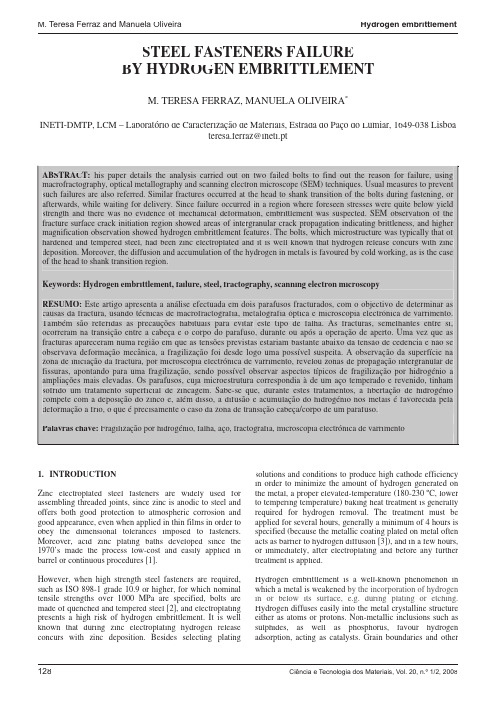
STEEL FASTENERS FAILUREBY HYDROGEN EMBRITTLEMENTM. TERESA FERRAZ, MANUELA OLIVEIRA*INETI-DMTP, LCM – Laboratório de Caracterização de Materiais, Estrada do Paço do Lumiar, 1649-038 Lisboateresa.ferraz@ineti.ptABSTRACT:his paper details the analysis carried out on two failed bolts to find out the reason for failure, using macrofractography, optical metallography and scanning electron microscope (SEM) te tchniques. Usual measures to prevent such failures are also referred. Similar fractures occurred at th re head to shank transition of the bolts during fastening, or afterwards, while waiting for delivery. Since failure occurred in a region where foreseen stresses were quite below yield strength and there was no evidence of mechanical deformation, embrittlement was suspected. SEM observation of the fracture surface crack initiation region showed areas of inte rrgranular crack propagation indicating brittleness, and higher magnification observation showed hydrogen embrittlement features f. The bolts, which microstructure was typically that of hardened and tempered steel, had been zinc electroplated and it is well known that hydrogen release concurs with zinc deposition. Moreover, the diffusion and accumulation of the hydrogen in metals is fav oured by cold working, as is the case of the head to shank transition region.Keywords:Hydrogen embrittlement, failure, steel, fractography, scanning electron microscopyRESUMO:Este artigo apresenta a análise efectuada em dois parafusos fracturados, com o objectivo de determinar as causas da fractura, usando técnicas de macrofractografia, metalografia óptica e microscopia electrónica de varrimento. Também são referidas as precauções habituais para evitar este tipo de falha. As fracturas, semelhantes entre si, ocorreram na transição entre a cabeça e o corpo do parafuso, durante ou após a operação de aperto. Uma vez que as fracturas apareceram numa região em que as tensões previstas estariam bastante abaixo da tensão de cedência e não se observava deformação mecânica, a fragilização foi desde logo uma possível suspeita. A observação da superfície na zona de iniciação da fractura, por microscopia electrónica de varrimento, revelou zonas de propagação intergranular de fissuras, apontando para uma fragilização, sendo possível observar aspectos típicos de fragilização por hidrogénio a ampliações mais elevadas. Os parafusos, cuja microestrutura correspondia à de um aço temperado e revenido, tinham sofrido um tratamento superficial de zincagem. Sabe-se que, durante estes tratamentos, a libertação de hidrogénio compete com a deposição do zinco e, além disso, a difusão e acumulação do hidrogénio nos metais é favorecida pela deformação a frio, o que é precisamente o caso da zona de transição cabeça/corpo de um parafuso.Palavras chave:Fragilização por hidrogénio, falha, aço, fractografia, microscopia electrónica de varrimento1.INTRODUCTIONZinc electroplated steel fasteners are widely used for assembling threaded joints, since zinc is anodic to steel and offers both good protection to atmospheric corrosion and good appearance, even when applied in thin films in order to obey the dimensional tolerances imposed to fasteners. Moreover, acid zinc plating baths developed since the 1970’s made the process low-cost and easily applied in barrel or continuous procedures [1].However, when high strength steel fasteners are required, such as ISO 898-1 grade 10.9 or higher, for which nominal tensile strengths over 1000 MPa are specified, bolts are made of quenched and tempered steel [2], and electroplating presents a high risk of hydrogen embrittlement. It is well known that during zinc electroplating hydrogen release concurs with zinc deposition. Besides selecting plating solutions and conditions to produce high cathode efficiency in order to minimize the amount of hydrogen generated on the metal, a proper elevated-temperature (180-230 ºC, lower to tempering temperature) baking heat treatment is generally required for hydrogen removal. The treatment must be applied for several hours, generally a minimum of 4 hours is specified (because the metallic coating plated on metal often acts as barrier to hydrogen diffusion [3]), and in a few hours, or immediately, after electroplating and before any further treatment is applied.Hydrogen embrittlement is a well-known phenomenon in which a metal is weakened by the incorporation of hydrogen in or below its surface, e.g. during plating or etching. Hydrogen diffuses easily into the metal crystalline structure either as atoms or protons. Non-metallic inclusions such as sulphides, as well as phosphorus, favour hydrogen adsorption, acting as catalysts. Grain boundaries and otherlattice defects are also regions where hydrogen diffuses and accumulates easily, hence preferential for hydrogen embrittlement to occur. Hydrogen diffusion is also easier in all regions where the crystalline structure may be distorted as a result of work hardening or cold deformation. The accumulation of hydrogen restricts ductility and promotes brittleness.Hardened and tempered steels need only a few p.p.m. of hydrogen to cause embrittlement [3, 4].F ailure induced by hydrogen is favoured or caused by applied stresses, even static or of low intensity, and is often referred to as “delayed” or “retarded”, since it may not take place immediately after tensile stresses are applied. This type of embrittlement is not detectable by hardness determinations, but tensile tests will show considerable reduction of the expected tensile strength of the material [5].This work presents a case study where premature fragile failure of several bolts occurred, during assembly of components, or afterwards while waiting for delivery (delayed failure), at low stresses, quite below the specified proof stress.2.FAILURE ANALYSISThe fractures occurred at the head to shank transition of several steel fasteners used to fix an engine to its base. The following items and information were provided for failureanalysis:-Photographs of a component with a fractured bolt inside and of two fractured bolts (Fig. 1); -two fractured bolts (head and shank);-bolts were supposed to be class 10.9 (ISO 898-1) and zinc electroplated.Fig. 1. General view of two fractured boltsPreliminary visual inspection of the fractured bolts showed f that:-All bolts failed in a similar way;-fractured surfaces were similar and the rupture hadoccurred apparently without necking (plasticdeformation) in the transition zone between head and shank;-there was no general oxidation and/or corrosion;-fracture surfaces were quite smooth and normal to the direction of the applied loads, except for the central part corresponding to the end of fracture;-fractures seemed to have had its origin all around the circular external bolt surface, where several initiating zones were observed.The following tests were carried out:-Fractographic examination of both bolts fracture surfaces at low magnifications (3 to 20 times) with an optical stereomicroscope and also at higher magnification with a SEM (20 to 10000 times) after ultrasonic cleaning in an ethylic alcohol bath.-Metallographic examination by optical microscopy of the fractured bolts microstructure on longitudinal sections from the head and shank part nearest to the head taken through the bolt axis.-Rockwell C hardness determinations on a cross section of the shank.3.RESULTS 3.1.F RACTOGRAPHYObservations at low magnification (Fig. 2) showed that:-Fracture characteristics were similar in both bolts indicating that failure must have occurred by the same causes;-the fractures were almost parallel to the cross section, and occurred with no evidence of deformation or distortion near the origin;-the fracture surfaces were nearly flat with several crack initiation zones all around the external bolt surface;-origins were located at slightly different levels and after a short propagation cracks joined together in a common front;-the fracture surface area corresponding to this first stage of propagation showed the smoothest surface on fig. 2 b) and 2 c);-cracks continued to propagate towards the centre, and fracture surfaces became rougher;-final rupture occurred by overload shear and showed a change in crack propagation direction towards the top of the bolt head;-both fractures occurred almost instantaneously after cracking initiation due to the applied stresses.a)b)c)Fig. 2. F ractured bolt: a) General side view of facture surface, shank side; b) details of fracture initiation zones at head-shank transition surface, shank side; c) details of fracture initiation zones at head-shank transition surface,head side.SEM allowed further information about surface fracture features (Fig. 3, 4 and 5): -Cracking initiation zones and zones near the surface presented both intergranular and transgranular crack propagation;-crack growth zones showing intergranular features also presented intercrystalline subsidiary cracking (or yawning grain boundaries), and micro-pores and ductile hair lines, oftenbranched forming crow feet marks, at prior austenite grain boundaries [6];-intergranular fracture surfaces zones showed some small areas, looking like nests, where intercrystallinecharacteristics are more pronounced as grains seemedmore individualized;-at the end of the propagation failure process, close to the centre of the bolts, the fracture surface showed a typical dimpled configuration with elongated cavities (fig. 5);a)b)Fig. 3.SEM observation of one of the bolts fracture surfaces: a) overall view of initiation zones near shank external surface; b) detail from marked area, fracture propagation partially intercrystalline and transcrystalline, intergranular zones showing intercrystalline subsidiary cracking, micro-pores and ductile hair lines at the former austenite grain boundaries.Inita)b)c)d)Fig. 4.SEM observation of the other bolt fracture surfaces:a) and c) general view at the initiation zone near the externalsurface of the shank; b) and d) details from marked zoneswith pronounced intercrystalline characteristics showinggrain surface features like micro-pores and ductile hair linesat the former austenite grain boundaries.Fig. 5.SEM observation of fractured surfaces: dimpledrupture fracture surface at final rupture zone near bolt centre3.2.O PTICAL MICROSCOPYMetallographic examination of the longitudinal sectionsfrom the head and the shank showed the typicalmicrostructure of hardened and tempered steel, with novisible external surface decarburization (Fig. 6) orcontinuous carbide precipitation along grain boundaries(Fig. 7).Fig. 6. Metallography of the shank cross section: externalsurface and initiation of fracture zone from the fracturesurfaceAt the initiation zone, fracture surface was flat and rathersmooth and there was no fracture branching neither oxidesdeposits nor decarburization over the fracture surface. Somesmall intercrystalline subsidiary cracking was detected onfracture surface grains.There were several inclusions of the sulphide (type A) andoxide (type D) types, but always below the 2 ½ index of theJK chart (plate I ASTM E45) for type A inclusions andbelow 1 ½ for type D.Few non-metallic inclusions appeared cracked or debondedfrom the matrix, indicating lack of ductility. F ig. 7exemplifies one agglomerate of inclusions, cracked anddebonded from the matrix, and seeming to originate amicro-crack, almost 50 ȝm long, with rather sharp tips.Fig. 7.Metallography of the shank cross section just below fracture surface: sulphide and oxide non metallic inclusions and a set of cracked and/ or debonded inclusions, resulting into a micro crack.3.3.R OCKWELL HARDNESSThe determinations were carried out at a cross section cut at approximately 1,5cm from the end of the thread. The average value obtained was 36,2 ± 3,1 HRC (95% mean confidence level), value which is within the range specified for grade 10.9 bolts (32 to 39 HRC, after ISO 898-1 [2]).4.DISCUSSIONThe failure analysis here reported involves high strength steel fasteners grade 10.9 [2], heat treated (quenched and tempered), in order to achieve the specified high strength levels. The hardness values determined were in the range specified for this class of bolts (class 10.9, 32 to 39 HRC).The flatness of fracture surfaces, the serial failures and the fact that failure process took place in a region where, whenin service, expected tensile stresses are considerably lower (at least twice to three times lower) than those expected after fastening in the threaded shank zone at the first thread inside the nut, pointed out to a manufacture or material defect or to an embrittlement phenomenon as causes for failure.The microstructure observed corresponded to hardened and tempered steel, without detectable preferential carbide precipitation along previous austenite grain boundaries, so carbide embrittlement was excluded. Surface decarburization was not detected either.Inclusion content of the steel was far below the maximum limits accepted for this kind of application. F orging defects,fcracks or other discontinuities,that could have acted as stress concentrators or raisers were also not observed. Finally, there was not oxidation of the fracture surface, or crack branching along grain boundaries, which would indicate quenching cracking or a stress corrosion crack process.The observation of the fracture surfaces carried out in the SEM showed that, starting at the external surface, crack growth occurred intergranularly, indicating embrittlement. Typical features of hydrogen embrittlement were observed in the fracture surfaces of both bolts, as described above. Bolts manufacturing process can produce highly non-uniform deformation, as shown in F ig. 8. The head region and in particular the head/shank interface can undergosignificant cold work hardening raising the tensile strength in these regions considerably in excess of the 1000 MPa [4] specified. At these high strength levels, subsequent electroplating brings a serious risk of hydrogen embrittlement. The deformed microstructure which resulted from the manufacturing process, highly distorted and having high concentration of lattice defects like vacancies and dislocations, favours the diffusion and concentration of the hydrogen released during electroplating.Fig. 8. Bolts c ross section macrostructure showing the deformation lines produced by head forging due to non-uniform deformationThe diatomic hydrogen molecule is too large to enter the surface of a solid metal and diffuse interstitially. However, in the dissociated form, single atoms are relatively mobile, even at room temperature [4]. One way to produce atomic hydrogen is the cathode reaction competing with metal deposition in an electroplating process (equations (1) and (2)):Zn2++ 2e- = Zn0 (1)2 H+ + 2e- = H2 (2)Therefore, the electrolytic process must be controlled, namely high efficiency procedures must be used, current intensity and bath impurities controlled and good agitation provided in order to liberate the hydrogen bubbles formed over the cathode surface. The control may not always be efficient in order to prevent hydrogen from concentrating in microstructure defects and some hydrogen may be inevitably present.The solubility of hydrogen decreases with temperature and hydrogen accumulated in lattice defects may precipitate in gaseous form, originating a pressure high enough to produce small cracks. This can however be avoided by a post plating baking treatment to remove hydrogen prior to service [3,4]. Zinc electroplated components must undergo the treatment at temperatures around 200o C, for several hours and immediately or shortly after plating.Internal hydrogen embrittlement has been known for years, but is far away from being banished or even controlled. Some components may require longer baking times due tomore gas evolution during plating or to thicker and less permeable coatings. To prevent risk of failure due to improper baking after electroplating, standardized tests on samples may be conducted [7,8]. Another alternative is to choose a coating procedure without hydrogen embrittlement risk.5.CONCLUSIONSHydrogen embrittlement remained as the only probable cause of the failure observed. Unlike stress corrosion cracking and quenching cracks, cracks caused by hydrogen embrittlement usually do not branch [3] neither show oxidized surfaces. Typical features of hydrogen embrittlement were observed on the fracture surfaces of both bolts.Bolts had been zinc electroplated, which is one way to introduce hydrogen into metals, and baking treatment after plating may not have been well conducted. ACKNOWLEDGEMENTSThe authors thank LCM collaborators Maria Pinho (metallographic preparation), Paulino Verdasca (hardness tests) and also Susana Dias, M.Sc, (scanning electron microscopy).6.REFERENCES[1]Geduld, H.H., “Zinc Plating”, in “Metals Handbook”,Ninth Edition, Vol. 5, 244-255, American Society forMetals, Metals Park, Ohio, U.S.A. (1982). [2]ISO 898-1:1999, “Mechanical properties of fastenersmade of carbon steel and alloy steel – Part 1: Bolts,screws and studs.[3]Kim, C.D., “Hydrogen-Damage F ailures”, in “MetalsHandbook”, Ninth Edition, Vol 11, 245-251, AmericanSociety for Metals, Metals Park, Ohio, U.S.A. (1986). [4]T.J. Carter, L.A. Cornish, “Hydrogen in metals”,Engineering Failure Analysis, 8 (2001) 113-121.[5]Trowsdale, A.J. and Pritchard, S. B., “Dual phase steel– High strength fasteners without heat treatment”, Corus Construction& Industrial, UK, InternalCommunication.[6]Engel, L. and Klingele H., “Damage mechanisms andtheir appearance – Fracture caused by combinations ofmechanical loading and chemical attack” chapter 3, pp. 105-132 in “An atlas of metal damage- surfaceexamination by scanning electron microscope”translated by Stuart Murray ed. Wolfe Science Booksin association with Carl Hanser Verlag, Munich, Vienna, 1984.[7]ASTM F 1940-07a “Standard Test Method for ProcessControl Verification to Prevent HydrogenEmbrittlement in Plated or Coated Fasteners”[8]ISO 15330:1999 “F asteners – Preloading test for thedetection of hydrogen embrittlement – Parallel bearingsurface method”。
氢脆

氢脆氢脆(hydrogen embrittlement)是指金属材料在冶炼、加工、热处理、酸洗和电镀等过程中,或在含氢介质中长期使用时,材料由于吸氢或氢渗而造成机械性能严重退化,发生脆断的现象.人们不仅在普通的钢材中发现氢脆现象,在不锈钢、铝合金、钛合金、镍基合金和锆合金中也都有此现象.从机械性能上看,氢脆有以下表现:氢对金属材料的屈服强度和极限强度影响不大,但使延伸率是断面收缩率严重下降,疲劳寿命明显缩短,冲击韧性值显著降低。
在低于断裂强度拉伸应力的持续作用下,材料经过一段时期后会突然脆断。
氢脆的机理氢脆的机理学术界还有争议,但大多数学者认为以下几种效应是氢脆发生的主要原因:•在金属凝固的过程中,溶入其中的氢没能及时释放出来,向金属中缺陷附近扩散,到室温时原子氢在缺陷处结合成分子氢并不断聚集,从而产生巨大的内压力,使金属发生裂纹.•在石油工业的加氢裂解炉里,工作温度为300-500度,氢气压力高达几十个到上百个大气压力,这时氢可渗入钢中与碳发生化学反应生成甲烷.甲烷气泡可在钢中夹杂物或晶界等场所成核,长大,并产生高压导致钢材损伤.•在应力作用下,固溶在金属中的氢也可能引起氢脆.金属中的原子是按一定的规则周期性地排列起来的,称为晶格.氢原子一般处于金属原子之间的空隙中,晶格中发生原子错排的局部地方称为位错,氢原子易于聚集在位错附近.金属材料所外力作用时,材料内部的应力分布是不均匀的,在材料外形迅速过渡区域或在材料内部缺陷和微裂纹处会发生应力集中.在应力梯度作用下氢原子在晶格内扩散或跟随位错运动向应力集中区域.由于氢和金属原子之间的交互作用使金属原子间的结合力变弱,这样在高氢区会萌生出裂纹并扩展,导致了脆断.另外,由于氢在应力集中区富集促进了该区域塑性变形,从而产生裂纹并扩展.还有,在晶体中存在着很多的微裂纹,氢向裂纹聚集时有吸附在裂纹表面,使表面能降低,因此裂纹容易扩展.•某些金属与氢有较大的亲和力,过饱和氢与这种金属原子易结合生成氢化物,或在外力作用下应力集中区聚集的高浓度的氢与该种金属原子结合生成氢化物.氢化物是一种脆性相组织,在外力作用下往往成为断裂源,从而导致脆性断裂.如何防止氢脆氢脆给人类利用金属带来了风险,因此研究氢脆的目的主要在于防止氢脆,由于氢脆的原因很多,而且人类的认识也不够透彻完整,所以现在还无法完全防止氢脆.目前防止氢脆的措施有以下几种:•避免过量氢带入--在金属的冶炼过程中降低相对湿度,对各种添加剂和钢锭模进行烘烤保持干燥.•去氢处理--减缓钢锭冷却速度使氢有足够的时间逸出,或把钢材放在真空炉中退火除氢.•钢中添加适当的合金元素,形成弥散分布的第二相,做为氢的不可逆陷阱,使得材料中的可活动氢的含量相对地减少,从而降低材料的氢脆倾向.•发展新的抗氢钢种,氢在体心立方晶体结构中的扩散速度比六角密堆结构或面心立方结构中的扩散速度高得多,所以抗氢钢常以具有面心立方结构的相为基,再加其他强化措施,可使其满足使用强度要求.•采用适当的防护措施--在酸洗或电镀时在酸液或电解液中添加缓蚀剂,使溶液中产生的大量氢原子在金属表面相互结合成氢分子直接从溶液中逸出,避免氢原子进入金属内部.•此外,在构件外涂敷防腐层或在工作介质中施加保护电位,可避免构件与介质反应生成氢.。
HIC氢脆原因分析及氢脆名词解释

HIC氢脆原因分析及氢脆名词解释氢脆氢脆是溶于钢中的氢,聚合为氢分子,造成应力集中,超过钢的强度极限,在钢内部形成细小的裂纹,又称白点。
氢脆只可防,不可治。
氢脆一经产生,就消除不了。
在材料的冶炼过程和零件的制造与装配过程(如电镀、焊接)中进入钢材内部的微量氢(10的负6次方量级)在内部残余的或外加的应力作用下导致材料脆化甚至开裂。
在尚未出现开裂的情况下可以通过脱氢处理(例如加热到200℃以上数小时,可使内氢减少)恢复钢材的性能。
因此内氢脆是可逆的。
中文名:氢脆外文名:Hydrogen embrittlement拉丁文名:Hydrogenium embrittlement解释:溶于钢中的氢聚合形态:氢分子作用:超过钢的强度极限1、氢脆的机理学术界还有争议,但大多数学者认为以下几种效应是氢脆发生的主要原因:在金属凝固的过程中,溶入其中的氢没能及时释放出来,向金属中缺陷附近扩散,到室温时原子氢在缺陷处结合成分子氢并不断聚集,从而产生巨大的内压力,使金属发生裂纹.在石油工业的加氢裂解炉里,工作温度为300-500度,氢气压力高达几十个到上百个大气压力,这时氢可渗入钢中与碳发生化学反应生成甲烷.甲烷气泡可在钢中夹杂物或晶界等场所成核,长大,并产生高压导致钢材损伤.在应力作用下,固溶在金属中的氢也可能引起氢脆.金属中的原子是按一定的规则周期性地排列起来的,称为晶格.氢原子一般处于金属原子之间的空隙中,晶格中发生原子错排的局部地方称为位错,氢原子易于聚集在位错附近.金属材料受外力作用时,材料内部的应力分布是不均匀的,在材料外形迅速过渡区域或在材料内部缺陷和微裂纹处会发生应力集中.在应力梯度作用下氢原子在晶格内扩散或跟随位错运动向应力集中区域.由于氢和金属原子之间的交互作用使金属原子间的结合力变弱,这样在高氢区会萌生出裂纹并扩展,导致了脆断.另外,由于氢在应力集中区富集促进了该区域塑性变形,从而产生裂纹并扩展.还有,在晶体中存在着很多的微裂纹,氢向裂纹聚集时有吸附在裂纹表面,使表面能降低,因此裂纹容易扩展.某些金属与氢有较大的亲和力,过饱和氢与这种金属原子易结合生成氢化物,或在外力作用下应力集中区聚集的高浓度的氢与该种金属原子结合生成氢化物.氢化物是一种脆性相组织,在外力作用下往往成为断裂源,从而导致脆性断裂.工业管道的氢脆现象可发生在实施外加电流阴极保护的过程之中:现阶段为了防止金属设备发生腐蚀,一般大型的工业管道都采用外加电流的阴极保护方式,但是这种方式也能引发杂散电流干扰的。
应力腐蚀和氢脆

模块二 氢 脆
能力知识点1 氢脆和氢的来源
一、什么是氢脆
氢脆(Hydrogen embrittlement —HE) 又称氢致开裂或氢 损伤,是由于氢和应力的共同作用而导致金属材料产生塑 性下降、断裂或损伤的现象。
从力学性能上看,氢脆有以下表现: 氢对金属材料的强度指标影响不大,但使断面收缩率严重 下降,疲劳寿命明显缩短,冲击韧性值显著降低,在低于 断裂强度的拉伸应力作用下,材料经过一段时期后会突然 脆断。
▪ 应力腐蚀的主裂纹扩展时常有分枝。但不要形成绝对化 的概念,应力腐蚀裂纹并不总是分枝的。
▪ 应力腐蚀破坏的断口,其颜色灰暗,表面常有腐蚀产物 (泥状花样),或腐蚀坑。而疲劳断口的表面,如果是 新鲜断口常常较光滑,有光泽。
▪ 应力腐蚀引起的断裂可以是穿晶断裂,也可以是沿晶断 裂。如果是穿晶断裂,其断口是解理或准解理的,其裂 纹有似人字形或羽毛状的标记。
镍基合金
热浓NaOH溶液,HF溶 液和蒸汽
发烟硝酸,300℃以上 钛合金 的氯化物,潮湿性空气
及海水
▪ (3)一般认为,纯金属不会产生应力腐蚀,所有合金对应 力腐蚀都有不同程度的敏感性,合金也只有在拉伸应力与 特定腐蚀介质联合作用下才会产生应力腐蚀断裂。
但在每—种合金系列中,都有对应力腐蚀敏感的合金 成分。例如,铝镁合金中当镁的质量分数大于4%,对应力 腐蚀很敏感;而镁的质量分数小于4%时,则无论热处理条 件如何,它几乎都具有抗应力腐蚀的能力。
▪ 当KⅠ值降低到某一临界值(图中为38MPa.m1/2) 时,应力腐蚀开裂实际上就不发生了。这一KⅠ 值称之为应力腐蚀临界场强度因子,也称应力
腐蚀门槛值,以 KⅠSCC表示(SCC表示应力腐蚀 断裂)。
应力腐蚀临界应力场强度因子KISCC
氧化处理(发黑=发蓝)——read
螺栓氧化处理实际上螺栓氧化处理会出现轻微的氢脆,只是出现的不那么明显,一般情况不会影响使用。
科技名词定义中文名称:氢脆英文名称:hydrogen embrittlement 其他名称:白点定义1:金属由于吸氢引起韧性或延性下降的现象。
应用学科:船舶工程(一级学科);船舶腐蚀与防护(二级学科)定义2:钢材在冶炼、加工和使用中溶解于钢中的原子氢,在重新聚合成分子氢时产生的巨大应力超过钢的强度极限时,可以在钢内产生微裂纹,导致材料的韧性或塑性下降的现象。
氢脆是溶于钢中的氢,聚合为氢分子,造成应力集中,超过钢的强度极限,在钢内部形成细小的裂纹,又称白点。
氢脆只可防,不可治。
氢脆一经产生,就消除不了。
在材料的冶炼过程和零件的制造与装配过程(如电镀、焊接)中进入钢材内部的微量氢(10—6量级)在内部残余的或外加的应力作用下导致材料脆化甚至开裂。
在尚未出现开裂的情况下可以通过脱氢处理(例如加热到200℃以上数小时,可使内氢减少)恢复钢材的性能。
因此内氢脆是可逆的。
没有经过酸洗不会氢脆。
通用防锈热处理,使钢材表面生成致密氧化膜,如零件的发黑,发蓝处理,均为表面氧化.氧化膜就是利用化学物质高温使螺栓表面形成一种无形的氧化膜,起保护作用,具体就是防锈用的,起点润滑作用表面氧化处理是利用强氧化剂在金属表面形成一层致密的氧化层。
防止了金属内部的氧化,就可以达到耐腐蚀和抗氧化的效果。
发黑发兰处理,就是一种氧化处理电镀和氧化。
电镀是装饰性表面处理,氧化是装饰表面处理和防腐处理。
假设螺栓是钢材,镀锌钝化最佳。
如果是铝材的就用氧化方法来提高防腐。
镀锌是在金属表面镀上一层锌后再做钝化皮膜来提高其防腐性,发黑也是用来提高防腐,但防腐能力不如镀锌好,氧化多数是针对铝材来处理的,提高防腐性能。
铁材螺栓电镀锌的盐雾最好,纯铝材的氧化也还好。
发黑一般都是铁材的表面处理,工作环境为油性时才选择这样的处理,优点不影响尺寸,缺点盐雾较差,干燥时易生锈。
钛合金氢脆的失效分析

钛合金氢脆的失效分析本页仅作为文档封面,使用时可以删除This document is for reference only-rar21year.March钛合金氢脆的失效分析摘要:氢脆是钛合金在使用过程中失效的主要原因之一,它严重影响着钛合金的生产和应用。
本文主要介绍了钛合金氢脆的机理、影响因素、预防措施及应用等进行了阐述,并对存在的问题和发展前景进行探讨。
关键词:钛合金,氢脆,机理,影响因素,预防措施Failure analysis of titanium alloys to hydrogen embrittlement ABSTRACT:Hydrogen embrittlement is one of the main reasons for failure of titanium alloy in the course of it a serious impact on the titanium alloy production and applications. This paper describes the mechanism of the titanium alloy to hydrogen embrittlement, influencing factors, preventive measures and applications are described and the problems and prospects to explore.KEY WORDS:Titanium alloys, hydrogen embrittlement, influencing factors, preventive measures引言由于钛合金优良的比强度、刚性和耐腐蚀性能以及它们在高温下的良好性能,而成为广泛地用于航空、航天、化工、石油、冶金、轻工、电力、海水淡化、舰艇和日常生活器具等工业生产中,被誉为现代金属[1]。
氢脆的检测

氢脆的检测氢脆的检测英文名称:hydrogen embrittlement 其他名称:白点定义1:金属由于吸氢引起韧性或延性下降的现象。
所属学科:船舶工程(一级学科);船舶腐蚀与防护(二级学科)定义2:钢材在冶炼、加工和使用中溶解于钢中的原子氢,在重新聚合成分子氢时产生的巨大应力超过钢的强度极限时,可以在钢内产生微裂纹,导致材料的韧性或塑性下降的现象。
氢脆是溶于钢中的氢,聚合为氢分子,造成应力集中,超过钢的强度极限,在钢内部形成细小的裂纹,又称白点。
氢脆只可防,不可治。
氢脆一经产生,就消除不了。
在材料的冶炼过程和零件的制造与装配过程(如电镀、焊接)中进入钢材内部的微量氢(10—6 量级)在内部残余的或外加的应力作用下导致材料脆化甚至开裂。
在尚未出现开裂的情况下可以通过脱氢处理(例如加热到200℃以上数小时,可使内氢减少)恢复钢材的性能。
因此内氢脆是可逆的。
热处理不适用的情况热处理的方法是将工件加热至某一温度,保温一段时间,缓冷,使氢随溶解度逐渐变小,逐渐析出。
但加热会破坏镀层,因此热处理的方法对于经过电镀的工件并不适用。
如何防治首先,尽量缩短酸洗时间;其次加缓蚀剂,减少产氢量。
压力容器的氢脆(或称氢损伤)是指它的器壁受到氢的侵蚀,造成材料塑性和强度降低,并因此而导致的开裂或延迟性的脆性破坏。
高温高压的氢对钢的损伤主要是因为氢以原子状态渗入金属内,并在金属内部再结合成分子,产生很高的压力,严重时会导致表面鼓包或皱折;氢与钢中的碳结合,使钢脱碳,或使钢中的硫化物与氧化物还原。
造成压力容器氢脆破坏的氢,可以是设备中原来就存在的,例如,炼钢、焊接过程中的湿气在高温下被还原而生成氢,并溶解在液体金属中。
或设备在电镀或酸洗时,钢表面被吸附的氢原子过饱和,使氢渗入钢中;也可以是使用后由介质中吸收进入的,例如在石油、化工容器中,就有许多介质中含氢或含混有硫化氢的杂质。
钢发生氢脆的特征主要表现在微观组织上。
它的腐蚀面常可见到钢的脱碳铁素体,氢脆层有沿着晶界扩展的腐蚀裂纹。
加氢设备损伤模式、机理、影响因素、防范方法
加氢设备损伤模式、机理、影响因素、防范方法加氢是什么?加氢技术包括加氢裂化和加氢精制。
加氢裂化使重质化的原油裂化为轻质油(汽油、柴油、煤油及制烯烃的原料等)。
加氢精制通过将油品中的硫、氧、氮等有害杂质转化为硫化氢、水、氨而将其除去。
通过加氢技术,我们将劣质化、重质化的原油,转化成优质化、轻质化的油品。
由于加氢要在高温高压临氢的苛刻环境下进行,且有的进料物流中还含有硫化氢、氨等腐蚀性介质,设备是非常容易损伤的。
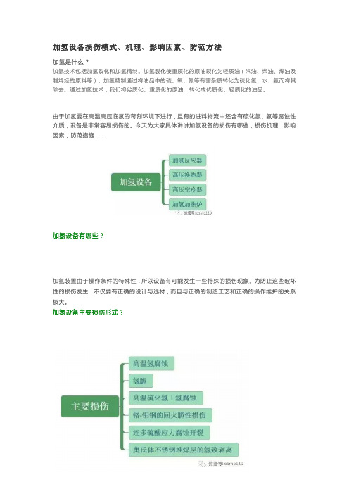
今天为大家具体讲讲加氢设备的损伤有哪些,损伤机理,影响因素,防范措施......加氢设备有哪些?加氢装置由于操作条件的特殊性,所以设备有可能发生一些特殊的损伤现象。
为防止这些破坏性的损伤发生,不仅要有正确的设计与选材,而且与正确的制造工艺和正确的操作维护的关系极大。
加氢设备主要损伤形式?高温氢腐蚀HA—Hydrogen Attack高温氢腐蚀的形式有两种。
表面脱碳表面脱碳不产生裂纹,表面脱碳的影响一般很轻,其钢材的强度和硬度局部有所下降而延展性提高。
内部脱碳与开裂内部脱碳是由于氢扩散侵入到钢中发生反应生成甲烷,即:甲烷聚集于晶界空穴和夹杂物附近,形成很高的局部应力,使钢材产生龟裂、裂纹或鼓泡,并使钢材强度和韧性显著下降。
由于这种损伤是发生化学反应的结果,所以它具有不可逆的性质,也称永久脆化现象。
其实际的进展是甲烷气泡在晶界形核、成长及气泡串通产生晶间微裂纹,最终这些微裂纹能够连通而形成断裂通道。
孕育期这里要引出一个“孕育期”(或称潜伏期)的概念。
就是对于处在形成甲烷气泡,但成长速度缓慢且没有串通的阶段,钢材的力学性能不发生明显改变的这段时间称为“孕育期”。
“孕育期”的概念对于工程上的应用是非常重要的。
它可被用来确定设备和管道所采用的钢材的大致安全使用时间。
“孕育期”的长短取决于许多因素,包括钢种、氢压、温度、冷作程度、杂质元素含量和作用应力等。
影响高温氢腐蚀的主要因素●温度、压力和暴露时间的影响操作温度越高,钢材氢腐蚀越严重。
- 1、下载文档前请自行甄别文档内容的完整性,平台不提供额外的编辑、内容补充、找答案等附加服务。
- 2、"仅部分预览"的文档,不可在线预览部分如存在完整性等问题,可反馈申请退款(可完整预览的文档不适用该条件!)。
- 3、如文档侵犯您的权益,请联系客服反馈,我们会尽快为您处理(人工客服工作时间:9:00-18:30)。
embrittlement in a given test is directly related to the characteristics of its trap population. In this instance, trap population relates to the material microstructure, dislocations, carbides and other elements present in the structure. Such is the effect that interactions can be reversible or irreversible sources. Diffusion is controlled by the rate of escape of hydrogen from the traps; the nature and the density of the traps control the diffusion coefficients.The greater the hydrogen concentration becomes, the lower the critical stress, or lower the hydrogen concentration, the higher the critical stress at which failure may occur.Hydrogen embrittlement is non-corrosion related. It is interrelated to high hardness values of the component part. Products having Vickers hardness exceeding HV 320 require special care to reduce the risk of this phenomenon during the plating process or coating procedures. Some experts feel that hardness exceeding HV390 is a threshold beyond which further steps to manage hydrogen embrittlement risk are required, often ensuring that acid is not used in the cleaning process, in our view, this would be prudent. event, stress relieving will be required for high hardness parts to relieve built-in stress.The vast majority of processing embrittlement risk appears to be attributed to electroplating process. Before electroplating can take place, parts have to be chemically clean with an active surface. The cleaning process is typically alkaline degreasing followed by acid pickling to remove heat treatment scale, rust and other oxide films. Acid pickling produces nascent hydrogen, so it is advisable, and often mandated in specifications, that this should be kept to a minimum time. Alternatives such as alkaline de-scaling, a slow and expensive process, or mechanical cleaning can be used, and often must be used for cleaning very high tensile components. The other major source of hydrogen is from the actual electroplating solution. Up until a few years ago, the vast majority of plating baths employed cyanide as an electrolyte. Thus, zinc-cyanide solutions and cadmium-cyanide were commonplace. As plating solutions are depleted, the efficiency will drop with a corresponding increase in hydrogen release. The development of non-cyanide electrolytes has resulted in acid-zinc and acid-cadmium operating in the 95% or higher efficiency range. This has reduced the generation of hydrogen significantly.There is, however, no guarantee that high efficiency gives no embrittlement. Low temperature heat treatment (baking) is required to reduce the risk.The structure of the coating from an acid solution has a laminar structure, which, due to its lack of porosity,does not allow hydrogen to diffuse from the surface readily. The advantage of a columnar structure, which is given by an alkaline solution, as opposed to laminar,allows the hydrogen to diffuse through the coating.Some plating specifications note this point and direct that only certain types of plating solutions should be used.The electroplating efficiency of a solution varies with the electrical current density, and in barrel plating, the barrel loading, the rotational speed, contact efficiency,solution temperature, etc. can affect results. So barrel loading is important to reduce hydrogen embrittlement risk.Thus, the manufacturer should work closely with the electro-plater to ensure risk reduction is achieved in prepared steps, for the plating process, and that process care and checks are in place to prevent over or under filling of plating barrels.Hydrogen embrittlement mechanisms are thought to be diffusion controlled and thus the effects of time delay before bake are very important.When high strength fasteners are involved, then no longer than one hour between plating to entry into the bake oven is often mandatory. The transfer time is important and governed by finishing rge bodies of evidence exist stating that delaysexceeding 4 hours following plating are detrimental to the effectiveness of baking.Depending upon product types, the baking time will vary from 2 hours for case hardened fasteners to 24hours for very high tensile or safety critical fasteners. Higher baking temperatures will increase diffusion rates and should improve de-embrittlement but there are risks of tempering back high tensile fasteners and also liquid metal embrittlement occurring, so baking temperatures of between 180°C and 220°C are usually recommended. Lower temperatures, and increased baking times, are required when this temperature affects the coating or the fastener material.Reference documents to consider for the de-embrittlement processes and other useful applicable information are listed.BS 7371 – Part 1:1991 Coating of metal fasteners.ISO 4042: 2000:Fasteners electroplated coatings.BS EN ISO 15330:1999 Preloading test for the detection of hydrogen embrittlement.BS EN ISO 20898-1:1999 Mechanical properties of fasteners. BS EN ISO 20898-2:1994 Mechanical properties of fasteners.Because residual and applied stresses are the drivers for hydrogen migration and interaction, it appears that higher strength (higher hardness) fasteners are more sensitive to any delays. The rapid transfer into the baking oven possibly reduces the opportunity for harmful hydrogen to begin its inward migration. It is the prevention of inward migration that will reduce the probability of embrittlement failure.Hydrogen Process Details Embrittlement RiskPreventative ActionDegreaseSolvent Alkali soak Electro cleanSome Only use anodically De-rust or De-scaleAcid High Use inhibited short time Alkaline de-rusts Low Poor at de-rustingAbrasive cleanNone Phosphate Acid process Medium Bake – reduces with timeElectro-platingAcid type Medium Bake Alkaline typeHighBakeTable 1. The Coating Process – Preventative Actions to Reduce Risks.A typical columnar structure.Problems occur when least expected. Good house-keeping is the key driver.Whist prediction is difficult, if the following rules are applied, then the risk should be minimised.s Mechanically clean the products if possible.s Mechanically plate high strength components.s Avoid any embrittling process if possible.s Use stringent baking control.Component parts should be to good design practice.Reviewing the following can reduce susceptibility to hydrogen embrittlement.s Ensuring sufficient ductility even at very high strength levels.s Limit content of detrimental elements,especially Sulphur and Phosphate.liability and recompense.This should motivate responsible suppliers to look for risk free solutions to these problems. Cost restraints have perhaps acted to restrain such solutions? This could be false economy for the unlucky victims of failures due to hydrogen embrittlement.The authors offer this information as best known practice and will not be held accountable for any liabilities that may result from the document.With acknowledgements to Clive D Pearce of the Anochrome Group for his assistance with this Data File.FERA17 Northwick CrescentSolihull West Midlands B91 3TU。