ACS 5000 产品介绍_draft
金智科技ePACS5000后台基本操作
UNIX系统后台基本操作目录一、开机二、关机三、后台运行四、遥控操作五、档位升降操作及档位急停六、遥测查询七、遥信查询八、报表查询九、曲线查询十、基本指令十一、添加信号十二、更改开关、刀闸编号一、开机使用主机正面开机键正常开机,开机时请耐心等待至画面出现输入用户名的界面,如下图用户名为epacs,口令为123456,(输入密码时,密码栏不显示,请注意)按回车键即可二、关机先将后台监控系统关掉,具体操作如下:在桌面上右键选择“主机”—〉“本主机”打开命令窗口,在命令窗口输入epacs_stop,按回车键,出现You will stop epacs system on this node.Are you sure?(y/n)时,直接敲入y,按回车键,等待一会后,会提示epacs_stop OK,此时后台监控软件关闭。
然后在命令窗口敲入su, 口令为root,(此步操作的意义是为了把系统用户切换为超级用户root),此时在窗口敲入init 5,回车,是关机;敲入reboot,回车,是电脑重启,请按需要选择。
如若出现死机状况,只能强行重启,即和普通机一样按住主机正面开机键一段时间,主机就会关机,等待几分钟之后正常开机即可三、后台运行正常开机后,在命令窗口敲入manager,回车,即可打开后台,输入用户和密码之后后台正常运行,如下图在桌面上有一“系统登录”的快捷方式,双击也可以打开后台系统四、遥控操作当后台监控系统正常运行时,打开“桥河110kV变电站一次系统接线图”,或者打开开关或者刀闸所在的间隔图,在需要进行遥控的开关或者刀闸上点击鼠标右键,在菜单中点击“遥控”,于是遥控过程开始。
其操作界面如图1所示。
图1如图2,遥控操作对话框的上端是被控对象的信息显示,主要有厂站名、测点名;中间部分是遥控方式、本控制是否需校验、遥控编号以及遥控过程信息显示框图2遥控过程依下面的步骤进行:◆输入遥控编号,遥控编号为开关或者刀闸本身的编号,例如上图编号即为2205;◆点击“遥控选择”,然后输入用户名、密码;在让用户输入用户名、密码之前,程序将自动进行防误校验,此时如果防误校验不通过,则直接提示防误校验失败而不再进行下去。
ABBACS5000中压变频器在重庆珞璜电厂的应用资料

ABB ACS5000中压变频器在重庆珞璜电厂的应用分析摘要:针对国内的电力迅猛发展,为进一步节能减排,提出了在电厂应用中压变频。
本文介绍了冷凝泵在电厂的运行工况,分析了水泵的变频节能原理。
对珞璜电厂的变频改造提出了系统方案,包括系统的动力方案和系统的控制方案。
着重介绍了ACS5000中压变频器的拓扑结构、技术特点和控制方式。
最后通过电厂的实测数据证明了ACS5000中压变频系统具有很高的系统动、静态性能,净节电率超过40%。
关键字:中压变频器;ACS5000;直接转矩控制;IGCT;电厂;冷凝泵Application Analysis of ABB ACS5000 MV Drives in Lu ohuang Power PlantGuan Eryong1, Peng Jingtao2, Jin Shi1, Wu Shaobin21. ABB Beijing drive systems Co., Ltd. 1000152. Chongqing Luohuang Power Plant of Huaneng group 402283Abstract:For the domestic development of electrical power, MV (medium voltage)drives are proposed in power pl ant to deeply save energy. This paper introduces th e operation condition of condensation pump and savin g principle with MV drives. A system scheme including system power scheme and system control scheme, i s put forward to retrofit the Luohuang power plant. This paper presents in detail the topology configu ration, technical feature and control scheme of ACS5 000 MV drives. According to the data in real runni ng derived from power plant, ACS5000 MV drives is verified to be with excellent static and dynamic pe rformance, and also save energy much more than 40%. Keyword:MV drives;ACS5000;DTC;IGCT;Power plant;Condensation pump1.引言(Introduction)随着国民经济的蓬勃发展,对于电力的需求日益增加,全国电力工业一直保持着快速增长的势头。
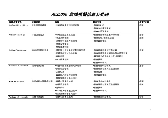
ACS5000报警及故障处理
S800 Module C1P4
S800模块C1P4故障
S800 Module C3P1
S800模块C3P1故障
S800 Module C3P2
S800模块C3P2故障
S800 Module C3P3
S800模块C3P3故障
-参数设置错误 -TB820不能正常工作
-S800调制故障 -S800接线端子单元损坏 -连线松动 -参数设置错误 -TB820不能正常工作
GUSP AuxPower
GUSP电源故障
-外部供电跳闸 -S800输入输出模块故障 -S800接线端子单元损坏
HV DC ChrgRelay INV CubicleOvTemp
高压直流充电继电器故 障
逆变柜温度过高ຫໍສະໝຸດ -高压充电继电器损坏 -参数设置错误 -连线松动 -环境温度过高
-将变频器接地,打开柜门检查有无烟雾,气味和 烧焦的器件 -检查与MCB控制接口有关的参数设置 -检查充电单元 -检查充电电路 -检查DC电压测量值 -在正常运行状态检查相间电压确保供电正常 -检查充电单元 -检查高压继电器 -检查S800模块 -检查参数设置 -检查放电电路 -检查参数设置 -检查上位机信号 -检查PFF链接信号 -检查接地刀闸是否接地 如接地,将接地分开 如未接地,关闭所有的门后,再将接地刀闸分开 -检查外部供电 -检查欠压检测器件 -检查GUSP电源 -检查辅助电源 -检查连线 -检查参数设置 -检查充电单元 -检查高压继电器 -检查S800模块 -检查环境温度,如果环境温度过高检查环境冷却
-检查外部辅助供电 -检查辅助电源欠压监视器件 -检查接线 -检查S800模块
-检查外部辅助供电
报警/故障 故障 报警 故障
可编程控制器罗克韦尔RSLogix5000介绍
第二章RSLogix5000编程学习目标:■学会创建任务、程序、例程■深入理解标签、结构体和数组■掌握编写梯形图程序■学习I/O组态方法■掌握RSLogix5000功能块图编程122.1 编写RSLogix5000梯形图2.1.1 创建任务、程序和例程本次课程基于一个假想的工业环境。
您是一位压缩机装配项目程序开发人员。
图2-1描述了压缩机装配项目的整个工艺流程。
在该项目中,传送带上的压缩机经过三个装配站:冲压、卷边和焊接。
然后,压缩机被传送到第二个传送带并接受质量检查。
通过检查的压缩机码垛后装船运走。
图2-1 工艺流程图冲压、卷边和焊接三个装配站和传送带1由控制器P1控制,质量检查和码垛站以及传送带2由控制器P2控制。
图2-2给出了模拟各工作站运行时所用按钮和指示灯等离散量输入/输出点。
光眼检测到有部件放置到传送带上(PartSensor 由0变为1)后,站1、2和3顺序执行,然后传送带动作。
当光眼再次检测到有部件送至传送带上,上述操作再次执行,以此循环。
下面我们以时序图方式描述控制器P1的操作流程,如图2-3所示。
本实验主题:● 创建并组态一个控制器项目 ● 创建任务 ● 组态任务属性 ● 创建程序● 编辑程序排列表 ● 创建例程 ● 分配例程PartSensor 光眼检查码垛焊接卷边冲压3图2-2 各个按钮和指示灯的含义在了解了装配线工艺流程及控制器P1操作流程之后,您对项目主管说可以开始为控制器P1编程了,这让他感到很惊讶,因为以前都是在完成电气设计之后才能够编写控制程序。
在听过您的解释之后,他认为并行设计的方案是可行的。
同时,他也提醒你,如果该生产线效果良好,公司可能会再增加一条生产线,但控制器可能还是使用现有的ControlLogix 控制器,希望你在编程时考虑到这个问题。
Press 站工作中 StationActive光眼检测输入 PartSensorStake 站工作中 StationActiveWeld 站工作中StationActive光眼故障指示 Part_Sensor_Fault_Indicator传送带输出 ConveyorOutput(P1) 检查站工作中 StationActive码垛站工作中 StationActive检查通过 PartPASSED检查未通过 PartFAULT传送带输出ConveyorOutput(P2)光眼检测PartSensorPress站工作中StationActiveStake站工作中StationActiveWeld站工作中StationActive传送带输出ConveyorOutput(P1)图2-3 时序图实验步骤:1.双击桌面上图标,打开RSLogix5000软件,如图2-4所示。
EC5000
EC5000电子调速板使用说明目录1. 主要特征 (2)2. 产品描述 (2)3. 性能尺寸规格接线图 (3)4. 安装指南 (4)5. 使用前设置 (4)6. 故障排除指引及措施 (7)一、主要特征:双向同步与下倾调速减少启动烟雾与速度等变斜坡直接兼容Cummins EFC 阀远程摇控变速调控12V,24V,32V系统短路输出保护反极性保护负载分配性能AMBAC EC5000型速度控制器,是一种通过专业设计的多功能发动机调速器,可驱动比例螺线管调速控制器,包括康明斯EFC阀,其持续稳定的电流可达8Amps。
此控制器具有省燃油、启动时斜坡速度之功能,从而减少启动烟雾。
可用辅助输入,如:外部微调控制输入抑或负载共享控制输入。
控制器可设置运行、怠速、下倾调速、斜坡时间和启动燃油量。
除此之外,也可设置标准增益、稳定、空载时间。
对于小的或较大的调速控制器,起动电流、输出电流和下倾速度可随意选择。
在下倾模式中,独立速度的设置可设置成下倾偏离调速的形式,也可通过设置来防止调速控制器受阻或缩短输入。
所有的原器件都装在敷料电路板坚固的金属外壳内,这种敷料电路板能提供良好的保护环境。
每一种原器件都通过了电力测试并且达到了AMBAC对质量与长期可靠性要求的高标准。
二、产品描述EC5000直接运行于电池系统,测量发动机速度,提供控制信号给调速控制器,从而控制发动机燃油供应。
一般情况下,发动机速度信号的采集是由固定在调速轮轮齿附近的磁速传感器中获得的。
如果发动机速度频率是成比例的,且振幅与频率正确,那么控制器将会接收任何信号。
这种速度输入与内部速度设置相同,速度差增大,驱动调速控制器提供或多或少的燃油,从而控制发动机速度。
如果速度输入信号失败,超过0.1秒,安全装置就会关闭调速控制器,保护发动机失控,使其免受破坏。
(当下倾控制逆时针偏离其原来的位置时,离顺时针位置越远,下倾越多)速控同步或下倾模式。
接线端子5接地时,下倾运行,或左边断开,运行同步模式。
罗克韦尔 Compact 5000 I O 数字量模块 说明书
基于 EtherNet/IP 的连接 . . . . . . . . . . . . . . . . . . . . . . . . . . . . . . . . . . . 56 使用 External Means 时连接的其他注意事项 . . . . . . . . . . . . . . . . 57 受限操作 . . . . . . . . . . . . . . . . . . . . . . . . . . . . . . . . . . . . . . . . . . . . . . . . . . . . . . . 58 安全模块特定注意事项 . . . . . . . . . . . . . . . . . . . . . . . . . . . . . . . . . . . . . . . . 59 整体系统安全功能 . . . . . . . . . . . . . . . . . . . . . . . . . . . . . . . . . . . . . . . . . 60 单通道或双通道模式 . . . . . . . . . . . . . . . . . . . . . . . . . . . . . . . . . . . . . . . 60 与安全控制器结合使用 . . . . . . . . . . . . . . . . . . . . . . . . . . . . . . . . . . . . 61 确定符合性 . . . . . . . . . . . . . . . . . . . . . . . . . . . . . . . . . . . . . . . . . . . . . . . . 61
施耐德电气 PS5000 系列 用户手册 ( 模块类型 )说明书

PS5000系列用户手册(模块类型)PS5000-MD-MM21-CS-PDF_01本文档中提供的信息包含有关此处所涉及产品之性能的一般说明和/或技术特性。
本文档并非用于 (也不代替) 确定这些产品对于特定用户应用场合的适用性或可靠性。
任何此类用户或设备集成商都有责任就相关特定应用场合或使用方面对产品执行适当且完整的风险分析、评估和测试。
Schneider Electric 或其任何附属机构或子公司 (以下简称Schneider Electric) 对于误用此处包含的信息而产生的后果概不负责。
如果您有关于改进或更正此出版物的任何建议、或者从中发现错误、请通知我们。
本手册可用于法律所界定的个人以及非商业用途。
在未获得施耐德电气书面授权的情况下,不得翻印传播本手册全部或部分相关内容、亦不可建立任何有关本手册或其内容的超文本链接。
施耐德电气不对个人和非商业机构进行非独占许可以外的授权或许可。
请遵照本手册或其内容原义并自负风险。
与此有关的所有其他权利均由施耐德电气保留。
在安装和使用本产品时、必须遵守国家、地区和当地的所有相关的安全法规。
出于安全方面的考虑和为了帮助确保符合归档的系统数据、只允许制造商对各个组件进行维修。
当设备用于具有技术安全要求的应用场合时、必须遵守有关的使用说明。
未能使用施耐德电气软件或认可的软件配合我们的硬件,则可能导致人身伤害、设备损坏或不正确的运行结果。
不遵守此信息可能导致人身伤害或设备损坏。
Copyright © 2018.01 Schneider Electric Japan Holdings Ltd。
保留所有权利。
2PS5000 系列(Modular 型)用户手册目录安全信息. . . . . . . . . . . . . . . . . . . . . . . . . . . . . . . . . . . . . 7关于本书. . . . . . . . . . . . . . . . . . . . . . . . . . . . . . . . . . . . . 9第1章重要信息. . . . . . . . . . . . . . . . . . . . . . . . . . . . . . . . . . . . . 17美国 FCC 无线电频率干扰声明 . . . . . . . . . . . . . . . . . . . . . . . . . . . . . . 18认证与标准. . . . . . . . . . . . . . . . . . . . . . . . . . . . . . . . . . . . . . . . . . . . . . 19危险位置安装 - 适用于美国和加拿大. . . . . . . . . . . . . . . . . . . . . . . . . . 21第2章物理概述. . . . . . . . . . . . . . . . . . . . . . . . . . . . . . . . . . . . . 25包装一览 . . . . . . . . . . . . . . . . . . . . . . . . . . . . . . . . . . . . . . . . . . . . . . . 26Box Atom 描述. . . . . . . . . . . . . . . . . . . . . . . . . . . . . . . . . . . . . . . . . . . 29Box Celeron 和 Core i7 描述. . . . . . . . . . . . . . . . . . . . . . . . . . . . . . . . 34显示模块 说明 . . . . . . . . . . . . . . . . . . . . . . . . . . . . . . . . . . . . . . . . . . . 40显示器适配器 描述和配置 . . . . . . . . . . . . . . . . . . . . . . . . . . . . . . . . . . 43显示模块 设置 . . . . . . . . . . . . . . . . . . . . . . . . . . . . . . . . . . . . . . . . . . . 45第3章特性. . . . . . . . . . . . . . . . . . . . . . . . . . . . . . . . . . . . . . . . . 53 Box 特征 . . . . . . . . . . . . . . . . . . . . . . . . . . . . . . . . . . . . . . . . . . . . . . . 54显示器特征. . . . . . . . . . . . . . . . . . . . . . . . . . . . . . . . . . . . . . . . . . . . . . 57显示器适配器 特征. . . . . . . . . . . . . . . . . . . . . . . . . . . . . . . . . . . . . . . . 58电源特性 . . . . . . . . . . . . . . . . . . . . . . . . . . . . . . . . . . . . . . . . . . . . . . . 59环境特征 . . . . . . . . . . . . . . . . . . . . . . . . . . . . . . . . . . . . . . . . . . . . . . . 60第4章尺寸. . . . . . . . . . . . . . . . . . . . . . . . . . . . . . . . . . . . . . . . . 61 Box 尺寸 . . . . . . . . . . . . . . . . . . . . . . . . . . . . . . . . . . . . . . . . . . . . . . . 62显示模块 尺寸 . . . . . . . . . . . . . . . . . . . . . . . . . . . . . . . . . . . . . . . . . . . 64显示器适配器 尺寸. . . . . . . . . . . . . . . . . . . . . . . . . . . . . . . . . . . . . . . . 71第5章安装. . . . . . . . . . . . . . . . . . . . . . . . . . . . . . . . . . . . . . . . . 73简介. . . . . . . . . . . . . . . . . . . . . . . . . . . . . . . . . . . . . . . . . . . . . . . . . . . 74Box 安装 . . . . . . . . . . . . . . . . . . . . . . . . . . . . . . . . . . . . . . . . . . . . . . . 75显示模块 和 Box 安装 . . . . . . . . . . . . . . . . . . . . . . . . . . . . . . . . . . . . . 79显示模块和显示器适配器安装 . . . . . . . . . . . . . . . . . . . . . . . . . . . . . . . 87第6章使用入门. . . . . . . . . . . . . . . . . . . . . . . . . . . . . . . . . . . . . 91首次上电 . . . . . . . . . . . . . . . . . . . . . . . . . . . . . . . . . . . . . . . . . . . . . . . 91第7章连接. . . . . . . . . . . . . . . . . . . . . . . . . . . . . . . . . . . . . . . . . 93接地. . . . . . . . . . . . . . . . . . . . . . . . . . . . . . . . . . . . . . . . . . . . . . . . . . . 94连接直流电源线. . . . . . . . . . . . . . . . . . . . . . . . . . . . . . . . . . . . . . . . . . 98AC 电源模块描述. . . . . . . . . . . . . . . . . . . . . . . . . . . . . . . . . . . . . . . . . 101Box 和 AC 电源模块安装. . . . . . . . . . . . . . . . . . . . . . . . . . . . . . . . . . . 104显示器适配器 和 AC 电源模块安装 . . . . . . . . . . . . . . . . . . . . . . . . . . . 111UPS 模块 - 描述和安装 . . . . . . . . . . . . . . . . . . . . . . . . . . . . . . . . . . . . 117Box 接口连接. . . . . . . . . . . . . . . . . . . . . . . . . . . . . . . . . . . . . . . . . . . . 125第8章配置 BIOS. . . . . . . . . . . . . . . . . . . . . . . . . . . . . . . . . . . . 1298.1BIOS 和 UEFI 概述 . . . . . . . . . . . . . . . . . . . . . . . . . . . . . . . . . . . . . . . 130BIOS 和 UEFI Main 菜单. . . . . . . . . . . . . . . . . . . . . . . . . . . . . . . . . . . 131BIOS 和 UEFI Security 菜单 . . . . . . . . . . . . . . . . . . . . . . . . . . . . . . . . 132BIOS 和 UEFI Save & Exit 菜单 . . . . . . . . . . . . . . . . . . . . . . . . . . . . . 13338.2BIOS Box Celeron 和 Box Core i7. . . . . . . . . . . . . . . . . . . . . . . . . . . .134BIOS 高级菜单. . . . . . . . . . . . . . . . . . . . . . . . . . . . . . . . . . . . . . . . . . .135BIOS Chipset 菜单. . . . . . . . . . . . . . . . . . . . . . . . . . . . . . . . . . . . . . . .137BIOS Boot 菜单 . . . . . . . . . . . . . . . . . . . . . . . . . . . . . . . . . . . . . . . . . .1398.3UEFI Box Atom . . . . . . . . . . . . . . . . . . . . . . . . . . . . . . . . . . . . . . . . . .140UEFI Advanced菜单. . . . . . . . . . . . . . . . . . . . . . . . . . . . . . . . . . . . . . .141UEFI Chipset 菜单 . . . . . . . . . . . . . . . . . . . . . . . . . . . . . . . . . . . . . . . .143UEFI Boot 菜单 . . . . . . . . . . . . . . . . . . . . . . . . . . . . . . . . . . . . . . . . . .145第9章硬件修改. . . . . . . . . . . . . . . . . . . . . . . . . . . . . . . . . . . . . .1479.1修改之前. . . . . . . . . . . . . . . . . . . . . . . . . . . . . . . . . . . . . . . . . . . . . . . .148修改前必读 . . . . . . . . . . . . . . . . . . . . . . . . . . . . . . . . . . . . . . . . . . . . .1489.2Box 和存储修改 . . . . . . . . . . . . . . . . . . . . . . . . . . . . . . . . . . . . . . . . . .150Box Atom M.2 卡安装. . . . . . . . . . . . . . . . . . . . . . . . . . . . . . . . . . . . . .151Box Atom HDD/SSD 硬盘安装. . . . . . . . . . . . . . . . . . . . . . . . . . . . . . .154Box Celeron 和 Core i7 CFast 卡安装 . . . . . . . . . . . . . . . . . . . . . . . . .158Box Celeron 和 Core i7 mSATA 卡安装. . . . . . . . . . . . . . . . . . . . . . . .160Box Celeron 和 Core i7 mini PCIe 和 PCI/PCIe 卡安装. . . . . . . . . . . .163Box Celeron 和 Core i7 HDD/SSD 硬盘安装 . . . . . . . . . . . . . . . . . . . .1689.3Box CeleronCore i7 与风扇组件安装 . . . . . . . . . . . . . . . . . . . . . . . . . .171风扇组件安装 . . . . . . . . . . . . . . . . . . . . . . . . . . . . . . . . . . . . . . . . . . . .1719.4Box 和可选接口 . . . . . . . . . . . . . . . . . . . . . . . . . . . . . . . . . . . . . . . . . .173可选接口安装 . . . . . . . . . . . . . . . . . . . . . . . . . . . . . . . . . . . . . . . . . . . .17416DI/8DO 接口描述 . . . . . . . . . . . . . . . . . . . . . . . . . . . . . . . . . . . . . . .182RS-232、RS-422/485 接口描述. . . . . . . . . . . . . . . . . . . . . . . . . . . . . .187以太网 IEEE 接口描述 . . . . . . . . . . . . . . . . . . . . . . . . . . . . . . . . . . . . .196以太网 PoE 接口描述. . . . . . . . . . . . . . . . . . . . . . . . . . . . . . . . . . . . . .199EtherCAT 接口描述 . . . . . . . . . . . . . . . . . . . . . . . . . . . . . . . . . . . . . . .202CANopen 接口描述 . . . . . . . . . . . . . . . . . . . . . . . . . . . . . . . . . . . . . . .205Profibus DP 接口描述. . . . . . . . . . . . . . . . . . . . . . . . . . . . . . . . . . . . . .209音频接口(适用于 Box Celeron/Core i7)描述 . . . . . . . . . . . . . . . . . .212音频接口描述 . . . . . . . . . . . . . . . . . . . . . . . . . . . . . . . . . . . . . . . . . . . .214USB 接口描述 . . . . . . . . . . . . . . . . . . . . . . . . . . . . . . . . . . . . . . . . . . .218VGA 和 DVI 接口描述. . . . . . . . . . . . . . . . . . . . . . . . . . . . . . . . . . . . . .221蜂窝式简介. . . . . . . . . . . . . . . . . . . . . . . . . . . . . . . . . . . . . . . . . . . . . .2374G (mini PCIe) 蜂窝模块描述. . . . . . . . . . . . . . . . . . . . . . . . . . . . . . . .241TPM网络安全模块描述 . . . . . . . . . . . . . . . . . . . . . . . . . . . . . . . . . . . .257第10章系统监控. . . . . . . . . . . . . . . . . . . . . . . . . . . . . . . . . . . . . .271系统监控接口 . . . . . . . . . . . . . . . . . . . . . . . . . . . . . . . . . . . . . . . . . . . .272设备管理 - 监控规则. . . . . . . . . . . . . . . . . . . . . . . . . . . . . . . . . . . . . . .277账户设置 - 系统设置. . . . . . . . . . . . . . . . . . . . . . . . . . . . . . . . . . . . . . .296IIoT Monitor . . . . . . . . . . . . . . . . . . . . . . . . . . . . . . . . . . . . . . . . . . . . .303第11章IIoT 和网络安全 . . . . . . . . . . . . . . . . . . . . . . . . . . . . . . . .307 . . . . . . . . . . . . . . . . . . . . . . . . . . . . . . . . . . . . . . . . . . . . . . . . . . . . . . .307第12章软件 API. . . . . . . . . . . . . . . . . . . . . . . . . . . . . . . . . . . . . .309嵌入式平台的智能管理. . . . . . . . . . . . . . . . . . . . . . . . . . . . . . . . . . . . .309 4PS5000 系列(Modular 型)用户手册第13章维护. . . . . . . . . . . . . . . . . . . . . . . . . . . . . . . . . . . . . . . . . 311重新安装程序. . . . . . . . . . . . . . . . . . . . . . . . . . . . . . . . . . . . . . . . . . . . 312定期清洁和维护. . . . . . . . . . . . . . . . . . . . . . . . . . . . . . . . . . . . . . . . . . 313第14章操作系统备份和还原. . . . . . . . . . . . . . . . . . . . . . . . . . . . 315操作系统备份. . . . . . . . . . . . . . . . . . . . . . . . . . . . . . . . . . . . . . . . . . . . 316操作系统还原. . . . . . . . . . . . . . . . . . . . . . . . . . . . . . . . . . . . . . . . . . . . 318附录 . . . . . . . . . . . . . . . . . . . . . . . . . . . . . . . . . . . . . . . . .321附录 A附件. . . . . . . . . . . . . . . . . . . . . . . . . . . . . . . . . . . . . . . . . 323 Box 的附件. . . . . . . . . . . . . . . . . . . . . . . . . . . . . . . . . . . . . . . . . . . . . . 323附录 B售后服务. . . . . . . . . . . . . . . . . . . . . . . . . . . . . . . . . . . . . 325售后服务 . . . . . . . . . . . . . . . . . . . . . . . . . . . . . . . . . . . . . . . . . . . . . . . 325567PS5000 系列(Modular 型)用户手册安全信息重要信息声明在试图安装、操作、维修或维护设备之前,请仔细阅读下述说明并通过查看来熟悉设备。
ACS5000系列变频驱动装置操作规程

ACS5000系列变频驱动装置操作规程ACS5000系列变频驱动装置操作规程1 范围本规程适用中贵、中缅天然气管道压气站ACS5000系列变频驱动装置的操作和维检修。
2 规范性引用文件ACS5000W 变频器安装运行维护手册XNGD/ZY.shch.10-01-2019-1/D 变频电驱压缩机组维护检修管理规定Q/SY GD1020《油气管道电力设备预防性及检修试验手册》3 术语和定义3.1 COU 控制单元控制柜由 S800 PLC,继电器,断路器,开关电源组成,主要用来低压电气保护与逻辑控制。
控制柜背面为输出柜,由电抗器(滤波器)和输出铜牌终端组成,用来和电机电缆连接。
3.2 LCU就地控制单元LCU控制面板主要是变压器、变频器和主电机主要性能参数、运行状况和故障查询的功能。
主要功能有:系统状态,可以直观的看出主断路器、变压器、变频器、水冷机组、主电机在运行位还是故障位两种工作状态;传动参数,点击查询整个系统的传动参数值;启动连锁,此界面可以查询变频器启机连锁信号的执行状态;故障记录,查询故障;趋势曲线,查看电机速度、电机功率、电机转矩、电机电流的性能趋势。
3.3 WCU 内部冷却水单元水冷单元由水泵,去离子器,换热器,压力传感器,温度传感器,电导率传感器,电源开关等组成,主要用来和单元柜主元器件的交换热量,降低单元柜主元器件的温度,提高变频器的工作能力。
3.4 PCU 功率单元功率单元由 3x12 脉二极管整流模块、电容、IGCT 功率半导体逆变单元组成。
3.5 EXU励磁单元励磁柜由晶闸管桥、脉冲变压器、电流互感器、过压保护装置等组成。
主要根据电机电流、电压等参数,调节输出励磁电流,提高电机的功率因数和稳定性。
3.6 APDS交流辅助电源主要功能是为变频器提供380V动力电源和220V电源控制电源。
(包括PMU柜、PCU柜、COU柜、WCU柜、EXU柜、LCU柜的动力、辅助电源)3.7 PMU 预充磁PMU为升压变压器(输入电压为380V,输出电压为1920V),在隔离变压器工作之前由变频器发出一个合闸信号,先对隔离变压器副边线圈进行充电(1920V),5秒钟完成充电,并将充电完成信号传给继保柜RET670,RET670发出MCB合闸命令,根据电磁感应原边线圈带电(10/6kV),以减小在直接送电过程中对变压器的冲击作用。
ACS5000说明书中英文单词对照表
AFE active front endAMC33主控制器ARU(有源整流单元)BCU(制动斩波单元)CBU Capacitor bank unit(电容组单元)CDP CDP control panelCIU customer interface Unit(用户接口单元)COU including The output terminal(控制单元)CVMI(测量接口板)DDCS Distributed Drive Control System分布式传动控制系统(通讯协议)DTC Direct Torque ControlEAF Earth Fault boradEMC(电磁兼容性)EPLD Electrically Programmable Logic Device(可编程逻辑控制EXU(励磁单元)FT-link Firing through linkHVD(高压分配板)HW(Air and Water cooled drive)HW 硬件监控IFU(输入滤波单元)SW 软件监控INT interface(接口) BoardINU inverter unit(逆变单元)IPS Information Processing SystemIPS IGCT Power SupplyISU(隔离单元)LSU(二极管供电单元)line Supply UnitMB Motor BreakerMCB main Circuit Breaker(主电路断路器)MSS motor Staring SwitchMTU Module Termination UnitsNDBU-95uesd for distributing a DDCS-protocol link OEI-boarduesd for tripping MCB as fast as possible O(OSP)Outputs set as PredeterminedPAI(脉冲放大接口板)PCBs Printed Circuit BoardsPEBB Power Electronic Building BlockPEC-Int-boardthe branching and modulationPINT pulse InterfacePPCS Power Plate Communication System功率组件通讯系统 (通讯协议)PWM pulse width modulation RBU(电阻制动单元)SCA Current scaling subprint SD Position encoderSVA voltage scaling subprint SM(同步电机)SW Drive SW tools(DrivesWindow)Drives state word Mot Prot SW 内部电机监控TEU including only the input terminal(终端单元)Mot Wdg Temp SWVLSCD逆变失败监视板Voltage Level&Short Circuit Dectection 通过软件监控,电机绕组的计算温度VLU(电压限幅单元)VSI-MF voltage Source Inverter Multilevel-Fuseless WCU water-cooled(水冷单元)。
The_TCRT5000中文资料
Description描述The TCRT5000(L) has a compact construction wherethe emitting-light source and the detector are arrangedin the same direction to sense the presence of an ob-ject by using the reflective IR beam from the object.The operating wavelength is 950 mm. The detectorconsists of a phototransistor.TCRT5000(L)具有紧凑的结构发光灯和检测器安排在同一方向上,利用红外光谱反射对象存在另一个对象上,操作的波长大约是950毫米。
探测器由光电晶体三极管组成的。
Applications应用Position sensor for shaft encoder转轴编码器的位置检测器。
Detection of reflective material such as paper,IBM cards, magnetic tapes etc.反光材料检测,如纸张,IBM公司卡,磁带等。
Limit switch for mechanical motions in VCR录像机里有限位开关的机械运动General purpose – wherever the space is limited通用—无论在什么空间有限的地方。
Feature s特色Snap-in construction for PCB mounting管理单元由PCB安装Package height: 7 mm包装高度:7mmPlastic polycarbonate housing constructionwhich prevents crosstalk外壳由聚碳酸酯塑料制成防止干扰L = long leadsL=长引线Current Transfer Ratio(CTR)of typical 10%当前转换比例为典型的10%Vishay TelefunkenAbsolute Maximum Ratings绝对最大额定值Parameter Test Conditions Symbol Value Unit参数实验条件符号价格单位Reverse voltage反向电流Forward current正向电流Forward surge current正向浪涌电流Power dissipation功率消耗junction temperature结点温度Collector emitter voltage集电极发射极电压Emitter collector voltage集电极发射极电压collector current集电极电流Total power dissipation总消耗Operation temperature range工作温度范围storage temperature range保存温度范围Soldering temperature焊接温度forward voltage正向电压Junction capacitance结电容Collector dark current集电极暗电流Collector emitter saturation voltage 集电极发射极饱和电压Typical Characteristics典型的特征unless otherwise specified除非另有说明Total Power Dissipation总功率的消耗collector current集电极电流Ambient Temperature环境温度forward current正向电流Coupled device耦合器件phototransistor光电晶体管diode二极管forward current正向电流collector current集电极电流forward voltage正向电压collector emitter voltage发射极集电极电压Relative Collector Transfer Ratio相对集电极转换比例Current Transfer Ratio 电流转移率Ambient Temperature环境温度Forward Current正向电流Relative Collector Current相对的电流Working Distance工作距离EMITTER发射器COLLECT集电极CATHODE阴极ANODE阳极Top view俯视图Reference plain参考面Ozone Depleting Substances Policy Statement破坏臭氧层物质法It is the policy of Vishay Semiconductor GmbH to这是威世半导体有限公司制定的政策-Meet all present and future national and international statutory requirements.Regularly and continuously improve the performance of our products, processes, distribution and operating systems with respect to their impact on the health and safety of our employees and the public, as well as their impact on the environment.It is particular concern to control or eliminate releases of those substances into the atmosphere which are known as ozone depleting substances (ODSs).The Montreal Protocol (1987) and its London Amendments (1990) intend to severely restrict the use of ODSs and forbid their use within the next ten years. Various national and international initiatives are pressing for an earlier ban on these substances.汇聚了当今的、未来的和国家的乃至国际的法定相关要求。
5000型控制器使用手册
5000型控制器使用手册1Pentair目录z简介z5000型控制器的特点z技术参数表z软水器工作流程图(顺流)z软水器工作流程图(逆流)z控制器外型尺寸图z控制器结构图z控制器电器接线图z阀体结构图(软化型)z阀体结构图(过滤型)z软水器配件结构图z控制阀选用配制表z软水器的安装步骤z控制器的调试步骤z常见故障表z软水器安装图2Pentairz简介美国Pentair公司生产的FLECK系列控制阀是全球使用量最大的控制阀,其市场占有率达到70%以上,其系列多、规格广、功能全、品质优良、设计完美是其它任何厂牌的控制阀所无法相比的,可为工业、第三产业及住宅居室使用的各种水处理设备提供最合用的控指装置,是一款最受欢迎的系列控制阀。
FLECK系列控制阀具有数十年的生产经验,其产品不断研究改进,精益求精。
它所生产的各种控制阀芯,有着独特巧妙的设计,为水处理技术行业的各类型离子交换式设备以及各种水过滤介质提供一系列范围广的自动控制装置。
为了适应和满足用户的不同需求,美国Pentair公司所生产的FLECK系列控制阀可以根据用户需要,提供各种规格不同流量及时间的控制阀。
为了阀体的耐用可靠性FLECK系列控制阀,采用了比美国水处理协会更高的标准来严格要求产品。
它每个受压零件的设计,必需满足从0 —190Psi 的循环压力试验250,000次(水质协会要求从0—150Psi循环试验10,000次)再生运行的周期循环压力试验必须满足10,000次,即平均每天再生一次,它能连续使用27年之久。
FLECK系列软水器控制阀可大致分为四个系列,即小型民用单罐单活塞阀、工业单罐单活塞阀、工业单罐双活塞阀、工业双罐双活塞阀。
FLECK系列水处理自动控制装置拥有当今最先进的技术,它的第一流的技术服务,它为保证产品质量最优而作的努力,以及它为使产品精益求精而进行的研究开发,这一切使得它的产品成为水处理成套设备制造厂家的最优选择。
z FLECK 5000型控制器的特点FLECK 5000型控制器为FLECK系列控制阀中的SE简单电子式单罐纵式单活塞阀系列,其外形紧凑、体积小、重量轻、出水量大,在工作状态下当前时间和所剩再生时间或流量交替现实。
ACS5000中压变频器

第一章 安全
1.1 面向的受众及所需资格 1.2 用户的责任 1.3 安全须知 1.4 安全标识及标志 1.5 危险区域
第二章 运输、储存及处置
2.1 2.1.1 2.1.2 2.2 2.2.1 2.2.2 2.3 2.4 2.5
运输 拆箱与检查 装卸
储存 储存条件 储存
备件储存与处理说明 包装材料的处置 部件的处置
• 吊缆的材料与直径必须与运输单元的重量相适应。
• 当提升带有底座的变频器 (参见图 2-1)时,要使用固定在底座上的 提升吊环。建议待变频器安装于最终位置后,再取下吊环,以免绊倒 人。
2-2 (8)
2UBB000009 Rev.A
ACS5000 中压变频器
用户手册 空冷变频器 (2 - 7 MVA)
ABB
ACS 5000 中压变频器
2 至 7 MVA
用户手册
空冷变频器
文件编号:2UBB000009 中文 版本 A BASED ON:3BHS221906 ZAB E01 英文 版本 A
生效日期:2009-01-01
©2009 北京 ABB 电气传动系统有限公司
欲了解额外的信息,可从 ABB 索取下列文件。
文件名称
文件编号
功率电缆规范 主回路断路器规范 变压器规范 异步电机规范 同步电机规范 用户安装、调试及维护的工具套件 故障排除指南 - 报警与故障 服务与维护手册
3BHS215798 3BHS125149 3BHS205124 3BHS210561 随后提供 3BHS130246
小心 !
!
不要使用运输单元顶部的吊耳。吊耳只是在工厂内组装变频器时使用的。
小心 !
!
在运输过程中,有可能损坏变频器部件。因此,运输变频器时,必须保持 竖直状态。
ACS5000 变频器菜单(全部)
1.10 MOTOR RMS CURRENT 0 A
1.11 MOTOR RMS CUR % 0 %
1.12 MOTOR TORQUE 0 kNm
1.13 MOTOR TORQUE % 0 %
2.28 MAX RBU TEMP RISE ?????? (Real)
ACTUAL SIGNALS:
3.01 USED TORQUE REF 0 kNm
3.02 USED TORQUE REF % 0 %
3.03 FBA SpeedRef 0
6.08 TIME OF USAGE 20144.9 h
6.09 MOTOR RUN-TIME 15734ห้องสมุดไป่ตู้4 h
6.11 INU NOM VOLTAGE 6600 V
6.12 INU MAX CURRENT 799.999 A
6.13 INU MAX POWER 9560.99 kVA
3.04 FBA TorqRef 0
3.05 ApplOutp SpeedRef 223.502 rpm
3.06 M/F SpeedRef 0
3.07 M/F TorqRef 0
3.08 ApplOutp TorqRef 0 %
4.06 C1P3Status DI9-16 48
4.07 C1P4Status DO1-8 112
ACTUAL SIGNALS:
5.07 MCB OrderClose FALSE
5.08 MCB OrderOpenN TRUE
1.24 FILTERED POWER % 0 %
1.25 MAGNETIZING CUR. 0 A
华为网络冷却系统5000系列-C型产品说明(2019年第1版)说明书
NetCol5000-C(030, 032, 065) In-row Chilled Water Smart Cooling ProductProduct Description (2019)Issue 01Date 2020-02-14Copyright © Huawei Technologies Co., Ltd. 2018-2020. All rights reserved.No part of this document may be reproduced or transmitted in any form or by any means without prior written consent of Huawei Technologies Co., Ltd.Trademarks and Permissionsand other Huawei trademarks are trademarks of Huawei Technologies Co., Ltd.All other trademarks and trade names mentioned in this document are the property of their respective holders.NoticeThe purchased products, services and features are stipulated by the contract made between Huawei and the customer. All or part of the products, services and features described in this document may not be within the purchase scope or the usage scope. Unless otherwise specified in the contract, all statements, information, and recommendations in this document are provided "AS IS" without warranties, guarantees or representations of any kind, either express or implied.The information in this document is subject to change without notice. Every effort has been made in the preparation of this document to ensure accuracy of the contents, but all statements, information, and recommendations in this document do not constitute a warranty of any kind, express or implied. Huawei Technologies Co., Ltd.Address: Huawei Industrial BaseBantian, LonggangShenzhen 518129People's Republic of ChinaWebsite: https://Email: ******************Issue 01 (2020-02-14) Copyright © Huawei Technologies Co., Ltd. iProduct DescriptionPurposeThis document describes the NetCol5000-C smart cooling product (NetCol5000-C for short)in terms of model description, positioning, features, components, typical applications,working conditions, and technical specifications. It helps readers understand how to use andmaintain the NetCol5000-C.Intended AudienceThis document is intended for:●Sales personnel●Technical support personnel●System engineersSymbol ConventionsThe symbols that may be found in this document are defined as follows.Change HistoryChanges between document issues are cumulative. The latest document issue contains all thechanges made in earlier issues.Issue 01 (2020-02-14)This issue is the first official release.Product Description (2019) ContentsContentsProduct Description (ii)1 Model Description (1)2 Positioning (3)3 Features (4)4 Component (6)4.1 Appearance and Components (6)4.2 Controller (9)5 Typical Application Scenarios (NetCol5000-C065) (12)6 Typical Application Scenarios(NetCol5000-C030/C032) (14)7 Application Conditions (16)8 Technical Specifications (NetCol5000-C065) (19)9 Technical Specifications (NetCol5000-C030/C032) (21)10 Performance Curves (23)11 Acronyms and Abbreviations (25)1 Model DescriptionThis document introduces the following products.●NetCol5000-C030H9HD0●NetCol5000-C030H90D0●NetCol5000-C030H9HE0●NetCol5000-C032H9HD0●NetCol5000-C065H9HD0●NetCol5000-C065H9HE0●NetCol5000-C065H90D0Figure 1-1 shows the naming rule for the NetCol5000-C series products.Figure 1-1Naming rule2 Positioning With the rapid development of data centers, power consumption of core equipment in a traditional equipment room has risen from 3-5 kW per cabinet to 10 kW per cabinet. This brings challenges of heat dissipation, energy saving, and environment protection to the current cooling system.Huawei has developed the in row cooling product for new-generation data centers. Huawei has developed the in row cooling product for new-generation data centers. The in row cooling product can be deployed with standard cabinets in use currently. The in row cooling product dissipates the heat generated by high-density equipment in a data center, reduces power consumption on cooling, and increases power usage efficiency (resulting in a lower PUE value).The in-row cooling product is a high-heat-flux cooling solution that applies to high-density data centers or overheated areas in common data centers. High-heat-flux cooling solutions are classified into water-based or non-water-based solutions depending on the cooling medium. The in row cooling product is a water-based solution.3 FeaturesThe NetCol5000-C features efficient refrigerating, optimal reliability, high compatibility,intelligent monitoring, quick installation and commissioning, and easy maintenance.Efficient Refrigerating●The highly efficient EC fan saves more than 30% of energy than a common fan.●Chilled water valves are used to control incremental PID parameters with preciseadjustment and accurate control.●Intelligent differential pressure control (optional): Saves energy compared with thecontrol mode of a normal fan.●Wet film humidifier (optional): Lowers water quality requirements and supports a longreplacement interval, and saves energy by over 95% compared with a traditionalelectrode humidifier.High Reliability●Teamwork control: Enables smart cooling products to work in turn to avoid competitiveoperating and supports dynamic cooling capacity allocation and backup of the maincontrol system.●Dual power supplies: When the active power supply fails, the standby power supplytakes over automatically. When the active power supply is recovered, the power supply isautomatically switched back to the active power supply.●Dual power supplies: When the active power supply fails, the standby power supplytakes over automatically. When the active power supply is recovered, the power supply isautomatically switched back to the active power supply.●Intelligent differential pressure control (optional): Solves the issue of hot spots due toinsufficient air volume to improve reliability.●Temperature and humidity sensor: A maximum of ten remote ambient temperature andhumidity sensors can be configured to monitor the temperature and humidity of datacenters, improving reliability.High Compatibility●Power supply: The NetCol5000-C can run in the working condition where the inputsystem is 220 V to 240 V, single-phase, and 50 Hz or 60 Hz. They can protect againstoverload and short circuits.●Control mode: The NetCol5000-C supports multiple control modes, including air supplycontrol, cold aisle control, return air control, hot aisle control, and pressure differentialcontrol. You can select control modes based on the characteristics of your data centers. Intelligent Monitoring●Users can monitor and configure the smart cooling product on a client.●The 7-inch thin film transistor (TFT) display panel with the true-color touchscreendisplays the equipment running mode and status and allows users to set equipmentparameters.Quick Installation and Commissioning●After the equipment is leveled and secured onsite, users need only to connect pipes andcables before starting the equipment.●Startup wizard: A startup wizard is provided to guide operators through thecommissioning process. The smart cooling product running data is collectedautomatically, which helps O&M personnel evaluate the status of the key components ofthe smart cooling product, and simplifies O&M.Easy Maintenance●Real-time display: The cooling capacity, air volume, power, and fan speed can bedisplayed in real time on the control panel, which helps O&M personnel grasp therunning status of smart cooling products.●Professional diagnosis system: Common alarms and faults can be located intelligently.The intelligent and highly efficient system lowers skill requirements, simplify O&M, andreduce O&M time.●Startup wizard: A startup wizard is provided to guide operators through thecommissioning process. The smart cooling product running data is collectedautomatically, which helps O&M personnel evaluate the status of the key components ofthe smart cooling product, shortens the startup commissioning duration, simplifies thestartup commissioning, and reduces the commissioning costs.●Automatic fault diagnosis: Automatically identifies the root cause when a fault occursand intelligently excludes irrelevant fault causes. This function helps O&M personnelperform quick maintenance, greatly simplifying O&M and reducing the troubleshootingtime.●Health management: Forecasts the life of key components and prompts for componentreplacement. The function allows operators to know the life span status of corecomponents so that they can formulate an O&M strategy in advance.4 Component 4.1 Appearance and ComponentsAppearanceFigure 4-1Appearance (NetCol5000-C065)Figure 4-2Component appearance (NetCol5000-C065)(1) Electric control box (2) PSU (3) Main controlboard (4) Differential pressure switch(5) Temperature and humidity sensor (6) Wet filmhumidifier(7) Chilled wateroutlet pipe(8) Water pan(9) Automatic drainpipe (10) Chilled watervalve actuator (11) Chilledwater inlet pipe(12) Heat exchangerFigure 4-3Appearance (NetCol5000-C030/C032)Figure 4-4 Component appearance (NetCol5000-C030/C032)(1) Electric control box (2) Main control board (3) Temperature and humidity sensor(4) Differential pressure switch(5) Chilled water outlet pipe(6) Chilled water inlet pipe(7) Chilled water valve actuator Fan (8) Automatic drainpipe (9) Wet film humidifier (10) Water pan (11) Fan(12) Heat exchangerComponentsThe NetCol5000-C consists of the chilled water valve, EC fan, heat exchanger, air filter, wet film humidifier (optional), and micro differential pressure sensor (optional).●Chilled water valveThe chilled water valve, also known as the chilled water proportional integral regulating valve, features incremental proportional-integral-derivative (PID) control with precise adjustment and accurate control.●Electronic Commutation (EC) fan− The axial fan comes from a high-end brand and provides high reliability and a long service life.− The highly efficient EC fan saves more than 30% of energy than a common fan. −You can view the power and speed status as well as obtain fault information in real time over the LCD, allowing you to view the status and locate a fault.●Heat exchangerThe I-type finned-tube exchanger with a high cooling efficiency adopts the synergy fieldprinciple and computational fluid dynamics (CFD) to optimize the flow path design,which greatly improves the heat exchange efficiency.●Air filterThe G4 air filter in standard configuration meets requirements for equipment roomcleanness. It can be cleaned at least twice.●Wet film humidifier (optional)−The wet film humidifier has low water quality requirements and high environmentadaptability. In most cases, tap water can be used without special water treatment.−The wet film humidifier has a simple structure and is easy to remove, clean, andmaintain.−The wet film humidifier quickly starts and generates huge humidification capacity.−The wet film humidifier consumes less than over 95% of energy compared with atraditional electrode humidifier.●Differential pressure sensor (optional)−It adjusts air volume based on the differential pressure to ensure precise air supply.No excessive adjustment helps save energy and reduce power consumption.−The air supply volume is also sufficient, which helps eliminate hotspots andimproves reliability.4.2 ControllerAppearanceThe 7-inch display panel with the true-color touchscreen provides user interfaces for query,setting, monitoring, and maintenance.The indicator on the panel displays operating status of the precision smart cooling product.Figure 4-5 shows the location of the indicator. Table 4-1 lists the relationship of the alarmstatus, indicator, and buzzer. If critical alarms, major alarms, and warning alarms aregenerated simultaneously, the indicator shows the status of the alarm with the highest severitylevel, and the buzzer shows the status of the alarm (not confirmed after the alarm generation)with the highest severity level.Figure 4-5LCD(1) Indicator (2) I2C/12V (reserved) (3) DP (display port) (4) SW (reserved)Table 4-1 Indicator and buzzer status descriptionFunctions● When only one smart cooling product is running, the controller provides logic control of components in the smart cooling product to adjust the indoor temperature and humidity. ● The 7-inch display panel with the true-color touchscreen allows you to set parameters for the smart cooling product and query its status.●The smart cooling product has the following three remote functions.− Telemetry: supply air temperature, return air temperature, supply air humidity, return air humidity, and working status of the smart cooling product−Teleindication: startup/shutdown states, overvoltage/undervoltage, return air overtemperature/undertemperature, return air overhumidity/underhumidity, filter normal/blocked, and fan normal/faulty−Teleadjust: smart cooling product startup/shutdown● A maximum of 32 smart cooling products can be connected in a teamwork group, whenmultiple smart cooling products work cooperatively, the controller optimally distributesthe heat load to reduce power consumption and provides backup to improve reliability.−When a smart cooling product in the group is faulty, the backup smart coolingproduct starts to operate automatically to improve the reliability of the smartcooling product system.−Each smart cooling product enters the active mode one by one periodically.−The number of operating smart cooling products varies depending on the thermalload in the equipment room to meet requirements promptly, eliminate hot spots, andsave energy.− A mechanism is adopted to prevent the smart cooling products in the sameequipment room operating in opposite status (such as cooling and heating, orhumidification and dehumidification), in order to save energy.●You can monitor, manage, and upgrade one or more smart cooling products using theremote management software provided by Huawei.●At least 1500 historical alarms can be stored.●Access logs can be traced back. At least 1000 historical login and setting records can bestored.●The controller can display 30 days' temperature and humidity in colored curves. O&Mpersonnel can view the smart cooling product operating status onsite.● A comprehensive power monitoring function is provided. Faults such as power openphase, overvoltage, undervoltage, high frequency, and low frequency are diagnosed andappropriate alarms are reported and recorded. Automatic protection, recovery, and restartare also provided.Features●The controller provides a touchscreen with a user-friendly interface.●The controller controls the indoor temperature precisely and responds quickly.●The controller is protected by a multi-level password protection mechanism, avoidingmisoperations.●Password verification is required upon the first startup to ensure the system security. Nopassword verification is required for subsequent startup if the first verification succeeds.●The controller provides multiple protection functions, such as chilled water valveexception feedback, abnormal power-off self-recovery, and water leakage detection,ensuring system reliability.●The controller displays the operating status and duration of the smart cooling productcomponents in real time.●The expert system automatically displays the information of the current fault, whichfacilitates the maintenance.●The controller provides abundant external ports such as RS485 ports, CAN ports, FEports, and USB ports that are protected by a security mechanism.●The smart cooling product supports communications protocols such as Modbus RTU,Modbus TCP, and SNMP, facilitating connection to the network management system.●The controller intelligently identifies abnormal parameter settings (incorrect commands)and rejects them automatically.●If the indoor temperature fluctuates beyond the normal range, an audible and visiblealarm signal is sent automatically.5 Typical Application Scenarios(NetCol5000-C065)The NetCol5000-C provides a high-heat-flux cooling solution that applies to high-density data centers or hot areas in common data centers. This section describes the application scenario for the NetCol5000-C.Figure 5-1NetCol5000 in the contained cold aisle(1) NetCol5000-CFigure 5-2NetCol5000 in the contained hot aisle(1) NetCol5000-C6 Typical ApplicationScenarios(NetCol5000-C030/C032)The NetCol5000-C provides a high-heat-flux cooling solution that applies to high-density data centers or hot areas in common data centers. It is used in class A environments in data centers. Figure 6-1 and Figure 6-2 show the specific application scenarios.Figure 6-1Positions of NetCol5000-Cs in a modular data center(1) Server (2) NetCol5000-CFigure 6-2Positions of NetCol5000-Cs in a container data center(1) Server (2) NetCol5000-C7 Application Conditions●If the water inlet temperature exceeds 10°C or the total load is less than 30% of thecooling capacity of a single smart cooling product, the humidity may be high. Thecustomer is advised to add a dehumidifier (engineering procurement).●Do not install the smart cooling product near a noise-sensitive place such as an office or aconference room.Pipe PortsThe following table describes the ports reserved on the device.Table 7-1Pipe PortsInstallation RequirementsTable 7-2Installation RequirementsOperating SpecificationsTable 7-3Operating specifications8 Technical Specifications(NetCol5000-C065) Table 8-1Technical specifications of NetCol5000-C0659 Technical Specifications(NetCol5000-C030/C032) Table 9-1Technical specifications of NetCol5000-C030/C03210 Performance CurvesFigure 10-1 and Figure 10-2 show the cooling capacity derating coefficient curve inproportion to the altitude when the NetCol5000-C works under rated power and air flow. Cooling Capacity Derating Coefficient Curve in Proportion to the AltitudeFigure 10-1Cooling capacity derating coefficient curve in proportion to the altitudeWhen the altitude is within 1000 m, the cooling capacity deviation is in the tolerance range and can beignored.Cooling Capacity Curve in Proportion to the Glycol Solution DensityThe cooling capacity is obtained by multiplying the glycol solution density by the ratedcooling capacity.Figure 10-2Cooling capacity curve in proportion to the glycol solution densityProduct Description (2019) 11 Acronyms and Abbreviations11 Acronyms and AbbreviationsCCAN controller area networkFFE fast EthernetNNTC negative temperature coefficientPPSU power supply unitPTC positive temperature coefficientPUE power usage effectivenessRRCCB residual current circuit breakerTTFT thin film transistorUUSB Universal Series Bus。
时代5000卡式快速灭菌器的使用方法讲解

(3) 将提出的消毒盒放在平坦的工作台上(内窥镜消 毒后最好停3~4分钟再拉出,或取出盒后放在隔热垫 上)
5.打开消毒盒:在打开盒子前将消毒盒放置在稳定的 平面上;请遵以下步骤:
(1)双手抓住手柄,大拇指向下压灭菌盒手柄中间的横 闩,其余手指托起盒盖手柄的底部。
(2)抬高盒盖将其后部插板与底盘的插槽脱离,拿出已 消毒的器械(小心烫伤!) 。
6.整齐的放入需要消毒的物品,放平除湿金属片;
7.关上消毒盒:轻轻关上消毒盒盖直至把手锁住,此 时可以听见空气从盒内排出的声音;如果关上时遇到 阻力,请重新打开消毒盒,检查盒内物品摆放是否过 高,除湿金属片是否放平,盒尾部是否卡锁正确;
时代 5000型 的优点
STATIM时代5000型是全自动的。简单的选择4个灭菌 程序中的一个,按一下按键,灭菌循环开始。一个先 进的微处理器控制所有的功能,并自始至终保持最佳 的灭菌状态。
SciCan卡式灭菌器具备自我检测系统,在灭菌过程中, 一旦出现问题,系统会自动中止运作,并将故障显示 于屏幕。SciCan卡式灭菌器的灭菌程序更加柔和,对 昂贵的精密器械的损伤最小。
水。注水时,请使用漏斗,防止水溅出。重新注水后, 请及时盖上水箱的盖子,防止其它液体或物质进入);
C.检查废液瓶中的水量是否在 MAX与MIN标志之间 (每次给蓄 水箱注水时,先倒空废水桶)。
废水桶内可加自来水,不低于低 线MIN 线处。最好能在桶的溶剂 中加入少量消毒剂)切勿在消毒 锅工作中打开废水瓶。
8.消毒盒归位:轻轻平行地插入消毒锅内(参照2), 此时可以感觉到探针和蒸汽管进入消毒盒的轻微抖动;
9.消毒结束后,在干燥程序中(DRYING)可随时终 止(STOP),然后请按照步骤4、5取出并打开消毒盒。
ASC5000 V3 新一代 SCA 控制器说明书
• Microcontroller based system
• Same look and feel as previous interface
• SD-card concept • 2 runtime systems
per board • Visua来自ization as.Net solution
ASC5000 V3
New SCA controller for dispensing systems – no need for manual patches
Future proof your SCA system controller
Eliminate the hassle of Windows patches and make a seamless switch to a microcontroller based system. No updates – no stress
Committed to sustainable productivity
Manual Windows patches are time consuming but vital to ensure IT security. With the ASC5000 V3, you can end this struggle. By switching to a microcontroller based system you will take Windows out of your production system.
Same look and feel – same code base
The ASC5000 V3 system controller is an upgrade from the existing ASC5000. It offers minimum administration and an easy back-up strategy thanks to the new SD-card concept. Since it is providing an HMI with the same look and feel as its predecessor, you don´t need to spend any time on retraining your employees.
5000tpd冷却机介绍

随后
KHD公司开发了“Pyrostep”冷却机, Polysius公司开发了“Repol-RS”冷却机, FLS开发了“Coolax”冷却机, Claudius Peter公司开发了CP冷却机, 日本秩冷却机发展背景
现有国产第三代篦式冷却机主要存在着以下缺点:
4
KC0978冷却机的技术方案
产量: 有效篦板面积: 篦床段数: 单位面积产量: 单位冷却风量: 热回收效率: 进料温度: >75% 1350 ℃ 3段 40.6~48.7 t/m² .d 1.9~2.1 Nm³ /kg.cl 5000~6000 t/d 123.24 m²
4.1 主要技术性能参数
3
凯盛冷却机的技术特点
3.3 KC0978冷却机的主要技术特点: 在中温冷却区(MTC区),采用了鱼刺冷却技术,即在冷却机两侧的固定梁上 采用充气梁,而其余采用高阻防漏料篦板,这样不仅有效地消除了“红河” 现象,同时提高了熟料冷却速度,使得出该区的熟料温度达到250℃以下。 在低温冷却区(LTC区),由于熟料温度比较低,气固温差较小,即使提高 气固之间的相对速度,气固间的对流换热系数也增加不大,即熟料冷却速 度一般不会很快,因此在该区域一般采用普通孔式篦板作为后续冷却,由 于冷却分区的合理,使得熟料在该区的冷却速率仍然保持较高,从而保证 了出冷却机熟料温度。
表1:篦式冷却机的技术性能 单位面积产量 t/m2.d 单位冷却风量 Nm3/kg.cl 热效率 %
3.1 各类冷却机的技术性能
第一代冷却机
第二代冷却机 第三代冷却机
25~27
35~42 40~55
3.5~4.0
2.5~3.2 1.65~2.2
<50
65~69 70~75
蜂巢5000系列微处理器ASIC及结构数组SERDES说明书

MADE EASY.Honeywell’s responseHoneywell responds to these challenges with our unsurpassed reliability for Gigabit Data Communications and Networks in Space Applications.For both board level packaged parts and macrocells for Application Specific Integrated Circuits (ASICs), Honeywell Serializer Deserializers (SERDES) are designed for extremely highcommunications re liability in radiation environments. SERDES have provencompatibility with communication protocols including Serial Rapid IO, Gigabit Ethernet, and Fibre Channel. SERDES are alsodesigned for direct point to point links and have been demonstrated to be compatible with other industry SERDES products and field-programmable gate array (FPGA) platforms. Serial communications with higher data rates reduce power, wires and weight over existing solutions.HX5000 ASICs and Structured Array with SERDESSERDES can be implemented in HX5000 Standard Cell ASICs and are integrated into the HX5SA13 Structured Array to enable a number of high bandwidth communication solutions. This can range from high speed point-to-point links,to the creation of networks with switches and endpoints.HX5SA13 Structured Array with SERDESThe HX5SA 13 Structured Array contains 16 lanes of SERDES. They are configured as two groups of 8 lanes so there are two separate PLLs and Clock Management Units (CMU).Serializer DeserializerFeatureHXSRD01 TrivorHXSRD02 Slider Number of SERDES lanes Quad Redundant SERDES (8 lanes)4 LanesCommunication Protocol Gigabit Ethernet and Fibre Channel Protocol Serial Rapid IO protocol and protocol bypass Parallel Interface 8/10 bit parallel interface, 2.5V SSTL216/20 bit parallel interface, 2.5V SSTL2Package (pin count)468 CGA Package467 CGA PackageSERDES Benefits■Internet data rates: Rates of 1.0 to 3.125 Gb/s per channel supporting multiple standards■QML V Qualified: First SERDES Qualified Manufacturers List (QML) V Qualified product in 2008■Reliable in radiationenvironments: Low jitter phase-locked loop (PLL) and Transmitter, exceptional Receiver sensitivity, and a SERDES that continues to perform in SEE environments (no PLL unlock, no lanes down, no latchup)■Flexible: SERDES areprogrammable for peak data throughput and the lowest power consumptionStandard ProductsThere are two standard products, the HXSRD01 and HXSRD02, which share a common SERDES physical layer but support slightly different applications, including communication protocols, and slightly different parallel interfaces. Below is a list of the key, unique features of the two products; Select the appropriate product that will meet your system requirements.The control and operation of the two parts share many common items, including control for optimizing performance:■Data Rate of 1.0 to 3.125Gb/s■4 Lane XAUI capability for 10Gb/s operation■1.8V core power supply, 2.5V parallel interface power supply■Independent Lane Control including on/off control for minimal power consumption ■Programmable Tx Output Amplitude and Pre-Emphasis ■Programmable Rx Equalization and Loss-of-Signal ■Integrated 8b10b encoder and decoder ■Integrated Clock and Data Recovery ■Package size and technology ■-55°C to +125°CIndustry challengesThe industry continues to increase requirements for faster and better data communications in space environments. From point-to-point sensor applications to networking an entire satellite, reliable communications with high bandwidth are imperative. Performance, with lower power consumption and 10 times faster than existing technology, fewer wires and less weight is also an expectation.2HXSRD01 Trivor Block DiagramHXSRD02 Slider Block Diagram3RXP[3:0]RXN[3:0]TXP[3:0]TXN[3:0]RXP[3:0]RXN[3:0]TXP[3:0]TXN[3:0]JTAG Logic MDC/MDIO Logic DFT LogicGbE andFiber Channel LogicParallel InterfaceSDR/DDR 8/10-BitRX Interface 8b or 10b * 4TX Interface 8b or 10b * 4MUXPort B 4 Channel SERDESPort A 4 Channel SERDESMDC/MDIO Logic4Channel SERDESRXP[3:0]RXN[3:0]TXP[3:0]TXN[3:0]JTAG LogicSerial Rapid IO PCS Logic (Mercury)RX Interface 16b or 20b * 4TX Interface 16b or 20b * 4DFT LogicInterfaceand Bypass LogicParallel InterfaceSDR/DDR 16/20-Bit MUXBoth 4 lane and 8 lanes HX5000 SERDESmacrocells can be instantiated with tocreate systems with 32 – 40 lanes (powerdissipation can become a limiting factor).The interface to the core logic includesspecialized high speed parallel interfacelogic and Built in Self-Test (BIST) logic.An ASIC provides the flexibility for lowoverhead communication links likepoint to point. In these systems, a fullcommunication networking protocolmay not be necessary and the customercan implement their application specificprotocol in the ASIC logic.HX5000 ASICs4BIST10b to20bLogicHoneywellSERDESInterface(RTL)Customer Logic,Honeywell IP BlocksExternal IP (RTL)Clock &DataRecoverySERDESPLLMacrocellRXTXDe-SerializerSerializerMultiport Switches and Endpoints are common in communication network applications and a more direct “transmitter to receiver” configuration is used for applications like image sensors data processing.Possible Network Implementation(for illustration purposes only)5SERDES LITE Hard Macro sRIO PCS IP ,DIFTSERDES LITE Hard Macro sRIOPCS IP ,DIFTsRIO PCS IP ,DIFTSERDES LITE Hard MacroSERDES LITE Hard MacrosRIO PCS IP ,DIFTS E R D E S L I T E H a r d M a c r o s R I O P C S I P ,D I F TMercury sRIO Switch Soft Macro S E R D E S L I T E H a r d M a c r o s R I O P C S I P ,D I F TMercury sRIOEndpoint IPsRIO EndpointImplemented with HX5SA13Structured Array with SERDES (up to 16 lanes)sRIO EndpointImplemented with HX5000 ASICsRIO EndpointImplemented with a HXSRD02 Slider8-Port sRIO SwitchImplemented with HX5000 ASICMercury sRIO Endpoint IPHXSRD02 Slider Std ProductProcessing Chip with Mercury sRIOEndpoint IPCharacterization and QualificationThe SERDES went through an extensive characterization and qualification process leading to being QML V qualified in 2008. A summary of key performance parameters is summarized below.Independent Functional VerificationThe HXSRD01 Trivor was functionality validated with the industry standards 1G Ethernet, XAUI 10G Ethernet, 1G and 2G and XAUI 10G Fibre Channel at the University of New Hampshire Inter-Operability Lab.Bit Error Ratio and Jitter TestingVerification of Bit Error Ratio (BER) and Jitter over temperature, voltage and data rate demonstrated BER much lower than 1E-12 and a jitter tolerance of better than 0.7UI eye closure.Robust PerformanceOne benefit of the Silicon on Insulator Complementary metal-oxide-semiconductor (SOI CMOS) technology is the low noise process. The transistors are isolated from the bulk silicon substrate which minimizes cross-circuit signal coupling. This leads to a SERDES Transmitter with very low jitter. Shown below is the transmitter output at 3.125Gb/s, 1.7V , 125C, and 100 foot coaxial cable.High Sensitivity SERDES ReceiverThe Receiver is capable of receiving data and delivering a Bit Error Ratio (BER) ********************************/swithaneyethatis~85%closed (shown below).Tested Performance6Radiation Performance SummaryDesigned for the space applications, the SERDES communication is reliable even in strong heavy ion and proton environments.Parameter Limites Units Conditions Total Dose≥1X10⁶rads(Si)Transient Dose Rate Upset ≥1X10¹⁰rads(Si)/s Pulse width = 20 ns Transient Dose Rate Survivability ≥1X10¹²rads(Si)/sPulse width = 20 nsBit Error Rate (s)Heavy Ion Proton≥1X10-12≥1X10-12Bit Upsets/Bits Sent Geosynchronous orbit during solar minimum non-flare conditons behind 100mil Aluminum shieldNeuton Fluence≥1X10⁶N/cm 21MeV equivalent energy, Unbiased, T A =25°C1. Device will not latch up due to any of the specific radiation exposure conditions.2. The Bit Error Ratio (BER) is defined as the number of but errors per bits sent due to ion-induced single event upsets.The SERDES will continue to perform in single event effects environments.• No phase-locked loop unlock • No lanes down • No latchup7******************************10000。
- 1、下载文档前请自行甄别文档内容的完整性,平台不提供额外的编辑、内容补充、找答案等附加服务。
- 2、"仅部分预览"的文档,不可在线预览部分如存在完整性等问题,可反馈申请退款(可完整预览的文档不适用该条件!)。
- 3、如文档侵犯您的权益,请联系客服反馈,我们会尽快为您处理(人工客服工作时间:9:00-18:30)。
50
[%]
0 0.01 -50 0.02 0.03 0.04 0.05 0.06
-100
© ABB Switzerland Ltd. MV Drives Ltd - 38
-150 Time [s] Motor torque Torque reference Phase A current Phase C current
Phase-to-phase voltage
I I
w_ph_mot u
FUNCTION EARTH (FE)
ACS 5000
Main Power Supply Auxiliary Power Supply MCB (Standard) (Pre)Trip Open/Close
Control Interface Options: - Oil level Alarm - Overtemp /FLT/Alarm - Gas relay /FLT/Alarm - Transformer supervision FLT/Alarm
6.9 kV EMC
Motor
1U 1V 1W
(dv/dt)
IM
Options for control Interface:
T
- Tacometer - Winding Temp /FLT/Alarm - Bearing Supervision /FLT/Alarm - Cond. Water Det. - Space Heater FB - Cooling Fans FB
Chemical, Oil and Gas Marine Metals Pulp and Paper
© ABB Switzerland Ltd. MV Drives Ltd - 6
Power Generation Water and Waste Water Other Applications
Gas turbine starters, ID / FD fans and pumps Pumps Test stands and wind tunnels
ACS 5000A
ACS 5000A ACS 5000A integrated
© ABB Switzerland Ltd. MV Drives Ltd - 4
ACS 5000W
ACS 5000
VSI – MF: Voltage Source Inverter, Multilevel – Fuseless ACS5000 6.0/6.6/6.9kV
ACS 5000
6.0 / 6.6 / 6.9 kV 2MVA 7MVA IGCT 5 DTC
© ABB Switzerland Ltd. MV Drives Ltd - 7
ACS 5000 1000
ACS ACS 6000
ACS 1000
© ABB Switzerland Ltd. MV Drives Ltd - 8
IGCT
© ABB Switzerland Ltd. MV Drives Ltd - 34
IGCT
IGCT
98
IGCT
IGBT
© ABB Switzerland Ltd. MV Drives Ltd - 35
*1: Data derived for a 2-level-VSI topology at 500 Hz; Calculation done by ABB Semiconductors, who is a major manufacturer for IGBTs & IGCTs.
IGCT
© ABB Switzerland Ltd. MV Drives Ltd - 5
ACS1000 DTC /
ACS 6000
IGCT
ACS 5000
Cement, Mining and Minerals Grinding mills, conveyors, fans and pumps Compressors, extruders and pumps Auxiliary drives Blast furnace blowers, fans and pumps Fans and pumps
DTC Flux vector Open loop PWM
< 3 ms 10 - 20 ms > 100 ms
DTC
DTC
PWM
no encoder
PWM
with encoder
DC drive
with encoder
DTC
no encoder
DTC
with encoder
Static speed error Dynamic speed error
ACS 5000
36
PF > 0.95 2x18p 1x36p
Main Power Supply
Main Power Supply
© ABB Switzerland Ltd. MV Drives Ltd - 24
ACS 5000
© ABB Switzerland Ltd. MV Drives Ltd - 25
ACS 5000
IGCT (PEBB)
36 4500 kVA
© ABB Switzerland Ltd. MV Drives Ltd - 22
: :
98.5% 96.5 - 97%
© ABB Switzerland Ltd. MV Drives Ltd - 23
ACS 5000
ACS 5000
6.9 kV
(to follow!)
ACS 5000
3-level
…
6.9 kV
?
4.16kVAC with 5.5kV type
M
© ABB Switzerland Ltd. MV Drives Ltd - 13
= =
6.9kVAC with 5.5kV type
= ~ ~
~ ~
M
~ ~ Common Rail
± 1 to 3 % 3 %sec.
± 0.01 % 0.3 %sec.
± 0.01 % 0.3 %sec.
± 0.1 % 0.4 %sec.
± 0.01 % 0.2 %sec.
Speed (rpm)
200
Torque 500
Torque (Nm)
© ABB Switzerland Ltd. MV Drives Ltd - 39
IGCT
IGCT:
IGBT GTO
IGCT
IGCT : :
FIT = 100 6kV 3.9kV
: 2200 A MTBF = 50,000H
© ABB Switzerland Ltd. MV Drives Ltd - 32
:
1 kHz
© ABB Switzerland Ltd. MV Drives Ltd - 33
ACS 5000
1
© ABB Switzerland Ltd. MV Drives Ltd - 29
ACS 5000
ACS 5000 :
© ABB Switzerland Ltd. MV Drives - 30
IGCT
© ABB Switzerland Ltd. MV Drives Ltd - 31
ABB
2 000 kW 4 000 kW
6 800 kW 22 500 kW
VSI-MF
1969
Start of AC rive development
1985
1993
1995
1996
DTC IGCTs
1997
ACS 1000 IGCT-based MV drive with output sine filter IGCTs ACS 1000 IGCT
Speed 150
100 0 1000 2000 3000 4000 5000
0
Time (msec.)
Hale Waihona Puke © ABB Switzerland Ltd. MV Drives Ltd - 40
THD = 1.19%
Scc = 500MVA, Xsc = 10%
THD = 2.95%
© ABB Switzerland Ltd. MV Drives Ltd - 26
ACS 5000
36
EN
GB
IEC
IEEE
ACS 5000
Control Extension Door Panel Process I/O AF100 RS485 AC800M DDCS NDBU95 S800 DDCS PC Tools
DTC Control
© ABB Switzerland Ltd. MV Drives Ltd - 27
ACS 5000
PEC-INT PUB
AMC33
ACS 1000 & ACS 6000
S800 I/O Drive
(I/O options available) 24VDC
© ABB Switzerland Ltd. MV Drives Ltd - 28
=
=
© ABB Switzerland Ltd. MV Drives Ltd - 14
ACS 5000
3
DC (+)
DC (NP)
DC (-)
3
© ABB Switzerland Ltd. MV Drives Ltd - 15
ACS 5000
common rail
NP NP
DC-
DC-
DC+
DC+
