CR1510-10 For 5V1A 手机充电器Ultra Charger DesignUSB
产品介绍zxcvbn

18
针、纺织类 孚日清影双条毛巾礼盒
序号:19 中心总序号:193 产品编号:1500068 采购方式:原有保留定向 市场参考价:72.00元 淘宝参考价:25.92元 义乌交货价(含税): 23.20元 物流费率:1.8% 员工采购总价(含物流费):23.62 元 价格有效期:2012年7月31日 品牌:孚日 型号:FRTG-1013F 规格:34*75cm*2 产品说明: 1.透气性高:100%优质纯棉面料,良好的吸湿透 气性,轻便不黏身。2.亲肤性优:手感柔软,毛圈蓬 松,让肌肤时刻享受纯棉的柔软和舒适。3.色牢度好: 染色全部使用进口活性染料,耐洗涤。
7
日用品类 天堂高密聚酯银胶三折铅笔伞
序号:8 中心总序号:64 产品编号:2100047 采购方式:原有保留定向 市场参考价:65.00元 淘宝参考价:43.00元 义乌交货价(含税):20.80元 物流费率:1.8% 员工采购总价(含物流费):21.17 元 价格有效期:2012年7月31日 品牌:天堂 型号:3336E 规格:52cm/6k 产品说明: 三折铅笔伞,超细小,银胶面料遮阳效果极佳,伞面 图案时尚浪漫。
14
五金及电料类 维氏军刀套装
序号:15 中心总序号:159 产品编号:1600036 采购方式:原有保留定向 市场参考价:328.00元 淘宝参考价:199.00元 义乌交货价(含税): 169.00元 物流费率:1.8% 员工采购总价(含物流费):172.04 元 价格有效期:2012年7月31日 品牌:VICTORINOX 型号:VI-05GB03 规格:维氏1.3703瑞士军刀+皮套;包装尺寸 20.6*15.6*5.4cm 产品说明: 产品包括:大刀、小刀、拔木塞钻、开罐头器 (兼附)、开瓶器(兼附)、钻孔锥、钥匙圈、镊子、 牙签、剪刀、多用途勾、改锥(3毫米)、改锥(5毫米)、 电线剥皮槽。
WIFI模块-硬件设计资料

WIFI模块硬件设计规格书版本: 1.0目录1 模块总体介绍(Gerneral introduction) (4)1.1 概述及实物图片(Description) (4)1.2 应用领域(Application) (6)1.3 产品特性 (Main feature) (6)2 模块电气特性(Electric Characteristics) (8)2.1 极限条件(Absolute Maximum Ratings) (8)2.2 工作条件(Recommended Operate Range) (8)2.3 电气特性(General Electric Characteristics)............................... (8)2.4 拼脚定义(Pin Assignment and Description) (9)3 模块应用设计指导(Application note) (14)3.1 功能框图(Function Block description) (14)3.2 工作状态描述(state descriptions) (14)3.3 硬件应用接口概述 (15)3.4 电源和驱动应用接口 (16)3.4.1 电源和驱动管脚定义 (16)3.4.2 主电源供电特性Vbat (17)3.4.3 备用电池RTC................................................................................. ........................... (18)3.4.4 开关机及复位(Power ON/OFF and Reset) (19)3.4.5 充电输入口VCHGIN............................ ................................. .. (20)3.4.6 充电输出口VCHGOUT........................... ................................. . (21)3.4.7 电池检测专用ADC口ADC3/BAT_ID ........................... .. (21)3.4.8 4路LDO输出.................................................... .. (22)3.4.9 LED-驱动 (22)3.4.10 KEY_ LED-驱动 (23)3.4.11电源电路参考设计 (23)3.5 按键接口........................................... . (24)3.6 语音接口........................................... (25)3.6.1模拟音频差分输入主MIC0和辅助MIC1.................................................................................. . (25)3.6.2 模拟音频差分输出受话器REC (26)3.6.3 模拟音频差分输出喇叭SPK (26)3.7 UART 接口 (27)3.8 IIC 接口 (28)3.9 LCD IO驱动为2.8V SPI 接口 (28)3.10 LCD IO驱动为1.8V SPI 接口 (29)3.11 USB 接口..................................... . (30)3.12 SIM 卡接口 (31)3.13 T-F卡接口 (32)3.14 F M 接口 (34)3.15 BT 接口 (34)3.16 通用GPIO接口 (35)3.17 中断口EINT (35)3.18 模拟输入ADC (35)3.19 射频天线接口 (36)4硬件设计指南 (37)4.1 PCB板布局说明 (37)4.2 PCB 关键走线说明......................................................... (37)5 机械特性 (38)5.1 模块机械尺寸 (38)5.2 模块产品 Top-View 视图.......................................... (39)5.3模块供电要求及接法 (41)5.4下载软件 (41)5.5模块开机 (41)5.6 RF测试连接 (41)6 附录 (42)6.1 射频指标 (42)6.2 通信专用术语 (42)1 模块总体介绍1.1 概述及实物图片GW01_GSM&WIFI是一款GSM/GPRS/WIFI无线四频(GSM850/GSM900/DCS1800/PCS1900)工业模块,可以覆盖全球通用GSM频段。
Losi 1 10 XXX-SCT 说明书
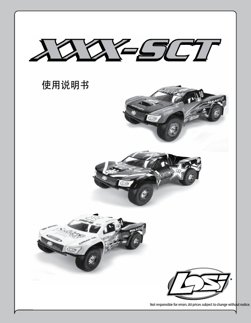
使用说明书Not responsible for errors. All prices subject to change without notice.警告:您在操作本产品前请先阅读全部说明书内容,了解产品的特性。
不正确的操作将导致产品损坏、 个人财产损失以及严重受伤。
这是精密的模型产品而不是玩具。
必须要谨慎、有常识、有基本机械操作能力。
未能以安全和负责任的态度操作本产品,会导致受伤、财产损失或产品损坏。
没有成人直接监督,儿童不宜使用本产品。
未经Horizon允许的情况下,请勿尝试拆解或使用不兼容零件改装本产品。
说明书包含安全事项、操作和保养的说明。
为了正确地操作并避免损坏与受伤,组装、安装 或使用前,请务必阅读及遵循使用手册的说明和警告。
简介 ................................................................................................. ..........3在线注册您的 Losi产品 .......................................................................................... 3准备工作 ................................................................................................. ...... 3安全注意事项与指导.............................................................................................3快速开始 ................................................................................................. ......3峰值检测充电器 ................................................................................................ .4附属工具和需要的设备 ...........................................................................................4XXX-SCT电子系统概览 ........................................................................................... 4MSC-12L Fwd/Rev ESC(电子调速器) ............................................................................ 5安装发射机电池 ................................................................................................. 5安装动力电池 ................................................................................................. ..6Losi LSR-3000遥控系统 .......................................................................................... 6驾驶XXX-SCT的注意事项.. (7)目录故障排除指南................................................................................................. (8)RC遥控车技术................................................................................................. ..9零部件列表 ................................................................................................. (10)升级零件列表 (11)保修与退货 ................................................................................................. (12)联系信息 ................................................................................................. .. (13)FCC声明................................................................................................. (13)Compliance Information for the European Union (13)传动系统分解图................................................................................................ 车体后部分解图................................................................................................车体前部分解图 ................................................................................................底盘分解图 ................................................................................................. ...设定表 ................................................................................................. .....注意所有使用说明、保修条例和其他附属文件由Horizon酌情自行变更。
宝元说明接510I线

z CAD/CAM z 網路功能
1.2 LNC-M510i 控制器
LNC-M510i 控制器採用標準的工業電腦為基礎,適用於一般工具機、產業機器與自動化機具,此構裝具有良好 的維護性,高性能的運動控制功能與多點數 I/O 點支援,可廣泛應用於各種工業應用,加上 PC 的開放式系統, 模組化的設計,使系統性能升級容易,維護更方便。 主要規格如下: 1. 傳輸介面支援 Ethernet、DNC 2. 提供 3 軸同動 Pulse / Vcmd 位置迴路控制(Vcmd 為選配) 3. 提供主軸介面 Pulse / Vcmd 介面 4. 提供一組編碼器輸入可給 MPG 使用 5. I/O 介面支援到 128 Input / 128 Output 點
1.1 一般規格及選配規格.......................................................................................................................1 1.2 LNC-M510i 控制器 ........................................................................................................................1 1.3 硬體規格.........................................................................................................................................2 1.4 LNC-M510i 電源需求 .....................................................................................................................2 1.5 軟體規格.........................................................................................................................................3
Hyperion EOS 0615i DUO3 充电器中文说明书

Hyperion EOS0615i DUO3 充电器用户指南3.1 固件版本,请访问http://media.hyperion.hk/dn/eos获得最新的说明和固件以及软件的信息。
产品包含USB接线,只是途中没有给出警告:EOS 0615i DUO3 是一款经过精心设计的具有众多安全保护特性的充电器,例如反极性接电保护、输入电压错误警告, 聚合锂电池片数错误时警告等安全特性。
但是,用户有必要保证此充电器设定正确并且工作在合适的环境中。
•充电器的电池种类的设定,必须与当前充电的电池相符合•锂电池的平衡充接口必须和充电器的多功能平衡充适配接口相匹配•同步模式(SYNC MODE) 充电时,充电器应该工作在与输出相当的放电条件下(后文有详细说明)•确认您的电池可以在你设置的充电速率下充电•充电时需要有人看护•充电应该在防火的环境下进行,例如在水泥地面或者砖地上•不要在容易着火的材料附近充电•不要把电池放在模型中进行充电•建议您可以在户外的可行的场所充电•充电器的输出线使用高质量的4mm金头。
见“安装”•适当的绝缘措施和经常检查连接可以防止短路发生。
由输出短路所造成的设备破坏,不在保修范围之内。
•供电后,充电器的盒子不可以接触直流/交流的供电•不要跌落充电器,或者对充电器震动/撞击,也不要让充电器受到潮气,湿气或者液体的影响•不要尝试给如下情况的电池充电:不同种类电池片构成的电池,新旧电池片混合构成的电池,和EOS 0615i DUO3所不支持充电的电池•不要尝试给“非充电电池”充电•不要拆开充电器的盒子,否则将不予保修•充电器应放在儿童或者宠物无法触及的地方•不要尝试用两个充电口同时充同一块电池。
(例如,10S的电池)否则,会破坏充电器,电池,这种情况将不予保修。
DUO3 充电器设计为最大可以充6S的电池. 对于比6S片数还多的电池, DUO3 充电器支持同步模式(SYNC MODE) 为分开的两部分进行平衡充电,这两部分充电后并联,就可以达到多片数电池充电的效果。
让iPhone快速回血七款热门PD充电器横向评测

让iPhone快速回血七款热门PD充电器横向评测作者:来源:《微型计算机》2019年第10期对于数码发烧友而言,左手Switch、右手拿着新iPhone,背包里装着轻薄本,应该是一种生活常态了。
随着数据和充电接口的规范化,越来越多的随身数码产品开始支持USB PD协议。
特别是当Apple放开了Type-C转Lightning线的认证授权,第一批获得授权的第三方厂家已陆续推出相关产品,打破了价格壁垒,PD充电器得到了快速普及。
从28元的绿联PD充电器,到售价243元的Apple USB-C充电器,从18W功率到65W功率,PD充电器呈现出价格跨度大、品类多、支持协议不统一的特点,对普通消费者而言选择也就更加困难。
所以我们选择了7款市面上热门的PD充电器产品,通过CharqerLAB的POWER-Z FL001S和KM001C工具進行协议兼容性、即时输出功率和完整充电曲线测试,使用FLIR i7红外热像仪测量快速充电时充电器和手机机身的温度表现,以直接的结果为用户提供入手参考。
Apple USB-C充电器2018年10月底,苹果推出了18WUSB PD充电器,并将它标配在新的iPadPro上。
充电器的外壳采用了白色PC材质,经过高光处理,插脚不可折叠。
对比iPhone配备的“五伏一安”充电器,AppleUSB C充电器的体积会更大一些,便携性上稍有不如。
兼容性方面,我们发现它仅支持USBPD快充协议,而Apple 2.4A、QC2.0、QC3.0、FCP、SCP等快充协议均不支持。
同时,仅有的Type-C接口只支持5v/3A和9v/2A两种输出,最高功率18W。
可以说,Apple USB-C充电器完全是为Apple旗下的新产品所设计。
测试环节中,我们先后使用AppleUSB-C充电器为iPhone XS Max和MacBook Pro进行充电。
从iPhone XSMax的完整充电曲线图可以看到,AppleUSB-C充电器的输出电压十分稳定,前期快速充电中始终维持在9V左右,涓流充电环节则降至5.2V左右。
5v1a方案
5v1a方案随着社会的不断发展和科技的进步,电子产品已经成为人们日常生活中必不可少的一部分。
而电子产品的使用过程中,充电困扰着许多人。
尤其是当我们需要给多个设备同时充电时,充电线杂乱、插座不够用等问题成为了我们面临的挑战。
为了解决这个问题,我们提出了一种5v1a方案。
该方案的核心是使用一种名为“5v1a多功能充电器”的设备,它能够同时给五个设备提供稳定的5V 1A电压。
以下是关于该方案的详细说明。
一、方案的设计理念该方案旨在提供一个方便、高效、安全的充电解决方案,以满足人们同时给多个设备充电的需求。
通过使用一台5v1a多功能充电器,用户可以同时给手机、平板电脑、蓝牙耳机等设备充电,彻底解决了充电线杂乱、插座不够用的问题。
二、产品特点1. 多口设计:该多功能充电器设计有五个USB接口,可以同时给五个设备充电。
这样,用户就不再需要准备多个充电器,大大方便了出行和日常使用。
2. 安全稳定:该充电器具有过流保护、过载保护和短路保护功能,可确保在充电时设备不受损坏。
同时,它还采用了高效的充电芯片,能够提供稳定的5V 1A输出电压,保证设备安全充电。
3. 精致外观:多功能充电器采用了简约时尚的外观设计,配色简单大方。
紧凑的尺寸使其易于携带,方便用户在办公室、家庭、旅行等场合使用。
4. 快速充电:该充电器还支持快速充电技术,能够根据设备需求智能调整输出电流,提供高效充电体验。
三、使用说明使用该方案很简单:1. 将多功能充电器插入电源插座,并确保充电器正常工作。
2. 将需要充电的设备通过USB线连接到充电器的USB口上。
3. 开始充电。
需要注意的是,为了保证充电速度和安全性,建议使用原装的USB 充电线。
四、市场前景和竞争优势5v1a多功能充电器方案有着广阔的市场前景和巨大的竞争优势。
首先,如今人们对电子产品的需求量越来越大,5v1a多功能充电器方案可以满足用户同时给多个设备充电的需求,极大地解决了用户的痛点。
FM01BTS FM01BTD 充电器驱动IC说明书

FM01BTS/FM01BTD文件编号:S&CIC1270)充电器驱动IC功能描述FM01BTS/FM01BTD (文件编号:S&CIC1270) 充电器驱动IC电气参数VDD=5V , Vout=5V Ta=25℃, 除非另有说明。
参数 符号 测试条件 最小值 典型值 最大值单位开启电压 VDDon VDD 上升从0开始 5 5.8 -- V 关闭电压 VDDoff 开关打开之后VDD 下降2.5 2.8 -- V 工作电流 IDD 正常工作 -- 1 3 mA 启动电流 IDDst开关打开之前-- 30 50 uA效率 η -- -- 78 -- %前沿消隐时间 -- -- -- 600 -- ns 过温关断点-- -- -- 145 --℃性能介绍参数归纳项目规范 测试输入特性AC 输入电压范围AC 180V~264V AC 180V~264V待机功耗<0.3W 0.22W输出特性DC 输出电压 -- DC 5V~5.5V输出电流典型值(可调)-- 500mA~1A开启延迟时间<1S 0.5S保护开路保护 -- Pass短路保护-- PassFM01BTS/FM01BTDFM01BTS/FM01BTDFM01BTS/FM01BTD(文件编号:S&CIC1270)充电器驱动ICBOM表成品物料:序号名称规格用量备注1 PCB 30×53mm 1.2mm HB纸板 1 --R112 碳膜电阻 1.5M±5% 1/4WR213 碳膜电阻100K±5% 1/4WR3a、R3b24 碳膜电阻 4.7R±1% 1/4WR65 碳膜电阻510R±5% 1/4W1FR6 碳膜电阻10R±5% 1/2W1C17 电解电容 4.7uF/450V±20% 8×12 1C28 插件电容 4.7NF/250V CAP-41C39 电解电容10uF/50V±20% 4×7 110 电解电容10V 1000uF 5×11 1 C4D111 二极管FR107 DO-411D3112 二极管FR107 DO-41D7113 二极管SS34 SMA14 发光二极管∮3mm白发红普亮、短脚 1 LED115 变压器 EE13W卧式(FM01BTS) 1 T116 AC电子线Φ1.5×40mm 黑 2 AC1、AC2变压器规格结构图:骨架类型PIN数目针距排距备注EE13卧式、TDK PC40 4+4 2.5mm 12.1mm 卧式FM01BTS/FM01BTDFM01BTS/FM01BTD(文件编号:S&CIC1270)充电器驱动IC 应用板重要波形:VIN-AC=265V,Iout=1A时,三极管C脚波形如下:(VCE=540V,F=41KHZ)VIN-AC=220V,Iout=1A时,CS脚波形如下:(VCS=800mV,F=43KHZ)FM01BTS/FM01BTD(文件编号:S&CIC1270)充电器驱动ICVIN-AC=220V,Iout=0时,VCC(CH1)、CS(CH2)、C(CH4)波形如下:(VCC=5.2V,VCS=800mA,F=720HZ&2KHZ)VIN-AC=220V,Iout=1A时,VCC(CH1)、CS(CH2)、C(CH4)波形如下:(VCC=5.6V,VCS=800mA,F=41KHZ)FM01BTS/FM01BTD(文件编号:S&CIC1270)充电器驱动IC成品测试技术规范:1、适用范围:以下成品测试技术规范适用于本公司设计生产的FM01BTS、FM01BTD手机直充充电器。
顾德电子 灯光控制台 说明书

1.4. 清除全部数据 ..........................................................................................................................................................6 2. 灯光设备单元的配接 ..........................................................................................................................................................7 2.1. 灯光设备的地址匹配 ..............................................................................................................................................7 2.2. 配接调光光路 ..........................................................................................................................................................7 2.3. 配接电脑灯 ..............................................................................................................................................................8 2.4. 电脑灯通道属性设置 ..............................................................................................................................................9 2.5. 查看灯光设备的配接 ............................................................................................................................................10 3. 手动控制光路与电脑灯 .................................................................................................................................................... 11 3.1. 观察控制台的输出 ................................................................................................................................................ 11 3.2. 现场表演模式 ........................................................................................................................................................ 11 3.3. 手动控制光路 ........................................................................................................................................................12 3.4. 手动控制电脑灯 ....................................................................................................................................................12 3.5. 运行宏 Macro ........................................................................................................................................................12 3.6. 改变电脑灯的属性值 ............................................................................................................................................13 3.7. 电脑灯的排列与扇形模式 ....................................................................................................................................13 3.8. 手动控制的清除 ....................................................................................................................................................13 3.9. 灯光设备编组 ........................................................................................................................................................14 3.10. 举例 Examples .......................................................................................................................................................14
Injoinic IP6520 18W USB Type-C 快充转换器说明书
18W PD输出,集成多种快充输出协议(DCP/QC2.0/QC3.0/FCP/HSCP/AFC/MTK PE/ PD3.0/PPS)的SOC1 特性•同步开关降压转换器✧内置功率MOS✧输入工作电压范围:7.1V到32V✧输出电压范围:3V到12V,根据快充协议自动调整✧PD输出功率:最大18W(5V/3A,9V/2A,12V/1.5A)✧输出电压有线补功能,50mV/A✧VIN=24V,VOUT=5V/3A,板端转换效率为93.8%✧软启动功能•支持Type-C输出接口和USB PD协议✧PD3.0 USB-IF协会认证TID: 3277✧支持5V、9V、12V电压输出✧支持PD2.0/PD3.0(PPS)输出协议✧PPS支持3~11V,20mV/step电压输出•输出快充规格✧支持Type-C PD口输出✧支持BC1.2和Apple协议✧支持QC2.0、QC3.0快充协议✧支持华为快充协议FCP和高压SCP✧支持三星快充协议AFC(MAX 12V)✧支持MTK PE+1.1和MTK PE+2.0•多重保护、高可靠性✧输入过压、输入欠压、输出短路、输出过流保护✧整机过温保护✧DP/DM/CC过压保护✧CC PIN耐压30V✧ESD 4KV,直流耐压40V2 应用•车载充电器•快充适配器•智能排插3 简介IP6520是一款集成同步开关的降压转换器、支持多种输出快充协议、支持Type-C输出和USBPD2.0/PD3.0(PPS)协议,为车载充电器、快充适配器、智能排插提供完整的解决方案。
IP6520内置功率MOS,输入电压范围是7.1V到32V,输出电压范围是3V到12V,能提供最大18W 的输出功率,能够根据识别到的快充协议自动调整输出电压和电流,典型输出电压和电流有:5V/3A,9V/2A,12V/1.5A。
IP6520的PD输出具有CV/CC特性,当输出电流小于设定值,输出CV模式,输出电压恒定;当输出电流大于设定值,输出CC模式,输出电压降低。
基于单片机智能充电器设计
[键入文字]智能电瓶充电器的设计摘要本文着重介绍了慢脉冲智能充电方法的应用,同时介绍了慢脉冲快速充电方法的基本原理,利用慢脉冲快速充电方法提高充电速度。
在充电过程中用单片机控制,实现过冲保护。
该系统具有自动化程度高、运行费用低、工作可靠等优点。
关键词:;智能电瓶充电器;89S51单片机目录第一章引言 (1)1.1 本课题的研究背景、发展及意义 (2)1.2 本课题的基本内容 (1)第二章基本理论介绍 (2)2.1 铅蓄电池充电理论基础 (2)2.2 充电方法的研究 (3)2.3 脉冲快速充电法的理论基础 (7)2.4 充电方法设计 (8)第三章设计方案论证 (9)3.1 控制方式 (9)3.2 方案设计 (9)第四章硬件电路设计 (10)4.1 充电器主电路设计 (10)4.2 控制电路的设计 (13)4.3 整体电路设计 (16)第五章软件设计 (17)5.1 温度检测中断程序 (17)5.2 电压检测子程序............................. 错误!未定义书签。
5.3 充电脉冲控制子程序......................... 错误!未定义书签。
5.4 单片机主程序 (17)第六章设计总结 (25)第七章参考文献 (26)第一章引言1.引言一、电瓶的定义电瓶,也叫蓄电池,蓄电池是电池的一种,它的工作原理就是把化学能转化为电能。
通常,人们所说的电瓶是指铅酸蓄电池。
即一种主要由铅及其氧化物制成,电解液是硫酸溶液的蓄电池。
二、常用的蓄电池分类及特点1)普通蓄电池;普通蓄电池的极板是由铅和铅的氧化物构成,电解液是硫酸的水溶液。
它的主要优点是电压稳定、价格便宜;缺点是比能低(即每公斤蓄电池存储的电能)、使用寿命短和日常维护频繁。
2)干荷蓄电池:它的全称是干式荷电铅酸蓄电池,它的主要特点是负极板有较高的储电能力,在完全干燥状态下,能在两年内保存所得到的电量,使用时,只需加入电解液,等过20—30分钟就可使用。
上汽大众新途观L使用维护说明书

本说明书适用于下列表中各种型号的上汽大众新途观L多用途乘用车。
用户在使用本公司产品以前,必须认真研读产品使用维护说明书,任何不当的使用、保养和修理都可能导致车辆的损坏及影响质量担保服务。
因此,在使用产品前请认真阅读本使用维护说明书,并对照表中的型号确认您的车型。
上汽新途观L多用途乘用车SVW64712AT DJS七挡自动变速器上汽新途观L多用途乘用车SVW64712BV DPL七挡自动变速器上汽新途观L多用途乘用车SVW64712CV DPL七挡自动变速器上汽新途观L多用途乘用车SVW64712DV DPL七挡自动变速器上汽新途观L多用途乘用车SVW64712EV DKX七挡自动变速器本使用维护说明书描述了该车型车辆在当前范围的配置、功能及操作的一般通用信息,但用户车辆的实际配置和功能等信息以具体交付时的为准。
本公司将持续对各种车型进行改进,各车型在外形、配置、功能和结构设计等方面也可能随时会发生变化,故本公司有权在法律法规允许的范围内对本说明书有关版本进行更改、补充,若用户对此有疑义请及时拨打上汽大众客户服务热线400-820-1111予以咨询。
未经本公司书面同意,不得复制、翻译或摘录本使用维护说明书。
上汽大众汽车有限公司依法保留对本说明书有关版本进行更改、补充等的一切权利。
中国印刷。
上汽大众汽车有限公司公司地址:中国上海安亭于田路邮政编码:201805企业标准号:Q/JQAB 354-2021Q/JQAB 355-2021致尊敬的用户尊敬的用户:感谢您对上汽大众的信任与厚爱!在您选择了上汽大众产品的同时,您已经启动了全新的汽车生活之旅。
在整个旅行过程中,上汽大众和旗下1000余家大众品牌特许销售商/特约维修站都将始终陪伴您左右。
衷心希望您的每一天行车生活,都因有上汽大众的同行而更精彩!如果您对车辆使用有任何疑问,上汽大众经销商随时随地为您提供帮助,我们的上汽大众客户服务中心全国统一寻呼400-820-1111也将是您的坚强后盾。
华硕 ROG Zephyrus G14 GA401 笔记本电脑 用户手册说明书

目录版权与商标声明 ........................................................................................................................1-4修订 ...........................................................................................................................................1-4FCC-B 频道干扰声明...............................................................................................................1-5FCC 规定 ..................................................................................................................................1-5CE 规定.....................................................................................................................................1-5电池规范 ...................................................................................................................................1-6WEEE 声明...............................................................................................................................1-6化学物质法规 .........................................................................................................................................1-6升级和保修 ...............................................................................................................................1-7购买备件 ...................................................................................................................................1-7安全指南....................................................................................................................................1-8产品中有害物质的名称及含量................................................................................................1-10MSI 特殊功能 .........................................................................................................................1-11简介 ...............................................................................................2-1打开包装 ...................................................................................................................................2-2产品检视....................................................................................................................................2-3顶盖开启检视图...................................................................................................................2-3前端检视图 ..........................................................................................................................2-6右端检视图 ..........................................................................................................................2-7左端检视图 ..........................................................................................................................2-8后端检视图 ........................................................................................................................2-10底部检视图 ........................................................................................................................2-11如何使用键盘..........................................................................................................................2-13 Windows 键.......................................................................................................................2-13快速启动按键 ....................................................................................................................2-14开启或关闭触摸板.............................................................................................................2-15进入睡眠模式 ....................................................................................................................2-15切换显示器 ........................................................................................................................2-15使用多个监视器 ................................................................................................................2-15调整显示器的亮度 ............................................................................................................2-16调整扬声器的音量.............................................................................................................2-16调整键盘背光 LED 灯的亮度(选择性配置) ..................................................................2-16应用程序:True Color (选择性配置)...............................................................................2-17产品规格..................................................................................................................................2-18使用者手册如何使用入门 .................................................................................3-1开始使用笔记本电脑 ................................................................................................................3-2如何舒适地使用笔记本电脑.....................................................................................................3-3如何使用电源供应器 ...............................................................................................................3-4电源适配器.........................................................................................................................3-4电池.....................................................................................................................................3-4如何在 Windows 10 下设置一个电源计划设定 .....................................................................3-6选择或自定义电源计划 ......................................................................................................3-6创建自己的电源计划 ..........................................................................................................3-9如何使用触摸板 .....................................................................................................................3-11了解一般硬盘和固态硬盘.......................................................................................................3-12了解 M.2 固态硬盘插槽..........................................................................................................3-12如何连接 Internet ...................................................................................................................3-13无线网络 ............................................................................................................................3-13有线网络 ............................................................................................................................3-15如何设置蓝牙连接.................................................................................................................3-20开启蓝牙连接 ...................................................................................................................3-20如何连接外部装置.................................................................................................................3-23视频:如何使用 RAID 功能...................................................................................................3-24如何在 BIOS 中选择 Boot Mode..........................................................................................3-25视频:如何在 MSI 笔记本电脑上恢复 Windows 10 操作系统............................................3-26视频:如何使用 MSI 一键安装 .............................................................................................3-27版权与商标声明Copyright© 微星科技股份有限公司所有。
Omni Ultimate 产品说明书
POWER YOUR NEXT ADVENTURE For more information visit our support page at www.omnicharge.coBEFORE USING Calibrate the battery1. Fully discharge Omnicharge until the screen turns off. Press the Power Button and you should see an empty battery icon on the screen.It's easy to do. Follow these steps:To make sure the battery reading is correct, please calibrate the Omnicharge battery when you first receive the product and periodically in the future.2. Fully charge your Omnicharge to 100% to finish the calibration........................................................................................................................................................................................................................................................................................................................................................................................................................................................................................................................................................................................................................................................................................CACPORTS AND BUTTONS1. Power and Menu Button2. AC Outlet Button/Move Up3. DC Outlet Button/ Move Down4. AC Outlet5. DC Input Port6. USB-A Ports7. USB-C Input / Output Port8. DC Output Port.......................................................................................................................................................................................................................................................................................................................................................................................................................................................... (31)245678BUTTON FUNCTIONSSCREEN OLED screen with real time metricsMAIN CONTROLS MENU CONTROLS• Long press to power on • Quick press to turn screen display on/off• On/Off AC outlet • DC out settings • Double press to enter the menu • Quick press to select• Move Up • Move Down (6)543210.00 AC DCC 1. Status Icons 2. Total Input Wattage 3. Total Output Wattage from the Battery 4. Battery Temperature 5. USB-C/Barrel DC Output Voltage 6. Battery Percentage RemainingWhile your Omni Ultimate is powered on press and hold the AC button to enter Lock Mode. Lock mode locks the device and turns off all lights while still outputting power from the ports. Press and hold the AC button to deactivate Lock Mode.LOCK MODE• Long Press to enter lock modeSCREEN ICONSADJUSTABLE DC OUTPUT Adjustable 5V-60V DC output is activated.AC OUTPUT AC outlet is B-C OUTPUT 60W USB-C output is activated.USB OUTPUT USB ports are turned on.CHARGING INPUT Your Omnicharge is being charged.OPTIMAL CHARGING Charging at maximum power. SOLAR CHARGING Charging from solar power..........................................................................................................................................................................................................................................................................................................................................................................................................................................................................................................................................................................................................................................................................................................................................................................................................................................................................................................................................................................................................................LOW TEMPERATURE PROTECTION Battery's temperature is too low and the charging circuit is shut off.OVERPOWER PROTECTION Device is drawing too much power. Omnicharge will limit or cut off the output power.OVERHEATING PROTECTION Battery temperature is too high. Omnicharge will limit or cut off its input and output power.OVERVOLTAGE PROTECTION Barrel input voltage exceeds the 32V limit. Input charging circuit is shut off.LOW POWER PROTECTION (ONL Y DURING PASS-THROUGH)Occurs when outgoing power is higher than incoming power and battery is empty. Omnicharge will cut off the outgoing power until a sufficient battery level has been reached.................................................................................................................................................................................................................................................................................................................................................................................................................................................................................................................................................................................................................................................................................................................2. USB Choose whether your USB-A ports are on or off when you turn on your Omnicharge. The default setting is on.3. SCREEN OFF TIMERSet the screen auto shut-off time here. The default setting is 5 min.1. DC OUTTurn on DC output and set the voltage and amperage...........................................................................................................................................................................................................................................................................................................................................................................................................................................................25.0V = 7.5A2.DEFAULT ON3.While the screen is on double press the power button to enter the menuWhen in the menu, navigate up and down using the buttons on the right of the screen. Use the power button to enter the selected menu item.DC OUT USBSCREEN OFF6. TEMPERATURE Choose whether your temperature is displayed in celcius or fahrenheit7. BUTTON LIGHT Choose whether the button lights are on or off. The default setting is on.8. ABOUTFind the model name, capacity, firmware version, and serial number information here.5. AUTO SHUT DOWNSet the power auto shut-off time here. The default setting is 5 min..............................................................................................................................................................................................................................DEFAULT ON6.5.7.8.AUTO SHUT DOWN TEMPERATUREBUTTON LIGHTNEVER˚CABOUTPower any deviceLaptop TV Drone DSLR Projector And more Max output power: 120W US/JP EU1. Quick press AC Output Button to turn the AC outlet on/off2. The AC icon should appear on the screen AC 120V/230V AC output.............................................................................................................................................................................................................................Note: Due to the high power pure sinewave AC output, you might experience some electrical interference on the USB-A and USB-C ports when simultaneously outputting from the AC outlet.5V - 60V with 0.1V/A Accuracy, up to 8A (150W max)Set the voltage and amperage through the menu (You can also click the DC Output Button to jump to Step 2)DC OUT .......................................................................................................................................................................................................................................................................................................................................................................................................................................................................................................................................................................................................................................................................................DC icon will appear on the screen Adjustable DC outputPower your device through the DC port (MR30)To make the Omni Ultimate compatible with our older 5.5 x 2.1mm barrel cables, we have included an DC output barrel adapter.Step 2Step 2Step 2Omnicharge keeps 4 voltage presets. You can press and hold the power button while selecting a preset to customize the voltage and amperage.USB DC25.0V = 7.5A Warning: Before using DC Output make sure you know the correct voltage for your laptop. Using the wrong voltage can damage your device.The DC output feature can directly charge your laptop without needing your laptop charger. Note: For more information visit our support page at www.omnicharge.co/supportUSB-A PORTS1. Choose whether the USB output is on or off when you turn on your Omnicharge DEFAULT ON .............................................................................................................................................................................................................................5V/3A, 9V/2A, 12V/1.5A QC3.0 compatible 5V, 9V, 12V, 15V, 20V, up to 3A 60W maxUSB-C INPUT/OUTPUT PORT .............................................................................................................................................................................................................................Charging from the Wall Use the included AC wall charger, or other power adapters like your laptop charger to recharge your Omnicharge.Note: Make sure the output voltage of your adapter falls within 5V - 32V range. The Omni Ultimate can accept 5.5 x 2.5 mm barrel plugs.THE OMNICHARGE CAN BE RECHARGED IN A VARIETY OF WAYS DC Input 5-32V, 4.5A max, 90W max USB-C Input 5V/3A, 9V/3A, 12V/3A, 15V/3A, 20V/3A, 60W max USB USB*********************. ..................................................................................................................................................................................................................................................................................................................................................................................................................................................................................................................................。
E150EV系列维修手册(上篇)1114
E150EV 2013 目录
2.11 冷却系统 ........................ቤተ መጻሕፍቲ ባይዱ.............................................................................................. 77 2.12 其它部分 ........................................................................................................................ 80
5 组合仪表 ....................................... 17
5.1 概述 ................................................................................................................................. 17 5.2 接口定义 ......................................................................................................................... 18 5.3 拆装 ................................................................................................................................. 19 5.4 组合仪表上的指示灯 ..................................................................................................... 21 5.5 保养周期显示:复位 ..................................................................................................... 22
ppbRAE 3000 中文说明书

Rev. A 2007 年 11 月 P/N 059-4021-C00
目录
使用前须知 ......................................................................................................................................1 注 意 ................................................................................................................................................1 特别提示 ..........................................................................................................................................1 警 告 ................................................................................................................................................1 标准配置 ..........................................................................................................................................2 产品概述 ..........................................................................................................................................2 主要部件 ..........................................................................................................................................2 技术指标 ..........................................................................................................................................3 检测范围及分辨率 ..........................................................................................................................3 电池充电 ..........................................................................................................................................4
萤石电源国标5V1A规格要求REV1.4

萤石电源国标5V1A规格要求-----Rev1.4提醒:送样之前要先发规格书+EMC测试报告+可靠性测试报告等文件给我司确认,确认无误后再送样一、 电气规格1.1、输入特性规格参数最小值Nominal 最大值输入电压90Vac 100-240Vac 264Vac输入频率47Hz 50-60Hz 63Hz功率因数无要求能效要求满足能效Ⅵ级1.2、输出特性输出电压(V)输出电流(A) 峰值电流(A)负载调整率电压调整率纹波/噪声(mV)Min.(A) Max(A)+5V(+5%,-0%) 0 1 1.2 ±5%±5%<50 备注:1.3、保护功能保护类型是否要求保护特性说明短路保护(SCP)是自恢复过流保护(OCP)是自恢复过压保护(OVP)是过温保护(OTP)否过功率保护(OPP)其他保护功能1.4、其他要求二、 环境特性工作温度范围-25℃~40℃储存温度范围-40 to 85℃相对湿度20% ~85%振动测试要求根据产品要求海拔要求满足新3C标准5000米要求注意:在60℃环境中,额定输入电压范围内,能满载正常工作168小时。
三、 法规要求3.1、安规认证认证名称是否要求认证标准CCC(国内)是GB4943其他海外认证要求认证名称是否要求备注3.2、EMC要求项目标准指标EmissionsEMI辐射EN55022 ClassB,6dB裕量EMI传导EN55022 ClassB ,6dB裕量Immunity浪涌抗扰度Surge IEC61000-4-5 3级,判据A,差模1.5KV,共模3kv.电快速脉冲群EFT IEC61000-4-4 3级,判据A,2KV静电ESD EN61000-4-2 接触6kv,空气8kv,判据A其他备注:1判据A,性能正常、不掉电不重启、状态正常2 要求输出端负极不接大地的情况下,辐射、传导都能通过3 浪涌测试时,共模测试地连接端为输出地四、 机械特性装配方式□板上型,□内置式,■插墙式,□桌面式 ,□其他外观尺寸(L*W*H)mm³见附件1参考,形状不变,尺寸可以变小。
网达通 使用、保修手册
1
欢迎使用:
网达通使用 Microsoft® Windows Mobile™ Version 6.1 操作系统, 是全新一代智能移动互联网终端。网达通 拥有时尚精致的外观设计、极佳的触摸操控系统和超强的兼容扩展功能,给您带来无限惊喜,并让您繁忙的商 务生活由此不同凡响。 销售包装中所示图文资料仅供参考。 技术规格的变化恕不另行通知。原厂配件供应,请向网达物流科技有限公司查询,客服电话:400-800-5656。 本手册之内容本公司享有修改、解释之权利,且不另行通知。用户可登录 /查阅 :
在提示不能使用无线通讯设备的场所,如医院、飞机机舱内、加油站以及其它应避免无线干扰的场所,请 您关闭本设备! 插入 UIM 卡时请确保外接电源已经断开,且 UIM 卡放置到位。 首次充电请充满 8 小时。在充电过程中,请不要将电池从手机中取出,以防损伤设备。充电时请安全操 作。 本机型不具防水功能,请您注意防水,保持手机的干燥。 人为损坏的或非经指定(授权)进行维修后造成设备损坏的,不享受设备保修的权利。 请使用由本公司制定的附件和认可的第三方软件,否则如果设备出现问题,本公司将不承担任何责任。 请使用屏幕保护贴,注意保护好手机屏幕,防止磨损或挤伤。此类损伤均被认为是人为损坏。 请及时备份数据! 本公司不承担因产品故障导致信息丢失而造成的一切直接或间接损失。 尤其在电池更换 前更加需要备份数据。 本设备包含有原装锂电池。如果电池处理不当,将会有着火和燃烧的危险。不要分解、挤压、刺穿电池, 不要短路电池外部的接头,更不要将其投入火中或者水中。不要试图打开或者维修该电池,只能使用产品 制定的电池进行更换。请正确处理电池,不要随意丢弃。 请妥善保管好您的手机,应避免让儿童随意摆弄、玩耍、拆解,避免儿童进行充电操作,以防止损坏设备 或出现其它意外,我公司不承担因此而造成的一切直接或接间损失。 由于软件版本更新而造成界面和功能变更,恕不另行通知。 本手册截图可能与实际设备显示有差异,请以实际设备显示为准。 有关图片仅作为示意和说明使用,您所购买的具体产品的颜色和外观,请以实物为准。 Push Mail 的收发将产生运营商流量费用,在无需使用时请及时断开。 本机部分预装软件 windows mobile 为测试版本,部分音乐、视频或有版权,请及时购买正版软件和版权 进行使用。
usb c 5v1a防火要求

一、USB C 5V1A防火要求的重要性USB C 5V1A是一种常见的充电电源规格,广泛应用于移动设备、数码产品等领域。
然而,由于电子产品的充电过程中存在着一定的安全隐患,因此对USB C 5V1A的防火要求显得尤为重要。
实施有效的防火要求可以有效减少充电过程中的安全隐患,降低使用过程中发生火灾的可能性,对保障用户的人身财产安全至关重要。
二、USB C 5V1A防火要求的相关标准和规定1.国际标准根据国际电工委员会(IEC)发布的相关标准,USB C 5V1A的防火要求包括但不限于以下几个方面:- 电气性能要求:对USB C 5V1A的输入电压、输出电压、电流波动等进行规范,确保其在充电过程中稳定可靠,不会发生电流过大或者电压波动过大的情况。
- 隔离保护要求:要求USB C 5V1A具有良好的漏电保护和过压保护功能,一旦出现漏电或者过压情况能够及时切断电源,避免发生火灾。
- 材料和结构要求:对USB C 5V1A的外壳材料、内部结构、散热设计等方面也有具体规定,确保产品在高温、高压等恶劣环境下也不会引发火灾。
2.国内标准在国内,国家质量监督检验检疫总局和我国国家标准化管理委员会发布了相关的防火要求标准,对USB C 5V1A的生产、进出口、销售等环节都进行了详细规定,要求厂家必须在生产过程中严格执行这些标准,确保产品的质量和安全性。
三、USB C 5V1A防火要求的意义和作用1. 保护用户安全USB C 5V1A的防火要求的实施可以有效保护用户的人身和财产安全,减少因充电过程中发生故障而引发的火灾事故,降低潜在的安全风险。
2. 促进产业健康发展严格执行防火要求可以促进USB C 5V1A产品的良性竞争,促进整个产业的健康发展。
只有通过提高产品质量和技术水平,提升市场知名度和竞争力,才能在市场竞争中立于不败之地。
3. 增强国家监管和管理力度防火要求标准的实施也是国家对行业的监管和对企业的管理的一种体现,有助于加强国家对电子产品行业的监管力度,提高产品和企业的合规性和透明度。
5v1a充电协议代码
5v1a充电协议代码摘要:1.充电协议简介2.5V1A充电协议的原理3.5V1A充电协议的优势4.5V1A充电协议的应用场景5.5V1A充电协议的实践案例6.充电协议的未来发展正文:随着科技的飞速发展,充电协议也在不断更新和完善。
5V1A充电协议作为一种常见的充电协议,广泛应用于各种电子设备中。
本文将从充电协议简介、原理、优势、应用场景、实践案例和未来发展等方面进行详细介绍。
一、充电协议简介5V1A充电协议,即输出电压为5V,输出电流为1A的充电协议。
它是由国际电工委员会(IEC)制定的一种通用充电标准,适用于智能手机、平板电脑、笔记本等电子设备。
二、5V1A充电协议的原理5V1A充电协议的原理主要包括以下几个方面:1.充电设备:充电器、数据线和充电接口。
2.充电控制器:控制充电过程,确保充电设备安全。
3.充电协议芯片:识别充电设备和充电协议,实现充电数据传输。
4.电池:储存电能,为充电设备提供电源。
三、5V1A充电协议的优势1.兼容性:5V1A充电协议广泛应用于各种电子设备,充电器、数据线和充电接口通用。
2.安全性:充电协议具有过压、过流、短路等保护功能,确保充电过程安全。
3.高效性:充电速度适中,满足大部分充电需求。
四、5V1A充电协议的应用场景5V1A充电协议广泛应用于智能手机、平板电脑、笔记本、智能手表、耳机等电子设备的充电。
此外,一些电动工具、家居设备等也采用此充电协议。
五、5V1A充电协议的实践案例以智能手机为例,大部分手机充电器均采用5V1A充电协议。
如苹果iPhone、华为、小米等品牌,它们的充电器及数据线均支持5V1A充电协议。
六、充电协议的未来发展随着充电技术的发展,未来充电协议将更加高效、安全、智能。
例如,快速充电技术(如OPPO的VOOC、华为的SuperCharge)、无线充电技术(如Qi标准)以及充电协议的智能化(如通过AI算法优化充电过程)等。
总之,5V1A充电协议作为一种通用、安全、高效的充电标准,已在众多电子设备中得到广泛应用。
- 1、下载文档前请自行甄别文档内容的完整性,平台不提供额外的编辑、内容补充、找答案等附加服务。
- 2、"仅部分预览"的文档,不可在线预览部分如存在完整性等问题,可反馈申请退款(可完整预览的文档不适用该条件!)。
- 3、如文档侵犯您的权益,请联系客服反馈,我们会尽快为您处理(人工客服工作时间:9:00-18:30)。
2Ts Tape
8(F)
Triple Insulated Wire 0.50mmx1 9Ts –Secondary (Anti-Clockwise)
9(S)
NC
Core is connected to Pin-2
2(F) 1(S)
2UEW 0.14mmx1 13Ts– Bias (Clockwise) Evenly covered 2UEW 0.14mmx1 14Ts– Forward (Clockwise) Evenly covered
2. Schematic
CR1510
3
CR1510-10 for 5V1A Dialog Semiconductor Confidential
Jul 29, 2013
3. Circuit Board Photograph
Primary
Secondary
EM15
14mm
29mm
CR1510-10 Digital & Primary VMS Controller & BJT
OCP (A)
Average η(% )
90
1.10
77.13
115
1.12
78.33
230
1.09
77.39
264
1.08
76.44
*Note: Output voltage is measured at the end of PCB.
7 CR1510-10 for 5V1A Dialog Semiconductor Confidential Jul 29, 2013
Symbol
Min
Typ
Max
Units
Comment
VIN fLINE
90 47 50/60
264 63 0.1
VAC Hz W
2 Wire
Output Current
IOUT
1
A
Add 0.1uF Ceramic capacitor and 1uF E-cap at the end of connector and set oscilloscope at 20MHz bandwidth.
22 23 24
5
T1 EM-15, Horizontal Type PCB single Board, 94V0, FR-4 1mm L,N connecting line OD:0.3mm L=15mm
Jul 29, 2013
CR1510-10 for 5V1A Dialog Semiconductor Confidential
Free convection, sea level
POUT IOCP
5 1.2
W A
Auto-restart Measured at end of USB-Connector VIN = 115VAC and 230VAC (TAMB = 25 ℃).
68.2
%
CR1510-10 for 5V1A Dialog Semiconductor Confidential
POUT (W)
1.293 2.585 3.870 5.160 1.293 2.585 3.878 5.170 1.290 2.585 3.878 5.170 1.290 2.580 3.878 5.170
η (% )
77.30 78.12 77.15 75.93 77.58 78.84 78.75 78.16 75.35 77.28 78.29 78.66 74.22 76.13 77.36 78.04
Output Ripple Voltage
VRIPPLE
80
mVP_P
Total Output Power Continuous Output Power Over Current Protection Active Mode Efficiency (DOE Requirement) Environmental Conducted EMI Safety Ambient Temperature 2 TAMB Meets CISPR22B / EN55022B Designed to meet IEC60950, UL1950 Class II 0 35 Jul 29, 2013 °C
2UEW 0.14mmx1 45Ts– Primary (Clockwise)
2UEW 0.14mmx1 45Ts– Primary (Clockwise) 2UEW 0.14mmx1 45Ts– Primary (Clockwise)
6(S)Biblioteka FINISHED :1. 拔除pin3,pin4.并剪短pin7平bobbin面 2. Varnish the complete assembly
IOUT (A)
0 0.25 0.5 0.75 1 0 0.25 0.5 0.75 1 0 0.25 0.5 0.75 1 0 0.25 0.5 0.75 1
VRIPPLE (mVP-P)
18 34 46 62 72 18 32 46 58 71 20 44 42 52 68 18 44 42 54 64
Secondary Side component 330uF, 6.3V, E-Capacitor
V3L45, 3A45V, Schottky Diode, SMD,DO-221AC Vishay 3K±1%,SMD-0603 USB Connnecter (Horizontal tape)
Other component
7. Efficiency Measurement(Meet DoE)
DOE (Final) for Low Voltage Model (Pno=5W)
0.0834*ln(5)-0.0014*5+0.609=73.62 lots of Margin!
VIN (VAC) IOUT (mA) 250 500 750 1000 250 500 750 1000 PIN (W) 1.666 3.279 4.924 6.615 1.712 3.345 4.953 6.573 VOUT_PCB (V) 5.17 5.17 5.17 5.17 5.16 5.17 5.17 5.17 Measure at end of PCB POUT_PCB (W) 1.293 2.585 3.878 5.170 1.290 2.585 3.878 5.170 EFF_PCB (%) 77.58 78.84 78.75 78.16 75.35 77.28 78.29 78.66 AV-EFF_PCB (%) Measure at end of Cable 26AWG/1m, RCable=0.286Ω VOUT_Cable POUT_Cable EFF_Cable AV-EFF_Cable (V) (W) (%) (%) 5.10 1.27 76.51 5.03 2.51 76.65 75.62 4.96 3.72 75.48 4.88 4.88 73.83 5.09 1.27 74.31 5.03 2.51 75.14 74.70 4.96 3.72 75.04 4.88 4.88 74.30
EM15, the width of winding slot is 7mm
Jul 29, 2013
6
CR1510-10 for 5V1A Dialog Semiconductor Confidential
6. Regulation, Ripple and Efficiency Measurement
5. Transformer Design
SCHEMATIC
Instruction for start of first winding…
9 1 6
5
Primary 135Ts 9Ts
8
6 1
Bias 13Ts Note:
• Dot (●) denote electrical start.
9
Winding Start pin-6 & End pin-5 in “Clockwise” direction – looking from Pin 5/9 side of the Bobbin. PRI
Reference
U1 C13, C2 C4 C3 C7 C1 BD1 D1 D2 F1 L1 L2 R5 R3 R16 R11 C8 C18 D3 R4 USB
Description
CR1510-10, Off-line Digital PSR & PWM & VMS Controller & BJT, SOIC-8 4.7uF, 400V, Low-ESR E-Cap, Ф8mm X 10mm 470pF, 250V, X7R, SMD-0805 220pF, 100V, X7R, SMD-0805 2.2uF, 25V, X7R, SMD-0805 22pF, 25V, X7R, SMD-0603 ABS8,1A800V, Rectifier Bridge TSC SRGC10MH(FR107),1A800V, Fast Rectifier Diode,SOD-123 SRGC10DH(FR102),1A200V, Fast Rectifier Diode,SOD-123 10R/1W, Fuse resistance, Surface mounting 330uH, Color Ring Inductor, 0410 4.7uH, Chip Inductor, LQM21FN4R7M80, SMD-0805 220Ω ±5%, SMD-0805 2.52Ω ±1%, SMD-0805 15KΩ ±1%, SMD-0603 3K78 ±1%,SMD-0603 330uF, 6.3V,solid- Capacitor
