TXC晶体晶振 产品手册
晶振简介(OCXO恒温、
晶振简介(OCXO恒温、 MCXO数补、VCXO压控、VCTCXO、VCOCXO)各种晶振简介1. 普通晶振Packaged Crystal Oscillator(PXO):是⼀种没有采取温度补偿措施的晶体振荡器,在整个温度范围内,晶振的频率稳定度取决于其内部所⽤晶体的性能,频率稳定度在10-5量级,⼀般⽤于普通场所作为本振源或中间信号,是晶振中最廉价的产品。
2. 温补晶振Temperature Compensated Crystal Oscillator(TCXO):是在晶振内部采取了对晶体频率温度特性进⾏补偿,以达到在宽温温度范围内满⾜稳定度要求的晶体振荡器。
⼀般模拟式温补晶振采⽤热敏补偿⽹络。
补偿后频率稳定度在10-7~10-6量级,由于其良好的开机特性、优越的性能价格⽐及功耗低、体积⼩、环境适应性较强等多⽅⾯优点,因⽽获⾏了⼴泛应⽤。
3. 压控晶振Voltage Controlled Crystal Oscillator(VCXO):是⼀种可通过调整外加电压使晶振输出频率随之改变的晶体振荡器,主要⽤于锁相环路或频率微调。
压控晶振的频率控制范围及线性度主要取决于电路所⽤变容⼆极管及晶体参数两者的组合 4. 恒温晶振Oven Controlled Crystal Oscillator(OCXO):采⽤精密控温,使电路元件及晶体⼯作在晶体的零温度系数点的温度上。
中精度产品频率稳定度为10-7~10-8,⾼精度产品频率稳定度在10-9量级以上。
主要⽤作频率源或标准信号 5. 电压控制-温补晶体振荡器(VCTCXO)温度补偿晶体振荡器和电压控制晶体振荡器结合。
6. 电压控制-恒温晶体振荡器(VCOCXO)恒温晶体振荡器和电压控制晶体振荡器结合。
晶振的应⽤:晶体振荡器被⼴泛应⽤到军、民⽤通信电台,微波通信设备,程控电话交换机,⽆线电综合测试仪,BP机、移动电话发射台,⾼档频率计数器、GPS、卫星通信、遥控移动设备等。
SaRonix NTH NCH Series 晶体时钟振荡器规格书说明书
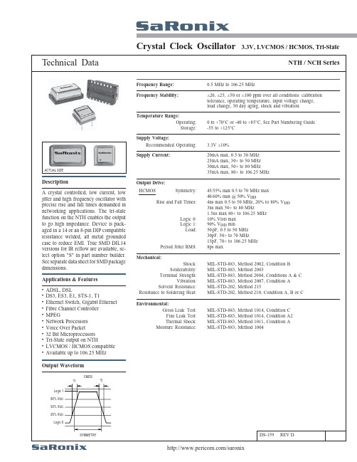
NTH / NCH SeriesSaRonixCrystal Clock OscillatorTechnical Data3.3V, LVCMOS / HCMOS, Tri-State/saronixDS-159 REV DSymmetry:Rise and Fall Times:Logic 0:Logic 1:Load:Period Jitter RMS:0.5 MHz to 106.25 MHzFrequency Stability:Frequency Range:±20, ±25, ±50 or ±100 ppm over all conditions: calibrationtolerance, operating temperature, input voltage change,load change, 30 day aging, shock and vibration.Temperature Range:Operating:Storage:0 to +70°C or -40 to +85°C, See Part Numbering Guide-55 to +125°CSupply Voltage:Recommended Operating: 3.3V ±10%Supply Current:20mA max, 0.5 to 30 MHz25mA max, 30+ to 50 MHz30mA max, 50+ to 80 MHz35mA max, 80+ to 106.25 MHzACTUAL SIZEDescriptionA crystal controlled, low current, lowjitter and high frequency oscillator withprecise rise and fall times demanded innetworking applications. The tri-statefunction on the NTH enables the outputto go high impedance. Device is pack-aged in a 14 or an 8-pin DIP compatibleresistance welded, all metal groundedcase to reduce EMI. True SMD DIL14versions for IR reflow are available, se-lect option "S" in part number builder.See separate data sheet for SMD packagedimensions.Output Drive:45/55% max 0.5 to 70 MHz max40/60% max @ 50% V DD4ns max 0.5 to 50 MHz, 20% to 80% V DD3ns max 50+ to 80 MHz1.5ns max 80+ to 106.25 MHz10% V DD max90% V DD min50 pF, 0.5 to 50 MHz30pF, 50+ to 70 MHz15pF, 70+ to 106.25 MHz8ps maxHCMOSMechanical:Shock:Solderability:Terminal Strength:Vibration:Solvent Resistance:Resistance to Soldering Heat:MIL-STD-883, Method 2002, Condition BMIL-STD-883, Method 2003MIL-STD-883, Method 2004, Conditions A & CMIL-STD-883, Method 2007, Condition AMIL-STD-202, Method 215MIL-STD-202, Method 210, Condition A, B or CEnvironmental:Gross Leak Test:Fine Leak Test:Thermal Shock:Moisture Resistance:MIL-STD-883, Method 1014, Condition CMIL-STD-883, Method 1014, Condition A2MIL-STD-883, Method 1011, Condition AMIL-STD-883, Method 1004Applications & FeaturesADSL, DSLDS3, ES3, E1, STS-1, T1Ethernet Switch, Gigabit EthernetFibre Channel ControllerMPEGNetwork ProcessorsVoice Over Packet32 Bit MicroprocessorsTri-State output on NTHLVCMOS / HCMOS compatibleAvailable up to 106.25 MHz•••••••••••Output WaveformT r T fCMOSLogic 180% V DD50% V DD20% V DDLogic 0SYMMETRYSaRonixSaRonixSaRonixCrystal Clock Oscillator3.3V, LVCMOS / HCMOS,/saronixSaRonixTrue SMD Adaptor - 7.57mm HighSaRonix /saronix。
晶振手册-2015年A版

军用 > 航空航天 > 导航 > 通信 > 测控 > 仪器与设备产品选型手册XO - 晶体振荡器OCXO - 恒温晶体振荡器TCXO - 温补晶体振荡器VCXO - 压控晶体振荡器AVXO - 抗振晶体振荡器MXO - 倍频晶体振荡器PLXO - 锁相晶体振荡器成都世源频控技术有限公司是一家高端射频与微波产品整体解决方案提供商。
公司专注于超低相位噪声、超高稳定度、低功耗及高可靠射频与微波产品的设计、制造、销售以及相关技术服务。
世源频控技术拥有数条射频与微波产品的柔性生产线,针对不同客户的需求进行产品的设计及制造。
在低相位噪声、高稳定度和低功耗等应用场合具有丰富的设计经验和高度的专业知识,目前公司主要产品技术指标及性能处于世界先进水平。
我们的产品:•恒温晶体振荡器(OCXO)• 温补晶体振荡器(TCXO)• 压控晶体振荡器(VCXO)• 抗振晶体振荡器(AVXO)• 倍频晶体振荡器(MXO)•锁相晶体振荡器(PLXO)世源频控技术具有一流的技术开发工具和生产检测设备。
如相位噪声测试仪、信号源分析仪、信号分析仪、高精度频率计、示波器、高低温试验箱、振动试验台及专用自动测试系统等。
领先的设计、先进的生产检测设备以及严格的质量过程控制保证了产品的质量与可靠性,提高了产品的生产效率。
世源频控技术的产品广泛应用于频率源(频率合成器)、同步时钟、电信设备及基站(含无线通信、移动通信设备及卫星通信)、数字交换和无线电测试测量仪器等领域,并为全球的军用、航空航天、仪器仪表、通信设备和卫星导航等行业的企业提供大量的高品质产品及服务。
世源频控技术致力于通过专业的产品及良好的服务,注重客户意见,持续极力为客户提升价值。
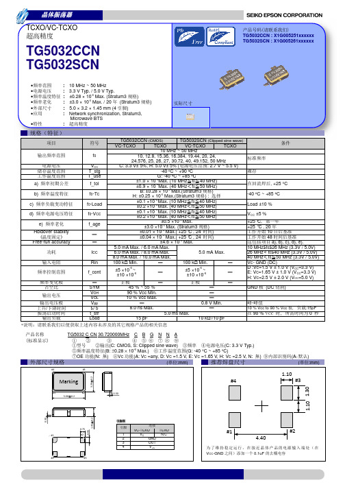
1. 恒温晶体振荡器(OCXO)------------------------------------------------------------------第04页~第30页2. 温补晶体振荡器(TCXO)--------------------------------------------------------------------第31页~第41页3. 压控晶体振荡器(VCXO)-------------------------------------------------------------------第42页~第43页FCOX2系列<超高稳定度,超低老化率,50.8mm 50.8mm H mm>-----------------------------------------第05页~第06页 FCOX3系列<极低相位噪声,50.8mm 50.8mm 19.0mm,SMA-F>-----------------------------------------第07页~第08页 FCOX4系列<超低相位噪声,38.1mm 38.1mm 12.7mm>--------------------------------------------------第09页~第10页 FCOX5系列<超低相位噪声,38.1mm 38.1mm 12.7mm>--------------------------------------------------第11页~第12页 FCOX7系列<超低相位噪声,小体积,25.4mm 25.4mm 12.7mm>-----------------------------------------第13页~第14页 FCOX8系列<超低相位噪声,超小体积,20.320.39.7(or 11.4)mm>--------------------------------------第15页~第16页FCOX9系列<极低相位噪声,试验室级应用,74.6344.4525.4mm>--------------------------------------第17页~第18页FCOX10系列<低相位噪声,超小体积,25.415.249.7(or 11.4)mm>--------------------------------------第19页~第20页FCOX12系列<低相位噪声,表面贴,25.522.210.0mm>---------------------------------------------------第21页~第22页FCOX17系列<超低相位噪声,35.4mm 26.7mm 12.7(or 13.6)mm>--------------------------------------第23页~第24页 FCOX18系列<超高稳定度,超低老化率,51.3.0(or 25.4)mm>-----------------------------------第25页~第26页 FCOX101系列<超低功耗,超小体积,低相位噪声,插件,21.013.6.5mm>------------------------------第27页~第28页FCOX102系列<超低功耗,超小体积,低相位噪声,表面贴,25.415.24.7mm>-------------------------第29页~第30页FCTX8系列<超低相位噪声,20.3mm 20.3mm 9.7(or 11.4)mm>------------------------------------------第32页~第33页 FCTX9系列<超低相位噪声,25.4mm 15.24mm 9.7(or 11.4)mm>----------------------------------------第34页~第35页 FCTX10系列<超低相位噪声,表面贴,27.4mm 17.8mm 5.9mm>-----------------------------------------第36页~第37页 FCTX12系列<超低相位噪声,表面贴,25.5mm 22.2mm 6.7mm>-----------------------------------------第38页~第39页 FCTX13系列<低相位噪声,超小体积,表面贴,17.014.0 6.0mm>-----------------------------------------第40页~第41页FCVX3系列<低相位噪声,表面贴,27.4mm 17.8mm 5.9mm>---------------------------------------------第42页~第43页×××××××××××××××××××××41.3×19××8××8××××××××××××晶体振荡器QUARTZ CRYSTAL OSCILLATOR5. 倍频晶体振荡器(MXO)---------------------------------------------------------------------第51页~第55页MXO4系列<极低相位噪声,极低杂散,50.0mm 50.0mm mm>-------------------------------------------第52页~第53页MXO7系列<双路输出,低相位噪声,低杂散,50.8mm 50.8mm mm>------------------------------------第54页~第55页××H ××H 倍频晶体振荡器MULTIPLIED CRYSTAL OSCILLATOR4. 抗振晶体振荡器(AVXO)-------------------------------------------------------------------第44页~第50页AVXO3系列<抗振设计,优秀动态相位噪声,38.138.119.0(or 16.0)mm>-------------------------------第45页~第46页 AVXO4系列<抗振设计,优秀动态相位噪声,38.138.119.0(or 16.0)mm>-------------------------------第47页~第48页 AVXO6系列<抗振设计,卓越动态相位噪声,50.850.827.0mm>-----------------------------------------第49页~第50页××××××抗振晶体振荡器ANTI-VIBRATION CRYSTAL OSCILLATORNEW !NEW !NEW !NEW !6. 锁相晶体振荡器(PLXO)----------------------------------------------------------------第56页~第60页PLXO1系列<内置PLL,极低相位噪声,50.8mm 50.8mm 19.0mm,SMA>----------------------------第57页~第58页 PLXO2系列<内置PLL,小体积,低相位噪声,35.4mm 26.7mm 12.7mm>----------------------------第59页~第60页××××锁相晶体振荡器PHASE LOCKED CRYSTAL OSCILLATOR7. 客户订货信息表---------------------------------------------------------------------------------第61页客户订货信息表8. 新产品发布专栏--------------------------------------------------------------------------------第62页新产品发布专栏---NEW PRODUCTS RELEASE敬请关注!-恒温晶体振荡器<OVEN CONTROLLED CRYSTAL OSCILLATOR>超短预热时间FCOX350.8mm X 50.8mm X19.1mmFCOX17FCOX7FCOX8FCOX10FCOX10121.0X13.6X8.5mmFCOX10225.4X15.24X8.7mmNEW !NEW !NEW!FCOX12NEW !OCXOFCOX2产品数据手册 Rev A电性能参数输出信号(客户定义)标称频率 5~20MHz 输出波形 正弦波或方波输出功率,正弦波 0~+13.0dBm 初始频率准确度 ±0.05~±0.3ppm 谐波,正弦波 -30dBc max.杂波,正弦波 -70dBc max.相位噪声(客户定义)OSC @ 10MHz@1Hz -85~-110dBc/Hz @10Hz -110~-140dBc/Hz @100Hz -135~-155dBc/Hz @1KHz -145~-165dBc/Hz @10KHz -150~-166dBc/Hz @100KHz -150~-168dBc/Hz @1MHz -150~-168dBc/Hz稳定度(客户定义)温度稳定度 ±短期稳定度 ±1E-10~±5E-13/s 老化率 ±1E-7~±1E-8/y50~±0.1ppb 电源电压(客户定义)工作电压 +5.0V 或+12.0V 或+15.0V 最大工作电流 500~1500mA max.稳定工作电流 200~700mA max.预热特性 1~15分钟,达到±1E-7~±1E-8频率调节(客户定义)频率调节方式 电调节(EFC )压控电压范围 0~2.5~5.0V 频率牵引范围 ±0.3~±1.0ppm 频率牵引斜率 正输入阻抗 100k Ω min.环境适应性(客户定义)工作温度范围 最宽-55℃~+85℃机械冲击 GJB-360B,方法213,15g,11ms,半正弦温度冲击 GJB-360B,方法107,-55℃~+85℃,5次2随机振动 GJB-360B,方法214,0.04g /Hz,3个轴向存储温度范围-55℃~+100℃.标签纸,位于产品外壳顶部,包括生产厂家标识、产品型号、标称频率、序列号、生产日期等信息。
txc贴片无源晶振 3225晶振 7M12000039规格书

(1) TXC requires one copy returned with signature and title of authorized individual that signifies acceptanceof the attached specifications.(2) Orders received and accepted by TXC after return of signed copy of specification will be produced perthese specifications.(3) Any changes to these specifications must be agreed upon by both parties and new revision of theProduct Specification Sheet will be issued.(4) Any issuance of purchase order prior to consigning back the Approval page of "Specification Sheets"from customers will be regarded as the agreement on the contents of these specifications.Attachment: Product Specification Sheet12345CUSTOMER SIGNATURE & DateDATE:PM / SALES :CUSTOMER P/N :REVISION :A9TXC P/N:7M12000039NOMINAL FREQ.:12.000000MHz PRODUCT TYPE :SMD SEAM SEALING X'TAL 3.2×2.5RoHS CompliantTEL : 886-2-2894-1202 , 886-2-2895-2201 FAX : 886-2-2894-1206 , 886-2-2895-6207 SPECIFICATION FOR APPROVALCUSTOMER :TEL : 886-2-2894-1202 , 886-2-2895-2201 FAX : 886-2-2894-1206 , 886-2-2895-6207 25-May-09A82ECN-08P123001A93,4ECN-09P052503RevRevise pageRevise contentsDateRef.No.A1N/A ReviserInitial released7-Nov-07N/AYachuan MiaoYachuan Miao Package Change25-May-09Yachuan MiaoRr Change: 200 ohm to 100 ohm 30-Dec-08ELECTRICAL SPECIFICATIONSStandard atmospheric conditionsUnless otherwise specified, the standard range of atmospheric conditions for making measurement and tests are as follow:Ambient temperature :25±5 Relative humidity:40%~70%If there is any doubt about the results, measurement shall be made within the following limits:Ambient temperature :25±3 Relative humidity :40%~70%Measure equipmentElectrical characteristics measured by HP E5100A or equivalent.Crystal cutting typeThe crystal is using AT CUT (thickness shear mode). Unit Weight: 0.018±0.001 g/pcs1Nominal Frequency 2Oscillation Mode 3Load Capacitance 4Frequency Tolerance 5Frequency Stability 6Operating Temperature 7Aging 8Drive Level9Effective Resistance Rr 10Shunt Capacitance C011Insulation Resistance 12Storage Temperature Range--30~85at 25 ± 3±20ppm Over Operating Temp. Range (Reference 25 )ppm -ParametersSYM.Electrical Spec.MINTYPE MAXUNITS -±20--FundamentalMHz CL 18pF -Notes FL 12.000000-- -1st Year -ppm Ω-DL µW --10-Rr -100-±5--~C0--pF 5M Ω at DC 100V -50085---40。
爱普生(EPSON)高精度晶体振荡器TG5032CCN TG5032SCN规格书
6.0 mA Max. / 8.0 mA Max.
5.0 mA Max.
8.0 mA Max. / 10.0 mA Max.
100 kΩ Min.
100 kΩ Min.
±5 ×10⁻⁶ ~ ±10 ×10-6
±5 ×10⁻⁶ ~ ±10 ×10-6
, +25 °C
-40 ºC ~ +85 ºC
Load ±10 %
): 40 MHz) 50 MHz) 40 MHz) 50 MHz)
±3.0 ×10⁻⁶ Max. (Stratum3 )
±0.01 × 10⁻⁶ Max.( +25 °C , 24
)
±0.04 × 10⁻⁶ Max.( +25 °C , 24
)
±4.6 × 10⁻⁶ Max.
5.0 mA Max. / 6.0 mA Max.
90 % VCC
:15pF
0
―― (
― ― ― ― ― TG5032 C CN 30.720000MHz C B G N N A
)― ― ― ― ― OE
(C: CMOS, S: Clipped sine wave)
―
(C: 3.3 V Typ.)
(B: ±0.28 × 10⁻⁶ Max.)
(G: -40 °C ~ +85 °C)
(N: ) VC (A: VC =any, D: VC =1.5 V, E: VC =1.65 V, H: VC =2.5 V, N: )
( :mm)
#4
#3
Marking
#4
(A极 ) ( :mm)
1.10 #3
3.20±0.2
#1
高可靠性混合VCXO晶体振荡器规格说明书

REV DESCRIPTION DATEPREPAPPDG EC20973 7/10/23SMLT/AJOscillator Specification, Hybrid VCXOACMOS, 9x14 mm, J-Lead MOUNT HOLLY SPRINGS, PA 17065 Hi-Rel Standard THE RECORD OF APPROVAL FOR THISDOCUMENT IS MAINTAINED ELECTRONICALLYCODE IDENT NO SIZE DWG. NO.REV1. SCOPE1.1General. This specification defines the design, assembly, and functional evaluation of highreliability, VCXO’s produced by Vectron. Devices delivered to this specification represent the standardized Parts, Materials and Processes (PMP) Program developed, implemented, andcertified for advanced applications and extended environments.1.2Applications Overview. The designs represented by these products were primarily developedfor the MIL-Aerospace community. The lesser Design Pedigrees and Screening Optionsimbedded within DOC206218 bridge the gap between Space and COTS hardware by providing custom hardware with measures of mechanical, assembly and reliability assurance needed for Military or Ruggedized COTS environments.2.APPLICABLE DOCUMENTS2.1Specifications and Standards. The following specifications and standards form a part of thisdocument to the extent specified herein. The issue currently in effect on the date of quotation will be the product baseline, unless otherwise specified. In the event of conflict between thetexts of any references cited herein, the text of this document shall take precedence.MilitaryControlled, General Specification For MIL-PRF-55310 Oscillators,CrystalMicrocircuits, General Specification ForMIL-PRF-38534 HybridStandardsMIL-STD-202 Test Method Standard, Electronic and Electrical Component PartsMIL-STD-883 Test Methods and Procedures for MicroelectronicsOtherDOC206251 Test Specification, DOC206218 Hybrids, Hi-Rel StandardQSP-90100 Quality Systems Manual, VectronDocuments,Materials and Processes, Hi-Rel XOCommonDOC011627 IdentificationSpecificationDOC203982 DPAElectrostatic Discharge PrecautionsforQSP-91502 ProcedureDOC208191 Enhanced Element Evaluation for Space Level Hybrid OscillatorsDOC220429 Packaging Standards, Hi-Rel SeriesREQUIREMENTS3. GENERAL3.1 Classification. All devices delivered to this specification are of hybrid technology conformingto Type 2, Class 2 of MIL-PRF-55310. Primarily developed as a Class S equivalentspecification, options are imbedded within it to also produce Class B, Engineering Model and Ruggedized COTS devices. Devices carry a Class 2 ESDS classification per MIL-PRF-38534.3.2 Item Identification. See paragraph 7.1 for part number configuration.3.3 Absolute Maximum Ratings.a. Supply Voltage Range (V CC): -0.5Vdc to +7.0Vdcb. Storage Temperature Range (T STG): -65°C to +125°Cc. Junction Temperature (T J): +175°Cd. Lead Temperature (soldering, 10 seconds): +300°Ce. Output Source/Sink Current: ±70 mA3.4 Design, Parts, Materials and Processes, Assembly, Inspection and Test.3.4.1 Design. The ruggedized designs implemented for these devices are proven in military andspace applications under extreme environments. The design utilizes a 4-point crystal mount in compliment with Established Reliability (MIL-ER) componentry. When specified, radiationtolerant active devices up to 100krad(Si) (RHA level R) can be included without altering thedevice’s internal topography.3.4.1.1 Design and Configuration Stability. Barring changes to improve performance by reselectingpassive chip component values to offset component tolerances, there will not be fundamental changes to the design or assembly or parts, materials, and processes after first product delivery of that item without notification.3.4.1.2 Environmental Integrity. Designs have passed the environmental qualification levels of MIL-PRF-55310.3.4.2 Prohibited Parts, Materials and Processes. The items listed are prohibited for use in highreliability devices produced to this specification.a. Gold metallization of package elements without a barrier metal.b. Zinc chromate as a finish.c. Cadmium, zinc, or pure tin external or internal to the device.d. Plastic encapsulated semiconductor devices.e. Ultrasonically cleaned electronic parts.f. Heterojunction Bipolar Transistor (HBT) technology.g. ‘getter’ materials3.4.3 Assembly. Manufacturing utilizes standardized procedures, processes, and verificationmethods to produce MIL-PRF-55310 Class S / MIL-PRF-38534 Class K equivalent devices.MIL-PRF-38534 Group B Option 1 in-line inspection is included on radiation hardened partnumbers to further verify lot pedigree. Devices are handled in accordance with Vectrondocument QSP-91502 (Procedure for Electrostatic Discharge Precautions). Elementreplacement will be as specified in MIL-PRF-38534, Rev L.3.4.4 Inspection. The inspection requirements of MIL-PRF-55310 apply to all devices delivered tothis document. Inspection conditions and standards are documented in accordance with theQuality Assurance, ISO-9001 and AS9100 derived, System of QSP-90100.3.4.5 Test. The Screening test matrix of Table 4 is tailored for selectable-combination testing toeliminate costs associated with the development/maintenance of device-specific documentation packages while maintaining performance integrity.3.4.6 Marking. Device marking shall be in accordance with the requirements of MIL-PRF-55310. Inaddition, when devices are identified with laser marking, the Resistance to Solvents testspecified in MIL-PRF-55310 Group C, Mil-PRF-55310 Qualification or MIL-PRF-38534Group B Inspection will not be performed.3.4.7 Ruggedized COTS Design Implementation. Design Pedigree “D” devices (see ¶ 5.2) use thesame robust designs found in the other device pedigrees. They do not include the provisions of traceability or the Class-qualified componentry noted in paragraphs 3.4.3 and 4.1.REQUIREMENTS4. DETAIL4.1 Components4.1.1 Crystals. Cultured quartz crystal resonators are used to provide the selected frequency for thedevices. The optional use of Premium Q swept quartz can, because of its processing to remove impurities, be specified to minimize frequency drift when operating in radiation environments.In accordance with MIL-PRF-55310, the manufacturer has a documented crystal elementevaluation program.4.1.2 Passive Components.4.1.2.1 For Design Pedigree E, where available, resistors shall be Established Reliability, Failure RateR (as a minimum) and capacitors shall be Failure Rate S. Where resistors and capacitors arenot available as ER parts, and for all other passive components, the parts shall be fromhomogeneous manufacturing lots that have successfully completed the Enhanced ElementEvaluation of DOC208191 which meets the requirements of Mil-PRF-38534 Revision L forClass K.4.1.2.2 For Design Pedigrees R, V and X, where available, resistors shall be Established Reliability,Failure Rate R (as a minimum) and capacitors shall be Failure Rate S. Where resistors andcapacitors are not available as ER parts, and for all other passive components, the parts shall be from homogeneous manufacturing lots that have successfully completed the Class K Element Evaluation of Mil-PRF-38534 Revision K for Class K.4.1.2.3 For Design Pedigrees B and C, all passive elements shall comply with the Element Evaluationrequirements of Mil-PRF-55310 Class B as a minimum.4.1.2.4 For Design Pedigree D, the passive elements will be COTs level or higher.4.1.2.5 When used, inductors will be open construction and may use up to 47-gauge wire.4.1.3 Microcircuits.4.1.3.1 For Design Pedigree E, the microcircuits shall be from homogeneous wafer lots that meet theEnhanced Element Evaluation requirements in DOC208191 and meet the requirements of Mil-PRF-38534 Revision L for Class K.4.1.3.2 For Design Pedigree R, V and X, microcircuits shall be from homogeneous wafer lots that havesuccessfully completed the MIL-PRF-38534, Revision K Lot Acceptance Tests for Class K. 4.1.3.3 For Design Pedigrees B and C, microcircuits are procured from wafer lots that havesuccessfully completed the MIL-PRF-55310 Lot Acceptance Tests for Class B as a minimum.4.1.3.4 For Design Pedigree D, microcircuits can be COTs level or higher.4.1.4 Semiconductors (Varactor Diode)4.1.4.1 For Design Pedigree E, the semiconductors shall be from homogeneous wafer lots that meetthe Enhanced Element Evaluation requirements in DOC208191.4.1.4.2 For Design Pedigree R, V and X, semiconductors shall be from homogeneous wafer lots thathave successfully completed the MIL-PRF-38534, Revision K Lot Acceptance Tests for Class K devices as a minimum.4.1.4.3 For Design Pedigree B and C, semiconductors are procured from wafer lots that havesuccessfully completed the MIL-PRF-55310 Lot Acceptance Tests for Class B devices as a minimum.4.1.4.4 For Design Pedigree D, semiconductors can be COTs level or higher.4.1.5 Radiation. Microcircuits for Design Pedigrees E, R and V are certified to 100krad(Si) totalionizing dose (TID), RHA level R (2X minimum margin). NSC, as the original 54ACT designer, rates the SEU LET up to 40 MeV and SEL LET up to 120MeV for the FACT™ family (AN-932). Vectron conducted additional SEE testing in 2008 to verify this performance since our lot wafer testing does not include these parameters and determinations. Varactor diodes are considered radiation tolerant by design.4.1.6 Packages. Packages are procured that meet the construction, lead materials and finishes asspecified in MIL-PRF-55310. All leads are Kovar with gold plating over a nickel underplate.Package lots are evaluated in accordance with the requirements of MIL-PRF-38534. Vectronwill not perform Salt Spray testing as part of MIL-PRF-55310 Group C/Qualification. Inaccordance with MIL-PRF-55310, package evaluation results for salt atmosphere will besubstituted for Salt Spray testing during MIL-PRF-55310 Group C/Qualification.4.1.7 Traceability and Homogeneity. All design pedigrees except option D have active device lotsthat are traceable to the manufacturer’s individual wafer; all other elements and materials aretraceable to their manufacturer and incoming inspection lots. Design pedigrees E, R, V and Xhave homogeneous material. In addition, swept quartz crystals are traceable to the quartz barand the processing details of the autoclave lot. A production lot, as defined by Microchip, is all oscillators that have been kitted and built as a single group. The maximum deliverablequantity with a single lot date code is 225 units. Order quantities that exceed 225 units will be delivered in multiple lot date codes with deliveries separated by 2 weeks. If applicable, eachproduction lot will be kitted with homogeneous material which is then allocated acrossmultiple lot date code builds to satisfy the deliverable order quantity. When ordered, Group CInspection, lot qualifications, and/or DPA will be performed on the first build lot within theproduction lot unless otherwise stated on the purchase order.4.2 Mechanical.4.2.1 Package Outline. See Figure 1.4.2.2Thermal Characteristics. The worst-case thermal characteristics are found in Table 3.4.2.3Lead Forming. When the lead forming option is specified, the applicable leak test specified inscreening will be performed after forming.4.3 Electrical.4.3.1 Input Power. Devices are available with an input voltage of either +5.0 Vdc (±5%) or +3.3 Vdc(±5%). Current is measured, no load, at maximum rated operating voltage.4.3.2 Temperature Range. Operating range is -40°C to +85°C.4.3.3 Absolute Pull Range. Absolute pull range is defined as the minimum guaranteed amount theVCXO can be varied about the center frequency (fo). It accounts for degradations includingtemperature stability (-40°C to +85°C), aging (15 years), radiation effects, power supplyvariations (±5%) and load variations (±10%).4.3.4 Frequency Aging. When tested in accordance with MIL-PRF-55310 Group B inspection, the15-year aging projection shall not cause the minimum APR limit to be exceeded.4.3.5 Operating Characteristics. Symmetrical square wave limits are dependent on the devicefrequency and are in accordance with Table 1. Waveform measurement points and logic limits are in accordance with MIL-PRF-55310. Start-up time is 10.0 msec. maximum.4.3.6Output Load. ACMOS (10kΩ, 15pF) test loads are in accordance with MIL-PRF-55310.5.QUALITY ASSURANCE PROVISIONS AND VERIFICATION5.1Verification and Test. Device lots shall be tested prior to delivery in accordance with theapplicable Screening Option letter as stated by the 15th character of the part number. Table 4tests are conducted in the order shown and annotated on the appropriate process travelers and data sheets of the governing test procedure. For devices that require Screening Options thatinclude MIL-PRF-55310 Group A testing, the Post-Burn-In Electrical Test and the Group AElectrical Test are combined into one operation.5.1.1Screening Options. The Screening Options, by letter, are summarized as:A Modified MIL-PRF-38534 Class KB Modified MIL-PRF-55310 Class B Screening & Group A Quality ConformanceInspection (QCI)C Modified MIL-PRF-55310 (Rev E) Class S Screening & Group A QCID Modified MIL-PRF-38534 Class K with Group B AgingE Modified MIL-PRF-55310 Class B Screening, Groups A & B QCIF Modified MIL-PRF-55310 (Rev E) Class S Screening, Groups A & B QCIG Modified MIL-PRF-55310 Class B Screening & Post Burn-in NominalElectricalsS MIL-PRF-55310 (Rev F) Class S Screening & Groups A & B QCIX Engineering Model (EM)5.2 Optional Design, Test and Data Parameters. The following is a list of design, assembly,inspection, and test options that can be selected or added by purchase order request.a. Design Pedigree (choose one as the 5th character in the part number):(E) Enhanced Element Evaluation, (MIL-PRF-38534 Rev L for Class K components asspecified in DOC208191), 100krad die, Premium Q Swept Quartz(R) Hi-Rel design w/ 100krad Class K die, Premium Q Swept Quartz(V) Hi-Rel design w/ 100krad Class K die, Non-Swept Quartz(X) Hi-Rel design w/ Non-Swept Quartz, Class K die(B) Hi-Rel design w/ Swept Quartz, Class B die(C) Hi-Rel design w/ Non-Swept Quartz, Class B die(D) Hi-Rel design w/ Non-Swept Quartz and commercial grade componentsb. Input Voltage/APR, (L) for +3.3V/±30ppm, (N) for +5.0V/±30ppm and (W) for+5.0V/±50ppm as the 14th characterc. Not Usedd. Radiographic Inspectione. Group C Inspection: MIL-PRF-55310, Rev E (requires 8 destruct specimens)f. Group C Inspection: MIL-PRF-55310, Rev F (requires 8 destruct specimens, includesRandom Vibration, MIL-STD-883, Method 1014 Leak Test and Life Test)g. Group C Inspection: In accordance with MIL-PRF-38534, Table C-Xc, Condition PI(requires 8 destruct specimens – 5 pc. Life, 3 pc. RGA). Subgroup 1 fine leak test to beperformed per MIL-STD-202, Method 112, Condition C.h. Internal Water-Vapor Content (RGA) samples and test performancei. MTBF Reliability Calculationsj. Worst Case Circuit Analysis: (unless otherwise specified, MIL-HDBK-1547)k. Derating and Thermal Analysis (unless otherwise specified, MIL-HDBK-1547 with TjMax = +105°C; Derated Maximum Operating Temp = Tj Max – ΔTj)l. Process Identification Documentation (PID)m. Customer Source Inspection (pre-crystal mount pre-cap, post-crystal mount pre-cap and final). Due to components being mounted underneath the crystal blank, pre-crystalmount pre-cap inspection should be considered.n. Destruct Physical Analysis (DPA): MIL-STD-1580 with exceptions as specified in Vectron DOC203982.o. Qualification: In accordance with MIL-PRF-55310, Rev F, Table IV (requires 16 destruct specimens). Includes Group III, SG1 through SG6 only. ESD (SG7) notperformed.p. Qualification: In accordance with EEE-INST-002, Section C4, Table 3, Level 1 or 2 (requires 11 destruct specimens)q. High Resolution Digital Pre-Cap Photographs (20 Megapixels minimum)r. Hot solder dip of leads with Sn63/Pb37 solder prior to shipping5.2.1 NASA EEE-INST-002. A combination of Design Pedigree R, Option S Screening, andQualification per EEE-INST-002, Section C4, Table 3, meet the requirements of Level 1 and Level 2 device reliability.5.3Test Conditions. Unless otherwise stated herein, inspections are performed in accordance withthose specified in MIL-PRF-55310. Process travelers identify the applicable methods,conditions, and procedures to be used. Examples of electrical test procedures that correspond to MIL-PRF-55310 requirements are shown in Table 2.5.3.1 When MIL-PRF-55310, Revision F was being reviewed for release by manufacturers andusers, Vectron and other organizations recommended that burn-in delta limits not beapplied to logic level measurements due to the inconsistency in attempting to measuresmall changes in logic levels which inherently have ringing in the signal. This isespecially true in higher frequency oscillators measured in automated test systems thatare affected by cable length that is not representative of the user’s application and contactresistance in test fixtures that do not provide a consistent Vcc or Ground connection. Theexact test setup conditions may vary slightly from pre-burn-in to post-burn-in and causesmall artificial deltas in logic level measurements that are not indicative of an issue. Anysignificant changes in logic levels will be reflected in supply current deltas and/or logiclevels that exceed the min/max limits. As a result, we take exception to MIL-PRF-55310,Revision F, Para. 4.4.5 and the delta limit for Output Low Level as specified in 4.4.5(c)shall not be applied to Burn-in PDA.5.4Deliverable Data. The manufacturer supplies the following data, as a minimum, with each lotof devices:a. As applicable to the Screening Option chosen, completed assembly and screening lottravelers, screening data, including radiographic images, and rework history.b. Electrical test variables data, identified by unique serial number.c. Special items when required by purchase order such as Group C, DPA, and RGA data.d. For Design Pedigrees E, R, V, and X, traceability, component LAT, enclosure LAT,and wafer lot specific RLAT data for non-SMD active devices (if applicable).e. Certificate of Conformance.5.5Discrepant Material. All MRB authority resides with the procuring activity.5.6Failure Analysis. Any failure during Qualification or Group C Inspection will be evaluated forroot cause. The customer will be notified after occurrence and upon completion of theevaluation.6.PREPARATION FOR DELIVERY6.1Packaging. Devices will be packaged in a manner that prevents handling and transit damageduring shipping. Devices will be handled in accordance with MIL-STD-1686 for Class 1devices. Devices will be packaged for transport in accordance with DOC220429. Please note that “one unit per package” is available for a fee; however, this service must be requested aspart of the official RFQ.7.ORDERING INFORMATION7.1 Ordering Part Number. The ordering part number is made up of an alphanumeric series of15 characters. Design-affected product options, identified by the parenthetic letter on theOptional Parameters list (¶ 5.2a and b), are included within the device part number.The Part Number breakdown is described as:5116 R 10M00000 L F7.1.1 Model Number. The device model number is the four (4) digit number 5116.7.1.2 Design Pedigree. Class S variants correspond to either letter “E”, “R”, “V” or “X” and aredescribed in paragraph 5.2a. Class B variants correspond to either letter “B” or “C” and aredescribed in paragraph 5.2a. Ruggedized COTS, using commercial grade components,corresponds to letter “D”.7.1.3Output Frequency. The nominal output frequency is expressed in the format as specified inMIL-PRF-55310 utilizing eight (8) characters.7.1.4 Input Voltage (APR). “L” for +3.3V (±30ppm), “N” for +5.0V (±30ppm) and “W” for +5.0V(±50ppm) as the 14th character.7.1.5 Screening Options. The 15th character is the Screening Option (letter A thru G, S or X) selectedfrom Table 4.7.2Optional Design, Test and Data Parameters. Optional test and documentation requirementsshall be specified by separate purchase order line items (as listed in ¶ 5.2c thru s).Frequency Range: 1.0 MHz to 100.0 MHzTemperature Range: -40°C to +85°CPower Supply (Vcc): +3.3Vdc ±5% or +5.0Vdc ±5%Absolute Pull Range: ±30 ppm or ±50 ppm (+/-30 ppm only for +3.3Vdc)Control Voltage (Vc) Range: 0.3V to +3.0V with Vcc = +3.3VControl Voltage (Vc) Range: 0.5V to +4.5V with Vcc = +5.0VSlope: PositiveLinearity: 10% max.F vs. V Gain: 45 ppm/V min. to 105 ppm/V max.Start-up Time: 10.0 ms max.Frequency Range (MHz)Current (mA)(max. no load)Rise / FallTimes 1/(ns max.)Duty Cycle 1/(%)+5.25V +3.465V1 – 15 15 8 10 45 to 55>15 – 40 20 15 5 40 to 60>40 – 60 35 20 5 40 to 60>60 – 85 45 25 3 40 to 60>85 – 100 55 35 3 40 to 601/. Waveform measurement points and logic limits are in accordance with MIL-PRF-55310, Para 3.6.20.3.TABLE 1 - Electrical Performance CharacteristicsOPERATION LISTING REQUIREMENTS ANDCONDITIONS@ all Electrical TestsInput Current (no load) MIL-PRF-55310, Para 4.8.5.1 ************************.MIL-PRF-55310, Para 4.8.6 Output Logic Voltage Levels MIL-PRF-55310, Para 4.8.21.3 Rise and Fall Times MIL-PRF-55310, Para 4.8.22 Duty Cycle MIL-PRF-55310, Para 4.8.23 Frequency Deviation MIL-PRF-55310, Para 4.8.31.1 Linearity MIL-PRF-55310, Para 4.8.31.5Nominal conditions only@ Post Burn-In Electrical onlyOvervoltage Survivability MIL-PRF-55310, Para 4.8.4 Initial Freq. – Temp. Accuracy MIL-PRF-55310, Para 4.8.10.1 Freq. – Voltage Tolerance MIL-PRF-55310, Para 4.8.14 Start-up Time (fast/slow start) MIL-PRF-55310, Para 4.8.29TABLE 2 - Electrical Test ParametersModel # Thermal ResistanceJunction to Caseθjc (°C / W) Δ Junction Temp.T j(°*********)Weight(Grams)5116 31.62 9.13 1.2 Note: The maximum power from Table 2 is used to calculate the worst case Δ JunctionTemperature.TABLE 3 - Typical Thermal Characteristics and WeightTable 3a – Typical Phase Noise at 16MHz, 3.3VTable 3b – Typical Phase Noise at 16MHz, 5.0VTable 3c – Typical Phase Noise at 50MHz, 3.3VTable 3e – Typical Phase Noise at 80MHz, 3.3VTable 3g – Typical Phase Noise at 100MHz, 5.0VPin ConnectionsVoltage1 Control2 GND/Case3 Output4 VccFIGURE 1Model 5116 Package OutlineAPPENDIX A Recommended Land PatternModel 5116。
深圳市晶发电子有限公司石英晶体谐振器(柱状)说明书

产品规格书SPECIFICATION产品名称石英晶体谐振器Description Crystal Unit型号·标称频率Type·Nominal Frequency20612.000MHz规格书号Specification.JFWSG12010A104C制作DESIGNEDBY杨阳审核CHECKEDBY何珍批准APPROBEDBY肖琳石英晶体谐振器(柱状)RoHS Compliant Standard TDXLF-206-12.000MHz10PFSTANDARD SPECIFICATIONS標準規格标称频率Nominal Frequency12.000MHz负载电容Load Capacitance10pF工作温度范围Operating Temperature-20℃~+70℃频率公差Frequency Tolerance±10ppm25℃温度频差±10PPM(-20~+70之间)等效阻抗<80Ω激励电平Level of Drive50U W绝缘电阻:50M(插脚间加DC100V±5V)年老化率Aging±5ppm/year静电容<5PF可靠性1Reliability(Mechanical and Environmental Endurance)Page1of2 NO Test Items Test Method and Condition Requirements1振動Vibration (1)振動頻Vibration Frequency10to55Hz(2)振動幅度Vibration Amplitude1.5mm(3)周期Cycle Time1-2min(10-55-10Hz)(4)振動方向Direction X.Y.Z(5)振動時間Duration2h/each direction頻率變化最大:±10ppm覆蓋The dipped surface of theleads should be at least95%covered with continuous newsolder coating2衝擊Shock 從75cm高的地方自由跌落3次到30mm厚的硬木板上3Times free drop from75cmheight to hard wooden board of thicknessmore than30mm頻率變化最大:±10ppmFrequency Change:±10ppm Max.電阻變化最大:5kohmResistance Change:5kohm Max.3氣密性Leakage 晶體放入氦加壓罐內,充入氦氣壓力0.5-0.6Mpa保持1小時;然後使用氦質譜檢漏儀測試。
MXL 晶体振荡器产品参考表说明书

C L K O S CV C X OT C X OV C T C X OM C FList of products24.000 MHz ~ 80.000 MHz20.000 MHz ~ 80.000 MHz16.000MHz ~ 80.000 MHz12.000 MHz ~ 150.000 MHz9.840 MHz ~ 50.000 MHz10.000MHz ~ 300.000 MHz8.000MHz ~ 60.000 MHz10.000MHz ~ 50.000 MHz9.000MHz ~ 150.000 MHz12.000 MHz ~ 50.000 MHz10.000 MHz ~ 67.000 MHz8.000MHz ~ 10.000 MHz1.20.31.61.60.452.02.00.52.52.50.653.22.50.83.23.20.855.03.21.3 / 1.55.03.21.15.03.51.06.03.50.96.03.51.26.05.01.17.0 / 7.5C L K O S CV C X O T C X O V C T C X O M C F6.000 MHz ~ 70.000 MHz6.000 MHz ~ 70.000 MHz4.000 MHz ~ 50.000 MHz3.579545 MHz ~ 25.000 MHz3.579545 MHz ~ 25.000 MHz3.579545 MHz ~ 32.000 MHz3.579545 MHz ~ 32.000 MHz3.579545 MHz ~ 32.000 MHz3.579545 MHz ~ 61.000 MHz5.01.17.0 / 7.55.01.17.0 / 7.54.51.88.05.51.5 / 1.811.85.02.111.04.33.612.44.74.213.04.74.213.04.74.312.43.112.44.72.612.44.710.52.15.011.35C L K O S CV C X OT C X OV C T C X OM C FList of products3.579545 MHz ~ 61.000 MHz3.579545 MHz ~ 61.000 MHz6.000 MHz ~ 200.000 MHz 10.000 MHz ~ 200.000 MHz20.000 MHz ~ 200.000 MHz1.000 MHz ~ 1.200 MHz1.84320 MHz ~ 200.000 MHz1.84320 MHz ~ 200.000 MHz10.55.011.352.510.55.011.353.57.83.1 / 2.88.02.55.88.03.1 / 2.82.54.48.03.1 / 2.82.58.07.97.13.2 / 2.76.03.2 / 2.77.97.14.57.97.13.2 / 2.711.54.913.5 / 11.54.013.5 / 11.211.34.9C L K O S C V C X O T C X O V C T C X OM C F List of products32.768 kHz 32.768 kHz 32.768 kHz 32.768 kHz 32.768 kHz 32.768 kHz 32.768 kHz 32.768 kHz 30.000 kHz 100.000 kHz32.768 kHz 32.768 kHz 1.20.552.01.50.83.21.81.04.91.51.47.09.0 2.543.02.58.32.542.31.24.73.72.47.94.1C L K O S CV C X OT C X OV C T C X O M C FList of products32.768 kHz 32.768 kHz 32.768 kHz 30.000 kHz ~ 100.000 kHz 30.000 kHz ~ 100.000 kHz 1.45.01.96.01.96.01.24.7X T A LV C X OT C X O V C T C X O M C F List of productsCMOSCMOSCMOSCMOS CMOS CMOSCMOSCMOSCMOSCMOSCMOSCMOS1.60.752.02.00.92.52.51.03.22.00.92.52.51.03.23.21.25.05.01.37.02.00.92.52.51.03.23.21.055.05.01.37.01.60.752.5XTALVCXOTCXOVCTCXOMCFList of productsCMOS CMOS CMOSLVPECL LVPECL LVPECLLVDS LVDS LVDSHCSL HCSL HCSL5.01.37.03.21.055.02.51.03.25.01.57.02.50.93.23.21.25.05.01.57.02.50.93.23.21.25.05.01.57.02.50.93.23.21.25.0X T A LV C X O T C X O V C T C X O M C F List of productsCMOS CMOS CMOS CMOS CMOS CMOS 2.50.93.21.51.03.22.00.92.52.51.03.23.21.25.05.01.37.0XTALCLKOSCTCXOVCTCXOMCFList of productsCMOS CMOS CMOSCMOS CMOSCMOS LVPECL LVPECLLVPECL LVDS2.00.92.52.01.03.22.50.93.23.21.25.03.21.25.05.01.67.05.01.57.03.21.25.05.01.77.02.50.93.2CMOS5.01.77.0LVDS3.21.25.0X T A LC L K O S CT C X O V C T C X O M C FXTALCLKOSCVCXOVCTCXOMCFList of products12CLIPPED SINE CLIPPED SINE CLIPPED SINECLIPPED SINE CLIPPED SINE CLIPPED SINECLIPPED SINECLIPPED SINE CLIPPED SINECLIPPED SINE CLIPPED SINE CLIPPED SINE1.60.72.01.60.72.01.60.72.01.60.72.01.60.72.01.60.72.02.00.82.52.00.82.5VcontrolX T A LC L K O S CV C X O V C T C X OM C F 13CLIPPED SINE CLIPPED SINE CLIPPED SINE CLIPPED SINE CLIPPED SINE CLIPPED SINE CLIPPED SINE CLIPPED SINE CLIPPED SINE CLIPPED SINE CLIPPED SINE 2.00.82.52.00.82.52.00.82.52.00.82.52.50.93.22.50.93.22.50.93.23.21.055.03.21.055.05.01.657.05.01.657.02.50.93.2E/D contro + VcontrollVcontrolXTALCLKOSCVCXOVCTCXOMCFList of products14CMOSCMOS CLIPPED SINE CLIPPED SINECMOS CMOSCLIPPED SINE CMOS CMOSCMOS CLIPPED SINE CLIPPED SINE2.00.92.52.51.03.23.21.055.05.01.37.03.21.55.03.21.55.03.21.55.03.21.55.03.21.55.03.21.55.0X T A LC L K O S CV C X O V C T C X OM C F 15CLIPPED SINE CMOSCMOSCLIPPED SINE CLIPPED SINE CMOSCLIPPED SINE CMOSCLIPPED SINE CLIPPED SINE 5.01.77.05.01.77.05.01.77.05.01.77.05.01.77.05.01.77.05.01.77.05.01.77.03.21.75.03.21.75.0VcontrolXTALCLKOSCVCXOVCTCXOMCFList of products16CMOS CMOS3.21.75.03.21.75.0X T A LC L K O S CV C X O T C X O M C F 17CMOS9.76.514.6X T A LC L K O S CV C X O T C X O V C T C X O List of products1814.575 MHz ~ 150.000 MHz21.400 MHz ~ 90.000 MHz5.01.357.05.00.87.03.81.03.8V C X OT C X OO C X OM C FV C X OT C X OO C X OM C F 2223PACKAGE DATA#1#4#2#3<Top View><#2 : Grounded to metal lid>11 M 260 - 7Package typeLoad capacitance (CL)Circuit calibration conditionFrequency designatorAT -CUTTYPICAL TEMPERATURE CHARACTERISTICSC )∆f/f(ppm)SOLDERING PATTERNM C FM C F 2425TYPICAL TEMPERATURE CHARACTERISTICS2627Actual size0.0165 gm (wt.)32SMX(A)3.2±0.1#4#3282953SMX(B)0.0238 gm (wt.) Actual size53SMX(C)0.0413 gm (wt.)Actual size53SMX(D)0.0564 gm (wt.)Actual size303197SMX(A)0.0585 gm (wt.) Actual size97SMX(B)0.0531 gm (wt.)Actual size97SMX(C)0.0549 gm (wt.)Actual size323394SMX(B)0.1213 gm (wt.)Actual size94SMX(C)0.1266 gm (wt.)Actual size94SMX(D)0.1249 gm (wt.)Actual size3435363793SMX(A)8.0±0.20.1667 gm (wt.)Actual size0.208 gm (wt.)93SMX(B)Actual size383992SMX(CN)11.8±0.20.2568 gm (wt.)Actual size0.2355 gm (wt.)92SMX(D)Actual size86SMX(LPN)0.344 gm (wt.)Actual size86SMX(CSM)0.6703 gm (wt.)Actual size404142434HLB0.5722 gm (wt.)Actual size0.5434 gm (wt.)3HLBActual size25HLB0.402 gm (wt.)Actual sizeC L K O S CV C X OT C X OO C X OM C FC L K O S CV C X OT C X OO C X OM C F4445STANDARD SPECIFICATIONSHOLDER DATAHC-49/U-2H, 3H & 4H STANDARD FREQUENCIES4H 080 -16Holder typeLoad capacitance (CL)Frequency designatorExamplePART NUMBERING GUIDETYPICAL TEMPERATURE CHARACTERISTICSC )∆f/f(ppm)AT -CUTHC-49/U-2H10.5 max.m a x .3.8 max.HC-49/U-3Ha x .HC-49/U-4Ha x .0.336 gm (wt.)HC -49/U -2HActual sizeHC -49/U -3H0.4432 gm (wt.)Actual sizeHC -49/U -4H0.535 gm (wt.)Actual size200-20-40-60-80-100-120-140-160-180-200-220-240-40 -25 -10 +5 +20 +35 +50 +65 +80 +95 +110TYPICAL TEMPERATURE CHARACTERISTICS(゜C )∆f/f (ppm)BT -CUT46T O C X OM C F0.41 gm (wt.)0.336 gm (wt.)UM -4(MJ)0.31 gm (wt.)PACKAGE DATAPART NUMBERING GUIDEUM1(MJ) / 12.288M - 16 / Q / TTiiiPackage type Temperature stability Frequency Frequency toleranceLoad capacitance (CL)-45 -30 -15 0 +15 +30 +45 +60 +75 +90TYPICAL TEMPERATURE CHARACTERISTICSC )∆f/f (ppm)AT -CUTUM-1(MJ), UM-5(MJ), UM-4(MJ)ACTUAL SIZETAPE SPECIFICATIONSA B C D F J L M Reel Dia.Qty/Reel 12.48.224.011.512.01.50.43.33301000pcsA B C D F J L M Reel Dia.Qty/Reel 10.68.224.011.512.01.50.43.33301000pcsUM-5(MJ) & UM-5S(MJ)A B C D F J L M Reel Dia.Qty/Reel 9.28.216.07.512.01.50.43.33301000pcsUM-4(MJ) & UM-4S(MJ)47C L K O S CV C X O T C X OO C X OM C F0.295 gm (wt.)STANDARD SPECIFICATIONSHOLDER DATAUM1 / 15.360M - 16 / J / OOiiiHolder type Temperature stabilityFrequencyFrequency tolerance Load capacitance (CL)PART NUMBERING GUIDETYPICAL TEMPERATURE CHARACTERISTICSC )∆f/f(ppm)AT -CUTSL -CUTUM-1, UM-5 & UM-4Holder UM-1UM-5UM-4H8.0 mm max.6.0 mm max.4.5 mm max.UM-1S, UM-5S & UM-4SHolder UM-1UM-5UM-4H8.0 mm max.6.0 mm max.4.5 mm max.UM -10.354 gm (wt.)Actual sizeUM -5Actual sizeUM -40.254 gm (wt.)Actual size48M C FPACKAGE DATATYPICAL TEMPERATURE CHARACTERISTICSA B C D F J L M Reel Dia.Qty/Reel 19.012.024.011.516.01.50.46.03301000pcsA B C D F J L M Reel Dia.Qty/Reel 17.812.024.011.516.02.00.45.63301000pcsHC-49/UT(MJ)49C L K O S C V C X O T C X OO C X OM C FHOLDER DATASTANDARD SPECIFICATIONSPART NUMBERING GUIDE49 M 2.4576M - 16 / T / XXgggHolder type Temperature stability Circuit calibration condition Frequency tolerance FrequencyLoad capacitance (CL)TYPICAL TEMPERATURE CHARACTERISTICSC )∆f/f(ppm)AT -CUTHC-49 / U, HC-49 / UT10.5 max.3.8 max.Holder HC-49/U HC-49/UT H13.5 mm max.11.2 mm max.HC -49 / U0.975 gm (wt.)Actual sizeHC -49 / UT0.9075 gm (wt.)Actual size50O C X OM C FPACKAGE DATA38.400MHz 11SMX O / OO / iii / 7FrequencyLoad capacitance (CL)Package type Operating temperature rangeFrequency toleranceTemperature stabilityExampleTYPICAL TEMPERATURE CHARACTERISTICSC )∆f/f(ppm)AT -CUTTAPE SPECIFICATIONS51O C X OM C FPACKAGE DATA27.000MHz 21SMX R / TT / iii / 8FrequencyLoad capacitance (CL)Package type Operating temperature rangeFrequency toleranceTemperature stability21SMX#4#32.0±0.1TYPICAL TEMPERATURE CHARACTERISTICSC )∆f/f(ppm)AT -CUT0.00568 gm (wt.)Actual size Actual sizeTAPE SPECIFICATIONS52O C X OM C FPACKAGE DATA48.000MHz 22SMX Q / TT / mll / 8FrequencyLoad capacitance (CL)Package type Operating temperature rangeFrequency toleranceTemperature stabilityExampleTYPICAL TEMPERATURE CHARACTERISTICSC )∆f/f(ppm)AT -CUT22SMX2.5±0.10.00953 gm (wt.)Actual size TAPE SPECIFICATIONS53M C FPACKAGE DATA TAPE SPECIFICATIONS54M C FPACKAGE DATATAPE SPECIFICATIONS55M C FPACKAGE DATA TAPE SPECIFICATIONS110SMX 1.6±0.10.003 gm (wt.) Actual sizeA B C D F J L M Reel Dia.Qty/Reel1.85 1.258.0 3.5 4.00.50.250.651803000pcs5000pcs58Actual sizeActual size0.0055 gm (wt.)212SMX2.0±0.055931SMX 3.2±0.20.0125 gm (wt.) Actual size6061O C X M C FPACKAGE DATA415SMX4.1±0.2TYPICAL TEMPERATURE CHARACTERISTICS0.017 gm (wt.)Actual sizeActual sizeTAPE SPECIFICATIONS62O C M C FPACKAGE DATA52SMX4.9±0.15TYPICAL TEMPERATURE CHARACTERISTICS0.0257 gm (wt.)Actual sizeTAPE SPECIFICATIONS124SMX7.0 max.50.0295 gm (wt.)Actual size63MCF90SMX(N)<Top View>TYPICAL TEMPERATURE CHARACTERISTICSC¨I I(ppm)XY-CUT0.125 gm (wt.)Actual size0.121 gm (wt.)90SMX(S)Actual sizeTAPE SPECIFICATIONSA B C D F J L M Reel Dia.Qty/Reel8.3 4.016.07.58.0 1.60.3 2.73303000pcs90SMX(N)A B C D F J L M Reel Dia.Qty/Reel8.7 3.916.07.58.0-0.4 2.73303000pcs90SMX(S) SOLDERING PATTERN90SMX(N) & 90SMX(S)6465O C X M C F( ) Formerly 2x6(LF)MJNPACKAGE DATA26(LF)MJTYPICAL TEMPERATURE CHARACTERISTICS0.079 gm (wt.)Actual sizeTAPE SPECIFICATIONS66O M C F( ) Formerly 26STF327(LF)H ( ) Formerly 2x6(LF)HPACKAGE DATA26(LF)TAPE SPECIFICATIONSA B C D F J L M Reel Dia.Qty/Reel 9.74.03.516.07.58.0-0.32.153302000pcs 1000pcs0.0535 gm (wt.)Actual sizeQuartz Crystal Units67C L K O S CV C X OT C X O O C X OM C F(*) Shock is defined "three drops from a hight of 75cm onto hardwood."STANDARD SPECIFICATIONSPACKAGE DATA1.2x4.7mm2.0x6.0 mm1.4x5.0 mm3.0x8.0 mm1.2 x 4.7 mm0.015 gm (wt.)Actual size0.026 gm (wt.)1.4 x 5.0 mmActual size0.05 gm (wt.)2.0 x 6.0 mmActual size0.143 gm (wt.)3.0 x 8.0 mmActual sizeTYPICAL TEMPERATURE CHARACTERISTICS(゜C )∆f/f(ppm)XY -CUTActual size0.008 gm (wt.)21SMO2.05±0.1#4#370。
晶振参数详解

晶振 振参数详 详解
晶振是石英 英晶体谐振器 器(quartz cry ystal oscillator r)的简称,也称有源晶 振,它能够产 产生 中央 央处理器(CP PU)执行指令 令所必须的时 时钟频率信号 号,CPU 一切 切指令的执行 行都是建立在 在这个 基础 础上的,时钟 钟信号频率越 越高,通常 CP PU 的运行速 速度也就越快。 只要是包含 含 CPU 的电子 子产品,都至 至少包含一个 个时钟源,就算 算外面看不到 到实际的晶振 振电 路,也是在芯片 片内部被集成 成,它被称为 CPU 的心脏 脏。 如下图所示 示的有源晶振 振, 在外部施加 加适当的电压 压后, 就可以 以输出预先设 设置好的周期性时 钟信 信号,
这个周期性 性输出信号的标称频率( Normal Frequency) ,就是 是晶体元件规 规格书中所指 指定 的频 频率,也是工 工程师在电路 路设计和元件选 选购时首要关 关注的参数。 。晶振常用标 标称频率在 1~ 200M MHz 之间,比如 32768H Hz、8MHz、1 12MHz、24M MHz、125MH Hz 等,更高的 的输出频率也 也常 用P PLL(锁相环) )将低频进行 行倍频至 1G Hz 以上。 输出信号的 的频率不可避 避免会有一定 的偏差,我们 们用频率误差 差(Frequen ncy Tolerance e)或 频率 率稳定度(Fr requency Stability) ,用单 单位 ppm 来表 表示,即百万 万分之一(pa arts per millio on) (1/ /106) ,是相对 对标称频率的 的变化量,此 此值越小表示 示精度越高。 比如,12M MHz 晶振偏差 差为±20ppm ,表示它的频 频率偏差为 12×20Hz=± 240Hz,即频 频率 范围 围是(119997 760~120002 240Hz) 另外,还有 有一个温度频 频差(Frequen ncy Stability vs Temp)表 表示在特定温 温度范围内,工作 偏离,它的单 频率 率相对于基准 准温度时工作 作频率的允许偏 单位也是 ppm。 我们经常还 还看到其它的一些参数,比 比如负载电容 容、谐振电阻 阻、静电容等 等参数,是神马情 体的物理特性 性有关。我们 先了解一下晶 晶体,如下图 图所示 况?这些与晶体
石英晶振参数规格说明
无论什么型号的晶振都会有他相对于的参数规格,然而这些参数代表什么样的意义呢?关于这个问题,我想很多从事晶振行业多年的人都有很多回答不上来,下面我将相关参数的解释简单例举出来和大家分享.1、工作温度范围技术条件中规定的一种环境温度范围,在该温度范围内晶体振荡器性能应满足技术要求。
2、基准温度测量晶体振荡器电参数所指定的环境温度,通常规定为+25℃±2℃。
3、标称频率技术条件所指定的频率,通常也就是晶体振荡器铭牌上标志的频率。
系指晶体振荡器输出频率的名义值。
4、频率允许偏差4.1 频率准确度(初始频率-温度精度)在标称电源电压、标称负载阻抗、基准温度以及其他条件下晶体振荡器稳定输出频率相对于标称频率的最大频偏。
对于非频率可调(制造厂校准)振荡器,初始频率-温度精度在制造时和发货后的规定时间内适用。
对于频率可调(制造厂和用户校准)振荡器,初始频率-温度精度经制造厂和用户校准后就适用。
4.2 频率温度稳定度在标称电源和标称负载及其他条件不变的情况下,工作在规定温度范围内的频率最大允许频偏。
通常有三种定义:不带隐含基准温度的频率稳定度fT;带隐含基准温度的频率稳定度fTref;初始频率温度精度的频率稳定度fT0。
采用fTref指标的晶体振荡器性能优于采用fT指标的晶体振荡器。
4.3 电压频差在其他条件均保持不变的情况下,由于电源电压在规定范围内(±5%)变化,振荡器与规定标称电源电压下的频率的最大允许频偏。
4.4 负载频差在其他条件均保持不变的情况下,由于负载阻抗在规定范围内(±5%)变化,振荡器与规定标称负载阻抗下的频率的最大允许频偏。
4.5 老化频差在其他条件均保持不变的情况下,石英晶体振荡器经规定稳定时间后,在规定时间范围内输出频率相对于初始频率的允许频偏。
4.6 环境频差任一和全部规定标准环境影响引起的振荡器频率对初始基准频率的最大允许频差。
如冲击后要求的频率变化值。
CrystalDCXO(晶体)与TC-VCXO(晶振)校准过程

CrystalDCXO(晶体)与TC-VCXO(晶振)校准过程AFC校准过程AFC校准过程由于GSM⼿机采⽤时分多址(TDMA)技术,以不同的时间段即时隙,来区分⽤户,故⼿机与系统保持时间同步就显得⾮常重要。
若⼿机时钟与系统时钟不同步,则会导致⼿机不能与系统进⾏正常的通信。
在GSM系统中,有⼀个公共的⼴播控制信道(BCCH),它包含频率校正信息与同步信息等。
⼿机⼀开机,就会在逻辑电路的控制下扫描这个信道,从中获取同步与频率校正信息,如⼿机系统检测到⼿机的时钟与系统不同步,⼿机逻辑电路就会调整振荡电路的控制电压。
其改变13/26MHz振荡电路中VCO两端的反偏压,从⽽使该VCO电路的输出频率发⽣变化,进⽽保证⼿机与系统同步。
⽽⼿机的AFC(Auto Frequency Control⾃动频率控制)校准分两类型:⼀类型为Crystal,⼀类型为VC-TCXO。
⑴.⼀类型为Crystal Crystal是指晶体Crystal AFC的校准过程;①.先校准CAP ID在AFC DAC不变的前提下,在0-63(127)范围内之间选取⼀个CAP ID,选取的标准是其对应的发送信号频率频偏最⼩,然后对这个CAP ID进⾏验证是否在正确的范围中,针对6225平台⽽⾔,这个capid⼀般在30-45之间。
②.然后就是校AFC SLOPAFC DAC取3800(3900)-4200(4300),得两个频偏值,再以这两组值算slope,之后就是验证,根据slope值算出频偏在0得那个DAC 值,写进去再测试⼀下,确实是0左右,就说明校准成功了。
⼀般AFC校不过,主要查查TRS有没有问题。
③再进⾏TX AFC offset 校准(这⾥有点不太清楚请⾼⼿指点。
)AFC 主要是为了保证 Target 的时钟频率和⽹络正确同步。
我们知道 DAC(数模转换器)和 Frequency Offset(时钟频率偏移)有近似线性的关系,DAC-Frequency Offset 曲线由两个要素决定,⼀个是基准值(nominal value),⼀个是曲线的斜率(slope)。
集成晶体振荡器产品手册

频率相当于初始频率的允许频偏。
5、频率调节范围 不拆卸晶体振荡器而通过某可变元件改变输出频率的范围。频率调节的作用是:(1)将
输出频率调到该频率调节范围内的某一预定值;(2)由于老化或其他原因,晶体振荡器输出频率产生偏
移时,用其将输出频率调到规定值。频率调节方式有内置电阻、外置电阻和外接电压。
6、频率稳定时间 晶体振荡器接通电源后,输出频
M11
TXM14 系列 (表面贴装) 10~50 ±0.5~5 -55~+85℃ 12/5
T/H
M14
注:100MHz 以上为倍频输出。10MHz 以下为分频输出。 *:S-Sinewave;T-TTL;H-HCMOS;C-Clipped Sine
●电话:+86-311-87091891 87091887 ● 传真:+86-311-87091282 ● ●电邮:cjian @
年老 化率 ppm
输出※
Po(dBm)
Typ
封装形式
OX25 系列
10~70
±0.05~0.3
/
0.5
5
OX30 系列
10~70
±0.05~0.3
-140/-145
0.5
5
OX36 系列
10~100
±0.005~0.2
-140/-150
0.5
5
OX38 系列
10~100
±0.005~0.2
-140/-150
fT=±(fmax-fmin)/(fmax+fmin) fTref=±MAX〔|(fmax-fref)/ fref|,|(fmin-fref)/ fref| fT:频率温度稳定度(不带隐含基准温度) fTref:频率温度稳定度(带隐含基准温度) fmax:规定温度范围内测得的最高频率 fmin:规定温度范围内测得的最低频率 fref:规定基准温度测得的频率
晶体振荡器说明书

《通信电子线路》课程设计说明书晶体振荡器学院:电气与信息工程学院学生姓名:易X指导教师:伍XX职称/学位讲师专业:通信工程班级:通信1301班学号:13304401XX完成时间:2016年1月石英晶体振荡器是高精度和高稳定度的振荡器,被广泛应用于彩电、计算机、遥控器等各类振荡电路中,以及通信系统中用于频率发生器、为数据处理设备产生时钟信号和为特定系统提供基准信号,晶体振荡器具有正反压电效应。
当晶体几何尺寸和结构一定时,它本身有一个固有的机械振荡频率。
当外加交流电压的频率等于晶体的固有频率时,晶体片的机械振动最大,晶体表面的电荷量很多,外电路的交流最强,于是产生了谐振。
设计中对利用石英晶体构成的正弦波的振荡器的方法做了较深入的研究,对振荡器的原理及石英晶体振荡器的原理做了详细的介绍并通过Multisim软件设计,仿真出并联型的石英晶体振荡器,最后按照原理图进行实物的连接、调试和参数的计算。
关键词:石英晶体;振荡器;Multisim仿真1绪论 (1)1.1设计目的 (1)1.2设计任务 (1)1.3主要技术指标 (1)2设计思路 (2)3硬件电路设计 (3)3.1并联型晶体振荡器的设计 (3)3.1.1并联型晶体振荡器的设计思想 (3)3.1.2并联型晶体振荡器的设计 (3)4电路元件及参数确定 (6)4.1晶体振荡电路元件及参数的确定 (6)5电路仿真 (7)5.1晶体振荡器电路仿真原理图 (7)5.2仿真结果 (7)6电路的制作与调试 (9)6.1晶体振荡器电路的制作 (9)6.2晶体振荡器电路的调试 (9)6.2.1调试过程及调试结果 (9)6.2.2误差分析 (9)6.3调试中注意事项 (10)6.3.1测试点选择 (10)6.3.2调试方法 (10)结束语 (11)参考文献 (12)致谢 (13)附录 (14)附录A元件清单 (14)附录B电路原理图 (15)附录C电路实物图 (16)1绪论1.1设计目的1.通过理论设计和实物制作解决相应的实际问题,巩固和运用在《高频电子线路》中所学到的理论知识和实践技能,掌握常用电路的一般设计方法,提高设计能力和实践动手能力。
晶振手册-2015年A版
军用 > 航空航天 > 导航 > 通信 > 测控 > 仪器与设备产品选型手册XO - 晶体振荡器OCXO - 恒温晶体振荡器TCXO - 温补晶体振荡器VCXO - 压控晶体振荡器AVXO - 抗振晶体振荡器MXO - 倍频晶体振荡器PLXO - 锁相晶体振荡器成都世源频控技术有限公司是一家高端射频与微波产品整体解决方案提供商。
公司专注于超低相位噪声、超高稳定度、低功耗及高可靠射频与微波产品的设计、制造、销售以及相关技术服务。
世源频控技术拥有数条射频与微波产品的柔性生产线,针对不同客户的需求进行产品的设计及制造。
在低相位噪声、高稳定度和低功耗等应用场合具有丰富的设计经验和高度的专业知识,目前公司主要产品技术指标及性能处于世界先进水平。
我们的产品:•恒温晶体振荡器(OCXO)• 温补晶体振荡器(TCXO)• 压控晶体振荡器(VCXO)• 抗振晶体振荡器(AVXO)• 倍频晶体振荡器(MXO)•锁相晶体振荡器(PLXO)世源频控技术具有一流的技术开发工具和生产检测设备。
如相位噪声测试仪、信号源分析仪、信号分析仪、高精度频率计、示波器、高低温试验箱、振动试验台及专用自动测试系统等。
领先的设计、先进的生产检测设备以及严格的质量过程控制保证了产品的质量与可靠性,提高了产品的生产效率。
世源频控技术的产品广泛应用于频率源(频率合成器)、同步时钟、电信设备及基站(含无线通信、移动通信设备及卫星通信)、数字交换和无线电测试测量仪器等领域,并为全球的军用、航空航天、仪器仪表、通信设备和卫星导航等行业的企业提供大量的高品质产品及服务。
世源频控技术致力于通过专业的产品及良好的服务,注重客户意见,持续极力为客户提升价值。
1. 恒温晶体振荡器(OCXO)------------------------------------------------------------------第04页~第30页2. 温补晶体振荡器(TCXO)--------------------------------------------------------------------第31页~第41页3. 压控晶体振荡器(VCXO)-------------------------------------------------------------------第42页~第43页FCOX2系列<超高稳定度,超低老化率,50.8mm 50.8mm H mm>-----------------------------------------第05页~第06页 FCOX3系列<极低相位噪声,50.8mm 50.8mm 19.0mm,SMA-F>-----------------------------------------第07页~第08页 FCOX4系列<超低相位噪声,38.1mm 38.1mm 12.7mm>--------------------------------------------------第09页~第10页 FCOX5系列<超低相位噪声,38.1mm 38.1mm 12.7mm>--------------------------------------------------第11页~第12页 FCOX7系列<超低相位噪声,小体积,25.4mm 25.4mm 12.7mm>-----------------------------------------第13页~第14页 FCOX8系列<超低相位噪声,超小体积,20.320.39.7(or 11.4)mm>--------------------------------------第15页~第16页FCOX9系列<极低相位噪声,试验室级应用,74.6344.4525.4mm>--------------------------------------第17页~第18页FCOX10系列<低相位噪声,超小体积,25.415.249.7(or 11.4)mm>--------------------------------------第19页~第20页FCOX12系列<低相位噪声,表面贴,25.522.210.0mm>---------------------------------------------------第21页~第22页FCOX17系列<超低相位噪声,35.4mm 26.7mm 12.7(or 13.6)mm>--------------------------------------第23页~第24页 FCOX18系列<超高稳定度,超低老化率,51.3.0(or 25.4)mm>-----------------------------------第25页~第26页 FCOX101系列<超低功耗,超小体积,低相位噪声,插件,21.013.6.5mm>------------------------------第27页~第28页FCOX102系列<超低功耗,超小体积,低相位噪声,表面贴,25.415.24.7mm>-------------------------第29页~第30页FCTX8系列<超低相位噪声,20.3mm 20.3mm 9.7(or 11.4)mm>------------------------------------------第32页~第33页 FCTX9系列<超低相位噪声,25.4mm 15.24mm 9.7(or 11.4)mm>----------------------------------------第34页~第35页 FCTX10系列<超低相位噪声,表面贴,27.4mm 17.8mm 5.9mm>-----------------------------------------第36页~第37页 FCTX12系列<超低相位噪声,表面贴,25.5mm 22.2mm 6.7mm>-----------------------------------------第38页~第39页 FCTX13系列<低相位噪声,超小体积,表面贴,17.014.0 6.0mm>-----------------------------------------第40页~第41页FCVX3系列<低相位噪声,表面贴,27.4mm 17.8mm 5.9mm>---------------------------------------------第42页~第43页×××××××××××××××××××××41.3×19××8××8××××××××××××晶体振荡器QUARTZ CRYSTAL OSCILLATOR5. 倍频晶体振荡器(MXO)---------------------------------------------------------------------第51页~第55页MXO4系列<极低相位噪声,极低杂散,50.0mm 50.0mm mm>-------------------------------------------第52页~第53页MXO7系列<双路输出,低相位噪声,低杂散,50.8mm 50.8mm mm>------------------------------------第54页~第55页××H ××H 倍频晶体振荡器MULTIPLIED CRYSTAL OSCILLATOR4. 抗振晶体振荡器(AVXO)-------------------------------------------------------------------第44页~第50页AVXO3系列<抗振设计,优秀动态相位噪声,38.138.119.0(or 16.0)mm>-------------------------------第45页~第46页 AVXO4系列<抗振设计,优秀动态相位噪声,38.138.119.0(or 16.0)mm>-------------------------------第47页~第48页 AVXO6系列<抗振设计,卓越动态相位噪声,50.850.827.0mm>-----------------------------------------第49页~第50页××××××抗振晶体振荡器ANTI-VIBRATION CRYSTAL OSCILLATORNEW !NEW !NEW !NEW !6. 锁相晶体振荡器(PLXO)----------------------------------------------------------------第56页~第60页PLXO1系列<内置PLL,极低相位噪声,50.8mm 50.8mm 19.0mm,SMA>----------------------------第57页~第58页 PLXO2系列<内置PLL,小体积,低相位噪声,35.4mm 26.7mm 12.7mm>----------------------------第59页~第60页××××锁相晶体振荡器PHASE LOCKED CRYSTAL OSCILLATOR7. 客户订货信息表---------------------------------------------------------------------------------第61页客户订货信息表8. 新产品发布专栏--------------------------------------------------------------------------------第62页新产品发布专栏---NEW PRODUCTS RELEASE敬请关注!-恒温晶体振荡器<OVEN CONTROLLED CRYSTAL OSCILLATOR>超短预热时间FCOX350.8mm X 50.8mm X19.1mmFCOX17FCOX7FCOX8FCOX10FCOX10121.0X13.6X8.5mmFCOX10225.4X15.24X8.7mmNEW !NEW !NEW!FCOX12NEW !OCXOFCOX2产品数据手册 Rev A电性能参数输出信号(客户定义)标称频率 5~20MHz 输出波形 正弦波或方波输出功率,正弦波 0~+13.0dBm 初始频率准确度 ±0.05~±0.3ppm 谐波,正弦波 -30dBc max.杂波,正弦波 -70dBc max.相位噪声(客户定义)OSC @ 10MHz@1Hz -85~-110dBc/Hz @10Hz -110~-140dBc/Hz @100Hz -135~-155dBc/Hz @1KHz -145~-165dBc/Hz @10KHz -150~-166dBc/Hz @100KHz -150~-168dBc/Hz @1MHz -150~-168dBc/Hz稳定度(客户定义)温度稳定度 ±短期稳定度 ±1E-10~±5E-13/s 老化率 ±1E-7~±1E-8/y50~±0.1ppb 电源电压(客户定义)工作电压 +5.0V 或+12.0V 或+15.0V 最大工作电流 500~1500mA max.稳定工作电流 200~700mA max.预热特性 1~15分钟,达到±1E-7~±1E-8频率调节(客户定义)频率调节方式 电调节(EFC )压控电压范围 0~2.5~5.0V 频率牵引范围 ±0.3~±1.0ppm 频率牵引斜率 正输入阻抗 100k Ω min.环境适应性(客户定义)工作温度范围 最宽-55℃~+85℃机械冲击 GJB-360B,方法213,15g,11ms,半正弦温度冲击 GJB-360B,方法107,-55℃~+85℃,5次2随机振动 GJB-360B,方法214,0.04g /Hz,3个轴向存储温度范围-55℃~+100℃.标签纸,位于产品外壳顶部,包括生产厂家标识、产品型号、标称频率、序列号、生产日期等信息。
晶振研究所 AWG2021 250 MS sec 随机波形生成器产品说明书

AWG2021.FeaturesSpecs Ordering Information Pricing Information Request a Quote 250 MS/sec Arbitrary Waveform GeneratorAWG2021CharacteristicsStandard WaveshapesSine, square, triangle, ramp, pulse, arbitrary, linked sequence and DC.Arbitrary WaveformsExecution Memory -Waveform: 256 Kwords. Marker: 256 Kwords x 2-Bits.Data Points of Waveform Size: 64 to 256 K in multiples of 8. Real-time Sequencer Memory - 8 K individual waveforms. Loop Counter: 1 to 65,535 repeats.Burst Mode Counter: 1 to 64 K cycles.Catalog Memory ClockFrequency Range - 10 Hz to 250 MHz.Resolution - 4 digit.Accuracy - 50 ppm (+15°C to +30°C).Skew between CH 1 and CH 2 (Opt. 02 only) - Within 4 ns. Operating ModesContinuous - Output continuous at programmed waveshape, frequency, amplitude and offset.Triggered - Output quiescent until triggered by an external, GPIB or manual trigger; then generates a sequence only one time.Gated - Same as triggered mode except period is executed only for the duration of the gated signal until the sequence started is completed.Burst - Output quiescent until triggered by an external, GPIB or manual trigger; then generates "n" sequences or cycles. Waveform Advance - Continuously generates the waveform in a predefined sequence; the next trigger advances to the next waveform in sequence.Autostep - Generates the predefined waveform once in the Autostep File; the next trigger advances the waveform.Main OutputAmplitude (Excluding ADD and Multiply Operation) -Digital-to-Analog Resolution: 1/4096 (12-Bits).Range: 0.05 V to 5 V p-p into 50 Ohm DC.Accuracy: 0.05 V to 0.5 V, ±(0.5% of amplitude +5 mV);0.501 V to 5 V, ±(1% of amplitude +25 mV).Offset -Range: -2.5 V to +2.5 V into 50 Ohm, (-100 mA to +100 mA). Resolution: 0.2 mA.Accuracy: ±(1% of offset +0.2 mA).Pulse Response -15°C to +30°C: Flatness, within 3% after 20 ns from rise/fall edges; Aberrations, within 7% +10 mV.+10°C to +40°C: Rise/Fall Time, < 4.2 ns; Flatness, within 5% after 20 ns from rise/fall edges; Aberrations, within 9%+10 mV.Impedance - Typically 50 Ohm.Sinewave (Amplitude 1 V, 100 kHz Reference) -Flatness: Within 4%.THD: 1.0 V, <50 dBc, 0.5 V, <66 dBc.Spurious: <66 dBc.Channel Summing (OPT.&NBSP;02 Only)AM (Multiply) -Output: Within 5%.Frequency Response: DC to 30 MHz.External AM -Sensitivity: 2 V p-p (±5%) signal produces 100% modulation. Frequency Response: CH 1, DC to 30 MHz; Ext. Signal, DC to 4 MHz.Add -Output: Within 5%.Frequency Response: DC to 30 MHz.Filters3 dB Cutoff Frequency -1 MHz: Within 20%.5 MHz: Within 20%.20 MHz: Within 20%.50 MHz: Within 20%.Delay -1 MHz: Typically 390 ns.5 MHz: Typically 78 ns.20 MHz: Typically 18 ns.50 MHz: Typically 11 ns.Auxiliary OutputsMarkers 1 and 2 -Marker 1 Amplitude: >1.2 V into 50 Ohm, >2.4 V into open circuit.Marker 2 Amplitude: >1.2 V into 50 Ohm, >2.4 V into open circuit.Impedance: 50 Ohm.Marker to Signal Delay: Within 15 ns.Sync -Amplitude: >1.2 V into 50 Ohm, >2.4 V into open circuit. Impedance: 50 Ohm.Sync to Signal Delay: Within 15 ns.Clock -Amplitude: 1 V ±0.3 V into 50 Ohm.Impedance: 50 Ohm.Digital Data Out (Opt. 03) -Level: Differential ECL compatible.Output Signals: Data (D0 to D11).Skew Between Data: Within 1 ns.Clock to Data Delay: Within 3 ns.Connector: 68-Pin mini-D sub.Auxiliary InputsTrigger -Threshold Level: -5 V to +5 V.Resolution: 0.1 V.Accuracy: ±(5% x Level + 0.1 V).Pulse Width: 15 ns minimum.Input Swing: 0.2 V minimum.Maximum Input Volts: 10 V p-p when 1 megaohm selected;5 V RMS when 50 Ohm selected.Impedance: 1 megaohm with 30 pF max.Trigger to Output Signal Delay: External Clock, 100 ns maximum +1 clock.Trigger Holdoff - 5 µs maximum.AM (Opt. 02 only) -Range: 2 V p-p (-1 V to +1 V) for 100% modulation. Maximum Input: ±5 V p-p, 10 kilohm impedance. System Clock -Threshold Level: 0.3 V ±0.1 V.Input Swing: 0.8 V minimum.Pulse Width: 2 ns minimum.Maximum Input Voltage: ±2 V p-p.Impedance: 50 Ohm.Frequency Range: Up to 250 MHz phase coherent. Programmable InterfaceGPIB - IEEE 488.2-1987 compatible.RS-232 - 9-Pin D connector.EnvironmentalTemperature -Operating: +10°C to +40°C.Nonoperating: -20°C to +60°C.Temperature Change -Operating: +15°C per hour (no condensation). Nonoperating: +30°C per hour (no condensation). Humidity -Operating: 20% to 80% (no condensation). Nonoperating: 5% to 90% (no condensation).Altitude -Operating: To 4.5 km (15,000 ft.). Maximum operating temperature decreases 1°C for each 300 m above 1.5 km. Nonoperating: To 15 km (50,000 ft.).Vibration - Operating: 0.33 mm p-p, 10 Hz to 55 Hz for 15 minutes.Shock - Nonoperating: 30 G (1/2 sine) 11 ms duration.Bench Handling - Operating: Drop from 10 cm (4 in.) tilt or 45°, whichever is less.EMC -Emissions: Within limits of FCC CFR 47, Part 15, Subpart B, Class A; VFG 243; EN55022, B; EN6055-2.Immunity: Within limits of IEC 801-3, IEC 801-2, IEC 801-4. Electrical Discharge - Operating max test voltage: 15 kV (150 pF through 150 Ohm).Safety - UL1244, CSA231, EN61010-1, IEC61010-1.PowerSource Power -Voltage Ranges: 90 to 127 V AC or 90 to 250 V AC.Line Frequency: 90 to 127 V, 48 to 440 Hz; 90 to 250 V, 48 to 63 Hz.Maximum Current - 4 A at 50 Hz, 90 V.Maximum Power Dissipation - 300 W.Fuse Rating - UL 198.6 (3AG): 6 AFAST, 250 V. IEC 127:5 A (T), 250 V.Physical CharacteristicsDimensions mm in. Height (with feet)164 6.4 Width (with handle)36214.3 Length (with front cover)49119.25 Length (with handle extended)57622.2 Weight kg lbs.Net10.723.6Top of PageFeaturesSpecs Ordering Information Pricing InformationRequest a QuoteProduct(s) complies with IEEE Standard488.2-1987.Product Area Assessed: The planning,design/development and manufacture ofelectronic Test and Measurementinstruments.49A-10733-4p1, 06/1997, 07/21/2000© Copyright Tektronix, Inc | *****************| Privacy Policy。
Skyworks Solutions Si550 电压控制晶体振荡器 (VCXO) 产品说明书

V OLTAGE -C ONTROLLED C RYSTAL O SCILLATOR (VCXO) 10MH Z TO 1.4GH ZFeaturesApplicationsDescriptionThe Si550 VCXO utilizes Skyworks Solutions’ advanced DSPLL ® circuitry to provide a low-jitter clock at high frequencies. The Si550 supports any frequency from 10 to 945MHz and select frequencies to 1417MHz. Unlike traditional VCXOs, where a different crystal is required for each output frequency, the Si550 uses one fixed crystal to provide a wide range of output frequencies. This IC-based approach allows the crystal resonator to provide exceptional frequency stability and reliability. In addition, DSPLL clock synthesis provides superior supply noise rejection, simplifying the task of generating low-jitter clocks in noisy environments typically found in communication systems. The Si550 IC-based VCXO is factory-configurable for a wide variety of user specifications, including frequency, supply voltage,output format, tuning slope, and temperature stability. Specific configurations are factory programmed at time of shipment, thereby eliminating the long lead times associated with custom oscillators.Functional Block Diagram⏹Available with any frequency from 10 to 945MHz and select frequencies to 1.4GHz⏹3rd generation DSPLL ® withsuperior jitter performance (0.5ps)⏹3x better temperature stability than SAW-based oscillators⏹Excellent PSRR performance⏹Internal fixed crystal frequency ensures high reliability and low aging⏹Available CMOS, LVPECL, LVDS, and CML outputs⏹3.3, 2.5, and 1.8V supply options ⏹Industry-standard 5x 7mm package and pinout⏹Pb-free/RoHS-compliant⏹SONET/SDH ⏹xDSL⏹10GbE LAN/WAN⏹Low-jitter clock generation ⏹Optical modules⏹Clock and data recoveryVcOrdering Information:See page 11.Si550R EVISION DSi550T ABLE OF C ONTENTS1. Electrical Specifications . . . . . . . . . . . . . . . . . . . . . . . . . . . . . . . . . . . . . . . . . . . . . . . . . . .32. Pin Descriptions . . . . . . . . . . . . . . . . . . . . . . . . . . . . . . . . . . . . . . . . . . . . . . . . . . . . . . . . .103. Ordering Information . . . . . . . . . . . . . . . . . . . . . . . . . . . . . . . . . . . . . . . . . . . . . . . . . . . . .114. Package Outline and Suggested Pad Layout . . . . . . . . . . . . . . . . . . . . . . . . . . . . . . . . .125. 6-Pin PCB Land Pattern . . . . . . . . . . . . . . . . . . . . . . . . . . . . . . . . . . . . . . . . . . . . . . . . . . .136. Top Marking . . . . . . . . . . . . . . . . . . . . . . . . . . . . . . . . . . . . . . . . . . . . . . . . . . . . . . . . . . . .146.1. Si550 Top Marking . . . . . . . . . . . . . . . . . . . . . . . . . . . . . . . . . . . . . . . . . . . . . . . . . .146.2. Top Marking Explanation . . . . . . . . . . . . . . . . . . . . . . . . . . . . . . . . . . . . . . . . . . . . .14 Document Change List . . . . . . . . . . . . . . . . . . . . . . . . . . . . . . . . . . . . . . . . . . . . . . . . . . . . .15 Contact Information . . . . . . . . . . . . . . . . . . . . . . . . . . . . . . . . . . . . . . . . . . . . . . . . . . . . . . . .16 2SkyworksSolutions,Inc.•Phone[781]376-3000•Fax[781]376-3100•*********************•Si550SkyworksSolutions,Inc.•Phone[781]376-3000•Fax[781]376-3100•*********************•31. Electrical SpecificationsTable 1. Recommended Operating ConditionsParameterSymbol Test Condition Min Typ Max Units Supply Voltage 1V DD3.3V option 2.97 3.3 3.63V 2.5V option 2.25 2.5 2.75V 1.8V option1.71 1.8 1.89VSupply CurrentI DDOutput enabledLVPECL CML LVDS CMOS ————120108999013011710898mAtristate mode—6075mA Output Enable (OE)2V IH 0.75x V DD——V V IL——0.5V Operating Temperature RangeT A–40—85°CNotes:1.Selectable parameter specified by part number. See 3. "Ordering Information" on page 11 for further details.2. OE pin includes a 17k Ω resistor to V DD .Table 2. V C Control Voltage InputParameterSymbol Test Condition Min Typ Max UnitsControl Voltage Tuning Slope 1,2,3K V10 to 90% of V DD——————334590135180356——————ppm/VControl Voltage Linearity 4L VC BSL –5±1+5%Incremental–10±5+10%Modulation Bandwidth BW 9.310.010.7kHz V C Input Impedance Z VC 500——k ΩNominal Control Voltage V CNOM @ f O—V DD /2—V Control Voltage Tuning RangeV CV DDVNotes:1.Positive slope; selectable option by part number. See 3. "Ordering Information" on page 11.2. For best jitter and phase noise performance, always choose the smallest K V that meets the application’s minimum APRrequirements. See “AN266: VCXO Tuning Slope (K V ), Stability, and Absolute Pull Range (APR)” for more information.3. K V variation is ±10% of typical values.4. BSL determined from deviation from best straight line fit with V C ranging from 10 to 90% of V DD . Incremental slopedetermined with V C ranging from 10 to 90% of V DD .Si5504SkyworksSolutions,Inc.•Phone[781]376-3000•Fax[781]376-3100•*********************•Table 3. CLK± Output Frequency CharacteristicsParameterSymbol Test Condition Min Typ Max Units Nominal Frequency 1,2,3f OLVDS/CML/LVPECL10—945MHz CMOS 10—160MHz Temperature Stability 1,4T A =–40 to +85 ºC–20–50–100———+20+50+100ppm Absolute Pull Range 1,4APR±12—±375ppm AgingFrequency drift over first year.——±3ppm Frequency drift over 15 year life.——±10Power up Time 5t OSC——10msNotes:1.See Section 3. "Ordering Information" on page 11 for further details.2. Specified at time of order by part number. Also available in frequencies from 970 to 1134 MHz and 1213 to 1417 MHz.3. Nominal output frequency set by V CNOM =V DD /2.4. Selectable parameter specified by part number.5. Time from power up or tristate mode to f O .Table 4. CLK± Output Levels and SymmetryParameterSymbol Test ConditionMin Typ Max Units LVPECL Output Option 1V O mid-level V DD – 1.42—V DD – 1.25V V OD swing (diff) 1.1— 1.9V PP V SEswing (single-ended)0.55—0.95V PP LVDS Output Option 2V O mid-level 1.125 1.20 1.275V V OD swing (diff)0.50.70.9V PPCML Output Option2V O2.5/3.3V option mid-level —V DD – 1.30—V 1.8V option mid-level —V DD – 0.36—V V OD2.5/3.3V option swing (diff) 1.10 1.50 1.90V PP 1.8V option swing (diff)0.350.4250.50V PPCMOS Output Option 3V OH I OH =32mA 0.8x V DD—V DDV V OL I OL =32mA——0.4VRise/Fall time (20/80%)t R, t FLVPECL/LVDS/CML ——350ps CMOS with C L =15pF —1—ns Symmetry (duty cycle)SYMLVPECL:V DD – 1.3V (diff)LVDS: 1.25V (diff)CMOS:V DD /245—55%Notes:1.50 Ω to V DD –2.0 V.2. R term = 100 Ω (differential).3. C L = 15 pFSi550SkyworksSolutions,Inc.•Phone[781]376-3000•Fax[781]376-3100•*********************•5Table 5. CLK± Output Phase JitterParameterSymbolTest ConditionMin Typ Max Units Phase Jitter (RMS)1,2,3 for F OUT > 500 MHzJKv =33ppm/V12kHz to 20MHz (OC-48) 50kHz to 80MHz (OC-192)——0.260.26——psKv =45ppm/V12kHz to 20MHz (OC-48) 50kHz to 80MHz (OC-192)——0.270.26——psKv =90ppm/V12kHz to 20MHz (OC-48) 50kHz to 80MHz (OC-192)——0.320.26——psKv =135 ppm/V12kHz to 20MHz (OC-48) 50kHz to 80MHz (OC-192)——0.400.27——psKv =180 ppm/V12kHz to 20MHz (OC-48) 50kHz to 80MHz (OC-192)——0.490.28——psKv =356ppm/V12kHz to 20MHz (OC-48) 50kHz to 80MHz (OC-192)——0.870.33——psNotes:1.Refer to AN255, AN256, and AN266 for further information.2. For best jitter and phase noise performance, always choose the smallest K V that meets the application’s minimum APRrequirements. See “AN266: VCXO Tuning Slope (K V ), Stability, and Absolute Pull Range (APR)” for more information.3. See “AN255: Replacing 622 MHz VCSO devices with the Si550 VCXO” for comparison highlighting power supplyrejection (PSR) advantage of Si55x versus SAW-based solutions.4. Max jitter for LVPECL output with V C =1.65V, V DD =3.3V, 155.52 MHz.5. Max offset frequencies: 80MHz for F OUT > 250MHz, 20MHz for 50MHz < F OUT <250MHz,2MHz for 10MHz < F OUT <50MHz.Si5506SkyworksSolutions,Inc.•Phone[781]376-3000•Fax[781]376-3100•*********************•Phase Jitter (RMS)1,2,3,4,5for F OUT of 125 to 500MHzJKv =33ppm/V12kHz to 20MHz (OC-48) 50kHz to 80MHz (OC-192)——0.370.33——psKv =45ppm/V12kHz to 20MHz (OC-48) 50kHz to 80MHz (OC-192)——0.370.330.4—psKv =90ppm/V12kHz to 20MHz (OC-48) 50kHz to 80MHz (OC-192)——0.430.34——psKv =135 ppm/V12kHz to 20MHz (OC-48) 50kHz to 80MHz (OC-192)——0.500.34——psKv =180 ppm/V12kHz to 20MHz (OC-48) 50kHz to 80MHz (OC-192)——0.590.35——psKv =356ppm/V12kHz to 20MHz (OC-48) 50kHz to 80MHz (OC-192)——1.000.39——psTable 5. CLK± Output Phase Jitter (Continued)ParameterSymbolTest ConditionMin Typ Max Units Notes:1.Refer to AN255, AN256, and AN266 for further information.2. For best jitter and phase noise performance, always choose the smallest K V that meets the application’s minimum APRrequirements. See “AN266: VCXO Tuning Slope (K V ), Stability, and Absolute Pull Range (APR)” for more information.3. See “AN255: Replacing 622 MHz VCSO devices with the Si550 VCXO” for comparison highlighting power supplyrejection (PSR) advantage of Si55x versus SAW-based solutions.4. Max jitter for LVPECL output with V C =1.65V, V DD =3.3V, 155.52 MHz.5. Max offset frequencies: 80MHz for F OUT > 250MHz, 20MHz for 50MHz < F OUT <250MHz,2MHz for 10MHz < F OUT <50MHz.Si550SkyworksSolutions,Inc.•Phone[781]376-3000•Fax[781]376-3100•*********************•7Phase Jitter (RMS)1,2,5for F OUT 10 to 160MHz CMOS Output OnlyJKv =33ppm/V12kHz to 20MHz (OC-48)50kHz to 20MHz ——0.630.62——psKv =45ppm/V12kHz to 20MHz (OC-48)50kHz to 20MHz ——0.630.62——psKv =90ppm/V12kHz to 20MHz (OC-48)50kHz to 20MHz ——0.670.66——psKv =135 ppm/V12kHz to 20MHz (OC-48) 50kHz to 20MHz ——0.740.72——psKv =180 ppm/V12kHz to 20MHz (OC-48)50kHz to 20MHz ——0.830.8——psKv =356ppm/V12kHz to 20MHz (OC-48)50kHz to 20MHz——1.261.2——psTable 6. CLK± Output Period JitterParameterSymbol Test ConditionMin Typ Max Units Period Jitter*J PERRMS —2—psPeak-to-Peak—14—*Note: Any output mode, including CMOS, LVPECL, LVDS, CML. N =1000 cycles. Refer to AN279 for further information.Table 5. CLK± Output Phase Jitter (Continued)ParameterSymbolTest ConditionMin Typ Max Units Notes:1.Refer to AN255, AN256, and AN266 for further information.2. For best jitter and phase noise performance, always choose the smallest K V that meets the application’s minimum APRrequirements. See “AN266: VCXO Tuning Slope (K V ), Stability, and Absolute Pull Range (APR)” for more information.3. See “AN255: Replacing 622 MHz VCSO devices with the Si550 VCXO” for comparison highlighting power supplyrejection (PSR) advantage of Si55x versus SAW-based solutions.4. Max jitter for LVPECL output with V C =1.65V, V DD =3.3V, 155.52 MHz.5. Max offset frequencies: 80MHz for F OUT > 250MHz, 20MHz for 50MHz < F OUT <250MHz,2MHz for 10MHz < F OUT <50MHz.Si5508SkyworksSolutions,Inc.•Phone[781]376-3000•Fax[781]376-3100•*********************•Table 7. CLK± Output Phase Noise (Typical)Offset Frequency74.25MHz 90ppm/V LVPECL155.52MHz 45ppm/V LVPECL 491.52MHz 45ppm/V LVPECL 622.08MHz 135ppm/V LVPECL Units100Hz 1kHz 10kHz 100kHz 1MHz 10MHz 100MHz–87–114–132–142–148–150n/a–86–111–128–133–144–147n/a–75–100–116–124–135–146–147–65–90–109–121–134–146–147dBc/HzTable 8. Environmental ComplianceThe Si550 meets the following qualification test requirements.ParameterConditions/Test Method Mechanical Shock MIL-STD-883, Method 2002Mechanical Vibration MIL-STD-883, Method 2007Solderability MIL-STD-883, Method 203Gross & Fine Leak MIL-STD-883, Method 1014Resistance to Solder Heat MIL-STD-883, Method 2036Moisture Sensitivity Level J-STD-020, MSL 1Contact PadsJ-STD-020, MSL 1Table 9. Thermal Characteristics(Typical values TA =25ºC, V DD =3.3V)ParameterSymbol Test ConditionMin Typ Max Unit Thermal Resistance Junction to Ambient θJA Still Air —84.6—°C/W Thermal Resistance Junction to Case θJC Still Air—38.8—°C/W Ambient Temperature T A –40—85°C Junction TemperatureT J——125°CSi550Table 10. Absolute Maximum Ratings1Parameter Symbol Rating Units Maximum Operating Temperature T AMAX85ºC Supply Voltage, 1.8V Option V DD–0.5 to +1.9V Supply Voltage, 2.5/3.3V Option V DD–0.5 to +3.8VInput Voltage V I–0.5 to V DD +0.3V Storage Temperature T S–55 to +125ºCESD Sensitivity (HBM, per JESD22-A114)ESD2500V Soldering Temperature (Pb-free profile)2T PEAK260ºC Soldering Temperature Time @ T PEAK (Pb-free profile)2t P20–40seconds Notes:1.Stresses beyond those listed in Absolute Maximum Ratings may cause permanent damage to the device. Functionaloperation or specification compliance is not implied at these conditions. Exposure to maximum rating conditions for extended periods may affect device reliability.2. The device is compliant with JEDEC J-STD-020C. Refer to Si5xx Packaging FAQ athttps:///Product_Certificate.aspx forfurther information, including soldering profiles.SkyworksSolutions,Inc.•Phone[781]376-3000•Fax[781]376-3100•*********************•9Si55010SkyworksSolutions,Inc.•Phone[781]376-3000•Fax[781]376-3100•*********************•2. Pin DescriptionsTable 11. Si550 Pin DescriptionsPin Name Type Function1V CAnalog InputControl Voltage2OE*InputOutput Enable (Polarity =High):0=clock output disabled (outputs tri-stated)1=clock output enabledOutput Enable (Polarity =Low):0=clock output enabled1=clock output disabled (outputs tri-stated)3GND Ground Electrical and Case Ground 4CLK+Output Oscillator Output5CLK–(N/A for CMOS)Output Complementary Output(N/C for CMOS, make no external connection)6V DDPowerPower Supply Voltage*Note: OE includes 17k pullup resistor to V DD . See Section 3. "Ordering Information" on page 11 for details on OE polarityordering options.V CGNDOE V DDCLK+CLK–(Top View)Si550 3. Ordering InformationThe Si550 supports a variety of options including frequency, temperature stability, tuning slope, output format, and V DD. Specific device configurations are programmed into the Si550 at time of shipment. Configurations are speci-fied using the Part Number Configuration chart shown below. Skyworks Solutions provides a web browser-based part number configuration utility to simplify this process. Refer to https:///en/Products/Timing to access this tool and for further ordering instructions. The Si550 VCXO series is available in an industry-standard, RoHS compliant, lead-free, 6-pad, 5x7mm package. Tape and reel packaging is an ordering option.Example Part Number: 550AF622M080DGR is a 5 x 7 mm VCXO in a 6 pad package. The nominal frequency is 622.080 MHz, with a 3.3 V supply, LVPECL output, and Output Enable active high polarity. Temperature stability is specified as ±50 ppm and the tuning slope is 135 ppm/V. The part is specified for a –40 to +85 C° ambient temperature range operation and is shipped in tape and reel format.Figure1.Part Number ConventionSkyworksSolutions,Inc.•Phone[781]376-3000•Fax[781]376-3100•*********************•11Si55012SkyworksSolutions,Inc.•Phone[781]376-3000•Fax[781]376-3100•*********************•4. Package Outline and Suggested Pad LayoutFigure 2 illustrates the package details for the Si550. Table 12 lists the values for the dimensions shown in the illustration.Figure 2.Si550 Outline DiagramTable 12. Package Diagram Dimensions (mm)DimensionMin Nom Max A 1.50 1.65 1.80b 1.30 1.40 1.50c 0.500.600.70D 5.00 BSC D1 4.304.40 4.50e 2.54 BSC.E 7.00 BSC.E1 6.10 6.20 6.30H 0.550.650.75L 1.17 1.27 1.37p 1.80— 2.60R 0.70 REF aaa 0.15bbb 0.15ccc 0.10ddd 0.10eee0.50Si550SkyworksSolutions,Inc.•Phone[781]376-3000•Fax[781]376-3100•*********************• 135. 6-Pin PCB Land PatternFigure 3 illustrates the 6-pin PCB land pattern for the Si550. Table 13 lists the values for the dimensions shown in the illustration.Figure 3.Si550 PCB Land Pattern Table 13. PCB Land Pattern Dimensions (mm)DimensionMinMaxD2 5.08 REF e 2.54 BSC E2 4.15 REFGD 0.84—GE 2.00—VD 8.20 REF VE 7.30 REFX 1.70 TYP Y 2.15 REFZD — 6.78ZE—6.30Notes:1.Dimensioning and tolerancing per the ANSI Y14.5M-1994 specification.2. Land pattern design based on IPC-7351 guidelines.3. All dimensions shown are at maximum material condition (MMC).4.Controlling dimension is in millimeters (mm).Si55014SkyworksSolutions,Inc.•Phone[781]376-3000•Fax[781]376-3100•*********************•6. Top Marking6.1. Si550 Top Marking6.2. Top Marking ExplanationLine Position Description1 1–10 “Part Family Number, 550 (First 3 characters in part number)2 1–10Si550: Option1+Option2+Freq(6007)+Temp3Trace Code Position 1Pin 1 orientation mark (dot)Position 2Product Revision (D)Position 3–6Tiny Trace Code (4 alphanumeric characters per assembly release instructions)Position 7Year (least significant year digit), to be assigned by assembly site (ex: 2010=0)Position 8–9Calendar Work Week number (1–53), to be assigned by assembly site Position 10“+” to indicate Pb-Free and RoHS-compliantSi550SkyworksSolutions,Inc.•Phone[781]376-3000•Fax[781]376-3100•*********************• 15D OCUMENT C HANGE L ISTRevision 0.6 to Revision 1.0⏹Updated Table 4 on page 4.● Updated 2.5V/3.3V and 1.8V CML output levelspecifications.⏹Updated Table 5 on page 5.● Removed the words “Differential Modes:LVPECL/LVDS/CML” in the footnote referring to AN256.● Added footnotes clarifying max offset frequency test conditions.● Added CMOS phase jitter specs.⏹Updated Table 10 on page 9.● Separated 1.8V, 2.5V/3.3V supply voltagespecifications.⏹Updated and clarified Table 8 on page 8● Added “Moisture Sensitivity Level” and “Contact Pads”rows.⏹Updated 6. "Top Marking" on page 14 to reflect specific marking information (previously, figure was generic).⏹Updated 4. "Package Outline and Suggested Pad Layout" on page 12.● Added cyrstal impedance pin in Figure2 on page 12and Table 12 on page 12.⏹Reordered spec tables and back matter to conform to data sheet quality conventions.Revision 1.0 to Revision 1.1⏹Added Table 9, “Thermal Characteristics,” on page 8.Revision 1.1 to Revision 1.2June, 2018⏹Changed “Trays” to “Coil Tape” in section 3. “Ordering Information”.Copyright © 2022 Skyworks Solutions, Inc. All Rights Reserved.Information in this document is provided in connection with Skyworks Solutions, Inc. (“Skyworks”) products or services. These materials, including the information contained herein, are provided by Skyworks as a service to its customers and may be used for informational purposes only by thecustomer. Skyworks assumes no responsibility for errors or omissions in these materials or the information contained herein. Skyworks may change its documentation, products, services, specifications or product descriptions at any time, without notice. Skyworks makes no commitment to update the materials or information and shall have no responsibility whatsoever for conflicts, incompatibilities, or other difficulties arising from any future changes.No license, whether express, implied, by estoppel or otherwise, is granted to any intellectual property rights by this document. Skyworks assumes no liability for any materials, products or information provided hereunder, including the sale, distribution, reproduction or use of Skyworks products, information or materials, except as may be provided in Skyworks’ Terms and Conditions of Sale.THE MATERIALS, PRODUCTS AND INFORMATION ARE PROVIDED “AS IS” WITHOUT WARRANTY OF ANY KIND, WHETHER EXPRESS, IMPLIED,STATUTORY, OR OTHERWISE, INCLUDING FITNESS FOR A PARTICULAR PURPOSE OR USE, MERCHANTABILITY, PERFORMANCE, QUALITY OR NON-INFRINGEMENT OF ANY INTELLECTUAL PROPERTY RIGHT; ALL SUCH WARRANTIES ARE HEREBY EXPRESSL Y DISCLAIMED. SKYWORKS DOES NOT WARRANT THE ACCURACY OR COMPLETENESS OF THE INFORMATION, TEXT, GRAPHICS OR OTHER ITEMS CONTAINED WITHIN THESE MATERIALS. SKYWORKS SHALL NOT BE LIABLE FOR ANY DAMAGES, INCLUDING BUT NOT LIMITED TO ANY SPECIAL, INDIRECT, INCIDENTAL, STATUTORY, OR CONSEQUENTIAL DAMAGES, INCLUDING WITHOUT LIMITATION, LOST REVENUES OR LOST PROFITS THAT MAY RESUL T FROM THE USE OF THE MATERIALS OR INFORMATION, WHETHER OR NOT THE RECIPIENT OF MATERIALS HAS BEEN ADVISED OF THE POSSIBILITY OF SUCH DAMAGE Skyworks products are not intended for use in medical, lifesaving or life-sustaining applications, or other equipment in which the failure of the Skyworks products could lead to personal injury, death, physical or environmental damage. Skyworks customers using or selling Skyworks products for use in such applications do so at their own risk and agree to fully indemnify Skyworks for any damages resulting from such improper use or sale.Customers are responsible for their products and applications using Skyworks products, which may deviate from published specifications as a result of design defects, errors, or operation of products outside of published parameters or design specifications. Customers should include design and operating safeguards to minimize these and other risks. Skyworks assumes no liability for applications assistance, customer product design, or damage to any equipment resulting from the use of Skyworks products outside of Skyworks’ published specifications or parameters.Skyworks, the Skyworks symbol, Sky5®, SkyOne®, SkyBlue™, Skyworks Green™, Clockbuilder®, DSPLL®, ISOmodem®, ProSLIC®, and SiPHY® are trademarks or registered trademarks of Skyworks Solutions, Inc. or its subsidiaries in the United States and other countries. Third-party brands and names are for identification purposes only and are the property of their respective owners. Additional information, including relevant terms and conditions, posted at , are incorporated by reference.SkyworksSolutions,Inc.|Nasdaq:SWKS|*********************|USA: 781-376-3000 | Asia: 886-2-2735 0399 | Europe: 33 (0)1 43548540Portfolio Quality/qualitySW/HW/CBProSupport & Resources/support。
晶振 7B24-0AA0 手表 使用说明书

※ 选购时的金属表带,可在经销店或本公司售后服务中心进行调整。
在其他商店进行调整可能会收费,或不能得到服务。
承蒙选购本公司的产品,谨在此表示衷心的感谢。
使用之前,请熟读本说明书,并正确地使用手表。
本说明书请安放在随手能看到的地方,以便必要时参阅。
23123456781. 使用产品时的注意事项..............................................4 特点......................................................................................6 各部件的名称和主要功能.........................................8 关于B 按钮 ....................................................................10 关于表把..........................................................................112. 使用之前..........................................................................12 确认能源余量...........................................................12 确认时间和日期......................................................133. 接收电波,以对准时间和日期。
........................14 接收电波的机制......................................................14 自动接收和强制接收.. (15) 接收环境.....................................................................16 大致的接收范围:日本(JJY) .......................16 大致的接收范围:中国(BPC) ......................17 大致的接收范围:美国(WWVB) .................18 为了容易接收电波.................................................19 接收困难的环境......................................................20 确认是否能够接收......................................................22 接收结果的显示......................................................224. 什么是时差修改功能是什么..................................24 时差修改功能的特点............................................24 关于时差修改功能的问答..................................25 设定时差(选择接收局) .........................................26 世界主要地区时差一览表 (28)5. 关于充电充电................................................................30 充电的方法................................................................30 充电大致所需时间.................................................31 关于能源..........................................................................32 能源短缺预告功能.................................................32 节能功能.....................................................................336. 注意事项..........................................................................34 维修...............................................................................34 性能与型号................................................................35 防水性能.....................................................................36 抗磁性能(磁性的影响) ....................................40 表带...............................................................................42 特殊表扣表带的使用方法..................................44 关于Lumibrite(智慧光能) ..............................49 电源. (50) 保证...............................................................................52 售后服务.....................................................................547. 强制接收的方法(以手动方式接收电波) ...............56 不能接收电波时...........................................................58 手动对准时间的方法............................................58 手动对准日期的方法............................................60 关于标准位置................................................................62 四周发出磁性的物体............................................63 标准位置的对准方法.................................................64 对准日期的标准位置............................................64 以手动对准时分针的标准位置........................66 出现这样的问题时......................................................68 万一出现异常动作时.................................................76 系统的复位................................................................768. 产品规格.. (80)※ 请立刻与经销店或本公司售后服务中心联系。
深圳市晶科鑫实业有限公司 晶振器产品说明书

深圳市晶科鑫实业有限公司样品承认书客户代码:物料名称:贴片钟振规格型号:7050 OSC 25.000MHZ 1.8~3.3V ±30PPM CMOSP N/ SJK:6N25000G33YC承认签章供应商承认()公司承认制定审核核准工程师审核批准林雁杨霞黄灏东盖章签署盖章签署日期日期批示:□接受□有条件接受备注:公司地址:深圳市龙岗区天安云谷产业园一期3栋C座12楼1204~1206室电话:传真:Approved by: 黄灏东Checked by: 杨霞Issued by: 玉静霞产品规格书SPECIFICATIONPN / SJK: 6N25000G33YC深圳市晶科鑫实业有限公司SHENZHEN CRYSTAL TECHNOLOGY INDUSTRIAL CO., LTD.公司地址:深圳市龙岗区天安云谷产业园一期3栋C座12楼1204~1206室电话:*************-837传真:*************修改记录版次修改日项目改定内容改定者确认者A1 2015-6-5 初版林雁杨霞1. ELECTRICAL SPECIFICATIONSStandard atmospheric conditionsUnless otherwise specified, the standard range of atmospheric conditions for making measurement and tests are as follow:Ambient temperature : 25±5℃Relative humidity : 40%~70%If there is any doubt about the results, measurement shall be made within the following limits: Ambient temperature : 25±3℃Relative humidity : 40%~70%Measure equipmentElectrical characteristics measured by MD 37WX-05M or equivalen t.Crystal cutting typeThe crystal is using AT CUT (thickness shear mode).Parameters SYMElectrical Spec. Notes MIN TYPE MAX UNITS1 Nominal Frequency 25.000000 MHZ2 FrequencyStabilityAT 25℃±10 PPM Over OperatingTemperature range±20 PPM3 Operating Temperature Topr -40 25 85 ℃4 Storage Temperature Tstg -55 ~ 125 ℃5 Supply Voltage VDD 1.8~3.3 ±10% V6 Input Current Icc 10 mA7 Enable Control Yes Pad18 Output Load : CMOS CL 15 pF9 Output Voltage High VoH 90%VddV10 Output Voltage Low VoL 10%VddV11 Rise Time Tr 5 ns 10%→90%VDDLevel12 Fall Time Tf 5 ns 90%→10%VDDLevel13 Symmetry (Duty ratio) TH/T 45 ~ 55 %14 Start-up Time Tosc 10 ms15 Enable Voltage High Vhi 70%VddV16 Disable Voltage Low Vlo 30%VddV17 Aging ±3 ppm/yr. 1st. Year at 25℃18 Output Disable Delay Time T off 150 us19 Output Enable Delay Time T on 150 us20 Phase Jitter (12KHZ~20MHZ)0.5 1.0 ps2. DIMENSIONS (Units :mm)MARKING3. TEST CIRCUITControl input (output enable/disable)Logic 1 or open on pad 1: Oscillator outputLogic 0 on pad 1 : Disable output to high impedance4. PART NUMBER GUIDESJK -6N— 25000 Frequency 25.000MHz — GFrequency tolerance—33Supply voltage — Y Fan out type X:TTL/CMOS — C Temperatur e5. WAVEFORM CONDITIONSWaveform measurement system shouldhave a min. bandwidth of 5 times thefrequency being tested.6. OUTPUT ENABLE / DISABLE DELAYThe following figure shows the oscillator timing during normal operation . Note that when the device is in standby,the oscillator stops. When standby is released, the oscillator starts and stable oscillator output occurs after a short delay7. SUGGESTED REFLOW PROFILE8. STRUCTURE ILLUSTRATIONNO COMPONENTSMATERIALS FINISH/SPECIFICATIONS1 LID Kovar (Fe/Co/Ni)2 Base(Package)Ceramic (AI2O3) + Kovar (Fe/Co/Ni)+ Ag/CuColor black 3 PAD Au Tungsten metalize+ Ni plating + Au plating4 Crystal blank SiO25 Conductive adhesiveAg Silicon resin6 Electrode Noble Metal7 IC chip8 Bonding wire Au Pad 1 options : NC is 5wires , EN is 6 wires.9. PACKING10. RELIABILITY TEST SPECIFICATION1.Mechanical EnduranceNo.Test Item Test Methods REF. DOC 1 Drop Test75 cm height,3 times on concrete floor .JIS C67012 Mechanical Shock Device are shocked to half sine wave ( 1000G ) three mutuallyperpendicular axes each 3 times. 0.5m sec.duration timeMIL-STD-202F3 VibrationFrequency range 10 ~ 2000 HzAmplitude 1.52 mm/20GSweep time 20 minutesPerpendicular axes each test time 4 Hrs(Total test time 12 Hrs)MIL-STD-883E4 Gross Leak Standard Sample For Automatic Gross LeakDetector, Test Pressure: 2kg / cm2MIL-STD-883E5 Fine Leak Helium Bomging 4.5 kgf / cm 2 for 2 Hrs6 SolderabilityTemperature 245 ℃ ± 5℃Immersing depth 0.5 mm minimumImmersion time 5 ± 1 secondsFlux Rosin resin methyl alcoholsolvent ( 1 : 4 )MIL-STD-883E2.Environmental EnduranceNo. Test Item Test Methods REF. DOC1 Resistance To SolderingHeatPre-heat temperature 125 ℃Pre-heat time 60 ~ 120 sec.Test temperature 260 ± 5 ℃Test time 10 ± 1 sec.MIL-STD-202F2 High Temp. Storage + 125 ℃ ±3 ℃ for 1000 ± 12 HrsMIL-STD-883E 3 Low Temp. Storage - 40 ℃ ± 3 ℃ for 1000 ± 12 Hrs4 Thermal Shock Total 100 cycles of the following temperaturecycleMIL-STD-883E5 Pressure CookerStorage121 ± 3℃ , RH100% , 2 bar , 240 Hrs JIS C67016 High Temp&Humidity 85℃ ± 3℃, RH 85% , 1000 Hrs JIS C5023。