EZ6410 WinCE6.0 Driver Guide
Windows CE 6.0下的驱动
Windows CE 6.0 6 0下的驱动 程序新特性何宗键 “微软——同济”移动与嵌入式中心 同济大学软件学院 济大学软件学院点击添加MSN机器人小新 为您收听下载MSDN中文网络广播课程加油助力!本次课程内容包括• 驱动程序开发简介 • CE 6.0的新内核架构对驱动程序的影响 • 内核模式驱动 VS 用户模式驱动 • 管理缓冲区 • 驱动程序的移植收听本次课程需具备的条件• 有过Windows CE 5.0开发经验 发经验 • 最好熟悉驱动程序开发 • 对CE 6内核有所了解Level 300驱动程序是什么?Application Driver Win CE OSDevice驱动程序是对物理或虚拟设备的抽象回顾驱动程序的基本知识z Native vs Stream ¾ 谁加载该驱动程序 (Who) z 单体 vs 分层 分层(MDD / PDD) ¾ 驱动的结构如何设计 (How) z Built In vs 动态加载 ¾ 驱动何时加载 (When) z Miniport、Wave、Touch ¾ 驱动的模型是什么样子 (What) z 内核驱动 vs 用户驱动 (新) 新 ¾ 在哪里加载驱动 (Where)回顾Windows CE 5的内存架构2 GB Kernel SpaceKernelLarge Memory AreaSlot 32 Slot 31 : : Slot 7 Slot 6 Slot 5 Slot 4 Slot 3 Slot 2Slot 1 – ROM DLLs Slot 0 – ExecutionSingle 2 GB VM for all Processes31 Slots for ProcessesExecution SlotWindows CE 6.0之后的内存模型2 GB Kernel SpaceKernel Filesystem y GWES Drivers2 GB p per ProcessProcess Code User VM32 K ProcessWindows CE 6中的两种驱动User r Memor ry Spac ceServicesD.EXE Windows CE Shell Application Service 1 Service n Udevice.EXE Udevice.EXE User Mode Driver 1 User Mode Driver nMarshalling Kernel Me K emory SpaceWin32 CE APIs – COREDLL / WINSOCK / COMMCTRL / COMMDLGKERNEL.DLLDEVMRG.DLL GWES.DLL DriversFILESYS.DLL FSDMGR.DLLNetworking DLLsOALK.COREDLL.DLL内核态驱动——新瓶装旧酒z 默认的驱动模式 z 在内核地址空间中运行 z 与内核模式的coredll, coredll k.coredll.dll k coredll dll链接 ¾自动完成,无需更改构建规则 z 效率高 ¾快速访问内核API ¾直接同步访问用户的缓冲区 z 稳定压倒一切! 稳定压倒 切! ¾驱动Crash可能会导致内核崩溃——用户态驱动老革命遇到新问题Reflector服务用户模式驱动程序加载User Mode Driver Host ProcessUser Application User Mode Driver 8ActivateDeviceEx XXX_Init(…) 1udevice.exe User Mode Driver User ModeActivateDeviceEx CreateProcess(,,Volume Name)10HANDLE Returned 39Kernel Mode 47Device Context XXX_Init forwarded to UM Driver HostReflector Service Device Manager 2569HANDLE Parent Bus Driver110HANDLE Returned用户模式驱动注册表p[HKEY_LOCAL_MACHINE\Drivers\ProcGroup_0003]"ProcName"="udevice.exe""ProcVolPrefix"="$udevice"[HKEY_LOCAL_MACHINE\Drivers\BuiltIn\Ethman]"Prefix"="ETM""Dll"="ethman.dll""Index"=dword:1; WZCSVC must be started before ethman"Order"=dword:2A; Flags==12 is DEVFLAGS_LOADLIBRARY and DEVFLAGS_LOAD_AS_USERPROC; Flags12 is DEVFLAGS LOADLIBRARY and DEVFLAGS LOAD AS USERPROC"Flags"=dword:12"UserProcGroup"=dword:3 ;// default to group 3BIB文件的改变深入理解:请参考共享源代码缓冲区管理原因——内核驱动缓冲区管理原因——用户驱动缓冲区管理的内容:指针参数与嵌套指针处理调用者缓冲区–列集方法列集之——同步或异步访问CeOpenCallerBufferCeAllocAsynchronousBuffer处理调用者缓冲区–安全拷贝安全拷贝的方法z CeOpenCallerBufferz CeAllocDuplicateBuffer处理缓冲区的API z CeOpenCallerBufferz CeCloseCallerBuffer处理缓冲区的APIz CeAllocAsynchronousBufferz CeFreeAsynchronousBuffer处理缓冲区的APIz CeAllocDuplicateBufferz CeFreeDuplicateBuffer用户态驱动程序的限制用户态驱动程序的限制内核态驱动的限制CeCallUserProc内核模式驱动用户模式驱动同步异步同步异步参数不需使CeAllocDuplicateBuffer 不需要使用CeAllocDuplicateBuf 列表中的指针要用CeFreeDuplicateBuffer fer CeFreeDuplicateBuff er嵌不CeOpenCallerB ffer CeOpenCallerB CeOpenCallerB ffer 入到结构体需要使用CeOpenCallerBuffer CeAllocAsynchronousB uffer C h uffer CeCloseCallerB ff CeOpenCallerBuffer CeAllocAsynchrono usBuffer C h 中的指针CeFreeAsynchronousBu ffer CeCloseCallerBuffer uffer CeFreeAsynchronou sBuffer CeCloseCallerBuffer深入理解:请参考共享源代码CE Base Team Blog: Windows Base Team Blog: Marshal Helper API:驱动程序的移植DEMO使用CEAppCompat工具检查应用程序的兼容性。
Windows_CE_6.0搭建开发环境及模拟器的使用

Windows Embedded CE 6.0开发环境搭建过程1、先装Visual Studio 2005, 我拿到的是Professional Edition 英文版的。
需要使用虚拟光驱软件加载后再安装,公司目前存在的另一个以散装文件的方式提供的安装后无法安装升级,最后在编译和下载内核的时候会出现问题。
安装过程中最好别用DEFAULT安装,把组件CUSTOM一下,不然会花很多冤枉的磁盘空间。
WINCE600的Platform Builder不像WINCE500是独立的,而是作为VS2005的插件,以后建立和定制OS、编译调试全部在VS2005里完成。
在此之前如果你已经安装了Wince6.0 的话,建议你将它卸载干净,等第一步和第二步都顺利完成之后再重新安装。
因为Wince6.0的PB是作为VS的一个插件存在的。
2、安装Visual Studio 2005 Service Pack 1, 这是必须的装的, Release Note 里面提到SP1提供了Windows Embedded 6.0 platform and tools support。
不同的VS2005版本(Standard / Professional / Tem Edition) 会对应到不同的下载上,不过目前这个版本可以同吃以上多种版本,官方命名为:VS80sp1-KB926601-X86-ENU.exe,如果你的操作系统是Vista版本的话,你需要去微软的官方网站重新下载,因为这个版本只是针对XP操作系统升级的包。
安装升级包的时间比较长,需要耐心等待!3、安装MSDN,从VS2005的安装页里选择。
新版的MSDN界面功能看起来比较酷,但CE6的Product Documentation写得实在潦草,不少细节貌似没写清楚,所以这里建议选上CE5的产品文档留着以后作参考。
4、安装Windows Embedded CE 6.0。
应用程序开发人员可以不装,可以利用CE6生成的SDK 来工作;但是不装的话,恐怕无法在本地MSDN得到CE6的产品文档,另外还有PUBLIC 目录下丰富的application sample code了。
噢易维护系统-变量版使用手册(印刷版)

聲明歡迎使用噢易科技產品,在使用產品之前,請首先閱讀本使用手冊。
本手冊適用于噢易維護系統-變量版和噢易保護卡版本。
本手冊由武漢噢易科技有限公司製作。
未經噢易科技許可,不得以任何目的而使用任何形式的複製或傳播本手冊的任何部分。
武漢噢易科技有限公司有權更改本手冊的內容,如手冊內容與實際產品不符,以實際產品為准,恕不另行通知!武漢噢易科技有限公司對於產品、應用程式、版權和其中涵蓋的其他知識產權擁有專利,若無噢易科技的書面授權,不得擅用。
本手冊中所提到的某些產品名稱僅作識別之用,這些名稱可能屬於其他公司的注冊商標或版權!目錄使用手冊閱讀導航 (4)第一章產品介紹 (5)1、產品說明 (5)2、產品規格 (5)3、產品特色 (6)4、系統需求 (7)5、硬體安裝 (7)6、安裝流程圖 (8)第二章在單機或網路中的第一部電腦上進行安裝 (9)1、在本機已經安裝作業系統情況下的安裝步驟 (11)2、在本機無作業系統或需要安裝多作業系統時的安裝 (11)3、在作業系統中安裝驅動程式 (16)4、系統的優化 (19)第三章網路安裝與網路複製 (20)1、進入網路複製 (20)2、進入接收端 (21)3、設置佔位機 (21)4、分組 (22)5、發送資料、命令和修改IP (23)6、中斷點續傳(不適用于噢易保護卡) (28)第四章設置 (30)1、密碼設定 (30)2、參數設定 (31)3、分區信息 (34)4、網路複製 (35)5、重新分區 (35)6、版本升級 (35)7、移除 (36)8、關於 (37)9.計費擴展 (38)第五章變量複製(不適用于噢易保護卡) (40)1、首先根據需要在一部機器上進行操作 (40)2、進入發射端 (41)3、部分變量和全部變量 (41)4、變量複製 (42)附錄一、LINUX安裝指南 (43)附錄二、常見問題解答 (47)使用手冊閱讀導航歡迎使用噢易科技產品,在使用產品之前,請首先閱讀本使用手冊。
Wince6.0安装指南
实验四搭建WinCE 6.0 开发环境一.课时安排:4学时二.实验目的通过本实验掌握Windows CE 6.0 开发环境Platform Builder 的安装。
三.实验设备(1)硬件:PC机一台(2)软件Visual Studio 2005Windows CE 6.0安装软件四.实验内容安装VS2005安装MSDN(可选)安装Windows CE 6.0(Platform Builder for Windows CE 6.0)安装Windows CE 6.0 R2安装Windows CE 6.0 R3五.实验原理在Windows CE 6.0 之前,Windows CE 的开发环境都是当做一个独立的软件进行安装,安装成功之后用户可以看到一个名为Platform Builder for CE4.2/5.0 的工具,用户就直接使用这个IDE 来定制OS。
这种情况到Windows CE6.0 后做了较大改变,在安装Windows CE 6.0 之前必须安装VS2005,在顺利安装完VS2005 以及Windows CE 6.0 后,可看到对应的开发工具PlatformBuilder for Windows CE 6.0 当做一个插件集成到VS2005 的开发环境中。
本设备用到的Windows CE 6.0 R3 其实是Windows CE 6.0 的最新版本,这之前的版本号是Windows CE 6.0 R2。
通过以上知识点的了解就可以明白接下来安装开发环境各步骤先后顺序的关系。
六.实验步骤1.开发应用程序需安装软件及更新(软件列表见“WinCE 6.0下载列表”)Visual Studio 2005Visual Studio 2005 SP12.开发Windows Embedded CE 6.0操作系统需依次安装软件及更新开发WinCE 6.0系统,除按上面次序安装VS2005外,还需要按次序安装以下软件及补丁,由于安装路径对程序开发有一定的影响,为保持统一,减少不必要的麻烦,本文假定所有安装都是按照默认路径。
Wince6.0驱动开发
Wince6.0驱动开发(1) 在WINCE600\PLATFORM\LPC32XX \SRC\DRIVERS目录下新建一个目录MyDriver.(2) 在MyDriver目录下新建5个文件。
a) MyDriver.c 实现流接口函数的具体代码。
b) MyDriver.h 为MyDriver.h的头文件。
c) MyDriver.def 定义导出的函数名称。
d) makefile 与其它驱动的相同,不用改。
e) sources 链接和编绎文件。
(3) 前缀定义为MYD(4)文件内容完成后,在平台的“解决方案”的界面下,寻找FLATFORM\LPC32XX\src\drivers\MyDriver,然后单击鼠标右键,在弹出的菜单中选择“Build”,开始编绎驱动,完成后,在WINCE600\PLATFORM\LPC321XX\target\ARMV4I\retail下可找到MyDriver.dll.(5) 驱动加载的方法:手动,自动。
这里介绍自动加载的方法:a) 在MyDriver目录的位置找到dirs文件,在该文件中插入一行mydriver (都为小写),并在上一行后加“\”。
b) 在平台的“解决方案”的界面下,寻找FLATFORM\LPC32XX\Parameter Files\platform.bib.打开此文件,在相关位置添加mydriver(_FLATRELEASEDIR)\mydriver.dll NK SHK SHK指明该文件的属性,S—系统文件,H—隐藏文件,K—在内核中的位置固定。
c) 在Platform.req文件中相关位置添加程序如下:;MyDriver[HKEY_LOCAL_MACHINE\Drivers\BuiltIn\MYD]“Prefix”=”MYD”“Dll”=”MyDriver.dll”“FriendlyName”=”Wangcong’s Driver”“Index”=dword:1“order”=dword:0d) 选择菜单“生成”“生成解决方案”,生成新的操作系统镜像。
旗舰版Win7搭建WinCE6.0环境以及第一个Hello Windows CE程序
旗舰版Win7建立WinCE6.0环境Windows CE 6.0所使用的Platform Builder 和以往的Windows CE 5.0/4.2等均不同,它并不是独立的开发平台软件,而是作为VS2005的一个插件来安装使用的,因此必须先安装VS2005,以后所有的内核配置编译等开发都基于VS2005进行。
在安装WinCE6.0之前要先安装VS2005以及Vs2005的相关补丁,而所装操作系统(XP、Win7)和VS2005版本不同(中文版、英文版),所需的补丁也有所不同。
下面就罗列出不同操作系统和不同版本VS2005所需的补丁。
安装软件列表如下,以下排列顺序也是安装顺序。
安装这些软件大概占用14G硬盘空间,以下软件皆可在网上下载到。
软件列表1.Visual Studio 20052.Visual Studio 2005 Service Pack 1若安装的是英文版VS2005,则需要安装的补丁的文件名为:VS80sp1-KB926601-X86-ENU.exe;若安装的是中文版VS2005,则需要安装的补丁的文件名为:VS80sp1-KB926604-X86-CHS.exe3.Visual Studio 2005 Service Pack 1 Update for Windows Vista若使用的是WindowsXP,则不用安装此项。
若使用的是Windows7,则需要安装此补丁。
若安装的是英文版VS2005,则需要安装的补丁的文件名为:VS80sp1-KB932232-X86-ENU.exe;若安装的是中文版VS2005,则需要安装的补丁的文件名为:VS80sp1-KB932230-X86-CHS.exe4.Visual Studio 2005 Service Pack 1 ATL Security Update若使用的是XP系统,则不必安装该补丁。
文件名:VS80sp1-KB971090-X86-INTL.exe ATL是ActiveX Template Library 的缩写,它是一套C++模板库5.Windows Embedded CE6.06.Windows Embedded CE 6.0 Platform Builder Service Pack 17.Windows Embedded CE 6.0 R28.Windows Embedded CE 6.0 R39.安装模拟器Microsoft Device Emulator 2.0 -- Standalone Release10.CHSEmu.msi这个文件是我从网上下载到的别人创建的SDK,如果你自己创建自定义SDK不成功,或者不想自己创建一个SDK的话,直接安装这个SDK就可以了。
WinCE 6.0设备驱动程序基本知识
设备驱动程序基础
b)
混合驱动程序
同样使用两层的MDD/PDD模型,这意味着会持续使用MDD, 也就是对于所有的PDD来说都使用相同的MDD,但是这个 MDD还提供了额外的独特功能(这个功能是给定设备类型的 MDD/PDD实现的一种逻辑扩展)。
使用混合驱动程序的优点: 使用混合驱动程序的优点:与分层架构相同。
接上页... 接上页...
这种架构通常在下列情况中使用: 当某个设备类型没有可用的分层模型时; 当设备硬件是不常见的定制硬件时; 当没有可以重用的分层驱动程序代码时; 当使用MDD/PDD模型,但不能达到需要的效率水平时。 当使用MDD/PDD模型,但不能达到需要的效率水平时。 优点: 可以避免在各个层之间切换,并且能最大化使用硬件,这些都 优点: 带来了高效率。
XXX_Seek
— 调用SetFilePointer函数时调用此函数 调用SetFilePointer函数时调用此函数
实现流接口驱动程序
XXX_IOControl
— 调用DeviceIoControl函数时调用此函数 调用DeviceIoControl函数时调用此函数 — 提供了支持自定义驱动程序操作的机制 — 大多数驱动程序都具有的多用途函数 — 通过I/O控制代码来识别具体的操作 通过I/O控制代码来识别具体的操作 — I/O控制代码是每个设备特定的 I/O控制代码是每个设备特定的
设备驱动程序基础
GWES(图形、窗口以及事件子系统) GWES(图形、窗口以及事件子系统):
支持窗口、对话框、控件、菜单、以及其他和用户界面相关的资源。控 制窗口管理器和窗口消息管理器,包括键盘消息、鼠标消息、触摸屏消 息等等。 GWES(gwes.dll)模块会加载由本系统独占使用的设备驱动程序,也就 是下列以任何方式与用户界面相关联的驱动程序:键盘、视频适配器、 触摸屏、打印机、鼠标。
Dell E6410接口大全

Latitude常见笔记本接口介绍1.E6410笔记本接口的介绍.1)笔记本的正面2)笔记本的背后3)笔记本的左侧4)笔记本的右侧5)笔记本的底部2.带充电的USB口.3.SIM手机卡插口.1.E6410笔记本接口的介绍.1)笔记本的正面:1.环境光线传感器(ALS),位置在中间偏左一点,注意不要和摄像头混淆,更详细信息请参考:E系列环境感光器如何使用?2.麦克风(可选部件不一定都有);3.摄像头工作指示灯摄像头左侧,摄像头工作的时候灯会亮起.(从属于摄像头).4.摄像头,在正中央的位置(可选部件不一定都有).9.Blacktop Reader Button 有2种版本.硬件版本Latitude On芯片是Dell最新设计,主要运用于E4300和E4200机器上。
您可以通过购买Latitude On的硬件芯片,即时访问电子邮件、日历和互联网。
软件版本Dell Reader 安装于Dell Latitude、Optiplex、Precision主流商务机型上的,是无需硬件卡支持的软件版的快速浏览的工具。
只需在系统下的安装并启用Dell Reader,并与Outlook邮箱同步,我们就能实现通过开机按F4按钮(台式机)或关机状态下按Latitude On按钮,启动到Dell Reader界面,快速查看邮件和最近日历,以及联系人和任务信息。
更详细请看:Latitude On和Latitude On Reader 区别与详细功能介绍.10.指纹识别器(可选设备)11.Contactless Smart Card Reader (可选设备) 用于非接触感应卡识别器,需要另外购买非接触感应卡和安全软件使用.12.SD Memory Card Reader-SD读卡器2)笔记本的背面:1.调制解调器接口,接电话线进行拨号.(属于可选设备)有时候电脑.2.网线接口;3.DISPLAY PORT高清输出接口,类似HDMI更详细信息请看:Display port的介绍和使用指南;4.电源接口;3)笔记本的左侧:1.笔记本安全锁插孔.2.连接显示器的VGA接口;3.集成E-SATA接口和USB功能的接口,可以单独接E-SATA设备,比如移动硬盘.或者普通的USB设备;B接口;6.Smart Card Slot,SC读卡器,配合类似IC卡的设备用于安全识别验证,和前面的Smart Card类似,前面那个是非接触式这个是插卡式的.4)笔记本的右侧:1.PCMICA Card 或者ExpressCardSlot.上图中的是PCMICA插孔,ExpressCardSlot会比较窄没那么宽.2.1394接口;3.光驱,光驱右侧有个按钮(蓝色框里面的按钮)是用来拆光驱的时候使用;4.无线网卡和蓝牙的同一开关(如果需要设置单独关闭某一个可以开机按F2进入BIOS,里面的WIRELESS-WIRELESS SWITCH 进行设置);5/6.耳机和麦克风的接口,也有的机型会整合一起只有一个接口.和手机有点类似.7.普通USB接口.5)笔记本的底部:1.电池的拆卸开关两边都往里面推,电池就可以抽出来.2.电池;3.电池电量指示灯,每个灯代表20的电量,假如笔记本还有85的电量还是显示5个灯全亮,79的电量开始会显示4个灯亮.;4.端口复制器(E-Port)接口,要了解更详细请看:E系列的端口复制器的详细图解(E-Port);5.底部的盖板,一般内置会有内存无线网卡等设备都是安装在这里.2.带充电的USB口/USB power share图中的USB口的标识会多了一个闪电样的图标.USB power share顾名思义就是USB端口的电源共享,换句话说就是,给您的USB外设充电。
wince6.0安装说明和对此过程出现的BUG的解决办法
本文说明:从WINCE6.0的安装到使用,花费时间最大的是在下载需要安装的软件和修复各种运行时的BUG错误一.WINCE6.0开发环境建立:主要对WINCE6.0的开发环境需要的软件,硬盘空间,安装步骤等进行了说明二.安装WINCE6.0过程和使用WINCE6.0时遇到的问题及解决办法一.WinCE6.0开发环境建立(1)需要安装的软件及安装包大小(下面提到的软件安装包都已在公司文件服务器平台组public目录下的win CE6.0文件夹中进行备份)1、Visual Studio 2005 2.6G2、Visual Studio 2005 Service Pack 1 430M3、MSDN(可选)4、Windows Embedded CE6.0 3.67G5、Windows Embedded CE 6.0 Platform Builder Service Pack 1 56.3M6、WINCE6.0R2 1.9G7、WINCE6.0R3 1.14G8、Microsoft Device Emulator 2.09、Virtual Machine Network Driver for Microsoft Device Emulator10、WINCE6.0 Updates Packages(2011)大于1.4G本文基于Windows XP SP3操作系统环境,以上10项除第3项外,其他的都必须安装,并且必须安装顺序安装。
软件下载及遇到问题:a.VS2005客户端需要在第三方网站下载,目前微软官方网站上提供的安装包的安装程序是不能启动的,通过微软官网下载只会浪费时间。
b.VS2005 SP1补丁包也可通过第三方网站下载。
c.WINCE6.0客户端+SP1+R2+R3安装包,微软提供了相应的下载器下载这几个部分的安装包,但使用这些下载器的下载速度可能会让你不耐烦,建议找一个第三方网站直接下载这些客户端的离线安装包,我找到的唯一一个地址为:/id/2793687d.用于运行WINCE6.0的OS镜像的模拟器Emulator2.0可以在微软官网下载,但其VirtualMachine Network Driver for Microsoft Device Emulator微软官网已经关闭此安装程序的下载,需要寻找第三方网站进行下载。
戴尔 Latitude E6410 E6410 ATG 服务手册.pdf_1700370714.49
Dell™ Latitude™ E6410/E6410 ATG 服务手册注、警告和严重警告如果您购买的是 Dell™ n 系列计算机,则本文中有关 Microsoft ® Windows ® 操作系统的任何参考信息均不适用。
本文中的信息如有更改,恕不另行通知。
© 2010 Dell Inc.。
版权所有,翻印必究。
未经 Dell Inc. 书面许可,严禁以任何形式复制本材料。
本文中使用的商标:Dell 、DELL 徽标、Latitude ON 和 Latitude 是 Dell Inc. 的商标;Intel 、Pentium 、Celeron 、Intel SpeedStep 、Intel TurboBoost 和 Core 是 Intel Corporation 的商标或注册商标;Bluetooth 是 Bluetooth SIG, Inc. 拥有的注册商标,并许可 Dell 使用; Microsoft 、 Windows 、 Windows Vista 和 Windows Vista 开始按钮 是 Microsoft Corporation 在美国和/或其它国家和地区的商标或注册商标;Adobe 、Adobe 徽标 和 Flash 是 Adobe Systems Incorporated 在美国和/或其它国家和地区的注册商标或商标;ATI FirePro 是 Advanced Micro Devices, Inc. 的商标。
本文中述及的其它商标和商品名称是指拥有相应标记和名称的公司或其制造的产品。
Dell Inc. 对不属于自己的商标和商品名称不拥有任何所有权。
2010 年 6 月 修订版 A00拆装计算机 卸下和装回部件 规格 诊断程序 系统设置程序注:“注”表示可以帮助您更好地使用计算机的重要信息。
警告:“警告”表示如果不遵循说明,就有可能损坏硬件或导致数据丢失。
步骤
win7-64位-FriendlyArm-usb-dnw-driver-解决方案
用win7+64位系统是没有友善之臂的usb驱动的,貌似是有国外给2440写过一个驱动,不过我用的是6410,找了很多帖子,偶然在国外的一个贴吧看到一种解决方案,自己测试可以用
其中是两个文件,基本思想是这样的,有一个可以在64位系统中的适用2440的驱动,但是没有数字签证,所以借助另外一个软件给他写入签证。
1、下载文件解压
2、打开dseo13b.exe
Select "enable test mode" -> next -> ok
Select "sign a system file" -> next -> location of secbulk.sys, for example : "c:\downloads\inf64\secbulk.sys"
3、重启电脑
4打开设备管理器,插入usb,给板子上电,发现未知设备,右击,更新驱动程序,选择文件夹secbulk64,自动安装结束
可以下载了!
enjoy!。
wince 6.0 启动过程
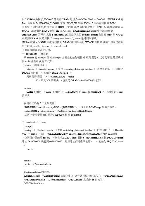
以S3C6410为例子,S3C6410的内部SRAM地址为0x0C00 0000 ~ 0x0C00 1FFF,DRAM的Base地址为0x50000000 ,S3C6410支持NAND,SD启动,S3C6410里面有固化的ROM,当系统上电的时候,将执行固化ROM中的代码,然后检查硬件的GPIO配置,如果配置成NAND 启动,则把NAND的前8K读入内部的SRAM(stepping Stone)中,然后跳转到Stepping Stone的开头,执行Bootloader1 (也就是下文的stepldr), stepldr负责把eboot从NAND 中搬到DRAM中,然后执行eboot( boot loader 2),eboot通过网络下载NK.bin或者从NAND中把内核搬到DRAM中,然后执行WINCE内核.所以整个启动过程分为三阶段,stepldr -->eboot --> wince kernel .下面详细地分析各个阶段.一bootloader 1 stepldr从stepldr的startup.s开始.startup.s主要是初始化硬件,中断,配置好C运行的环境,然后跳转到main函数中,执行C代码.startuo.s 的流程是:startup --> Enable I cache -->关闭watchdog ,Interrupt dosable -> 时钟初始化--> 初始化DRAM控制器--> 初始化IRQ,SVC stack -->判断是否睡眠---N--> Clear DRAM -->main--Y-> 跳到NK的开头(也就是DRAM + 0x100000的地方)main.c :UART初始化--> nand 初始化-> 从NAND中把eboot搬到DRAM中-->跳转到eboot 的开头我们看代码有2个全局变量。
USB设备应用开发套件 для Windows Embedded CE 6.0 用户指南说明书
USB Device Application Kit for WindowsEmbedded CE 6.0User's ManualDigi document reference number: 90000926_A© Digi International Inc. 2008. All Rights Reserved.The Digi logo is a registered trademark of Digi International, Inc.All other trademarks mentioned in this document are the property of their respective owners. Information in this document is subject to change without notice and does not represent a commitment on the part of Digi International.Digi provides this document “as is,” without warranty of any kind, expressed or implied, including, but not limited to, the implied warranties of fitness or merchantability for a particular purpose. Digi may make improvements and/or changes in this manual or in the product(s) and/or the program(s) described in this manual at any time.This product could include technical inaccuracies or typographical errors. Changes are periodically made to the information herein; these changes may be incorporated in new editions of the publication.Digi International Inc.11001 Bren Road EastMinnetonka, MN 55343 (USA)+1 877 912-3444 or +1 952 912-34442Contents1Introduction (6)1.1Features (6)2Requirements (7)2.1BSP requirements (7)2.2Microsoft Windows® CE OS Configuration (7)3Installation (9)4Integration (10)4.1Integration overview (10)4.2Integration process (10)4.3Driver starts (12)5Using the USB Device functionality (13)5.1Serial USB Function Client (13)5.2Mass Storage USB Function Client (17)6Uninstallation (18)3USB Device Application Kit for Windows Embedded CE 6.0 - User's Manual4Conventions used in this manualHere is a list of the typographical conventions used in this manual:StyleNew terms and variables in commands, code, and other input. Style In examples, to show the contents of files, the output fromcommands. In, text the C code.Variables to be replaced with actual values are shown in italics.Style For menu items, dialogs, tabs, buttons, and other controls.In examples, to show the text that you enterMenu name > optionA menu followed by one or more options; for example, File >New.This manual also uses these frames and symbols:This is a warning. It helps solve or avoid common mistakes or problems.This is a hint. It contains useful information about a topic.> This is a host computer session> Bold text indicates what must be entered .> This is a target session > Bold text indicates what must be entered .USB Device Application Kit for Windows Embedded CE 6.0 - User's Manual5AbbreviationsASCIIAmerican Standard Code for Information Interchange CPUCentral Processing Unit ESD Electrostatic DischargeGPIO General Purpose Input/Output OS Operating SystemPC PersonalComputer RAMRandom Access Memory ROOTFSRoot File System TFTPTrivial File Transfer Protocol TTY TeletypewriterUSBUniversal Serial BusUSB Device Application Kit for Windows Embedded CE 6.0 - User's Manual1IntroductionThe USB Device Application Kit is a product that brings the USB Device physical interface to your Digi Development board or JumpStart board.The USB Device Application Kit hardware board connects to the Development or JumpStart board via the USB Application Header and the provided 16-pin flat cable. It basically mounts a USBPHY and USB B female connector.The USB Device Application Kit software contains the driver needed to support the USB DeviceController in a Microsoft Windows® Embedded CE 6.0 OS Design.This User's Manual assumes that the reader is able to create, compile and download a kernel image.1.1FeaturesThe following are the main features of the USB Device Application Kit:•USB 2.0 Full Speed (Low speed not supported)•Board is powered from Development or JumpStart board•Operation modes: serial and mass storage,•±15kV ESD protection6USB Device Application Kit for Windows Embedded CE 6.0 - User's Manual2RequirementsHost System requirementsThe development system has to meet the following requirements:•x86 PC with 500 MHz Pentium III or faster processor; 2 GHz Pentium 4 or equivalent recommended•Microsoft Windows® 2000 Professional with Service Pack 4 or Windows XP Professional with Service Pack 1.•Microsoft Windows® CE 6.0 with Service Pack 1 installed and updates•Serial port•Ethernet network card2.1BSP requirementsDisplay interface support recommended for development purposes, but not required.2.2Microsoft Windows® CE OS Configuration2.2.1Required componentsGo to the Catalog and expand Device Drivers > USB Function > USB Function Clients.Then include this element:USB Function Clients:• Mass Storage• serialWhen using ActiveSync the components from Core OS > CEBASE > Applications – EndUser > ActiveSync must be included into the Windows CE project.Then include this element:ActiveSync:• File SyncFurthermore, the component from Core OS > CEBASE > Communication Services andNetworking > Networking – Wide area Network (WAN) must be included into the Windows CE projectThen include this element:Telephony API (TAPI 2.0):•Unimodem Support7USB Device Application Kit for Windows Embedded CE 6.0 - User's Manual2.2.2Recommended catalog componentsOther recommended networking utilities and services are:Core OS > CEBASE > Communication Services and Networking: • Networking Generalo Network Utilities• Serverso FTP Servero Telnet Server8USB Device Application Kit for Windows Embedded CE 6.0 - User's Manual93 InstallationThis release is installed by executing Setup.exe.The installer wizard will guide you in all required steps.After installation has finished, the following components will be on your PC:%ProgramFiles%\Digi\AppKits\USB_Device_AppKit :• Uninstaller : Executable to uninstall this release.• Release Notes and License Agreements.%_WINCEROOT%\OTHERS\Digi\AppKits\USBFN\src\driver:• Sources of the driver.%ProgramFiles% is an environment variable of your system that provides the path to your Program Files directory (usually C:\Program Files)%_WINCEROOT% is an environment variable of your system that provides thepath to your Microsoft Windows® CE root directory (usually C:\WINCE600).USB Device Application Kit for Windows Embedded CE 6.0 - User's Manual4Integration4.1Integration overviewThe USB Device Application Kit integration described in this chapter assumes that you havealready performed the following steps. These steps are fairly general as they are highly dependant on the customer BSP and the Microsoft Windows® CE version used:Before completing these steps, you will need to have the following applications already installed: •Windows Embedded as described in Chapter 2, and• a BSP corresponding with the hardware that will be used.4.2Integration processThe source code of the driver is also available and can be integrated into a Windows Embedded CE6.0 project as a subproject of it.After you have completely built your Project,it’s time to add a new subproject for theUSB_Device_AppKit Module.Open the Solution Explorer and right-click over the Subprojects. Choose Add ExistingSubproject:Navigate to %_WINCEROOT%\OTHERS\Digi\AppKits\USBFN\src\driver directory and select USBFN.pbpxml:10Now you can see the parameter files and the source files.Right click over USBFN and select Rebuild and then right click over the project and select Make Run-Time Image.The driver build should be rebuilt and included in the final nk.bin image, together with the necessary registry entries.4.3Driver startsVerify that the ns9360_usbfn.dll is inside the new image and that the correct registry entries are placed in the final registry file (reginit.ini).Once the project has been built, download it to the target device and start it up.If you have the USB Device Application Kit connected to the peripheral application header of the target, it should be automatically detected, and you should see a console message similar to thefollowing:[UfnPdd_Init]: Loading USB Device Driver… OK.More information may be shown depending on the debug level established in thedriver.In the console an error message will show up telling that an IOCTL isn’tsupported by the driver. That message can be ignored because that IOCTL onlyreceives some interface information that are not important to the functionality ofthe driver5Using the USB Device functionalityThe USB Device driver provides the functionality upon which the USB function client driverswork. The USB function client drivers implement one or more "functions", each providing adifferent capability to the USB host. In this document we'll see two of these function client drivers: •Serial USB Function Client•Mass Storage USB Function Client5.1Serial USB Function ClientFor both serial profiles standard serial support is necessary within the Windows CE image. Thatcomponent can be found at Core OS > CEBASE > Core OS Services > Serial PortSupport.5.1.1Selecting the ActiveSync profileMake the following change in your USBFN.reg file, you need to uncomment the Serial_Class and comment the rest (“;”).[HKEY_LOCAL_MACHINE\Drivers\USB\FunctionDrivers];"DefaultClientDriver"="Mass_Storage_Class""DefaultClientDriver"="Serial_Class";"DefaultClientDriver"="USBSER_Class"Now you can build the project with the profile selected.Right click over USB_Device_AppKit and select Rebuild and then right click over the project and select Make Run-Time Image.5.1.2Using the profile for ActiveSyncOn the PC side (Host) ActiveSync 4.x or higher must have been installed previously.To use ActiveSync some additional components are necessary. Refer to chapter2.2.1 and include the listed components.If the components have been includedafter building the project a SYSGEN must be done again.After building and deploying successfully the Windows CE image a ActiveSync connection might be necessary to be created on the target side. This is only necessary if more than one serial port is enabled on the target device.Following the steps that are necessary to create on the target side a new direct connection that can be used later by ActiveSync.From the Start menu select Settings -> Network and Dial-up Connections and create a new Direct Connection selecting the Make New Connection option. Select on the next page the serial port that was setup by the system for the USB function interface and close the dialog. The information on the following picture is only an example and that value might be different on other platforms.Now the new connection to use the USB function driver is created. The next step is to use that connection as the default configuration for ActiveSync. Select from the Start menu Settings -> Control Panel and open the PC connection item.Click on the Change button and select the new created direct connection from the list of available connections. Confirm both dialogs with OK and now when connecting the USB function device to the PC ActiveSync should automatically start.5.1.3Selecting the Serial profileMake the following change in your USBFN.reg file, you need to uncomment the Serial_Class and comment the rest (“;”).[HKEY_LOCAL_MACHINE\Drivers\USB\FunctionDrivers];"DefaultClientDriver"="Mass_Storage_Class";"DefaultClientDriver"="Serial_Class""DefaultClientDriver"="USBSER_Class"Now you can build the project with the profile selected.Right click over USB_Device_AppKit and select Rebuild and then right click over the project and select Make Run-Time Image.5.1.4Using the Serial profileWhen using the serial profile no additional components are necessary to expose a serial port to the Host.On the PC side (Host) the standard USB serial driver (usbser.sys) need to be installed. Afterbuilding and deploying successfully the Windows CE image connect the USB cable with the device connector to the target and with the host connector to a PC or Laptop. The first time the host willinstall the corresponding driver and the device will be available for use. In the Device Manager the COM number assigned to the serial port can be found and normal serial communication can beused between the target and the connected PC.5.1.5Installing the USB Serial driver under WindowsIn case the USB serial driver isn’t installed on the used Windows machine the usbser.sys file comes with various versions of Windows. It can be found on Windows XP typically inC:\WINDOWS\Driver Cache\i386\driver.cabWhen the generic serial driver is loaded and the USB device connected to the Windows host with a USB cable, Windows should recognize the generic serial device and ask for a driver. IndicateWindows to find the driver in the folder that contains usbser.inf and usbser.sy s.The usbser.inf is included in the Kit as an example and can be found atC:\Program Files\Digi\AppKits\USB_Device_AppKit\infOn Windows XP, when the generic serial device is first plugged in, the "Found New HardwareWizard" starts up. Select "Install from a list or specific location (Advanced)", on the next screen select "Include this location in the search" and enter the path or browse to the folder containingusbser.inf and usbser.sys.Windows will complain that the Generic Serial driver has not passed Windows Logo testing, but select "Continue anyway" and finish the driver installation. In the "Device Manager" (under"Control Panel", "System", "Hardware") on Windows XP expand the "Ports (COM & LPT)" entry and you should see Generic Serial Port listed as the driver for one of the COM ports.5.1.6Uninstalling the USB Serial driver under WindowsTo uninstall the Windows XP driver for Generic Serial Port, right click on the Generic Serial Port entry in the "Device Manager" and select "Uninstall".5.2Mass Storage USB Function Client5.2.1Selecting the profileMake the following change in your USBFN.reg file that is part of the subproject, you need to uncomment the Mass_Storage_Class and comment the rest (“;”).[HKEY_LOCAL_MACHINE\Drivers\USB\FunctionDrivers]"DefaultClientDriver"="Mass_Storage_Class";"DefaultClientDriver"="Serial_Class";"DefaultClientDriver"="USBSER_Class"Now you can build the project with the profile selected.Right click over USB_Device_AppKit and select Rebuild and then right click over the project and select Make Run-Time Image.5.2.2Using the profileTo use the Mass Storage profile a block device like CF, SD card or USB Memory stick is necessary to make the profile working correctly. Following some examples how some of these block devices need to be added to the Windows CE project.Exposing a USB memory stick from the target to a PC (Host) the components USB Mass Storage Function client, USB Host support and USB Storage class driver are necessary. Using any otherWhen connecting the USB cable to the Host it might take some time till thestorage device is represented .6UninstallationThe USB Device Application Kit can be uninstalled separately using Windows Control Panel.Add or Remove Programs:•USB Device Application Kit for Windows Embedded CE 6.0。
06- Tiny6410 WindowsCE开发指南
copyright@2010更新说明:3.3.5创建SDK .................................................................................................................................... - 90 -Nand Flash启动系统,系统启动时的画面如图(请以实物为准)。
触摸屏校正缺省安装的wince系统的触摸屏校正参数一般适用于NEC 4.3”LCD屏的物理特性不同,有时可能不太准确,特别是不同尺寸的时候,这时就需要重新校正,如根据系统提示,使用五点校正法用触摸笔开始校正,校正完毕,将会跳出如下窗口,这时随便点一个位置即可返回“笔针属性”窗口,点“OK”保存退出。
如果您想保存本次校准的参数,请点“开始->屏幕旋转系统,桌面上有个小画笔的程序:Painter,你可以使用它来测试设置实时时钟并保存用户存储空间使用优盘和SD卡播放mp3测试按键测试PWM控制蜂鸣器录音测试根据提示,点“录音”按钮开始录音,这时对着板上的麦克风说话,程序开始录音,点“停止”按钮结束录音,如图:此时可以点“播放”按钮会循环播放刚才的录音。
说明:该录音程序并不保存录音结果。
的普通串口功能驱动尚不可用,要测试这三个串口,需要请使用交叉串口线连接开发板的点“设置”按钮,打开设置窗口,设置串口号为右上),点确定返回主窗口。
同时,连接好扩展板的COM2到PC一端,并在然后,在串口调试助手的主窗口点“接收”按钮(该按钮会改变为“不接收”端的串口终端输入一些字符(通过超级终端是无法看到的的字符会在开发板串口调试助手的接收区显示,如图:我们还可以使用同样的方法测试硬解码播放器点“文件”->“打开文件”找到SD卡或你自己的其他视频文件,如图选中文件,就可以观看硬解码播放的电影了。
使用注意事项:因为6410最大仅支持720x480的硬解码播放,所以在稍微有点卡,此时可以点“选项”->"缩放“->"100%"和“选项"->"此时把电视输入设置为CVBS,并与目标板之间使用黄色的视频线连接好,上的输出消失,画面转到了TV,如图。
wince6.0编译环境一二三

wince6.0编译环境一二三(转摘)收藏在WinCE5.0中,在"Build OS”菜单中,我们会看到不同的编译选项:"Sysgen","Build and Sysgen"和"Build and Sysgen current BSP"Sysgen:不用多说,当你在"Catalog"中添加或删除了新的item的时候,就用这个吧。
Build and Sysgen:当你更新了\public目录下的源代码的时候,你就需要用这个了。
一般比如在打patch以后,可能就需要进行Build and Sysgen了。
Build and Sysgen current BSP:当你只改变了你的BSP部分的代码,就可以用这个选项。
据说,当你改变了\platform目录下的代码,也可以用这个,具体没有试过。
在WinCE6.0中,在VS2005的"Build"菜单中,有一个“Advanced Build Commands”,其中有很多编译选项:"Sysgen":相当于执行命令"blddemo -q”,一般第一次编译或者是改变了"Catalog"中的item的时候,就用这个了。
"Clean Sysgen":相当于执行命令"blddemo clean -q",按照文档上的说明,当修改了%_WINCEROOT%\Public\CEBASE\OAK\Misc\Cesysgen.bat的时候,或者改变了以SYSGEN,BSP为前缀的环境变量的时候,需要使用这个来编译。
在此我说一下我个人的经验,一般只有第一次创建完工程的时候,我会用"Sysgen"命令,以后只要是改变了SYSGEN为前缀的环境变量的设置或者是"Catalog"中的item,我就会使用"Clean Sysgen",而改变了以BSP为前缀的环境变量要看具体情况,也不一定就要用"Clean Sysgen"。
WinCE 6.0的大容量NAND Flash驱动开发
WinCE 6.0的大容量NAND Flash驱动开发
俞翔;高明煜;何志伟
【期刊名称】《杭州电子科技大学学报》
【年(卷),期】2009(029)001
【摘要】该文阐述了一种基于Windows CE 6.0的车载全球定位导航器内大容量NAND Flash驱动程序开发.介绍了Marvell公司的PXA310嵌入式处理器与三星公司NAND Flash存储器的硬件连接方式,详细分析了WinCE6.0下NAND Flash 驱动程序结构,为增强代码可移植性,设计了FMD分层模型,同时解决了WinCE内核空间和用户空间在同一块大容量Flash上的共享问题.经实验证明,所设计的大容量闪存驱动程序能够可靠运行,达到了预期目标.
【总页数】4页(P13-16)
【作者】俞翔;高明煜;何志伟
【作者单位】杭州电子科技大学系统集成研究所,浙江,杭州,310018;杭州电子科技大学系统集成研究所,浙江,杭州,310018;杭州电子科技大学系统集成研究所,浙江,杭州,310018
【正文语种】中文
【中图分类】TN392
【相关文献】
1.Nand Flash的驱动开发及产品化探讨 [J], 郭鑫俊;
2.WinCE系统上大容量NAND Flash驱动设计与优化 [J], 张超;张哲;胡晨
3.Nand Flash的驱动开发及产品化探讨 [J], 郭鑫俊
4.NandFLASH和NorFLASH接口设计和驱动开发 [J], 赵军伟;李宏穆;庄阿龙;何剑锋
5.WinCE
6.0下双模终端的USB转串口驱动开发 [J], 张旭;何维;田增山
因版权原因,仅展示原文概要,查看原文内容请购买。
基于WINCE6.0+S3C6410的背光驱动

基于WINCE6.0+S3C6410的背光驱动1.硬件电路设计基于PWM来调整背光亮度的硬件设计电路如下图所示:图12.基于PWM的控制原理我们使用S3C6410的定时器1来输出PWM信号来调整背光亮度,见PWM定时器部分的描述图23.软件实现3.1定时器1的时钟值的确定1)PCLK本设计中采用ARM主频为533MHZ,HCLK=133MHZ,PCLK=66MHZ,至于这个值的确定见时钟控制器部分。
2)PCLK时钟的第一级分频值见图2的描述,也就是8位Prescaler 0的值的确定,见相关寄存器TCFG0的描述图3代码中的实现如下:图4图4中,我们选择定时器1的Prescaler 0的值为0x3,根据给出的公式:图5这样算出PCLK始终经过第一级分频之后的时钟频率为66MHZ/(3+1)=16.5MHZ。
3)PCLK时钟的第二级分频值见图2的描述,可知每个定制器都有自己的时钟分割器,分频值为1/1、1/2、1/4、1/8、1/16或者是TCLK0作为定时器1的时钟源,图4中,我们选择的是1/8的分频系数,见相关寄存器TCFG1的描述图6结合图5,这样我们就可以算出定时器的时钟频率为16.5 MHZ/8=2.0625MHZ,同时可以算出定时器时钟周期为=0.4848us。
3.2定时器控制寄存器TCON的自动重新装载位和手动更新位下图是TCON寄存器中的相关描述图7在代码中的内容见图4,下面大概描述这两位的作用:1)自动重新装载位当定时器1的下降寄存器的值下降到0的时候,只有使能了自动重新装载位,也即置1,TCNTB1寄存器的值才能自动重新装载到下降寄存器中,从而开始下个周期,才能输出周期新的PWM信号。
2)手动更新位只有手动更新位置1的时候,TCNTB1和TCMPB1的值才会装载到TCNT1和TCMP1,也即下降寄存器和比较寄存器中。
但是在我们开启定时器的时候,需要对手动更新位清零,否则不会有PWM周期信号输出。
WINCE6.0+S3C6410串口驱动
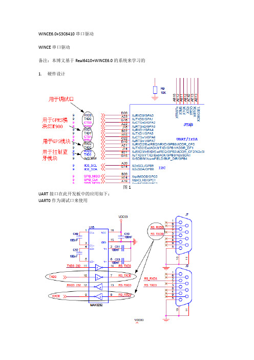
WINCE6.0+S3C6410串口驱动WINCE串口驱动备注:本博文基于Real6410+WINCE6.0的系统来学习的1. 硬件设计图1 UART接口在此开发板中的应用如下:UART0作为调试口来使用图2 UART1用于和GPRS模块SIM900通信图3 UART2用于和GPS模块COMPASS_EB818通信图4UATR3用于和蓝牙模块通信图52. 软件设计2.1 WINCE串口驱动的架构在WINCE系统中,串口驱动是作为一个流驱动的形式存在,其驱动架构如下图所示:图6串口驱动分为MDD层和PDD层,DD层对上层的Device Manager(device.dll)提供了标准的流设备驱动接口(COM_xxx),PDD层实现了HWOBJ结构及结构中若干针对于串口硬件操作的函数指针,这些函数指针将指向PDD层中的串口操作函数。
DDSI是指MDD层与PDD层的接口,在串口驱动中实际上就是指HWOBJ,PDD层会传给MDD层一个HWOBJ结构的指针,这样MDD层就可以调用PDD层的函数来操作串口。
2.2 MDD层的导出接口函数MDD层为系统提供流设备接口,这些接口微软已经实现,但还是有必要学习一下2.2.1 COM_Init此函数始化串口设备,该函数通过读取注册表获得串口设备号,并获得相应的HWOBJ的结构指针,通过该指针调用PDD层的硬件初始化函数初始化串口。
Identifier:如果驱动被设备管理器加载,那么这个参数将包含一个注册表键值在”HKEY_LOCAL_MACHINE\Drivers\Active”路径下。
如果驱动是通过调用RegisterDevice函数来加载的,那么这个值等于dwInfo的值。
在COM_Init中,会先打开该键值,用返回的句柄来查询DeviceArrayIndex值,并根据该值获得PDD层的HWOBJ结构指针,下图是COM_Init函数的一部分图72.2.2 COM_Deinit卸载串口设备,该函数中主要做了一些释放资源的操作。
- 1、下载文档前请自行甄别文档内容的完整性,平台不提供额外的编辑、内容补充、找答案等附加服务。
- 2、"仅部分预览"的文档,不可在线预览部分如存在完整性等问题,可反馈申请退款(可完整预览的文档不适用该条件!)。
- 3、如文档侵犯您的权益,请联系客服反馈,我们会尽快为您处理(人工客服工作时间:9:00-18:30)。
EZ6410 WinCE 6.0 Driver Guide深圳市优龙科技有限公司Revision HistoryRevision No Description Change Refer to Author(s)Datedraft--- czx 2009-7-28 V1.0 PreliminaryContents1BOOT MEDIA CONFIGURATION (4)1.1NOR F LASH B OOT (4)1.2NAND F LASH B OOT (4)1.3I NTERNAL ROM–SD/MMC B OOT (4)2OAL OPTION CONFIGURATION (6)2.1S YSTEM C LOCK C ONFIGURATION (6)2.2LCD D ISPLAY M ODULE C ONFIGURATION (7)2.3UART D EBUG P ORT C ONFIGURATION (8)2.4NAND F LASH (9)3DISPLAY DRIVER CONFIGURATION (9)4TOUCH SCREEN DRIVER CONFIGURATION (10)5KEYPAD DRIVER CONFIGURATION (11)6POWER BUTTON DRIVER CONFIGURATION (12)7AUDIO DRIVER CONFIGURATION (12)8CAMERA DRIVER CONFIGURATION (13)9I2C DRIVER CONFIGURATION (13)10SPI DRIVER CONFIGURATION (14)11USB DRIVER CONFIGURATION (14)11.1USB D EVICE (14)11.1.1Serial Function Driver (15)11.1.2Mass Storage Function Driver (15)11.2USB H OST (15)12SERIAL DRIVER CONFIGURATION (16)12.1UART (16)12.2I R DA (17)12.3A CTIVE S YNC (17)13SD / HSMMC DRIVER CONFIGURATION (18)14HIVE-BASED REGISTRY (18)15MULTIPLE XIP (19)16WLAN CONFIGURATION (21)16.1RT2870 (21)17NETWORK DRIVER CONFIGURATION (21)18GPIO DRIVER CONFIGURATION (22)1 Boot Media ConfigurationIt is available to boot through both NAND Flash and AMD Flash (NOR Flash) in the EZ6410 Board.This information is applied to YL6410_CPU_V1.1 Board and EZ6410_DEV_V1.2.1.1 NOR Flash BootIn YL6410_CPU_V1.1 Borad.SW1SW21 2 3 41 2 3 4 ON ON OFFONOFFONONON/OFF1.2 NAND Flash BootNAND TYPE:1. K9F2G08U0A(256MB,SLC)2. K9G8G08U0M(1GB,MLC)In YL6410_CPU_V1.1 Borad.SW1SW21 2 3 41 2 3 4 ON ON ONOFFOFFONONON/OFF1.3 Internal ROM – SD/MMC BootOnly the FMD BSP support iROM BootIn YL6410_CPU_V1.1 BoardSW1 SW21 2 3 4 1 2 3 4 ON ON ON ON ON ON ON ON/OFFR83 R84 R85 R86 R87 R88SD/MMC Channel 0 Boot NC NC NC 10K 10K 10KTo make an image that can boot up using Internal ROM, you should do the followings:SD/MMC Channel 0:Remark: The EZ6410 board default setting is boot form NAND FLASH.2OAL option configuration2.1System Clock Configuration- You can change System Clock Speed (including CPU Clock)- There are three pre-defined values for control system clock speed1.PLATFORM\COMMON\SRC\SOC\S3C6410_SEC_V1\OAL\INC\soc_cfg.2.PLATFORM\COMMON\SRC\SOC\S3C6410_SEC_V1\OAL\INC\s3c6410. - Default setting is 666Mhz/133Mhz/66.5Mhz. (ARM/HCLK/PCLK)2.2LCD Display Module Configuration- You can change LCD module type for SMDK6410 board- There are ten LCD modules configuration in BSPLTS222 :Portrait 2.2" QVGA RGB16LTV350 :Landscape 3.5" QVGA RGB16LTE480 :Landscape 4.8" WVGA RGB16EMUL48_D1 :Landscape 4.8" WVGA RGB16 as D1 (720x480)EMUL48_QV :Landscape 4.8" WVGA RGB16 as QVGA (320x240)EMUL48_PQV :Landscape 4.8" WVGA RGB16 as PQVGA (240x320)EMUL48_ML :Landscape 4.8" WVGA RGB16 as 480x320EMUL48_MP :Landscape 4.8" WVGA RGB16 as 320x480LTP700 :Landscape 7" WVGA RGB24LTM030DK :Portrait 3.5" WVGA RGB16DH320 :东华3.5" 320x240 RGB16AT080TN52 :群创8" 800x600 RGB16AT070TN83 :群创7" 800x480 RGB16VGA :General VGA Display (800x600) RGB16- Default setting is AT070TN83 (800x480).- If you want use any other module than pre-defined in BSP, you should define several definitions related to LCD module dimensions as sample code in bsp_cfg.h, and implement LDI_fill_output_device_information() function and modulecontrolfunctions(LDI_XXX())in \smdk6410\SRC\drivers\Display\s3c6410_disp_ldi.c file2.3UART Debug Port Configuration- There are two UART port available for debug. You can use one port at a time.- If you set BSP_DEBUGPORT as following code, Debug port will use UART0- Default setting is UART0- You can change Baudrate for debug port also- Default setting is 115200 bps- You should configure the baudrate of terminal program in your host PC same as YL6410 Board.2.4NAND Flash- For using NAND Flash, timing parameter should be set appropriately- The default setting leaves a margin. (TACLS: 7, TWRPH0: 7, TWRPH1: 7)- Please set optimal timing parameter for NAND Flash your platform uses3Display Driver Configuration- Display Driver Configuration- If you clear BSP_NODISPLAY as following code, Display driver will be included in OS image- Default setting is enabled.- Setting BSP_NODISPLAY=1 means that display driver is removed from OS image.4 Touch Screen Driver Configuration- Touch screen device can be disabled. (set BSP_NOTOUCH=1)- If you clear BSP_NOTOUCH as following code, Touch screen driver will be included in OS image - Default setting is enabled.- Setting BSP_NOTOUCH=1 means that touch screen driver is removed from OS image.-After Changing, Build display driver and make image.- Default calibration data is defined in registry. Set proper value for the touch panel you have.5Keypad Driver Configuration- Keypad/Keyboard device can be disabled. (set BSP_NOKEYBD=1)- If you clear BSP_NOKEYBD as following code, Keypad/Keyboard driver will be included in OS image- Default setting is enabled.- Setting BSP_NOKEYBD=1 means that keypad/keyboard driver is removed from OS image.- After Changing, Build keypad/keyboard driver and make image.- You can change K1~K8 keys function.6 Power Button Driver Configuration- You can enter sleep mode and trigger S/W reset with power button driver - Power Button is S3 (S3 in bottom of YL6410_DEV_V1.2 board) - Reset Button is S1 (S1 in bottom of YL6410_DEV_V1.2 board) - Power Button driver can be disabled. (set BSP_NOPWRBTN=1)- If you clear BSP_NOPWRBTN as following code, Power Button driver will be included in OS image - Default setting is disabled.- Setting BSP_NOPWRBTN=1 means that Power Button driver is removed from OS image.- After Changing, Build Power driver and make image7Audio Driver Configuration-YL6410 only supports AC97 interfaces- Audio driver can be disabled (set BSP_NOAUDIO=1) - Default setting is enabled and AC97 interface8 Camera Driver Configuration- Camera type is OV9655(130Mega pixels)-Camera driver can be disabled. (set BSP_NOCAMERA=1)- Default setting is enabled.- If you clear BSP_NOCAMERA as following code, Camera driver will beincluded in OS image-Setting BSP_NOCAMERAI=1 means that Camera driver is removed from OS image. - After Changing, Build Camera driver and make image-Because Camera driver use I2C interface to control external camera module. You have to include I2C driver in OS image9I2C Driver Configuration- I2C driver can be disabled. (set BSP_NOI2C=1) - Default setting is enabled.- If you clear BSP_NOI2C as following code, I2C driver will be included in OS image - Setting BSP_NOI2C=1 means that I2C driver is removed from OS image. -After Changing, Build I2C driver and make image10 SPI Driver Configuration- SPI driver can be disabled. (set BSP_NOSPI=1) - Default setting is enabled.-If you clear BSP_NOSPI as following code, SPI driver will be included in OSimage- Setting BSP_NOSPI=1 means that SPI driver is removed from OS image. - After Changing, Build SPI driver and make image11USB Driver Configuration 11.1 USB Device- USB device can be disabled. (set BSP_NOUSBFN=1) - Default setting is enabled and Serial function.- If you clear BSP_NOUSBFN as following code, USB device driver will be included in OS image- Setting BSP_NOUSBFN=1 means that USB device driver is removed from OS image.- After Changing, Build display driver and make image. - You can not use USB function device and USB KITL at a time.11.1.1Serial Function Driver- You can use USB Serial Function driver by setting as follows.- Default setting is serial function driver- After changing, Build USB function driver and make image.11.1.2Mass Storage Function Driver- You can use USB Mass Storage Function driver by setting as follows.- After changing, Build USB function driver and make image.11.2USB Host- USB device can be disabled. (set BSP_NOUSBHCD=1)- Default setting is enabled.- If you clear BSP_NOUSBHCD as following code, USB Host driver will be included in OS image- Setting BSP_NOUSBHCD=1 means that USB Host driver is removed from OS image.- After Changing, Build USB Host driver and make image.12Serial Driver Configuration- All serial drivers can be disabled. (set BSP_NOSERIAL=1)- Default setting is enabled.- So if you want to enable serial driver, clear BSP_NOSERIAL-Setting BSP_ NOSERIAL =1 means that Serial driver is removed from OS image.12.1UART- UART0, UART1, UART2 and UART3 can be disabled by each setting in BSP.- Default BSP setting is enabled UART1 and UART2.- The following codes means enable UART1 and UART2.- After Changing, Build driver and make image.- The following codes means enable UART0- Be careful when using UART0 as general purpose COM port. UART0 is default debug port. You must change debug port to UART1.- You can change debug port to UART1 like the following. Then you can use UART0 as COM port without conflict- After Changing, Build driver and make image.- In YL6410 board, UART2 and UART3 share same J3 port.12.2IrDA- IrDA uses UART2, UART3- Default BSP setting IrDA on UART3 is enabled.- If you want to use IrDA on UART channel2, set like the following.- Be careful When using UART Channel 2 as IrDA, you cannot use UART channel2 as UART. So, Do not Enable IrDA2 and UART2 at the same time.- If you clear BSP_NOIRDA2 like following code, you can use IrDA device.- After Changing, Build driver and make image.- And you need EZ6410_DEV_V1.1 board setting.- No short the jumper JP1 on EZ6410_DEV_V1.1 Board.- If you want to use IrDA on UART channel3, set like the following.- And you need YL6410_DEV_V1.2 board setting.- Short the jumper JP1 on YL6410_DEV_V1.2 Board.12.3Active SyncNONE13SD / HSMMC Driver Configuration- The driver supporting 4 bit DAT bus width on SD/HSMMC Channel 0 can be disable, Default setting is enabled.■set BSP_NOHSMMC_CH0=- The drivers supporting 4 bit DAT bus width on SD/HSMMC Channel 1 can be disabled, Default setting is enabled.■set BSP_NOHSMMC_CH1=- Driver Supporting 8 bit DAT bus width on Channel 1 can be enabled, Default setting is disabled.■set BSP_HSMMC_CH1_8BIT=- If you clear BSP_NOHSMMC_CHx as following code, SD/HSMMC drivers will be included in OS image. (Channel 0 is 4 bit, Channel 1 is 4 bit.)- After Changing, Build driver and make image.14Hive-Based RegistryYou can implement that hive files are stored to NandFlash. By default, RAM-based registry is used in the BSP. For implementing hive-based registry, set it as follows.- Add the Hive-based Registry Catalog item to your OS design.- And then set configuration like following code- After changing, rebuild solution for clean build. Without clean build, Hive-registry properties may be not included in OS image.15Multiple XIPOur BSP support Multiple XIP on NAND flash media by BinFS. The Hive-Based registry is required when using BINFS(demand-paged, pseudo-multi-XIP) because all of the file system waiting/blocking is implemented in the hive-based registry init code, and not in the RAM-Based registry init code.- Single .bin: Nk.bin fileThe run time image is single image and is loaded to RAM in booting time.- Multiple .bin(for demand paging): xipkernel.bin, nk.bin and chain.bin The XIPKERNEL region is where files that must be loaded prior to BinFs are stored. The NKregion is the location for files not stored in the XIPKERNEL region. The CHAIN region is usedby the bootloader to access information on where each region is located.- By default, Multiple-XIP images are no used.- Hive-registry must be used for multiple-XIP images.- The XIPKERNEL region files must include nk.exe, nandflash.dll, kitl.dll, kernel.dll, kd.dll, hd.dll, osaxst0.dll, osaxst1.dll, coredll.dll, oalioctl.dll, k.coredll.dll, fpcrt.dll, k.fpcrt.dll, filesys.dll, romfsd.dll, device.dll, udevice.dll, devmgr.dll, regenum.dll, busenum.dll, pm.dll, servicesEnum.dll, servicesd.exe, services.exe, serviceStar.exe, zlib.dll, softkb.dll, binfs.dll, fsdmgr.dll, mspart.dll, ceddk.dll, wince.nls and boot.hv.- To make the XIPKERNEL as small as possible, XIPKERNEL should have above files only – as a minimum set of files which are required to boot and initialize the BINFS.- The MultipleXIP.bib file is included in the config.bib to apply the above list intoce.bib on “makeimg” process. The including code is like as follows:- All driver which has Powerdown/PowerUp function must be made in non-pageable for power handler scheme in WinCE6.0. You can find all drivers that need to be non-pageable with below command.flatreleasedir> findstr /m “PowerDown” *.map- After searching such as those drivers with above command, you must make them be non-pageable with adding ‘M’flag in the .bib file.16 WLAN Configuration- Our BSP support WLAN driver.- Default setting is enabled.16.1 RT2870-WLAN module is RT2870 (USB 2.0 interface) - RT2870 support 802.11 b/g.- Default setting is enabled.- We supply WLAN Driver is binary format(.dll).- After Changing, make image.17 NETWORK Driver Configuration- The driver support 10Mbps network- Default setting is enabled.- After Changing, Build driver and make image.18GPIO Driver Configuration- The driver support all gpio.- Default setting is enabled.- After Changing, Build driver and make image.。
