Quincy QGD37~160 操作手册
迪伦斯(Quanser Inc.)NI ELVIS RIO控制模块设置与配置指南说明书
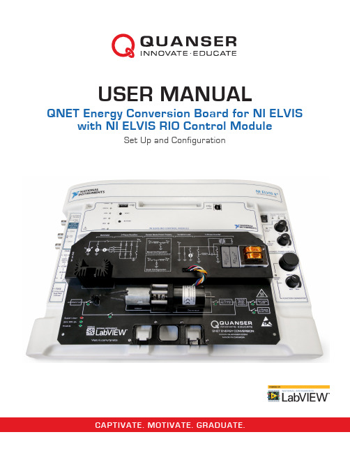
CAPTIVATE. MOTIVATE. GRADUATE.USER MANUALQNET Energy Conversion Board for NI ELVISwith NI ELVIS RIO Control ModuleSet Up and Configuration©2016Quanser Inc.,All rights reserved.Quanser Inc.119Spy CourtMarkham,OntarioL3R5H6,Canada****************Phone:1-905-940-3575Fax:1-905-940-3576For more information on the solutions Quanser Inc.offers,please visit the web site at:This document and the software described in it are provided subject to a license agreement.Neither the software nor this document may be used or copied except as specified under the terms of that license agreement.All rights are reserved and no part may be reproduced,stored in a retrieval system or transmitted in any form or by any means,electronic,mechanical,photocopying,recording,or otherwise,without the prior written permission of Quanser Inc.Japan VCCI Notice This is a Class A product based on the standard of the Voluntary Control Council for Interference(VCCI).If this equipment is used in a domestic environment,radio interference may occur,in which case the user may be required to take corrective actions.Waste Electrical and Electronic Equipment(WEEE)This symbol indicates that waste products must be disposed of separately from municipal household waste,according to Directive2002/96/EC of the European Parliament and the Council on waste electrical and electronic equipment(WEEE).All products at theend of their life cycle must be sent to a WEEE collection and recycling center.Proper WEEE disposal reduces the environmentalimpact and the risk to human health due to potentially hazardous substances used in such equipment.Your cooperation in properWEEE disposal will contribute to the effective usage of natural resources.For information about the available collection andrecycling scheme in a particular country,go to /citizenship/weee.This product meets the essential requirements of applicable European Directives as follows:•2006/95/EC;Low-Voltage Directive(safety)•2004/108/EC;Electromagnetic Compatibility Directive(EMC)Caution:This is a Class A product.This product may cause radio interference in a domestic environment,inwhich case the user may be required to take adequate measures.ContentsSafety Information4 1Introduction5 2System Hardware62.1System Schematic62.2Modes of operation72.3Hardware Components112.4Interfaces132.5Supervisor182.6Environmental193QNET Energy Conversion Setup20 4Troubleshooting224.1You are getting’VI Missing’messages224.2The AC generator motors are not responding22QNET ENERGY CONVERSION-User Manual v1.0Safety InformationThe following symbols and definitions are interchangeably used throughout the User Manual: Symbol DescriptionCaution:consult documentation for additional informationDirect Current|On(Power)[on NI ELVIS II unit]⃝Off(Power)[on NI ELVIS II unit]Table0.1:Symbols1IntroductionThe Quanser QNET Energy Conversion Board for NI ELVIS with ELVIS RIO Control Module is pictured in Figure 1.1.It is a reconfigurable system designed to teach the fundamentals of energy conversion across the electrical and mechanical domains.The modular system supports a number of different configurations and measurements of key parameters are achievable using the resources on the ELVIS RIO.Example experiments include open and closed loop SMPS (switched-mode power supply)control,3-phase power generation,rectification,inverters,and power system integration and applications.The main QNET Energy Conversion features include:•Linear power amplifier•Mechanically coupled motor assembly (3-phase generator)•Rectifier•SMPS with configurable buck or boost topology •Inverter and transformer •Linear currentloadFigure 1.1:Quanser QNET Energy Conversion Board for NI ELVIS with ELVIS RIO ControlModuleCautionThis equipment is designed to be used for educational and research purposes and is not intended for use by the general public.The user is responsible to ensure that the equipment will be used by technically qualified personnel only.QNET ENERGY CONVERSION -User Manual v 1.02System Hardware2.1System SchematicThe QNET Energy Conversion provides an integrated communication interface with the NI ELVIS RIO Control Module.The interaction between the different system components on the QNET Energy Conversion is illustrated in Figure2.1.The NI ELVIS RIO Control Module is interfaced to the PC or laptop via USB link.The NI ELVIS RIO Control Module provides command signals to the QNET Energy Conversion components.An on board supervisor is used to safeguard the hardware and to set the mode of operation.Figure2.1:Interaction between QNET Energy Conversion components2.2Modes of operationThe QNET Energy Conversion may be configured to represent the modes that are outlined below.This is accomplished over a communications interface between the ELVIS RIO and the supervisor.After selecting a mode, the supervisor will automatically connect the appropriate modules on the board.2.2.13-Phase PowerThis mode includes the linear amplifier,as well as the3-phase AC generator components(no rectifier).Figure2.2:Three phase power configuration2.2.2Boost ConverterThis mode includes the linear amplifier,switched mode power supply(in boost)and the variable load components.Figure2.3:Boost converter configuration2.2.3Buck ConverterThis mode includes the linear amplifier,switched mode power supply(in buck)and the variable load components.Figure2.4:Buck converter configurationQNET ENERGY CONVERSION-User Manual v1.02.2.4InverterThis mode includes the linear amplifier and the single phase inverter components.Figure2.5:Inverter configuration2.2.5RectifierThis mode includes the linear amplifier,3-phase AC generator and rectifier components.Figure2.6:Rectifier configuration2.2.6Generator-to-BoostThis mode includes the linear amplifier,3-phase AC generator,rectifier,switched mode power supply(in boost)and variable load components.Figure2.7:Generator to Boost configuration2.2.7Generator-to-Boost-to-InverterThis mode includes the linear amplifier,3-phase AC generator,rectifier,switched mode power supply(in boost)and single phase inverter components.Figure2.8:Generator to boost to inverter configuration2.2.8Generator-to-BuckThis mode includes the linear amplifier,3-phase AC generator,rectifier,switched mode power supply(in buck)and variable load components.Figure2.9:Generator to buck configurationQNET ENERGY CONVERSION-User Manual v1.02.2.9Buck-to-InverterThis mode includes the linear amplifier,switched mode power supply(in buck)and single phase inverter components.Figure2.10:Buck to inverter configuration2.2.10Boost-to-InverterThis mode includes the linear amplifier,switched mode power supply(in boost)and single phase inverter components.Figure2.11:Boost to inverter configuration2.3Hardware ComponentsThe main components comprising the QNET Energy Conversion board are labelled in Figure2.12,and are listed in Table2.1.Table2.1:QNET Energy Conversion component nomenclatureFigure2.12:General layout of QNET Energy ConversionExposed moving parts near the AC-generator assemble.CautionCaution2.3.1Linear AmplifierThe QNET Energy Conversion uses a power op amp to supply either the DC motor or the SMPS,depending on the mode of operation.It has a voltage compliance of0to20V.2.3.23-phase AC Generator and RectifierThe QNET Energy Conversion uses the Anaheim Automation BLWR11D-24V-10000brushless DC Motor as a 3-phase AC Generator.The specification sheet can be found at:Anaheim Automation BLWR11D-24V-10000.The generator is driven using a Micro-drives M2232U-24-GS-050brushed DC Motor.The specification sheet can be found at:Micro-drives M2232U-24-GS-050.The rectifier can be dynamically configured for3-phase or single phase operation with or without bulk capacitors of 1µF and10µF.2.3.3Switched Mode Power SupplyThe switched mode power supply can be configured as a buck or a boost.A maximum switching frequency of 25MHz is enforced for both topologies.The boost configuration is limited to a duty cycle range of0to50%and an On-time of150µs.The maximum boost output voltage is30V.2.3.4Variable LoadThe variable load on the QNET Energy Conversion board is a current sink.It is capable of sinking250mA or more, given a source above7V with a low output impedance.Attempting to command loads in excess of250mA will cause the load to saturate near300mA.2.3.51-Phase InverterThis includes an isolated step down power transformer to a resistor load.The maximum input voltage is30V,which is the maximum output from the switch mode power supply.The inverter needs a minimum voltage of10.5V tooperate.Once enabled,a minimum input voltage of8.5V must be maintained.2.4Interfaces2.4.1Control SPI InterfaceThis SPI interface operates with16-bit data at5MHz or lower,with CPOL=0(clock polarity)and CPHA=0(clock phase).Data is transmitted MSb(most significant bit)first.The NI ELVIS RIO Control Module acts as a master.This interface is used to set the board mode,clear the watchdog and set the values of user controlled switches.The pin definitions are defined in Table2.2.Table2.2:Control SPI Interface pin definitionsThe data input contains the raw supervisor code,as described above,as well as a board ready bit as shown in Figure2.13a.The board ready bit is set after the board is ready to be used after changing the mode from reset.The board ready bit is cleared after the board is put into reset or if it enters the supervisor state.(a)Input Data format(b)Output Data formatFigure2.13:Control SPI16-bit data configurationThe data output is split into two bytes.The upper byte is a preamble and the interpretation of the lower byte depends on the value in the preamble.The format is as shown in Figure2.13b.The preamble and lower byte behavior are as described in Table2.3.Table2.3:Preamble and lower byte behavior2.4.2Inverter SPI InterfaceThis interface is reserved exclusively for commanding the inverter voltage.The pin definitions are as described in Table2.4.Table2.4:Inverter SPI Interface pin definitionsThis interface only contains data output.The inverter voltage command is signed and corresponds to the percentage of the amplitude being commanded to the inverter driver.For example-1024commands the maximum negative voltage and1023commands the maximum positive voltage.This uses the2’s complement via11bits,as shown in Figure2.14Figure2.14:Inverter SPI16-bit data configuration2.4.3I/O channelsThe outputs are defined in Table2.5.The inputs are defined in Table2.6.Table2.5:Output pins defined in the custom FPGA codeTable2.6:Input pins defined in the custom FPGA code2.5SupervisorOn power-up,the QNET Energy Conversion goes into a reset mode.In this mode,all outputs from the NI ELVIS RIO Control Module are disabled,the external24V supply is electronically disconnected from the circuit and all switches go to safe values.The SPI interface can be used to change the mode from reset to one of the modes identified in subsection2.2.Depending on the mode that is selected,some of the supervisor conditions in Table2.7 will be enforced.The purpose of this is to prevent the user from accidentally damaging the hardware.If any of the supervisor conditions are violated,the QNET Energy Conversion will go into a supervisor state.The supervisor state is similar to reset mode in that the external24V supply is electronically disconnected,all outputs are disabled and switches are set to safe states.The only way to get the QNET Energy Conversion out of the supervisor state is to put the device back into reset mode,or cycle the power.Table2.7:QNET Energy Conversion supervisor conditions2.6EnvironmentalThe QNET Energy Conversion is designed to function under the following environmental conditions:•Standard rating•Indoor use only•Temperature5◦C to40◦C•Altitude up to2000m•Maximum relative humidity of80%up to31◦C decreasing linearly to50%relative humidity at40◦C •Pollution Degree2•Mains supply voltage fluctuations up to±10%of the nominal voltage•Maximum transient overvoltage2500V•Marked degree of protection to IEC60529:Ordinary Equipment(IPX0)3QNET Energy Conversion SetupThe procedure to install the QNET Energy Conversion module on the NI ELVIS RIO Control module is detailed in this section.The NI ELVIS II +and NI ELVIS RIO Control module components used in the installation procedure are located and marked by an ID number in Figure 3.1,and described in Table 3.1.Note:The NI ELVIS RIO Control Module and QNET Energy Conversion are compatible with both the NI ELVIS II and NI ELVIS II +.CautionIf the equipment is used in a manner not specified by the manufacturer,the protection provided by the equipment may beimpaired.Figure 3.1:Components on NI ELVIS II +and NI ELVIS RIO Control moduleTable3.1:NI ELVIS II+and ELVIS RIO CM componentsCautionDo NOT make the following connections while power is supplied to the hardware!CautionThe unit is provided with a grounded cord to be used with a properly grounded outletonly,this is a safety feature,do not disable it.Follow these instructions to setup a QNET Energy Conversion board on an NI ELVIS II+:1.Position the handle of the QNET Energy Conversion over the bracket at the front of the NI ELVIS II+to ensureproper mechanical support.Slide the female MXP connector of the QNET Energy Conversion module into the male MXP connector on the NI ELVIS RIO Control Module.Make sure it is connected properly.2.Connect the USB cable from the NI ELVIS RIO Control Module to the PC.Note that a USB connection to theNI ELVIS II+is not required.3.Connect the NI ELVIS II+power cable.4.Connect the supplied QNET power supply to the24V power connector for motors on the QNET EnergyConversion,as labeled in2.1.5.Power the NI ELVIS II+by turning ON the System Power Switch on the rear panel,and the Active LED shouldturn orange in under2s.6.Turn ON the Prototyping Board Power switch,and the Prototyping board power LED as well as the NI ELVISRIO Control Module power LED should turn green in under2s.QNET ENERGY CONVERSION-User Manual v1.04TroubleshootingMost hardware/software errors are reported through the Supervisor.See2.5for more details.Please review the following before contacting Quanser’s technical support.1.Verify the connections outlined in Section3in this guide.2.Make sure all cables are firmly connected.4.1You are getting'VI Missing'messages1.Make sure you installed all the LabVIEW add-ons listed in the Quick-Start Guide.2.Verify that the correct LabVIEW version is installed(2016,as the VIs are not backward compatible).4.2The AC generator motors are not responding1.Ensure that the2-pin cable to the brushed DC motor is connected.2.Ensure that the8-pin3-phase AC connector coming out of the AC generator is connected.3.Ensure that the supervisor isn’t reporting any errors and that the24V power is connected.4.Ensure that the DC motor-AC generator assembly is freely moving.If problems still persist,obtain support from Quanser by going to and click on the Tech Support link.Fill in the form with all the requested software and hardware information as well as a description of the problem encountered.Also,make sure your e-mail address and telephone number are included.Submit the form and a technical support person will contact you.QNET boards to teach introductory controls, mechatronicsand physics concepts using NI ELVISQNET Myoelectric Boardteaches control using principles ofelectromyography (EMG)Quanser QNET add-on boards for the NI ELVIS platform teach introductory control topics in undergraduate labs cost-effectively. All QNETs are offered with comprehensive courseware that have been developed to enhance the student learning experience.Torequestademonstrationorquote,**********************©2016 Quanser Inc. All rights reserved. LabVIEW™ is a trademark of National Instruments.***************************。
GLC403-603QUINTO操作指南

德国 CLOOS 全数字化焊机中国总代理
1
珠海市金宝热融焊接技术有限公司
德国 CLOOS 全数字化焊机操作指南
二、操作键功能
JBW—珠海金宝
按键功能:
1. 基本参数 2. 起弧参数 3. 主参数 4. 收弧参数 5. 第二参数 6. 调用程序 7. 存储程序 8. 主菜单 9. 帮助 10. 控制开关(开) 11. 控制开关(关) 12. 退回上级菜单 13. 向上键 14. 向右键 15. 向下键 16. 向左键 17.手动旋钮
在软驱界面,有下列功能: 1. 存参数表 2. 调参数表 3. 调更新 4. 存配置文件 5. 存特征曲线文件 6. 存系统日志 7. 存语言文件
2 测量数值
在该屏幕可显示焊接电源,焊接电流,时间,焊逢数量等参数。
3 日志
保存各种操作的错误信息
4 配置文件
具有下列设置功能: ① 显示 ② 时间 ③ 本人管理 ④ 机器人组件
起弧
主参数
JBW—珠海金宝 收弧
范围
2.6 第二参数
1 提前送气 2 空送丝速度
德国Hale Waihona Puke CLOOS 全数字化焊机中国总代理
7
珠海市金宝热融焊接技术有限公司
德国 CLOOS 全数字化焊机操作指南
JBW—珠海金宝
3 无飞溅起弧设定 4 回烧 5 滞后送气 6 焊丝回抽(在机器人焊接时使用) 7 小车回程速度 8 小车起动与起弧关系设定
机器人应用
selection via list
机器人应用
在单丝焊时可设定气体,焊丝,空气,冷却的标准模式和 Tandem 模式
①在标准模式下,气体、焊丝和启动软键只对当前焊机有效
②在双丝焊模式下对两台焊机有效
QUICK 376D 中文说明书
自动出锡焊接系统
Self-Feeder Soldering Station
使
用
手
册
感谢您购买此款自动出锡无铅焊接系统。使用前请仔细阅读本说明书,阅读 后请妥为保管,以便日后查阅。
7.5 15
25°
△! 警告
● 本品使用额定电压和频率。(请参照机器背部的标贴) ● 本品损坏时严禁使用,特别是电源线损坏时。 ● 请避免本机器的滥用,应按照操作说明使用本品. ● 本产品应放置在室内使用。 ● 由于存在烫伤的危险,所以更换烙铁头时,应关闭电源,待其冷却至室
注意: 烙铁头应在冷却时进行更换,以免烫伤。
2、更换保险丝 1)从电源座上拔出电源插头。 2)取下保险丝盖板。 3)取出损坏的保险丝,换上新的。 4)装上保险丝盖板。
十八、可替换部件
部件编号
部件名称
47442 47062
47148-0.6 47148-0.8 47148-1.0 47148-1.2 47148-1.4 47148-1.6
3、 如果烙铁头的镀锡部分含有黑色氧化物时,可镀上新锡层,再用湿润的 清洁海绵抹净烙铁头。如此重复清洁,直到彻底除去氧化物为止,然后 再涂上新锡层。并定期地对烙铁头进行清洁。
4、 如不使用,应关闭电源,将烙铁头在清洁海绵上擦拭干净,然后上一层 新的锡层,再次使用之前,还是将烙铁头在清洁海绵上擦拭干净,然后 上一层新锡。
说明
序号
1 2 3 4 5 6 7 8 9 10 11 12 13 14 15
部件名称
螺帽 外罩 烙铁头 套头 电线护套 手柄护套 手柄 接线板 钩簧 发热元件 振动开关 六芯插头(金属) 传感器拉簧 发热芯 传感器
说明
参阅最后一页 镶件
quindos培训手册

3.13.2 测座和传感器设置………………………………………………………………………...……………..73
3.13.3 自动旋转测座如何自动校验多角度……………………………………...……………………………..73 3.13.4 柱形测针的校验…………………………………………………………………………...……………..75 3.13.5 盘形测针的校验……………………………………………………………………………...…………..76
1.8 半径补偿原理、矢量和余弦误差………………………………………………………………………….22
1.9 矢量的定义………………………………………………………………………………………………….23 1.10 工件检测步骤………………………………………………………………………………………………26 1.11 License文件介绍 …………………………………………………………………………………………27
2
第四章 手动测量…………………………………………………………………………… 78
4.1 元素ELE (element) ……………………………………………………………………………………… .79 4.2 MEPNT 测量点………………………………………… ..…………………..……………………… ..…..86 4.3 MEAXI 测量直线……………………………………………………………………… .………….……...93 4.4 MEPLA 测量平面……………………………………………………….………………….……………….97
6.4 GENCYL 生成圆柱 ……………………………………………………………………………… ..141
6.5 GENCON 生成圆锥………………………………………………………………………………… .…143 6.6 GENSPH 生成球体 ……………………………………………………………………………… 145 6.7 GENSCAAXI 生成扫描线………………………………………………………………………… ..…147 6.8 GENSCACIR 生成扫描圆……………………………………………………………………………… 148 6.9 GENCLP 生成多探针安全点……………………………………………………………………...…….149 6.10 SCREWNPT 生成螺旋点…………………………………………………………………………… ..150 6 . 1 1 A D J C YL 沿 圆 柱 面 旋 转 点 … … … … … … … … … … … … … . . … … … … … … … … … … … … . . 1 5 1 6.12 DO / ENDDO 循环 ……………………………………………………………………………… .…..155
杰斯杰斯 S 型监测器产品说明书

MécaniqueProcédés de mesure1 / 2SphéromètreDETERMINATION DE RAYONS DE COURBURE SUR DES VERRES DE MONTRESUE101010003/16 JSNOTIONS DES BASE GÉNÉRALESLe sphéromètre est constitué d'un trépied avec trois pointes en acier qui forment un triangle équilatéral de 50 mm de côté. Une vis micrométrique avec pointe de mesure passe par le centre du trépied. Une règle graduée verticale indique la hauteur h de la pointe de mesure au-dessus ou au-dessous du plan défini par les pointes des pieds. Le déplacement de la pointe de mesure peut être lu à 1 µm près à l'aide d'une graduation sur un disque circulaire qui tourne avec la vis micrométrique.L'équation suivante décrit le rapport entre l'écart r des pointes des pieds avec le centre du sphéromètre, le rayon de courbure recherché R et la hauteur de bombe-ment h :()222h R r R -+=(1)Après la conversion, on obtient pour R :hh r R ⋅+=222 (2)L'écart r résulte de la longueur de côté s du triangle équi-latéral formé par les pointes des pieds :3sr =(3)Pour R, l'équation est donc la suivante :262h h s R +⋅=(4)Fig. 1: Représentation schématique pour la mesure du rayonde courbure avec un sphéromètreEn haut : coupe verticale pour objet de mesure avec surface convexeMilieu : coupe verticale pour objet de mesure avec sur-face concaveEn bas : vue du hautUE1010100 3B SCIENTIFIC® PHYSICS EXPERIMENT3B Scientific GmbH, Rudorffweg 8, 21031 Hamburg, Allemagne, © Copyright 2016 3B Scientific GmbHLISTE DES APPAREILS1 Sphéromètre de précision 1002947 (U15030) 1 Miroir plan1003190 (U21885)1 Jeu de 10 coupes en verre de montre, 80 mm 1002868 (U14200) 1 Jeu de 10 coupes en verre de montre, 125 mm 1002869 (U14201)MONTAGENote : pour reconnaître que la pointe de mesure du sphé-romètre touche juste la surface de l'objet à mesurer, tour-nez avec précaution la vis micrométrique en observant si le trépied suit le mouvement et que le sphéromètre produit un léger basculement. ∙Nettoyez le miroir plan et les coupes en verre avec un chiffon non pelucheux et en utilisant de l'eau con-tenant un peu de produit de rinçage.∙ Placez le sphéromètre sur le miroir plan et vérifiez la position zéro sur la graduation.REALISATION∙ Posez le grand verre de montre sur une surface lisse avec le bombement tourné vers le haut.∙Placez le sphéromètre par-dessus de manière à ce que la pointe de mesure touche juste la surface du verre.∙ Lisez et notez le bombement h .∙ Placez le verre de montre avec le bombement vers le bas et répétez la mesure.∙Répétez les mesures avec un verre plus petit.Fig. 2: Agencement de la mesureEXEMPLE DE MESURE ET EVALUATIONL'écart des pointes des pieds s du sphéromètre s'élève à 50 mm. Pour de faibles hauteurs de bombements h , (4) peut être simplifié :hh h s R 222mm 4206mm 25006≈⋅=⋅=Tab. 1: Hauteur de bombement mesurée h et rayon decourbure R qui en résulte pour les verres de montres。
雷尼绍探头使用指南(二)

引言:雷尼绍探头是一种广泛应用于科学研究和工程领域的设备,其使用可以帮助我们测量和探测各种物理和化学量。
本文旨在为使用雷尼绍探头的用户提供一份详尽的指南,以帮助他们更好地理解和使用这一设备。
概述:雷尼绍探头是一种用于测量和探测电磁场、温度、湿度等物理和化学量的设备。
它由一个探头和一个接收器组成,通过探头与被测物理量进行相互作用,然后通过接收器将获取的信号转换为可读的数据。
使用雷尼绍探头时需要注意一些关键的操作步骤和技巧,以确保测量结果的准确性。
正文内容:一、正确连接探头和接收器1.检查探头和接收器的连接接口,确保接口干净无杂质。
2.将接收器与电源和数据采集设备连接,确保接收器能够正常工作。
二、探头的校准和调试1.在使用雷尼绍探头前,需要对其进行校准,以确保测量结果的准确性。
2.根据探头的说明书,选择合适的校准方法和设备进行校准。
3.在校准过程中,注意细节,并记录下校准结果。
三、选择合适的测量参数1.根据被测量的物理量,选择合适的测量参数,如信号频率、采样率等。
2.在选择参数时,考虑被测量物理量的特性和探头的灵敏度,以保证测量结果的准确性。
四、使用探头进行实际测量1.在进行测量前,需要对被测量物体进行准备工作,如清洁、固定等。
2.将探头与被测物理量相互作用,并保持探头与被测物体的接触良好。
3.在测量过程中,注意探头的位置和动作,以避免误差的产生。
4.需要注意的是,在进行测量时,可能会受到外界环境的干扰,如电磁场、温度等,这些因素需要进行合理的控制或校正。
五、数据分析和解释1.测量完成后,将得到的数据进行分析和解释,以获取有意义的结果。
2.根据测量结果,可以进行数据处理、曲线拟合等操作,以进一步分析和解释测量数据。
3.在数据解释过程中,还需要考虑测量过程中的误差来源和对结果的影响。
总结:雷尼绍探头作为一种广泛应用的测量设备,使用正确的操作步骤和技巧可以提高测量结果的准确性。
本文从连接探头和接收器、探头的校准和调试、选择合适的测量参数、使用探头进行实际测量以及数据分析和解释等方面进行了详细阐述。
乾亨仪器操作说明
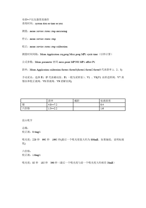
镍
4.8—7.2
0.4
六价铬
1.3—2.2
1.6
昆山乾亨
总镍:
校正液:0.4mg/l
吸光度:220秒995秒1995秒(最后一个吸光度值大约为800mE,如果偏低,说明标液低)
六价铬:
校正液:1.6mg/l
吸光度:85秒185秒390秒(最后一个吸光度与前一个吸光度大约相差50mE)
布朗+卢比仪器简易操作
系统时间:system-data or time or yers
测量:menu-service-status-stop-measuring
停止:menu-service-starus-stop
校正:menu-service-status-stop-calibration
测量时间间隔:Menu-Application-seq.prag-Meas prog-MP1-cycle time(以秒计算)
公式参数:Menu-parameter-密码-meas.point-MP NO-MP1-offset-P1
斜率:Menu-Application-calibration-factors-factor3(factor1 factor2 factor3代表斜率1、2、3)
手动采水:选择P1(P代表蠕动泵、P1一般为采样泵)、V1、V8(V1水样进样阀。V7蒸馏水和校正液阀。V8排液阀。V9消解室阀)
昆西 电脑版操作手册

Power$ync®版本2.07压缩机控制电脑说明手册Quincy控制部分QSI®压缩机系列产品本手册含重要有关安全使用信息,适用于操作或维修此产品的所有人员。
在尝试操作和维修此设备时请先阅读此手册。
手册编号:G906601012004年10月出版Quincy Compressor - Power$ync ® Version 2.07表格内容目录 第一部分-概论 安全警示标志………………………………………………………………………. …. ….…… 1 备用零件订购信息…………………………………………………………………….. …….… 2 序列号/型号标志板……………………………………………………………………. ….…… 2 第二部分-说明 介绍………………………………………………………………………………………... …… 4 容量控制系统……………………………………………………………………………... …… 4 操作模式………………………………………………………………………………….. …… 6 单机模式………………………………………………………………………………. ….. …… 6 多机模式……………………………………………………………………………….. ….…… 7 手动模式…………………………………………………………………………………….….. 7 压力设定………………………………………………………………………………. …….…. 8 含油量 ………………………………………………………………………………….……….. 9 第三部分 安装 单机装置…………………………………………………………………………….……. ……. 11网络装置…………………………………………………………………………….……. ……. 11连接电缆到电路板………………………………………………………………….………….. 11跳线装置……………………………………………………………………………….……….. 12接线盒连接…………………………………………………………………………….…. ……. 12 第四部分 Power$ync 诊断 启动诊断……………………………………………………………………………….…. ……. 13上电诊断 ……………………………………………………………………….………….. 14 第五部分 设置和配置 启动显示 …………………………………………………………………………….……….. 18操作显示 ………………………………………………………………………….………….. 18连续运行模式…………………………………………………………………….………. ……. 19自动/重启设置 …………………………………………………………………….…. ………. 19网络模式 ………………………………………………………………………….……….. 19设置和配置菜单…………………………………………………………………….…….. …… 19自动/重启设置 …………………………………………………………………….………….. 20连续运行设置………………………………………………………………………….…. ……. 21网络配置………………………………………………………………………………. …….…. 21目标压力模式 …………………………………………………………………………….…… 22压力带模式 ………………………………………………………………………………. …. 22顺序和时序…………………………………………………………………………. … ………..24无提升阀网络设置.................................................................................. .... . (29)第六部分-压缩机压缩和诊断维护和诊断菜单 (32)网络诊断 ....................................................................................... . (39)第七部分-报警和停机报警和停机显示 (47)事件记录 (52)第八部分-故障分析 55 启动失败 (56)非程序性关机 (57)低吸收压力 (57)低接收压力 (57)高接收压力 (57)高排气温度 (57)过多油量消耗 (58)放空阀排油 (58)无空气需求时压缩机不卸载................................................................... . (58)当管线压力下降到调节范围的最小值时,压缩机不加载 (59)加载和卸载循环过快 (59)放空阀泄漏 (59)网络通信不稳定或不通 (60)错误显示 (61)微处理器无信息显示 (61)附录A-资料精选和信息140265-1C-板状态指示...................................................................... . (62)140265-4C 继电器板- 遥控接线 (63)140265-5A 继电器板-(可选件) (64)记录 (65)Quincy Compressor - Power$ync® Version 2.07第一部分-概论安全警示标志备用零件订购信息序列号/型号标志板型号标志安全警示标志重要!本手册区别各重要危险标志,以下标志表明了危险的程度。
兰斯顿电子控制器安装包说明书
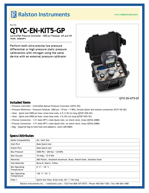
Part No.QTVC-EN-KIT5-GPControlPak Pressure Controller, 1000 psi FieldLab, 6ft and 3fthoses, adaptersPerform both ultra-precise low pressuredifferential or high pressure static pressurecalibrations with nitrogen using the samedevice with an external pressure calibratorQTVC-EN-KIT5-GP Included Items• Pressure Controller - ControlPak Manual Pressure Controller (QTVC-EN)• Pressure Reference - Pressure FieldLab, 1000 psi / 70 bar / 7 MPa, Female Quick-test bottom connection (FLP1-GP-QF)• Hose - Quick-test 6900 psi hose, brass hose ends, 6 ft (1.83 m) long (QTQT-HOS-6ft)• Hose - Quick-test 6900 psi hose, brass hose ends, 3 ft (92 cm) long (QTQT-HOS-3ft)• Process Connection - 1/4" male NPT x male Quick-test, no check-valve, brass (QTHA-2MB0)• Process Connection - 1/4" male NPT x male Quick-test, no check-valve, brass (QTHA-2MB0)• Bag - Zippered bag to hold hose and adapters, nylon (SM-0084)Specs/AttributesMedia Compatibility Air, Inert GasInlet Port Male Quick-testOutlet Port Male Quick-testMax Pressure3000 PSI / 200 bar / 20 MPaMax Vacuum10 InHg / 33.9 kPaMaterials ABS Plastic, Anodized Aluminum, Brass, Plated Steel, Stainless SteelSeal Materials Buna-N, Delrin, Teflon0 °F / -18 °CMin OperatingTemperature130 °F / 54 °CMax OperatingTemperatureHose 1Quick-test Hose, Brass ends, 6ft / 1.9m longSpecs/AttributesHose 2Quick-test Hose, Brass ends, 3ft / 0.9m longPressure Reference NoneProcess Connection NoneReference Connection NoneCountry of origin USAWeight8.90 lbs / 4.04 kgDimensions H: 11.8 in (29.97 cm) x W: 9.8 in (24.89 cm) x D: 7.7 in (19.56 cm)Pressure Controller QTVC-ENCountry of origin USA0.00 PSI / 0.00 mbar / 0.00 kPaFine AdjustmentResolutionHarmonized Code9032.81.0060Inlet Port Male Quick-testMaterials ABS Plastic, Anodized Aluminum, Powder Coated Steel, Stainless Steel, Zippered Nylon130 °F / 54 °CMax OperatingTemperatureMax Pressure3000 PSI / 200 bar / 20 MPaMax Vacuum10 InHg / 33.9 kPaMedia Compatibility Air, Inert Gas, Natural Gas0 °F / -18 °CMin OperatingTemperatureOutlet Port Male Quick-test with cap and chainPressure Media Nitrogen, inert gasSeal Materials Buna-N, Delrin, TeflonWeight8.71 lbs / 3.95 kgDimensions H: 11.8 in (29.97 cm) x W: 9.8 in (24.89 cm) x D: 7.7 in (19.56 cm)Pressure Reference FLP1-GP-QF+/- 0.02% of Full Scale (0-20% of Full Scale), +/- 0.1% of Reading (20-100% of Full Scale)Accuracy - PressureMeasurementBattery Count1Battery Life1000 HoursBattery Type Lithium Ion rechargeable, 4.8 Ah CapacityBurst Pressure4000 PSI / 275 bar / 28 MPaCalibration Certificate NIST traceable (included)Certifications Certified to CSA Standard C22.2 No. 61010-1, Conforms to UL / IEC / EN / AS Standard No. 61010-1, North America - Class 1 Division 1 Groups A-D, T4, (-10 < Ta < 50°C), ATEX - Ex II 1 G Ex ia IIC T4 Ga (-10 < Ta <50 °C), IECEx - Ex ia IIC T4 Ga (-10 < Ta < 50 °C), UN/DOT 38.3 (Lithium Batteries), Complies withPressure Equipment Directive 2014/68/EU, Complies with Low Voltage Directive 2014/35/EU, Complieswith Electromagnetic Compatibility Directive 2014/30/EUCountry Adapters North America, Europe, United Kingdom, Australia, ChinaCountry of origin USAPressure Reference FLP1-GP-QFDatalogging 2 million points (onboard)Engineering Units atm, bar, cmH2O @4°C, inH2O @39°C, kPa, MPa, mbar, psi, inHg @39°F, kgf / cm^2, mmHg @0°C, Torr, mmH2O @4°C, ftH2O @39°F, cmHg @ 0°C, oz / in^2Harmonized Code9026.20.0000LCD Display 3.5 in / 90mm Color TFT LCD DisplayMaterials316 Stainless Steel, Reinforced Polyamide120 °F / 50 °CMax OperatingTemperatureMax Pressure1000 PSI / 70 bar / 7.00 MPaMax Storage165 °F / 75 °CTemperatureMeasurement Type Gauge PressureMedia Compatibility Air, Inert Gas, Natural Gas, Petroleum Based Oil, Water14 °F / -10 °CMin OperatingTemperature-20 °F / -29 °CMin StorageTemperatureMounting Holes 3 x M5 Inserts (10 mm deep)Operating Altitude (max)10,000 ft (3050 m)Power Input90-264 VAC, 50-60 HzPrimary Power Battery PowerProcess Connection Female Quick-testProtection Class Pollution Degree 2 (UL / IEC 61010-1)Relative Humidity0% to 90% (-10 to 35°C) , 0% to 70% (35 to 50°C)Seal Materials Teflon, VitonSensor Type High Precision MEMS14 to 122°F (-10 to 50°C)TemperatureCompensationUSB Connection USB (Type B)Wetted Materials316 Stainless SteelConnector End 1Female Quick-testWeight 2.56 lbs / 1.16 kgDimensions H: 9 in (22.86 cm) x W: 5 in (12.7 cm) x D: 2.5 in (6.35 cm)Hose QTQT-HOS-3ftBurst Pressure27000 PSI / 1860 bar / 185 MPaColor SilverCountry of origin USAFluid Media Air,Inert Gas,Natural Gas,Petroleum Based Oil,WaterHose Length3ft / 0.91 mInner Diameter0.08 In / 3.00 mmLength 3 ft / 92 cmHose QTQT-HOS-3ftMaterials Brass140 °F / 60 °CMax OperatingTemperatureMax Pressure6900 PSI / 475 bar / 48 MPaMax Vacuum-30.00 InHg / -101.6 kPaMedia Compatibility Air, Inert Gas, Natural Gas, Petroleum Based Oil, Water Min Operating-40 °F / -40 °CTemperatureMinimum Bend Radius 1.00 In / 26 mmOuter Diameter0.20 In / 6.00 mmType QTProcess Connection QTHA-2MB0Burst Pressure20000 PSI / 1380 bar / 140 MPaCountry of origin USAMaterials BrassMax Operating225 °F / 105 °CTemperatureMax Pressure5000 PSI / 350 bar / 35 MPaMax Vacuum0.00 InHg / 0.0 kPaMin Operating0 °F / -18 °CTemperatureSeal Materials Buna-NWrench Size9/16 In15 mmConnector End 11/4" Male NPT (ASME B1.20.1)Connector End 2Male Quick-testDimensions H: 1.29 in (3.28 cm) x W: 0.56 in (1.42 cm)Bag SM-0084Materials Zippered NylonCountry of origin USAWeight 3 oz / 85 gramsDimensions H: 6 in (15.24 cm) x W: 1 in (2.54 cm) x D: 7 in (17.78 cm)。
诺汤克 迪伦 耳机说明书

PhilipsWireless Bluetooth®headphonesOn-ear WhiteSHB9150WT Premium sound quality, wired or wireless one touch pairingDigital enhancement and superior drivers deliver booming bass with clear sound. Deluxe FloatingCushions allow for full multi-directional earshell adjustment, ideal for comfortable listening when wired or wirelessPremium sound quality•Digital enhancement reveals hidden notes and nuances•Superior speakers deliver high performance soundBrings convenience to your lifestyle•Supports Bluetooth2.1+ EDR HSP/HFP/A2DP/AVRCP mobile devices•Pair with your NFC enabled device with one touch•Choice of wireless or wired listeningDesigned for long wearing comfort•Natural comfort fit from deluxe memory-foam FloatingCushions•Light and slim headband designBe free from hassle•Easy to use smart controls for music listening & callsHighlightsDeluxe FloatingCushions The innovative deluxe FloatingCushions design allows for full multi-directional, automatic cushion adjustment, without a traditional C-hinge construction. This optimises stability by applying pressure evenly onto your head and ears and creates a comfortable fit.Digital enhancementBooming, superior bass with high performance drivers and digital enhancement.Easy NFC pairingPair with any NFC enabled device effortlessly. Gone is complicated wireless headphone pairing. Our new NFC technology is user friendly and easy to use, with one touch pairing for any NFC enabled smart device.Light and slim headband design The light and slim headband design makes these headphones perfect for outdoor use and unnoticeable even after hours of wear.Smart controls Switch easily between music and calls with smart controls (volume, track and toggle control).Superior speakers 40mm precision drivers with neodymium magnets produce rich bass and high performance sound.Wired or wireless Use as a wireless headphone or connectdirectly with a 3.5mm plug.Issue date 2020-07-08 Version: 2.2.312 NC: 8670 001 09004 EAN: 69 23410 72487 5© 2020 Koninklijke Philips N.V.All Rights reserved.Specifications are subject to change without notice. Trademarks are the property of Koninklijke Philips N.V. or their respective owners.SpecificationsSound•Frequency range: 18 - 21 000Hz •Impedance:32Ohm•Magnet type: Neodymium•Maximum power input: 50 mW •Sensitivity: 103 dB•Speaker diameter: 40 mmDesign•Color:WhiteConnectivity•Audio Connections: 3.5mm Line in •Bluetooth profiles: A2DP, AVRCP, HFP, HSP •Bluetooth version: 2.1+EDR•Maximum range: Up to 15 mAccessories•Audio cable: 1.2 m audio cable for flight mode operation•Quick start guide: Included•USB cable: Included for charging Convenience•Call Management: Answer/End Call, Reject Call, Last number redial, Microphone mute, Call on Hold, Switch between call and music •Volume controlPackaging dimensions•EAN: 69 23410 72487 5•Packaging dimensions (W x H x D):19.5 x 20 x 8 cm•Packaging dimensions (W x H x D):7.7 x 7.9 x 3.1 inch•Gross weight: 0.328 kg •Gross weight: 0.723 lb•Nett weight: 0.185 kg•Nett weight: 0.408 lb•Number of products included: 1•Packaging type: Display•Tare weight: 0.143 kg•Tare weight: 0.315 lb•Type of shelf placement: BothPower•Battery Type:LI-Polymer•Battery weight: 10.6 g•Rechargeable•Music play time: 9 hr•Standby time: 200 hr•Talk time:9hrOuter Carton•Gross weight: 2.886 lb•Gross weight: 1.309 kg•GTIN: 1 69 23410 72487 2•Outer carton(L x W x H): 25.5 x 20.8 x 22.4 cm •Outer carton(L x W x H): 10 x 8.2 x 8.8 inch •Nett weight: 1.224 lb•Nett weight: 0.555 kg•Number of consumer packagings: 3•Tare weight: 1.662 lb•Tare weight: 0.754 kgProduct dimensions•Product dimensions (W x H x D):5.9 x 7.0 x 2.8 inch•Product dimensions (W x H x D):14.9 x 17.8 x 7 cm•Weight: 0.14 kg•Weight: 0.309 lb。
Cequent 工具杆说明书

Rev. 102313 74407_INUtility JackModel Number:74407 74407HD 74410 74410HD 74413 74413HD74412 74415 70429For assistance with this product or to order replacement parts, please contact:Cequent Consumer Products, Inc. 29000-2 Aurora Road Solon, OH 44139Technical Service: (800) 234-6992 Date of Purchase: _____________________This Instruction Sheet contains IMPORTANT safety information. Please read and keep for future reference.• Rolled Acme Thread and Anti -Friction thrustBearings • High Strength TubingREAD and FOLLOW all instructions and safety messages before using theTHIS WARNING IS GIVEN IN COMPLIANCE WITH CALIFORNIA PROPOSITION 65WARNING:This product contains chemicals known to the state of California to cause cancer, birth defects or other reproductive harm.Installation InstructionsBefore mounting the jack confirm that there will be no interference from the tow vehicle, tongue, ground, and any other mounted accessories while stationary or in motion. Before installing, check for interference in all positions including handle swing and swivel positions if applicable. Check for interference again after installation is complete.Installation Instructions Cont.’dMaintenance InstructionsThe following procedures should be performed at least annually:For side-wind models, the internal gearing and bushings of the jack must be kept lubricated. Apply a small amount of automotive grease to the internal gearing by removing the jack cover, or if equipped, use a needle nose applicator or standard grease gun on the lubrication point found on the side of the jack near the crank. Rotate the jack handle to distribute the grease evenly. A lightweight oil must be applied to the handle unit at both sides of the tube for side- wind models. If equipped, the axle bolt and nut assembly of the caster wheel must also be lubricated with the same light weight oil. For top-wind models, apply a lightweight oil to the screw stem. If this product is used in a marine environment, flush the jack assembly and bushings with fresh water, and apply fresh lubricant.REESE One (1) Year Limited Warranty1. Warranty. Cequent Consumer Products, Inc. warrants to the original consumer purchaser ("You") thatthe Product will be free from defects in material or workmanship for one year from the date of your retail purchase. Cequent Consumer Products, Inc. makes no other warranties. If the Product does not comply with the Warranty, Cequent Consumer Products, Inc. will replace the Product without charge and within a reasonable time or, at Cequent Consumer Products, Inc. option, otherwise refund the purchase price. 2. Limitations on the Warranty. The Warranty does not cover the following: (a) normal wear and tear;(b) service or labor charges incurred in removing or replacing any Product; (c) the finish on the Product; (d) a Product that has been damaged through abuse, neglect, misuse or as a result of any accident or in any other manner ; (e) a Product which is misapplied, overloaded , or improperly installed; and (f) a Product altered in any manner by anyone other than Cequent Consumer Products, Inc. 3. Obligations of Purchaser. To obtain the benefits of the Warranty, You must promptly present thedefective Product and proof of purchase to Cequent Consumer Products Inc., 29000-2 Aurora Road, Solon, Ohio 44139 or any of its branches, factories, or authorized dealers listed in local directories. Any returned Product that is replaced or refunded becomes the property of Cequent Consumer Products, Inc. 4. Legal Rights. This Warranty gives You specific legal rights, and You also may have other rights whichvary from state to state. ANY IMPLIED WARRANTY OF MERCHANTABILITY OR FITNESS FOR A PARTICULAR PURPOSE ON ANY PRODUCT SHALL BE LIMITED TO ONE YEAR FROM THE DATE OF RETAIL PURCHASE BY YOU. Some states do not allow limitations on how long an implied warranty lasts, so the above limitation may not apply to You. 5. Remedy Limits. Replacement of the Product or refund in the manner provided above is Your exclusiveremedy and shall constitute fulfillment of all liabilities of Cequent Consumer Products, Inc. to You whether based on contract or otherwise. Cequent Consumer Products, Inc. shall not be liable or assume responsibility for the loss of the use of any vehicle, loss of time, rental of vehicles, loss or damage to personal property, expenses such as gasoline, telephone, lodging, or towing, or any other incidental or consequential damages incurred as a result of the use or ownership of any Product. Some states do not allow the exclusion or limitation of incidental or consequential damages, so the above limitation or exclusion may not apply to You. Any of the above remedy limitations shall be inoperative to the extent they are not permitted by applicable state law.Cequent Consumer Products, Inc. 29000-2 Aurora Road Solon, OH 44139Technical Service: (800) 234-6992 。
eVscope eQquinox V1.1用户指南说明书

eVscope eQuinoxUser GuidePrepare to Be AmazedCONTENTS:Instructions ……………………………………………………………………………………… 1. Tripod installation ………………………………………………………………………….. 2. Adjusting level bubble ……………………………………………………………...……… 3. eVscope eQuinox installation ………………………………………………………..…… 4. Starting the eVscope eQuinox …………………………………………………………… 5. Removing the dust cap …………………………………………………………………… 6. Connecting the eVscope eQuinox to your smartphone ………………………………... 7. Focus ………………………………………………………………………………………... 8. Observation ………………………………………………………………………………… 9. Park mode ………………………………………………………………………………….. 10. Improve your observations ………………………………………………………………... 11. Mirror alignment ……………………………………………………………………………. 12. Charge/discharge ………………………………………………………………………….. 13. Data …………………………………………………………………………………………. Safety instructions ……………………………………………………………………………… Maintenance …………………………………………………………………………………….. Specifications …………………………………………………………………………………… Declarations …………………………………………………………………………………….. p. 4 p. 4 p. 5 p. 5 p. 5 p. 6 p. 6 p. 6 p. 8 p. 8 p. 9 p. 9 p. 11 p. 12p. 12 p. 13 p. 13 p. 14InstructionsBox content:- eVscope eQuinox + Bahtinov mask included in the tube top cover- Tripod- Power supply with exchangeable plugs (EU, USA, UK)- Quick start guide- User Guide- Accessories box with toolsRequirements:- Avoid directly exposing the eVscope eQuinox to strong wind and try to shelter it from moderate winds to improve your observations.- Use the eVscope eQuinox on stable ground that does not vibrate when you walk near it.- Use the eVscope eQuinox under a clear sky.- Locate the eVscope eQuinox away from direct streetlight.- For best results, avoid a full moonUsing the telescope, please follow these steps carefully:1. Setup the tripod:Open the legs of the tripod and adjust the device to the height that works best for you.Warning: The interna l tripod’s screws could have loosened during shipment.Please check that all screws are tightened. If not, you can tighten them with the specific tools you can find in the accessories box.2. Adjust the legs to put the bubble level in the middle of the black circle, as in the image.Note: each time you move your eVscope, we recommend resetting the level bubble.3. Loosen the 2 tripod screws. Install your eVscope vertically on the tripod and tighten the screws. Becareful not to tighten it too hard.4. Start the eVscope by pressing the ON button for 2 seconds. When you see a red light, the eVscopeis on and ready to use.Warning: if you turn on your eVscope in daylight, you might not see the button light because of its low intensity. It has been set up like this, so it won’t dazzle you at night.Battery is not fully charged when shipped.5. Remove the dust cap from the top of the tube.6. Connection to the smartphone:o Download the Unistellar app from the Google Play Store or Apple Store.o Turn on your smartphone’s Wi-Fi. o Check available Wi-Fi networks.o Connect your smartphone to the eVscope eQuinox’s Wi-Fi network named eVscope-xxxxxx (the network’s name consists of eVscope and six random characters). o Launch the Unistellarapponyoursmartphoneo Warning: the connection between your eVscope and your smartphone may sometimes be lost, in this case please restart your application. If you encounter broken connections, we advise you to disable Auto-Lock.7. Focus:o Using the in-app joystick, lower the telescope to around 45°.o Basic focus: Adjust the focusing wheel at the bottom of your eVscope to align the visual cue with the top screw.Note: To get a perfect focus, the visual cue might not be exactly aligned with the top screw to have the perfect focus. You can focus "by eye" or focus precisely using the Bahtinov mask (recommended for excellent results).o Accurate focus: To ensure perfect accuracy, point the eVscope on a bright star and use the Bahtinov mask to adjust the focus and the coma (see Mirror Alignment).i. Here is how to focus with the mask. In the « Explore » tab of your app, go to « Star », and select thefirst one. Select « GoTo » to move the eVscope on it. Go to « eVscope » tab, then touch the Settings icon on the top right of your screen and activate the « Auto » mode. Put the mask on top of the tube. This will create a specific diffraction pattern for that bright star, with a central line and two spikes forming an X. If the central line is positioned exactly in the middle of X, it means your eVscope is perfectly focused. To achieve this result, you just need to manually rotate the focusing wheel at the bottom of your eVscope and observe the results.The orientation of the cross does not matterii. In these three images, you can see the star Rigel observed with our mask. The first two images are out of focus, but by rotating the wheel, we were able to achieve perfect focus.iii. The Bahtinov mask is included in the cover. To use it you should remove the mask from the cover and install it on the eVscope, as in the pictures.iv. In case you need to adjust the coma, use the two screws of the adjustment mechanism (see Mirror Alignment on next page).8. Observation:o Check the Quick Start Guide for detailed explanations on how to use your eVscope.9. Park:o When you are done observing, use the « Park my eVscope » function so it automatically moves to the zenith position and turns itself off. First, the tube will go a little further than thezenith, then it will slowly go back. You will find the option « Park my eVscope » in the « User» tabo Put the dust caps back on the tube.10. To improve your next observations:o Adjust the gain and the exposure time in Live View mode.o Adjust the contrast and brightness in Enhanced Vision mode.o Set up your observing conditions in the « Explore » settings (city, suburb, countryside).o Check and adjust the mirror alignment (below). o Check the battery charge level in the « User » tabo Share your observations with the community by sending us your data (Download data , then Upload my data ). o Enjoy the multi-user experience.o Contribute to science by joining eVscope observing campaigns. o Check the online FAQ to learn more about your eVscope’s capabilities.11. Mirror Alignment:o Mirror alignment is advised after each time your eVscope is having a long journey.o For this procedure, you will need:a. The smallest hex key provided in the toolbox (S2 3mm),b. A clear sky with visible bright stars.o Set up the eVscope using the 1. INSTALL and 2. CONNECT and 3. FOCUS & TRACK sections of the Quick Start Guide.o Point toward a bright star by selecting a visible one in the list of proposed stars. o Center the target using the joystick.Note: the joystick of the app can be used in 2 different ways: drag the yellow dot for fast movement or simply touch the edge of the disc for slow movement. The short touches allow a slow movement. In the « eVscope » tab, display the settings by touching the icon at the top right and activate the « Auto » mode.o Fully rotate the large focus wheel clockwise without forcing. You should see this:Bad alignment(the cross is not centered)Good alignment (the cross is centered)o If the dark cross is not centered (as shown in the above image on the left), you need to realign your mirror. o Find the smallest hex key (S2 3mm) in the toolbox.o First, move the telescope with the in-app joystick (touch the edge of the circle quickly) to put the star at the edge in the direction indicated in the table below:o Then turn the vertical or horizontal screw in the mirror mount to put the star backat the center. For example, if the cross is too high:1. Put the star on the edge ofthe screen with the in-appjoystick.2. Use the hex key to turn the screw (in this example the vertical screw)3. Put back the star at the center of the screen. The cross will recenter itself o Repeat the procedure until the cross looks centered. You might have to do itseveral times.o Move back the focus to the default position by aligning the visual cue with the topscrew (Section 3 in the Quick Start Guide).o Move toward a target and enjoy. The image should look better now.11. Charge/Dischargeo The eVscope eQuinox can be used while charging.o It can take from 7 to 8 hours to fully charge it.o When the eVscope is charging, you will see a blue flashing LED that will go fromsix flashes to none. Flashes decrease as the battery gets more charged.o We strongly advise not to recharge your eVscope below 10°C.o When the battery is low, the performance of the eVscope can be compromised.You can see the battery charge level in the "User" tab of the app. A fully chargedbattery is all yellow, a fully discharged battery is black with a yellow border.o We advise to only use the USB-C charger provided by Unistellar.o You can also use an external battery to recharge your eVscope.o You can charge your smartphone with the eVscope. Plug it to the USB-A port, nextto the USB-C port.12. DataRaw data is saved during Enhanced Vision. You can empty your SD card when the storage is full.To empty the SD card storage, first select Download data. Then, when it is done, select Upload my data.Download data sends data from eVscope to your smartphone. Upload my data send data from your smartphone to the Unistellar servers.You are your observations owner. By sharingyour data with us, you allow Unistellar to provide its users with continuous improvement of their observation experience.It also makes scientific discoveries possible,for which your contribution will be mentioned if you wish. As usual in these cases, the results ofanalyzes will be the property of those who analyzed it: Unistellar and its scientific partners.Safety instructionsYour eVscope eQuinox and its accessories are not toys. Do not allowsmall children to play with them because children could hurt themselvesor others or damage your device. Keep your device and all its parts andaccessories out of the reach of small children.Your eVscope eQuinox is not meant to be used in wet environment. Asevery electronics object (as exception of the waterproof ones), if wateror another liquid enters the eVscope it can be permanently damaged.You should immediately turn off the power and dry it.Do not look at the Sun without an adapted filter. You eVscope eQuinoxcan be definitively damaged also after a short exposure. There is also animportant fire hazard.Furthermore, do not expose your eVscope at temperatures above 50°Cor below -20°C, the performances can be compromised by extremetemperatures.Your eVscope is fragile, do not let it drop or fall. In case of shocks, it canbe permanently damaged.Maintenance1. Storage:o Store the eVscope eQuinox in its original packaging or in its backpack.o Store the eVscope eQuinox with its cover, to avoid dust to enter in the device.o Do not store the eVscope eQuinox with empty battery.o Do not store the eVscope eQuinox in wet environment and temperatures below -20°C or above 50°C.o Do not store under direct sunlight.2. Mirror removal and cleaning:o The mirror can be removed by removing the 4 screws on the back of the adjustment mechanism, as in the picture:o Gloves must be used to manipulate the mirror.o Once the back removed the mirror can be cleaned with dry compressed air.o No liquids should be used to clean the mirror.o No wet tissues should be used to clean the mirror.3. Tripod maintenance:o The tripod screws could untighten with the use.o Three different “tripod tools” are provided to tighten the screws of the tripod in case they are slightly loosened.4. Battery removal:o The battery is not meant to be removed by the user.SpecificationsModel: eVscope eQuinoxMirror specifications: diameter 112mm, focal length 450mm, material BK7Battery specifications: 9 hours life, capacity 15 000mAhPower supply unit (PSU) input: 100-240V ~50/60 Hz 0.6A Max; Output: 5.0Vdc, 3AWIFI frequency and bandwidth: 2.4 GHz, 72.2 Mbit/sWIFI range: 50m in free spaceInput/output: USB-C (PSU); USB-A (smartphone recharge)Tripod: aluminum, adjustable height; designed for the eVscope DeclarationsHereby, Unistellar SAS declares that the radio equipment type eVscope eQuinox is in compliance with Directive 2014/53/EU, the FCC 47 CFR Part 15 and the ICES-003 / NMB-003 standards. The full text of the declarations of conformity is available at the following internet address: .Contains: FCC ID: 2ABCB - RPI3AP. Contains IC: 20953 - RPI3AFor Canadian users: A separation distance of 20cm or more is required between the user and the device according to Canadian standard RSS-102 — Radio Frequency (RF) Exposure Compliance of Radiocommunication Apparatus (All Frequency Bands) (https://www.ic.gc.ca/eic/site/smt-gst.nsf/ eng/sf01904.html)RecyclingThis device is compliant to the 2012/19/UE directive and should not be disposed in household Array waste. The special waste disposal varies according to local rules. The correct recycling ofelectronic devices helps to preserve environment and health.Unistellar SAS19 rue Vacon13001, Marseille FranceN° SIRET 81233935600022Designed in France – Made in China。
超短基线操作说明书
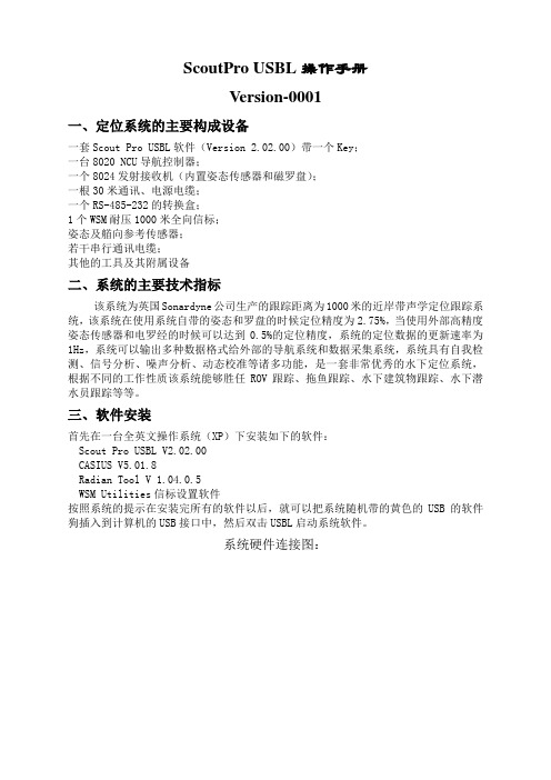
ScoutPro USBL操作手册Version-0001一、定位系统的主要构成设备一套Scout Pro USBL软件(Version 2.02.00)带一个Key;一台8020 NCU导航控制器;一个8024发射接收机(内置姿态传感器和磁罗盘);一根30米通讯、电源电缆;一个RS-485-232的转换盒;1个WSM耐压1000米全向信标;姿态及艏向参考传感器;若干串行通讯电缆;其他的工具及其附属设备二、系统的主要技术指标该系统为英国Sonardyne公司生产的跟踪距离为1000米的近岸带声学定位跟踪系统,该系统在使用系统自带的姿态和罗盘的时候定位精度为2.75%,当使用外部高精度姿态传感器和电罗经的时候可以达到0.5%的定位精度,系统的定位数据的更新速率为1Hz,系统可以输出多种数据格式给外部的导航系统和数据采集系统,系统具有自我检测、信号分析、噪声分析、动态校准等诸多功能,是一套非常优秀的水下定位系统,根据不同的工作性质该系统能够胜任ROV跟踪、拖鱼跟踪、水下建筑物跟踪、水下潜水员跟踪等等。
三、软件安装首先在一台全英文操作系统(XP)下安装如下的软件:Scout Pro USBL V2.02.00CASIUS V5.01.8Radian Tool V 1.04.0.5WSM Utilities信标设置软件按照系统的提示在安装完所有的软件以后,就可以把系统随机带的黄色的USB的软件狗插入到计算机的USB接口中,然后双击USBL启动系统软件。
系统硬件连接图:四、软件运行及系统设置双击桌面上的USBL图标启动软件:软件启动后,点击edit菜单中的IO Ports…,进入系统的接口设置:在这个页面上将完成系统所有设备的接口设置工作,主操作图如下:首先将8020NCU导航控制器添加到系统中,连接成功以后系统会自动找到该甲板单元并且显示出甲板单元的硬件版本号,其主要的参数设置如下:(备注,上面的设定假象为NCU连接到PC的COM1口上)然后添加8024发射接收机,系统的通讯接口协议如下所示,在设置完成以后系统会自动复位发射接收机,这个时候需要耐心的等待几十秒钟:在等待了几十秒钟以后,系统会找到Transceiver并且显示出它的版本号:添加系统自带的姿态传感器和艏向系统,设置如下(当然我们可以根据系统连接的实际情况来设定系统所使用的端口,此处显示的是系统连接到NCU Port 6A上的情况):添加外置的姿态传感器,当前的端口选取的是NCU Port 7A:后设置好输入的数据格式和通讯协议既可;以上所有的接口设置完成以后一套系统的系统设置就算结束了,当然用户可能希望同部输出定位数据到外部的导航平台,那么用户只需要按照相同的设定添加一个OUT t(9种可用字符串输出),然后定义好端口和通讯协议就可以了;添加将要跟踪的信标点击Edit的下拉菜单然后选取Transponders,就会出现下面的页面;点击Add…然后在按照下图进行信标的选取,缺省默认的是WSW A1信标下图:然后继续添加信标,可以添加的WSW信标还有八个信标(共有九个信标,用户购买了A3、B3、C2四个信标),当然需要根据用户的需求来进行设置,若跟踪多个新标就逐一设定,若仅仅跟踪一个新标只需要把这个新标添加上就可以了:三个信标添加完成以后就如下图所示(这里还添加了一个高频的TZ\OBC信标):在接口和信标添加完成以后系统就可以进行水下信标(目标物)跟踪的工作了,我们在跟踪目标物的时候需要做的仅仅就是点击该信标就可以了,如下图:开始跟踪以后,系统就会在设定的参数下进行工作了,系统的更新数据的刷新率也将同用户的设定相一致(最快1HZ ),另外如果用户设定了同步输出的数据格式的话,那么系统会通过设定的端口按照设定的数据格式进行数据的输出。
QuiQ充电器使用说明(中文)

请保留这份重要的安全使用说明使用前请仔细阅读这份使用说明,其中包含了重要的安全操作和安全介绍电池安全信息警告:使用充电器仅用算法选择适合于特定电池类型。
其他的使用可能会导致人身伤害或损害。
铅酸电池在正常操作过程中会生成易爆氢气。
所以在充电时请远离火花,火源以及易爆物品。
充电时,电池要发放在通风顺畅的地方,不要给冻结的电池充电,请提供足够的通风环境进行充电。
请认真学习电池厂家提供的电池说明书,例如,建议的充电率;充电时是否要去掉电池壳盖等。
电气安全信息危险提示:有电击的危险,充电器的连接线连接到充电接口时,请务必确保充电座的安装完好无损,而且符合用户使用地代码和条令。
接地插座可以降低电击地危险,不要用对地适配器或是改动插头。
请不要触摸输出接头非绝缘的部分,或是非绝缘地电池端子。
在给电池充电,接通或是断开连接之前,请断开连接之前,请断开AC 连接。
请不要打开或拆卸充电器,如果充电器的AC 供电线束被破坏,或是充电器受到严重的撞击,或是有其他破坏的情况下,请不要使用充电器。
请不要用小孩使用充电器。
注意:在充电过程中充电器散热板会发热。
如果需要在充电时处理充电器,小心烫伤。
1充电器要可靠接地,在使用延长线(拖线板)的时候,请使用3芯12号,不要超过30米的线束。
2一条15A 的电路,只能连接一个QuiQ 充电器,以免电路过载。
3充电器10个LED 显示灯LED显示“充电,自检测” 电表(琥珀色灯)80%充电(琥珀色灯)100%充电(绿灯)AC 接通(琥珀色灯) 故障(红灯)固定:在正常充电阶段,显示的是大概电流闪烁:充电器内部的温度太高,减小输出电流如果11秒钟没有电池连接,会一直显示算法#1-6固定:完成全部充电过程的大部分,即已充80%处于吸收阶段闪烁:没连电池,根据闪烁的次数指出算法号固定:完全充电,充电器处于维护状态闪烁:充电器吸收阶段完成,结束固定:AC 电源正常闪烁:AC 低电压,检查电压和延长线的长度闪烁:充电器故障,重启充电器,请参照以下故障分析使用说明4充电器单个LED 的显示(内部或外部)1对于铅酸蓄电池来说,在每次充电完成后,一定要检测调节电解液液面高度,并且按照电池厂家的要求添加蒸馏水到规定的高度,请按照电池厂家的维修手册和安全指导手册来进行。
雷尼绍探头设定及使用
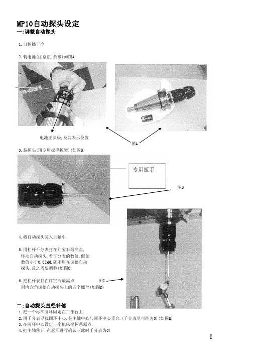
MP10自动探头设定一:调整自动探头1.刀柄擦干净2.装电池(注意正.负级)如图A电池正负极,及其表示位置图A3.装探头(用专用扳手扳紧)(如图B)图B4.将自动探头装入主轴中5.用杠杆千分表打在红宝石最高点,转动自动探头,看百分表的数值,假如数值小于0.02MM,就不用在调整自动探头,反之需要调整(如图C)6.把杠杆表打在红宝石最高点, 图C用内六角调整自动探头上的四个螺丝(如图D)二:自动探头直径补偿1.把一个标准圆环固定在工作台上.2.用千分表寻找圆环中心,是主轴中心与圆环中心重合.(千分表尽可能为0)(如图E)3.在圆环中心设定一个机床坐标系原点.4.把主轴移开,在返回进行确认.(此时千分表为0)Ⅰ调整螺丝位置图D 图E (FM MP3的调整螺丝在圆锥盖得里面)5.把自动探头放入主轴中,走到设定的原点(如图F)6.在MDI方式下,输入CALL OO18,启动.(自动探头加电,会有几秒的延时) (FMMP3输入 : CALL OO16)7.把自动探头下降到基准圆环平面以下10MM左右.8.在MDI方式下,输入CALL OO21,启动.(将设定的原点读入MSB原点)9.画面放在"测量结果显示",按"MSB原点"(MSB原点坐标,No.3号坐标系).10.输入VNCOM[1]=8,启动.11.将画面放在"测量结果显示"按"传感器",用手轻碰探头,看到传感器画面有黄色的指示灯会亮,进行信号确认,表示探头有信号.12.在MDI方式下,输入:CALL OO10 PMOD=9 PDI=50 POVT=3 启动.PMOD=9 表示自动探头半径补偿 PDI=50 表示基准环的准确直径 POVT=3表示超行程距离13.测量结果在"测量表示画面",按"MSB刀具ON/OFF"键.半径补偿的1-4号半径补偿值为探头4个方向的补偿值.14.在MDI方式下,输入:CALL OO19 启动(表示断电)(FMMP3输入:CALL OO17)三:自动探头长度方向补偿1.换基准棒.(记下标准棒的长度,假如为199.9MM)2.将基准棒的端面与量块轻微接触到(如图G).3.在此位置设定Z方向的原点.a.绝对长刀具补偿:运算199.9b.相对刀具补偿:运算04.抬起基准刀具,主轴换上自动探头.5.在MDI方式下输入:CALL OO18 启动 <VNCOM[1]=8检测信号>6.在手动方式下,将自动探头放在量块的上方,大约10MM左右(如图F).* 相对补偿,PLI=自动探头长度-基准棒长度(大概距离)9.CALL OO19 (自动探头断电)四:复制补偿数值图F1.将"MSB刀具ON/OFF"中的,半径补偿1-4号复制到5-20号,长度补偿的5号复制的1-4号.2.在MDI方式下,输入:CALL OO22 Ⅱ间距10MM左右 图G 图H使用自动探头一:内径测量1.探头放在孔的中心位置(大概),把探头的顶端移到孔内.2.MDI方式下:输入 CALL OO18 启动(FMMP3输入CALL OO16)3.测量: CALL OO10 PMOD=7 PDI=50 启动 .(PMOD=7表示测量孔德半径.PDI=50表示孔直径的预想值) 4:测量结果在"测量结果显示"中.5.设定孔中心为原点: CALL OO20 PHN=3 PX=0 PY=0 启动.(PHN=3表示为3号坐标系,PX,PY表示X与Y偏移量) 6:在MDI方式下,输入: CALL OO19 启动(FMMP3输入:CALL OO17)二:外径测量1.探头放在孔的中卫,并且在零件的上方.2.CALL OO18启动.3.测量: CALL OO10 PMOD=6 PDI=100 PIN=25 启动 (PMOD=6表示测量外径 PDI=100表示外径的预想值 PIN=25表示从探头顶端下降25mm.)4.以下操作同测内径操作.三:X向的端面测量 1.探头放在离被测平面不远的地方.2.在MDI方式下,输入: CALL OO10 PMOD=1 PEI=-255 启动 .(PEI=-255表示X向的预想值,预想值=当前位置+到被测面得距离) 3.设原点同上,设好原点后,再次确认,输入:CALL OO10 PMOD=1 PEI=0启动 PEI=0表示确认面与测量面差值为0.四:Y向端面测量1.测量:CALL OO10 PMOD=2 PEI=800 启动2.设原点和再次确认操作步骤同上.五:Z向测量.1.探头方在被测零件平面的上方.2.在MDI方式下,输入: G56H5 启动,HS=5表示MSB刀具长度补偿为五号.3.测量:CALL OO10 PMOD=3 PEI=-111 启动4.设原点和再次确认同上.六:测量两点间的距离探头放在被测量两点的大约中间位置.*X向测量:CALL OO10 PMOD=11 PELI=60 启动 *Y向测量:CALL OO10 PMOD=12 PELI=85 启动七:测量两端面的距离探头放还在被测两端面的中间,并放在零件的上面.* X向测量:CALL OO10 PMOD=11 PELI=130 PIN=30 启动* Y向测量:CALL OO10 PMOD=12 PELI=130 PIN=30 启动END Ⅲ。
- 1、下载文档前请自行甄别文档内容的完整性,平台不提供额外的编辑、内容补充、找答案等附加服务。
- 2、"仅部分预览"的文档,不可在线预览部分如存在完整性等问题,可反馈申请退款(可完整预览的文档不适用该条件!)。
- 3、如文档侵犯您的权益,请联系客服反馈,我们会尽快为您处理(人工客服工作时间:9:00-18:30)。
则会造成重大的设备和人身伤害事故 4. 在机组运转时,绝不要拆卸或松动任何管路元件、接头、堵头和联接件,不要扳动安全
阀。机组内充满具有压力的热工质,能引起严重的人身伤害事故。 5. 在对机组进行任何维修工作之前,必须确认:
返修的压缩机机头:从装运出厂日起 12 个月内。
备品备件:从代理商出售之日起 90 天内,或装运出厂日起一年内。
对于非昆泰克制造的产品,在可行的条件下,将直接引用原制造商的担保条款。在担保 期内,必须在发现瑕疵 30 天以内以书面通知昆泰克或代理商,并附所有供辨认鉴定之 详细资料,包括出厂序号、机型、购买日期等。
昆泰克在此担保条款下的单一责任为,依据判断对任何被证明为瑕疵品的产品或零件加 以修复,更换或按买价退款。在必要的情况下,昆泰克公司可要求用户将瑕疵产品或零 件以预付运费方式送回厂家进行检查工作。
昆泰克对修理之产品,零件或更换之零件(由其自己制造者)在正常使用、维护、维修 和保养情况下,担保期为 90 天或该修理产品的剩余担保期。
安全警示标志
本手册中,对涉及安全的操作和事项进行了危险界定,并根据操作可能对机器造成破坏的严 重性和对人身伤害的程度加以分级,分别以下述标志并用黑体字进行表述和说明。
“注意”表示可能会造成机器一般性破坏或人员伤害的不安全因素。 “警告”表示可能会造成财产损失或人身伤亡的不安全因素。 “危险”表示会造成重大事故或人身伤亡的不安全因素。 “危险”表示超过安全等级的电压会造成严重的人身伤亡的不安全因素。所有的电气
对下列责任,本担保条款不适用,而且昆泰克亦无责任或义务
A. 间接造成的,附带的或特殊的损失或损坏。 B. 正常磨损,非正常使用条件,疏忽或不当使用设备,不当储存或运输造成的损坏。 C. 不遵守操作指令的规定,规范或其他特殊的销售条件。 D. 劳工费用,不当操作(运转)维护和非卖方或卖方授权之维修人员所做维修所致
绝不可在不安全状况下起动机组;若机组已出现问题,不要试图开机,应切断电源, 作出明显标志,使不知情的人不至于误操作。
压缩空气具有危险性,只有在整个压缩机系统里的压缩空气都已放空的情况下方能对 机组进行维修和保养。
不要改动机组的内部结构及控制方式,除非有昆泰克公司的书面认可。 作好日常保养和维护,每天都应仔细检查机组,查看是否有泄漏及零件的松动、损坏、 调节失灵或零部件丢失等情况,发现问题及时处理。
I计生产的 QGD 系列螺 杆空气压缩机的安全注意事项,各系统和组件的结构功能以及操 作维护方法。
操作人员应仔细阅读完本操作手册,在充分了解机组各系统 和组件的结构功能和安全注意事项之后,方能对机组进行操作和 维护。除本操作手册中有说明的外,如用户不按本操作手册的操 作维护规程进行操作和维护保养,或自行对机器进行解体和改 装,或使用了不是昆泰克公司指定的零件,您将会失去索赔的权 利。
作业必须由具有资格的电工担任。 “注意”表示热的表面可能会造成财产损失或人员伤害的不安全因素。
“注意”表示重要的安装、操作和维修信息。
VI
安全提示
操作和使用压缩机之前务必仔细阅读
警告
压缩空气及压缩空气系统具有危险性! 不遵守本操作手册的操作程序和安全注意事项,会有酿成事故和造成您自己 或其他人员伤亡的可能性! 操作和维护压缩机之前,必须仔细阅读和弄懂本操作手册!
压缩机零件的损坏或爆炸。 5) 不要改变安全泄压阀的压力设定,也不要限制其功能或用堵头来替代它,否则会引
起压缩机零件或系统的超压而造成人员伤亡和财产损失。 6) 不要在压缩空气系统中使用塑料管道,橡皮管或钎焊的连接件。如不能保证压缩机
管道与系统管道的匹配会产生有害的噪音。 7) 不要使用可燃的或有毒的溶剂来清洗空气过滤器或任何部件。 8) 压缩机运行时不要拆掉任何防护罩或隔音面板,禁止机器运行时对机组的任何部分
我们尽量保证手册的完整性和准确性,但昆泰克公司将保留对 产品不断研究和改进的权利而不负有对以前出厂的产品进行修 改和改进的义务,当产品设计变更时将不再另行通知。
生产许可证: 压缩机型号: ____________________ 压缩机系列号:____________________ 电机型号: ____________________ 电机系列号: ____________________
本操作手册未向您提供零部件图解目录。如果您需要向本公 司订购零件,请查阅零件手册。需要提请您注意的是,昆泰克公 司对产品不断进行研究和改进,一定时期以后,零件手册的内容 与产品的实际情况可能会有所出入。在您订购零件之前,请先与 本公司服务(零件)部核实。
本操作手册对电机及电气系统和维护作了一般性的介绍,但 您在使用和维护本机组之前,如还有疑问,请与当地经销商或昆 泰克公司服务部联系。
VIII
3. 常规起动步骤…………………………………………………………16 4. 停机程序……………………………………………………………16 5. 紧急停机……………………………………………………………16 6. QGD®控制操作 ………………………………………………………17 第五章 维修保养 ……………………………………………………21 1. 维修保养前的准备………………………………………………………21 2. 螺杆压缩机的维护保养…………………………………………………21 3. 电机的维护保养…………………………………………………………24 4. 维护保养计划…………………………………………………………25 5. 零件的更换和调整程序…………………………………………………26 6. 维修保养工艺要求 ………………………………………………………30 第六章 额定工况设定及设备调整…………………………………31 1. 额定工况设定程序……………………………………………………31 第七章 常见故障的诊断与排除……………………………………32 1. 概 述 … … … … … … … … … … … … … … … … … … … … … … … 3 2 2. 故障诊断与排除表……………………………………………………32
本手册在“安全规则”一章中对机器操作时需要遵循的安全注意事项和存在危险的地方作了 详细的说明。机器出厂前,已在存在危险的地方和需要注意操作的地方贴有明显的警示贴花。
1. 在对机组进行任何操作和维护之前,必须阅读和弄懂本操作手册。 2. 机组绝不能在高于额定压力下全负荷或者在高于铭牌标定的最高压力下运行,否则会造
——编者
二 OO 七年十二月
III
IV
标准担保条款
昆泰克公司对其自己制造的螺杆式空气压缩机产品在正常使用、维护、维修和保养情况 下,就其制造工艺及材料缺陷方面实行如下担保。
QGD 系列螺杆压缩机总成:装运出厂日起 1`8 个月内或试车起12个月内,以先到之 日期为准。
压缩机机头:装运出厂日起 30 个月或试车起24个月内,以先到之日期为准。
固定式螺杆 空气压缩机
操作手册
INSTRUCTION MANUAL QGD 37~160kW
P/N: G90658101 2011 年 12 月第 D 版
昆泰克空气系统技术有限公司 Q-Tech Air System Technologies Co.Ltd.
2
敬请注意
手册包含有重要的信息,特别是安全作业指导,在您和您的 工作人员操作和维护昆泰克公司的螺杆空气压缩机之前,请一定 要仔细阅读本操作手册。
IX
QGD 系列螺杆压缩机操作手册
第一章 安全规则
第一章 安全规则 1. 总则
以下所列安全措施和安全注意事项仅为使用压缩机和压缩空气系统必须遵守事项的一 部分,并非全部。
警告
如果不遵守下列安全措施将会产生人员伤亡,财产损失或压缩机损坏。
只有经过培训并被授权的人才能操作压缩机。任何作业之前应仔细阅读本操作手册并 充分理解其中的内容。不遵循操作手册中的操作维护规程和安全规则会有发生事故和人员 伤亡的可能性。
损失或损害。 E. 产品的不合理使用。
在任何情况下卖方的赔偿义务仅限于不超过售价的范围。无论索赔是因合同的废止,还 是由生产疏忽的担保所产生。
本保固条款为卖方的单一担保条款,任何其他的担保条款,无论是在法律上明确陈述或
V
暗喻的,或事实暗喻的,包括任何商品性以及使用于某特殊用途等方面的担保条款均予 以排除,不予接受。
z 机组已停车; z 机组内部压力已完全放空; z 电源已关闭。 6. 只能使用安全溶液来清洗压缩机和机组附属设备。 7. 任何零件一旦失效,必须立即更换,否则有可能造成不可估量的损失。
VII
目录
前言……………………………………………………………………Ⅲ 标准担保条款…………………………………………………………Ⅴ 安全警示标志…………………………………………………………Ⅵ 安全提示………………………………………………………………Ⅶ 第一章 安全规则……………………………………………………1 1. 总则……………………………………………………………………1 2. 公共注意事项……………………………………………………………1 3. 压力释放………………………………………………………………2 4. 运转部件………………………………………………………………2 5. 高温表面、尖角和锐边……………………………………………………2 6. 有毒和有刺激性的物质……………………………………………………2 7. 吊装……………………………………………………………… 2 第二章 系统功能介绍………………………………………………4 1. 简介…………………………………………………………………4 2. 压缩机机头及压缩循环…………………………………………………4 3. 空气流动………………………………………………………………4 4. 进气系统………………………………………………………………5 5. 压缩机排气系统………………………………………………………5 6. 压缩机冷却与润滑系统…………………………………………………6 7. 压缩机气量调节与控制系统……………………………………………8 8. 电气系统和自动保护系统…………………………………………………10 9. 外罩组件………………………………………………………………11 第三章 安装验收……………………………………………………13 1. 概述………………………………………………………………13 2. 整 体 搬 运 … … … … … … … … … … … … … … … … … … … … … 1 3 3. 安装定位……………………………………………………………13 4. 管道连接………………………………………………………………14 5. 安全设施安装…………………………………………………………14 6. 电气安装………………………………………………………………15 7. 给排水…………………………………………………………………15 第四章 操作规程……………………………………………………16 1. 概述………………………………………………………………16 2. 启 动 前 准 备… … … … … … … … … … … … … … … … … … … … … 1 6
