SSD铁舾件设计系统操作使用说明书
船舶铁舾生产设计am教程

船舶铁舾生产设计am教程船舶铁舾是指船体结构中使用铁制材料的部分,它在船舶的设计和生产过程中起着至关重要的作用。
本篇文章将介绍船舶铁舾生产设计的一些基本知识和技巧。
船舶铁舾的设计是船舶建造中不可或缺的一环。
在设计过程中,需要考虑船舶的使用环境、载重能力、航行速度等因素,以确定铁舾的材料、形状和结构。
设计人员需要根据这些要求进行合理的设计,以确保船舶在使用过程中具有良好的性能和安全性。
在船舶铁舾的生产过程中,需要采用一系列的工艺和技术来完成。
首先,需要对所选用的铁材料进行切割和加工,以制作出符合设计要求的铁板和构件。
然后,通过焊接、铆接等方法将这些铁板和构件连接在一起,形成船体的骨架结构。
最后,需要对铁舾进行表面处理,以保护其不受腐蚀和损坏。
在船舶铁舾的生产过程中,需要注意一些关键的技术要点。
首先,要确保铁舾的连接牢固和密封性好,以防止船体发生泄漏和变形。
其次,要合理安排焊接和铆接的位置和方式,以确保船舶的结构稳定和坚固。
此外,还需要注意选择适当的表面处理方法,以提高铁舾的耐腐蚀性和防护性能。
船舶铁舾的设计和生产过程中还需要考虑一些特殊情况和要求。
例如,对于大型船舶来说,需要采用先进的计算机辅助设计和生产技术,以提高工作效率和精度。
对于特殊用途的船舶,如军舰和潜艇,需要在设计和生产过程中考虑到其特殊的隐蔽性和安全性要求。
船舶铁舾的设计和生产是船舶建造过程中不可或缺的一环。
它需要设计人员和生产工人的共同努力,以确保船舶具有良好的性能和安全性。
通过合理的设计和精细的生产工艺,船舶铁舾可以为船舶提供坚固的骨架和保护,使其能够在各种恶劣的海洋环境中安全航行。
船舶铁舾生产设计am教程
船舶铁舾生产设计am教程船舶铁舾是船舶建造中重要的一环,它不仅仅是船身结构的一部分,更是影响船舶性能和航行安全的关键因素。
本教程将为您介绍船舶铁舾的生产设计过程。
一、船舶铁舾的定义和作用船舶铁舾是指覆盖在船舶外壳上的一层铁板,用于增强船体的强度和刚度,提高船舶的航行性能和耐久性。
铁舾的设计要考虑到船舶的使用环境和航行要求,确保船体在各种复杂海况下都能保持良好的稳定性和安全性。
二、船舶铁舾的生产流程1. 铁舾设计:在进行船舶铁舾生产之前,首先需要进行铁舾的设计。
设计师会根据船舶的型号和规格要求,结合船舶的使用环境和航行要求,绘制出详细的铁舾设计图纸。
2. 材料准备:根据设计图纸,采购符合要求的铁板材料。
铁板的选择要考虑到其强度、耐腐蚀性和可加工性,确保船舶铁舾的质量和使用寿命。
3. 铁板成型:将采购的铁板进行切割、弯曲和成型,以符合设计图纸中的要求。
成型过程中需要使用专业的设备和工具,确保成型的精度和质量。
4. 铁舾安装:将成型好的铁板逐一安装到船体上。
安装过程中需要注意铁板与船体的连接方式和结构,确保铁舾与船体的紧密度和稳固度。
5. 铁舾涂装:完成铁舾的安装后,需要进行涂装处理。
涂装可以提高铁舾的耐腐蚀性和防水性能,延长船舶的使用寿命。
涂装过程中需要选择合适的防腐涂料,并按照涂装要求进行施工。
6. 铁舾质检:在船舶铁舾生产的最后阶段,需要进行质量检验。
质检人员会对铁舾的安装质量、涂装质量和连接质量等方面进行检查,确保船舶铁舾的质量符合要求。
三、船舶铁舾设计的考虑因素1. 船舶类型和规格:不同类型和规格的船舶对铁舾的要求不同,设计师需要根据船舶的使用环境和航行要求,确定合适的铁舾设计方案。
2. 航行性能要求:船舶的航行性能直接影响到船舶的安全性和经济性。
铁舾设计需要考虑船舶的航行速度、稳定性和操纵性等要求,以确保船舶在各种复杂海况下都能保持良好的航行性能。
3. 强度和刚度要求:船舶铁舾需要具备足够的强度和刚度,以承受船舶在航行过程中受到的各种载荷和力的作用。
软件使用说明书

2.3 比赛管理........................................................................................................................... 28 2.3.1 管理员发布比赛任务........................................................................................... 28 2.3.2 参赛选手开始比赛............................................................................................... 30 2.3.3 比赛成绩统计....................................................................................................... 31 2.4 评分设定........................................................................................................................... 32 2.4.1 项目成本............................................................................................................... 32 2.4.2 成绩权重............................................................................................................... 33 2.4.3 评分细则............................................................................................................... 33 3 三维配送仿真系统操作说明 .............................................................................................. 35 3.1 三维系统介绍.................................................................................................................. 35 3.2 主操作界面...................................................................................................................... 35 3.2.1 主工具栏............................................................................................................... 36 3.2.2 物品栏................................................................................................................... 37 3.2.3 聊天工具栏........................................................................................................... 37 3.2 操作按键........................................................................................................................... 38 3.2.1 键盘操作按键定义............................................................................................... 38 3.2.2 鼠标操作定义....................................................................................................... 40 3.2.3 光标定义............................................................................................................... 40 3.3 控制人物和设备............................................................................................................... 41 3.3.1 控制人物操作....................................................................................................... 41 3.3.2 笼车搬运操作....................................................................................................... 41 3.3.3 运输车辆操作....................................................................................................... 43
TRIBON铁舾建模作业指导书三维建模操作说明

TRIBON铁舾建模作业指导书三维建模操作方法Work Instruction for TRIBON Structure Modelling Way of Creating the 3D Model前言在TRIBON系统下进行铁舾件建模工作,与建模有关的指导说明包括:零件命名原则、三维建模操作说明、通用部件存放说明、缺省文件说明、英文缩写对照字典等。
本标准是对TRIBON 铁舾三维建模操作方法的说明。
TRIBON铁舾建模作业指导书三维建模操作方法1 范围本标准规定了设计专业运用Structure modelling铁舾件三维建模的操作方法。
本标准适用于TRIBON 舾装专业铁舾件三维建模设计。
2 三维建模操作方法2.1 选子工程2.1.1在Project selection下选工程号,再选子工程,根据各自专业选取。
如:铁舾专业选TIEXI;工艺专业选GONGYI;电装专业选CABLE,依此类推。
2.1.2 点击Structure Modelling进入建模窗口。
2.1.3 点击File菜单下的New,输入图框型式PCV4。
PCV4图框是STRUCTURE建模必须用的特殊图框,此图框包含四个视图见图1,建模时会出现三个投影视图和一个轴侧图。
图 12.1.4 点击STRUCTURE下拉菜单中的New,输入Structure name。
如:T1001_BVL_201,再输入Module name,选择颜色。
2.2 建模利用Drafting的绘图知识,运用STRUCTURE建模系统提供的Transform, Delete, Modify,Copy,Move……等功能,将多个Component组合成一个标准的或专船的STRUCTURE(如梯子,基座等)保存Structure name(T1001_BVL_201)到专门的铁舾件数据库SBF_DB_FSTRU,或标准铁舾件数据库SBF_DB_FSTD(建模用的图可以不保存),具体建模操作指令见2.5。
铁舾装标准
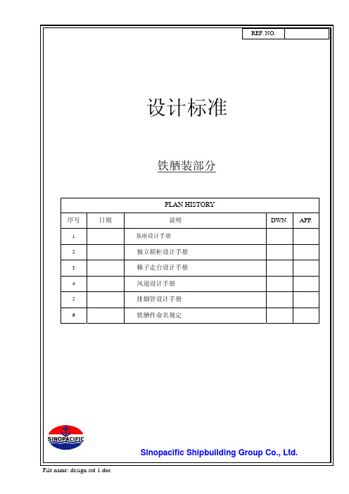
PAGE NO. 2REF. NO目录DATE 序号DESCRIPTION 页次1 设计标准(基座设计手册) 3 - 132 设计标准(独立箱柜设计手册)14 - 153 设计标准(梯子走台设计手册)26 - 414 设计标准(风道设计手册)42 - 615 设计标准(排烟管设计手册)62 - 736 STRUCTURE NAME 制定规定 74 - 81File name: design std-1.doc1. 考虑到振动,下列的主机和辅助机械,在船体设计当中主要依赖于基座设置。
DATE4. 对于基座的加强筋的设置,应延长加固到强结构构件。
5.除去特殊情况以外,角钢的螺栓孔距离如下所示.6. 下列主机和辅机除图中已标记外,螺栓孔应随着螺栓直径的使用改变如下:螺栓尺寸 螺栓孔 螺栓尺寸 螺栓孔 M6 7Ø (M22) 25 ØM8 9.5 Ø M24 27 ØM10 12 Ø (M27) 30 ØM12 14 Ø M30 33 Ø (M14) 17 Ø (M33) 37 ØM16 19 Ø M36 39 ØM20 23 Ø M42 45 ØL L1 L250 30 2065 35 3075 45 30100 55 45130 70 60150 80 707. 螺栓的长度在和螺母连接以后应给出8. 所有的螺栓和螺母除了标记了制造厂图提供的特殊的材料以外 ,Q235-A 9. 下列设备安装使用单螺母,其它的用双螺母。
1)备用螺旋桨轴2-3个 螺齿2-3个 螺齿弹簧垫圈设计标准(基座设计手册)REF. NO.DATE11. 连接在舷侧的基座的支撑腿尽可能连到船体结构,同时满足船级社的要求。
12.如果是钢板形式基座,为了焊接,基座的里面应设置人孔 .13. 为使管路不碰基座,管系布置时要研讨商议,基座设计也要跟管子设计商议,然后确定。
SPD-S铁舾件设计系统操作使用说明书
SPD-S铁舾件设计系统操作使用说明书上海东欣软件工程有限公司二ΟΟ六年八月目录1标准部件输入 (2)2铁舾件处理 (3)2.1安装铁舾件操作 (3)2.2制作钢板并安装操作 (4)2.3修改铁舾件操作 (5)2.3.1重命名铁舾件操作 (5)2.3.2移动铁舾件操作 (5)2.3.3复制铁舾件操作 (5)2.3.4旋转铁舾件操作 (5)2.3.5伸缩型材操作 (5)2.3.6翻转型材操作 (6)2.3.7替换型材操作 (6)2.3.8修改参数操作 (6)2.3.9修改材质操作 (6)2.4删除铁舾件操作 (6)2.5标准模型库存取操作 (6)2.6材料清单生成操作 (7)3零件和托盘处理 (8)3.1铁舾件托盘建立 (8)3.2铁舾件零件处理 (8)3.3铁舾件托盘处理 (8)4图纸处理 (9)4.1铁舾件制作图生成 (9)4.2图号管理、图纸输出和图面处理 (9)5生产用表处理 (10)5.1铁舾件制作图生成 (10)5.2查看输出文件夹 (10)1标准部件输入在启动界面上点击参数化标准部件按扭,则可以将参数化部件库(data/hdssd.pam)中的参数化铁舾件的参数标准化,以部件代号作为选择的标示保存在标准数据库(data/vspd_std)和实体部件库(data/myspd.pel)中,以备交互布置时使用。
标准部件输入对话框如下:在标准部件输入对话框中先选择大类,确定大类后,再选择小类,然后再选择参数类型。
选择相关的工程目录,则保存到工程部件库(工程编号.PEL)中,如果要保存到系统部件库(myspd.PEL)中,则选择EFCSD目录即可。
在下面的表格中输入部件代号以及与该代号相关联的参数值,点击保存按扭即可。
参数名称的意义可查看PPD.exe。
如需要输入多行标准部件,点击添加按钮,系统自动增加部件输入的空白项,供用户进行部件的输入。
如果要删除部件,只要删除该部件代号,然后再按保存按钮即可。
FRC-K、D系列金属设计的服务单元产品说明书

Service units FRC-K, D seriesService units FRC-K, D series, metal designProduct range overview – Service unit components, D series, metal2d Internet: /catalogue/...Subject to change – 2022/03Service units FRC-K, D series, metal design Product range overview – Service unit components, D series, metal3 2022/03 – Subject to change d Internet: /catalogue/...Service units FRC-K, D series, metal designProduct range overview – Service unit components, D series, metal4d Internet: /catalogue/...Subject to change – 2022/03Service units FRC-K, D series, metal design Product range overview – Service unit components, D series, metal5 2022/03 – Subject to change d Internet: /catalogue/...Service units FRC-K, D series, metal designProduct range overview6d Internet: /catalogue/...Subject to change – 2022/03Service units FRC-K, D series, metal design Peripherals overviewH--NoteThe range of accessories depends onthe service unit selected. The exam-ple shows service unit FRC-KF.Range of accessoriesa Peripherals pages of the individu-al devices7 2022/03 – Subject to change d Internet: /catalogue/...Service units FRC-K, D series, metal designType codes8d Internet: /catalogue/...Subject to change – 2022/03Service units FRC-KA, D series, metal design Datasheet FRC-KAFunctionWith condensate drainWith condensate drain• Filter regulator LFR • Branching module FRM • Lubricators LOE• Mounting accessories -M-Flow rate650 ... 8200 l/min-Q-Temperature range–10 ... +60°C-L-Operating pressure1 ... 16 bar(0.1 ... 1.6 MPa)• For lubricated and unlubricatedcompressed air• Two connections for unlubricatedcompressed air supply• One connection for lubricated com-pressed air supply• New filter cartridges a page 34MaxiG1/2G1/21) With FRC-...-D-DI.-H-Note: This product conforms to ISO 1179-1 and ISO 228-1.1) Measured at p1 = 10 bar (1 MPa), p2 = 6 bar (0.6 MPa) and Δp = 1 bar (0.1 MPa).2) With FRC-...-D-DI.-H-125 l/min must be available for the fully automatic condensate drain to close correctly.9 2022/03 – Subject to change d Internet: /catalogue/...Service units FRC-KA, D series, metal designDatasheet FRC-KA1) Corrosion resistance class CRC 2 to Festo standard FN 940070Moderate corrosion stress. Indoor applications in which condensation can occur. External visible parts with primarily decorative surface requirements which are in direct contact with a normal industrial environment.1) With FRC-...-D-DI.-NoteH-Materials a Datasheet for the indi-vidual devicesStandard flow rate qn as a function of output pressure p2FRC-1/2-D-DI-MAXI-KA(-A)Primary pressure p1 = 10 bar (1 MPa)10d Internet: /catalogue/...Subject to change – 2022/03-H-Note: This product conforms to ISO 1179-1 and ISO 228-1.FunctionWith condensate drainManualWith condensate drainFully automatic• Filter regulator LFR• Branching module FRM with pres-sure switch• Lubricators LOE• Mounting accessories -M-Flow rate650 ... 8200 l/min-Q-Temperature range–10 ... +60°C-L-Operating pressure1 ... 16 bar(0.1 ... 1.6 MPa)• Electrical pressure monitoring withadjustable switching pressure• For lubricated and unlubricatedcompressed air• One connection for unlubricatedcompressed air supply• One connection for lubricated com-pressed air supply• New filter cartridges a page 34MaxiG1/2G1/21) With FRC-...-D-DI.-H-Note: This product conforms to ISO 1179-1 and ISO 228-1.1) Measured at p1 = 10 bar (1 MPa), p2 = 6 bar (0.6 MPa) and Δp = 1 bar (0.1 MPa).2) With FRC-...-D-DI.-H-125 l/min must be available for the fully automatic condensate drain to close correctly.1) Corrosion resistance class CRC 2 to Festo standard FN 940070Moderate corrosion stress. Indoor applications in which condensation can occur. External visible parts with primarily decorative surface requirements which are in direct contact with a normal industrial environment.1) With FRC-...-D-DI.-NoteH-Materials a Datasheet for the indi-vidual devicesStandard flow rate qn as a function of output pressure p2FRC-1/2-D-DI-MAXI-KB(-A)Primary pressure p1 = 10 bar (1 MPa)-H-Note: This product conforms to ISO 1179-1 and ISO 228-1.FunctionWith condensate drainManualWith condensate drainFully automatic• On/off valve HE, manually operated • Filter regulator LFR• Branching module FRM with pres-sure switch• Lubricators LOE• Mounting accessories -M-Flow rate640 ... 7800 l/min-Q-Temperature range–10 ... +60°C-L-Operating pressure1 ... 16 bar(0.1 ... 1.6 MPa)• An additional quick exhaust valve isrequired at the service unit outletfor safe exhausting of the system• Electrical pressure monitoring withadjustable switching pressure• The system is exhausted when it isswitched off• For lubricated and unlubricatedcompressed air• One connection for unlubricatedcompressed air supply• One connection for lubricated com-pressed air supply• New filter cartridges a page 34Maxi1) With FRC-...-D-DI.-H-Note: This product conforms to ISO 1179-1 and ISO 228-1.1) Measured at p1 = 10 bar (1 MPa), p2 = 6 bar (0.6 MPa) and Δp = 1 bar (0.1 MPa).2) With FRC-...-D-DI.-H-125 l/min must be available for the fully automatic condensate drain to close correctly.1) Corrosion resistance class CRC 2 to Festo standard FN 940070Moderate corrosion stress. Indoor applications in which condensation can occur. External visible parts with primarily decorative surface requirements which are in direct contact with a normal industrial environment.1) With FRC-...-D-DI.-NoteH-Materials a Datasheet for the indi-vidual devicesStandard flow rate qn as a function of output pressure p2FRC-1/2-D-DI-MAXI-KC(-A)Primary pressure p1 = 10 bar (1 MPa)-H-Note: This product conforms to ISO 1179-1 and ISO 228-1.FunctionWith condensate drainManualWith condensate drainFully automatic• Filter regulator LFR• Lubricators LOE• On/off valve HEE, electrically actuat-ed, 24 V DC• Soft-start valve HEL, pneumatically actuated• Mounting accessories -M-Flow rate550 ... 3800 l/min-Q-Temperature range–10 ... +60°C-L-Operating pressure3 ... 16 bar(0.3 ... 1.6 MPa)• Gradual pressure build-up atswitch-on prevents sudden, unpre-dictable movements• When the unit is switched off, quickexhausting ensures rapid pressurereduction• For lubricated compressed air• New filter cartridges apage 341) With FRC-...-D-DI.-H-Note: This product conforms to ISO 1179-1 and ISO 228-1.1) Measured at p1 = 10 bar (1 MPa), p2 = 6 bar (0.6 MPa) and Δp = 1 bar (0.1 MPa).2) With FRC-...-D-DI.-H-125 l/min must be available for the fully automatic condensate drain to close correctly.1) Corrosion resistance class CRC 2 to Festo standard FN 940070Moderate corrosion stress. Indoor applications in which condensation can occur. External visible parts with primarily decorative surface requirements which are in direct contact with a normal industrial environment.1) With FRC-...-D-DI.-NoteH-Materials a Datasheet for the indi-vidual devicesStandard flow rate qn as a function of output pressure p2FRC-1/2-D-DI-MAXI-KE(-A)Primary pressure p1 = 10 bar (1 MPa)-H-Note: This product conforms to ISO 1179-1 and ISO 228-1.Service units FRC-KF, D series, metal design Datasheet FRC-KFFunctionWith condensate drainManualWith condensate drainFully automatic• On/off valve HE, manually operated • Filter regulator LFR• Lubricators LOE• On/off valve HEE, electrically actuat-ed, 24 V DC• Soft-start valve HEL, pneumatically actuated• Branching module FRM with pres-sure switch• Mounting accessories -M-Flow rate530 ... 6000 l/min-Q-Temperature range–10 ... +60°C-L-Operating pressure3 ... 16 bar(0.3 ... 1.6 MPa)• Gradual pressure build-up atswitch-on prevents sudden, unpre-dictable movements• An additional quick exhaust valve isrequired at the service unit outletfor safe exhausting of the system• For lubricated compressed air• Two branch connections are availa-ble• Supply pressure can be opened andclosed• New filter cartridges apage 341) With FRC-...-D-DI.-H-Note: This product conforms to ISO 1179-1 and ISO 228-1.1) Measured at p1 = 10 bar (1 MPa), p2 = 6 bar (0.6 MPa) and Δp = 1 bar (0.1 MPa).2) With FRC-...-D-DI.-H-125 l/min must be available for the fully automatic condensate drain to close correctly.Service units FRC-KF, D series, metal designDatasheet FRC-KF1) Corrosion resistance class CRC 2 to Festo standard FN 940070Moderate corrosion stress. Indoor applications in which condensation can occur. External visible parts with primarily decorative surface requirements which are in direct contact with a normal industrial environment.1) With FRC-...-D-DI.-NoteH-Materials a Datasheet for the indi-vidual devicesStandard flow rate qn as a function of output pressure p2FRC-1/2-D-DI-MAXI-KF(-A)Primary pressure p1 = 10 bar (1 MPa)Service units FRC-KF, D series, metal design Datasheet FRC-KF-H-Note: This product conforms to ISO 1179-1 and ISO 228-1.Service unit combinations FRC-K, D series, polymer designProduct range overview – Service unit components, D series, polymerService unit combinations FRC-K, D series, polymer design Product range overview – Service unit components, D series, polymerService unit combinations FRC-K, D series, polymer designPeripherals overview12H- - NoteThe range of accessories depends on the service unit combination select-ed. The example shows the serviceunit combination FRC-KC.Service unit combinations FRC-K, D series, polymer designType codesService unit combinations FRC-KA, D series, polymer design Datasheet FRC-KAFunction• Filter regulating valve • Distributor module • Lubricators -M-Standard nominal flow rate700 l/min-Q-Temperature range–5 ... +50°C-L-Operating pressure1.5 ... 10 bar(0.15 ... 1 MPa)• For filtered and lubricated com-pressed air• Output pressure is infinitely adjust-able within the pressure regulation range • Removal of filtered and unlubricatedcompressed air at the distributormodule ports• New filter cartridges a page 34The following oils are recommendedfor Festo components:Viscosity range toISO 3448 class VG 3232 mm2/s (cSt) at 40°CApproved oils:• Festo special oil a page 34• ARAL Vitam GF 32• BP Energol HLP 32• Esso Nuto H 32• Mobil DTE 24• Shell Tellus Oil DO 32 Output pressure constant, without primary pressure compensation, with return flow, with secondary exhausting1) Measured at p1 = 10 bar (1 MPa), p2 = 6 bar (0.6 MPa) and Δp = 1 bar (0.1 MPa).H--NoteMinor leakage at the output is in-tended by design. It improves thecontrol behaviour of the regulatorwhich is not compensated for inputpressure.In rare cases, however, the leakagecan be up to 500 l/h.Service unit combinations FRC-KA, D series, polymer design Datasheet FRC-KA1) Corrosion resistance class CRC 1 to Festo standard FN 940070Low corrosion stress. Dry internal application or transport and storage protection. Also applies to parts behind covers, in the non-visible interior area, or parts which are covered in the application (e.g. drive trunnions).Standard flow rate qn as a function of output pressure p2FRC-1/4-DB-7-MINI-KAInput pressure p1 = 10 bar (1 MPa)Service unit combinations FRC-KA, D series, polymer design Datasheet FRC-KAService unit combinations FRC-KC, D series, polymer design Datasheet FRC-KCFunction• Manually operated on/off valve • Filter regulating valve• Distributor module• Lubricators -M-Standard nominal flow rate400 l/min-Q-Temperature range–5 ... +50°C-L-Operating pressure1.5 ... 10 bar(0.15 ... 1 MPa)• For filtered and lubricated com-pressed air• The operating pressure can be switched on or off• Output pressure is infinitely adjust-able within the pressure regulation range • The unit is exhausted whenswitched off• Removal of filtered and unlubricatedcompressed air at the distributormodule ports• New filter cartridges a page 34The following oils are recommendedfor Festo components:Viscosity range toISO 3448 class VG 3232 mm2/s (cSt) at 40°CApproved oils:• Festo special oil a page 34• ARAL Vitam GF 32• BP Energol HLP 32• Esso Nuto H 32• Mobil DTE 24• Shell Tellus Oil DO 32 Output pressure constant, without primary pressure compensation, with return flow, with secondary exhausting1) Measured at p1 = 10 bar (1 MPa), p2 = 6 bar (0.6 MPa) and Δp = 1 bar (0.1 MPa).H--NoteMinor leakage at the output is in-tended by design. It improves thecontrol behaviour of the regulatorwhich is not compensated for inputpressure.In rare cases, however, the leakagecan be up to 500 l/h.31 2022/03 – Subject to change d Internet: /catalogue/...32d Internet: /catalogue/...Subject to change – 2022/03Service unit combinations FRC-KC, D series, polymer designDatasheet FRC-KC1) Corrosion resistance class CRC 1 to Festo standard FN 940070Low corrosion stress. Dry internal application or transportand storage protection. Also applies to parts behind covers, in the non-visible interior area, or parts which are covered in the application (e.g. drive trunnions).Standard flow rate qn as a function of output pressure p2FRC-1/4-DB-7-MINI-KCInput pressure p1 = 10 bar (1 MPa)Service unit combinations FRC-KC, D series, polymer design Datasheet FRC-KC33 2022/03 – Subject to change d Internet: /catalogue/...Service units FRC-K, D seriesAccessoriesFilter cartridges, D series, metalFilter cartridges, D series, polymerSpecial oil34d Internet: /catalogue/...Subject to change – 2022/03Service units FRC-K, D series Accessories35 2022/03 – Subject to change d Internet: /catalogue/...Festo - Your Partner in AutomationConnect with us/socialmedia 1Festo Inc.2Festo Pneumatic 3Festo Corporation 4Regional Service Center 5300 Explorer DriveMississauga, ON L4W 5G4CanadaAv. Ceylán 3,Col. Tequesquináhuac 54020 Tlalnepantla, Estado de México1377 Motor Parkway Suite 310Islandia, NY 117497777 Columbia Road Mason, OH 45040Festo Customer Interaction CenterTel:187****3786Fax:187****3786Email:*****************************Multinational Contact Center 01 800 337 8669***********************Festo Customer Interaction Center180****3786180****3786*****************************S u b j e c t t o c h a n g e。
舾装件安装作业指导书
文件修改记录版次 修改原因 修改内容 修改人/日期 批准人/日期1目的为了更好的加强舾装件安装管理,规范舾装件安装流程,确保对工程的需要特制定本作业指导书2适用范围适用于机电工区舾装件安装及管理。
3定义和术语(无)4涉及岗位工程主管、作业长、工艺员、质量检验员、安全员、施工班组5职责5.1工程主管对舾装件的安装、进度、质量、安全环保负责,工程主管负责对施工前的交底,施工过程中的工艺执行进行确认,组织交验,必检项目提交项目质量主管5.2 作业长负责协助铁舾装主管管辖单项目生产过程的协调工作、生产前的准备、安生产和施工质量工作。
5.3 工艺员负责提供图纸、工艺、焊接程序,负责基准点及工序控制点的指导和确认 5.4 质量检查员协助主管组织项目报检和试验的提交工作;跟踪产品质量检查和控制,上报产品整体质量情况;对产品质量检查和控制根据在现场发现的质量问题通过信息反馈系统通知相关部门,跟踪落实情况,保证反馈信息的及时闭环完成工作。
5.5 工区安全员负责对施工过程中的安全隐患及不安全行为、状态及时提出、制止, 落实整改措施。
5.6 施工班组负责所承接该舾装工程满足工艺、精控、安全、质量进度要求5作业程序6.1 工程主管根据生产计划布置生产任务,对施工的队伍进行专项的交底,熟悉整个工程的流程及作业指导书的相关要求。
6.1.1 从事焊割作业的人员应持证上岗(明火操作证),焊工须持船级社焊工证书,并按公司焊割作业要求施工。
6.1.2 焊条要存放在保温桶内,并通电保温。
6.2 安装程序及要求6.2.1.1要充分理解图纸后方可施工,如图纸有疑问不可盲目操作,要与工艺核对后再安装施工。
6.2.1.2装配过程中要注意做到横平竖直,尺寸要与图纸相符,左右舷是否对称,同时也要注意反变形控制,减少后续校正工作量。
6.2.1.3 坡口的开设必须按照图纸要求。
开好坡口后必须打磨干净。
6.2.1.4 安装施工人员要做好自检、互检,严格遵守“三级报验”制度,在自检合格基础上填写《舾装件安装质量交验单》,向质量部主管交验。
SIWAREX JB 钢铁锈防爆规格权重系统操作说明说明书

Weighing systemsSIWAREX JB stainless steel with ATEX certificateCompact Operating InstructionsLegal information Warning notice systemThis manual contains notices you have to observe in order to ensure your personal safety, as well as to prevent damage to property. The notices referring to your personal safety are highlighted in the manual by a safety alert symbol, notices referring only to property damage have no safety alert symbol. These notices shown below aregraded according to the degree of danger.DANGERindicates that death or severe personal injury will result if proper precautions are not taken.WARNINGindicates that death or severe personal injury may result if proper precautions are not taken.CAUTIONwith a safety alert symbol, indicates that minor personal injury can result if proper precautions are not taken.CAUTIONwithout a safety alert symbol, indicates that property damage can result if proper precautions are not taken.NOTICEindicates that an unintended result or situation can occur if the corresponding information is not taken into account.If more than one degree of danger is present, the warning notice representing the highest degree of danger willbe used. A notice warning of injury to persons with a safety alert symbol may also include a warning relating to property damage.Qualified PersonnelThe product/system described in this documentation may be operated only by personnel qualified for the specific task in accordance with the relevant documentation for the specific task, in particular its warning notices and safety instructions. Qualified personnel are those who, based on their training and experience, are capable of identifying risks and avoiding potential hazards when working with these products/systems.Proper use of Siemens productsNote the following:WARNINGSiemens products may only be used for the applications described in the catalog and in the relevant technical documentation. If products and components from other manufacturers are used, these must be recommended or approved by Siemens. Proper transport, storage, installation, assembly, commissioning, operation andmaintenance are required to ensure that the products operate safely and without any problems. The permissible ambient conditions must be adhered to. The information in the relevant documentation must be observed.TrademarksAll names identified by ® are registered trademarks of the Siemens AG. The remaining trademarks in thispublication may be trademarks whose use by third parties for their own purposes could violate the rights of the owner.Disclaimer of LiabilityWe have reviewed the contents of this publication to ensure consistency with the hardware and software described. Since variance cannot be precluded entirely, we cannot guarantee full consistency. However, the information in this publication is reviewed regularly and any necessary corrections are included in subsequent editions.Siemens AG Industry Sector Postfach 48 4890026 NÜRNBERG A5E01257284C-01 Ⓟ 07/2010 Copyright © Siemens AG 2010. Technical data subject to changeTable of contents1 Introduction (4)1.1 Purpose of this documentation (4)1.2 History (4)1.3 Trademarks (4)1.4 Environmental protection (4)2 Notes on handling the product (5)3 Description (7)3.1 Applications (7)3.2 Properties (8)3.3 Design (8)4 Application planning (10)4.1 Alternative EMC cable glands (10)4.2 Selection of suitable cables (10)5 Installing and connecting (12)5.1 Qualified personnel (12)5.2 Mounting (12)5.3 Connecting principle (13)5.4 Connection (15)5.4.1 Installing the EMC cable glands and the screw plugs (15)5.4.2 Connecting the shielding (16)5.4.3 Installing the spring-loaded terminal block in the enclosure (16)5.4.4 Connecting spring-loaded terminals (17)5.4.5 Screwing on the cover (18)6 Technical data (19)6.1 Ambient conditions (19)6.2 Mechanical and electrical data (19)6.3 Explosion protection (20)6.4 Electromagnetic compatibility (20)6.5 Dimension drawing (21)7 Ordering data (22)7.1 Order no (22)7.2 Accessories (22)A Appendix (23)A.1 Technical support (23)SIWAREX JB stainless steel with ATEX certificateIntroduction 1 1.1Purpose of this documentationThese instructions contain all the information you need for commissioning and using thedevice.They are directed at persons who mechanically assemble, connect, start up, and use thedevice.1.2HistoryThe following versions of this documentation have been released to date. The changes applyto the previous version:Edition Comment / change06/2010 Initial release1.3TrademarksSIWAREX ® is a registered trademark of Siemens AG.All other names appearing in these instructions may be trademarks whose use by thirdparties for their own purposes may infringe upon owners rights.1.4Environmental protectionDevices described in this programming manual can be recycled owing to the low content ofnoxious substances in their version. Please contact a certified waste disposal company foreco-friendly recycling and to dispose of your old devices.SIWAREX JB stainless steel with ATEX certificateNotes on handling the product 2Proper usageProper usage means that this product must only be used within the scope of the technicalspecifications and intended purposes of these operating instructions.If this device is used properly in compliance with the safety notices, this device will notpresent any danger.This device can only function correctly and safely if it is transported, stored, set up andmounted correctly.Correct operation of the device must be ensured by complying with the technicalspecifications.Improper handling can result in death, personal injury or property damage.Notes on liability for defectsWe expressly point out that the product quality is exclusively and conclusively described inthe sales contract. The content of this product documentation is neither part of a previous orexisting agreement, promise or legal relationship, nor is it intended to modify these. Allobligations on the part of Siemens AG are contained in the respective sales contract, whichalso contains the complete and solely applicable liability provisions. The provisions definedin the sales contract for the responsibility for defects are neither extended nor limited by theremarks in this document.Delivery informationThe current scope of delivery is listed on the shipping documents enclosed with the deliveryin accordance with the valid sales contract.When opening the packaging, please observe the relevant information. Check the deliveryfor completeness and undamaged condition. In particular, the order number on the ratingplate must be compared to the ordering data.Before you start work, please read these operating instructions. They contain importantinformation and data whose observation ensures the general safety and functionality of thisdevice. The manual will help you to handle this product more easily and efficiently, allowingyou to achieve reliable measuring results.SIWAREX JB stainless steel with ATEX certificateNotes on handling the productSIWAREX JB stainless steel with ATEX certificateQualified personnelIn the context of this documentation, qualified personnel are people who are familiar with the installation, mounting, commissioning, and operation of the product. These people must have the following qualifications:● They must be trained, instructed and authorized to operate and maintain devices and systems in accordance with their place of work and in compliance with the safety engineering standards for – Electrical circuits – High pressures– Corrosive and hazardous media● They must be trained, instructed and authorized to maintain and use appropriate safety equipment according to the standards for safety engineering. ● In the case of devices with explosion protection, qualified persons must be trained, instructed and authorized to perform work on electrical circuits in plants subject to explosion hazards.Important notes on connectingWARNINGElectric shockThe SIWAREX JB junction box must only be used with extra-low voltages ≤ 30 V.Important notes on cleaningCAUTIONMalfunctionDo not subject the junction box directly to the jet from a high-pressure cleaner.Explosion protectionWARNINGDanger of explosionObserve the test certificates, provisions and laws applicable in your country during connection, assembly and operation. For hazardous areas, these are for example: • IEC 60079-14 (international)• EN 60079-14 (previously VDE0165, T1) (EU, Germany) • The operational safety directive (Germany)All work undertaken on electrical circuits in hazardous areas must only be performed by skilled personnel.Description 3 3.1ApplicationsField of applicationThe stainless steel SIWAREX JB junction box is used in weighing systems with extra-lowvoltages ≤ 30 V.The junction box can connect up to four load cells to the weighing module at the same time.Operating principleLoad cells with 4-wire and 6-wire strain gauges can be connected.The cable connection from the junction box to the weighing module is implemented with a 6-wire cable.LC Load cellJB SIWAREX JB junction boxW Weighing moduleFigure 3-1 Principle of applicationSIWAREX JB stainless steel with ATEX certificate3.2 Properties3.2PropertiesThe SIWAREX JB junction box has the following properties:●It consists of stainless, acid-resistant steel 1.4301.●It is protected against dust and jet water according to protection class IP66.●The junction box is maintenance-free.●The cables are fed into the junction box via EMC cable glands.–The cable glands are made of nickel-plated brass.–Unneeded openings for cable glands are sealed with a cap screw.●Electromagnetic compatibility:Installing the shield in the cable glands provides a high degree of protection againstinterference.3.3DesignSIWAREX JB stainless steel with ATEX certificate①Cover②Screw for cover (4x)③Rear side with nameplate and ATEX plate④Lower part⑤Support for mounting⑥EMC cable glandFigure 3-2 DesignSIWAREX JB stainless steel with ATEX certificate3.3 DesignSIWAREX JB stainless steel with ATEX certificateNameplateThe nameplate shows the order number and other important product information.The following example explains the information on the nameplate.① Product name ② Degree of protection③ Consult operating instructions ④ Development stage ⑤ Manufacturer ⑥ Country of origin ⑦ Serial number ⑧Order no.Figure 3-3NameplateATEX plate①Certification data in accordance with ATEXFigure 3-4ATEX plateSIWAREX JB stainless steel with ATEX certificateApplication planning44.1 Alternative EMC cable glandsIf you need stainless steel EMC cable glands, you can purchase them from corresponding suppliers. Please note that the cable glands must be approved for the respective applications. See Service and support(/automation/service&support )Note4.2Selection of suitable cablesSignal cableThe junction box is connected to the weighing module by means of a signal cable. Use a shielded cable with six cores as the signal cable. We recommend the SIWAREX cable Li2Y2x0.75St+2x(2x0.34St)-CY:● For standard applications: 7MH4702-8AG, orange sheath color.● For intrinsically safe Ex applications: 7MH4702-8AF, light blue sheath color.The cables and lines must correspond to the installation regulations according to EN 60079-14. In hazardous areas, the diameter of individual conductors must not be smaller than 0.1 mm.WARNINGShort circuit/explosion hazardAt an ambient temperature T ≥ 60 °C, use heat-resistant cables which are approved for an ambient temperature at least 20 K higher.NoteThe maximum cable length between the load cell and the weighing module is stated in the weighing module documentation.Application planning4.2 Selection of suitable cablesSuitable cables for spring-loaded terminalsThe following cables are suitable for connecting to the spring-loaded terminalsCross section Design0.08 ... 1.5 mm² AWG 28 ... 16 •Solid•Stranded•Finely-stranded - with galvanized individual wires •Finely-stranded - compacted strands•Finely-stranded with gas-tight crimped-on pin cable lug0.08 ... 1 mm²AWG 28 (18)•Finely-stranded with gas-tight crimped-on end sleevesCAUTIONShort-circuitUse end sleeves for small conductor cross-sections.Otherwise the stripped litz wire may buckle when it is inserted into the terminal. In this case,the line is clamped onto the insulation, which will cause contact problems.Load cell cablesDMS load cells are supplied with connecting cables.Connecting a PAL cableFor non-intrinsically safe use of the junction box, a PAL cable must be connected. An M6x12bolt is provided for this on the mounting flange. The PAL cable must be protected againstbecoming loose on its own, which is achieved by a cable eye crimped to the cable.WARNINGDanger of explosionPlease observe that in the case of shielded cables of intrinsically safe circuits in hazardousareas, only one grounding is permissible.If grounding is to be on both sides, an equipotential bonding conductor with at least 4 mm²must be connected.Installing and connecting 5WARNINGDanger of explosionObserve the test certificates, provisions and laws applicable in the country of operationduring connection, assembly, and operation.For hazardous areas in Europe, for example, this is EN 60079-14.5.1Qualified personnelThe SIWAREX JB junction box must only be mounted and connected by qualified personnel.5.2MountingYou can mount the SIWAREX JB junction box in any position. Preferrably, the cable glandsshould point downward.1.Prepare the location for mounting. Position the corresponding drill holes, see Dimensiondrawing (Page 21).2.Screw the junction box tight with four screws.5.3 Connecting principle 5.3Connecting principleLoad cells with four-wire system1.Connect the load cells to the weighing module according to the circuit diagram.2.Install the following jumpers:Jumper From terminal To terminal1 EXC SENSE2 EXC+ SENSE+NOTICEIf the jumpers are missing, the weighing module will report a wire break.5.3 Connecting principleLoad cells with six-wire systemConnect the load cells to the weighing module according to the circuit diagram.1.6 VKLHOG FRQQHFWLRQ HOHPHQWFigure 5-2 Connecting principle for load cells with six-wire system5.4 Connection 5.4Connection5.4.1Installing the EMC cable glands and the screw plugsLC Input for the connecting cable of a load cellW Output to the weighing module or to the "Ex barrier"PAL Equipotential bonding conductorFigure 5-3 Assignment of the cable glands1.Install an EMC cable gland for each load cell that is to be connected. The position of thecable glands is shown in the figure above.2.Open the cover of the junction box.3.Close any unused openings in the SIWAREX JB enclosure using a cap screw.WARNINGMeasurement inaccuracies/risk of explosionThe cables must be matched to the cable glands.If you use the provided M16x1.5 cable glands, only cables with a diameter of 7 to 12mm may be laid into the device.After installation, make sure that the cables are positioned securely and that the sealsare in the correct position.5.4 Connection5.4.2Connecting the shielding1.Connect the cable shielding in the EMC cable glands so that it covers a broad area.Figure 5-4 Connecting the shielding in the EMC cable gland5.4.3Installing the spring-loaded terminal block in the enclosureFigure 5-5 Mounting the spring-loaded terminal block on the mounting rail1.Tighten the two screws on the mounting rail by one turn each.2.Slide the spring-loaded terminal block on one side under the applied screw ①.3.Insert the spring-loaded terminal block ②.4.Screw the spring-loaded terminal block firmly into place.5.4 Connection5.4.4 Connecting spring-loaded terminals(;&6,* 6(16( 6(16(6,*(;&Figure 5-6Pin assignment of the spring-loaded terminalsIn order to connect the spring-loaded terminals, you require a screwdriver with a maximum blade width of 2.5 mm.1. Strip the insulation from the cables as shown.Figure 5-7 Strip cable2. Push the screwdriver into the rectangular opening ①. This opens the spring clip of the spring-loaded terminal.Figure 5-8 Connection of spring-loaded terminals3. Insert the stripped wire into the round opening as far as the stop ②.4. Remove the screwdriver from the rectangular opening ③.The spring clip firmly holds the stripped wire and establishes the contact.The use of spring-loaded terminals ensures that the contact pressure being exerted is permanently maintained.NoteThe use of spring-loaded terminals ensures that the contact pressure being exerted is permanently maintained.5.4 Connection5.4.5Screwing on the coverRequirementsCAUTIONLoss of degree of protectionPrior to closing the cover, check to ensure that:•No dirt or cable residues are in the enclosure.Such residues could lead to faults or short-circuits.•The sealing surfaces are clean.•The necessary cable glands are installed and screwed tightly in place.•Unused openings are closed using the supplied screw plugs.WARNINGLoss of degree of protectionDegree of protection IP66 is only guaranteed if the device was installed perfectly.Please note that if the device is open or not completely closed, this degree of protection isno longer guaranteed.Procedure1.Place the cover and screw it on properly.Technical data 6 6.1Ambient conditionsAmbient condition ValueAmbient temperature - 50 °C ... + 80 °CStorage temperature - 50 °C ... + 100 °CType of protection: IP66, DIN 605296.2Mechanical and electrical dataEnclosure material Stainless steel 1.4301Weight Approx. 1.5 kgColor Polished stainless steelElectrical connection Spring-loaded terminals 1.5/1 mm2Cable glands •Load cells •Signal cable Screw connectionM16 x 1.5 mmM20 x 1.5 mmTerminal area5 ... 7 mm7 ... 12 mmVibration test of the terminals Acc. to DIN EN 60068-2-6: 1996-0510 ... 150 ... 10 Hz, amplitude 0.35 mmVariable ValueRated voltage max. AC 250 VRated current max. 10 A per terminalConductor cross-section max. 1.5 mm²Technical data6.3 Explosion protection6.3Explosion protectionIn hazardous areas, it is only permitted to use components with the appropriate Ex approval.The junction box can be used in hazardous areas even for connecting an intrinsically safecircuit according to EN 60079-14 or EN 61241-14.In zone 20, certified circuits in category ia, ib or iaD, ibD are permitted.The terminals meet the requirements for disconnecting intrinsically safe circuits: Thecreepage distance and clearance are greater than 8 mm.Only connect the device to circuits that comply with the technical data specified on thenameplate or on the certificates and approvals (e.g., the EC-type examination certificates). Ifthe circuits do not comply with the information in the certificates and approvals, then thesafety required for the approval is longer guaranteed.When using the junction box for type of protection nA, the junction box must be included inthe local potential equalization. The external and internal connection in the cover must beused for this purpose. Use a cable eye that is crimped to the cable to do this. The minimumcross-section of the PAL connecting cable must be the same or greater than the cross-section of the phase conductor. The washer that is also to be used must ensure that thecontact pressure is permanently maintained. The four cover screws must be screwed tight.Before loosening the cover screws, all of the circuits must be de-energized.The circuits that are connected must be either only intrinsically safe or only non-intrinsicallysafe. Mixing is not allowed.If the SIWAREX JB junction box is operated with the markingII 1 D Ex tb + ib IIIC T85°C Da IP66 in hazardous zone 20, then the feeding circuit mustmeet the requirements of protection type "intrinisically safe" Cat. ia or Cat. ib in connectionwith another recognized protection type.6.4Electromagnetic compatibilityThe SIWAREX JB junction box meets the following EMC requirements:●EN 61326: 1999●EN 45501: 1992●NAMUR NE21: 2004To maintain the electromagnetic compatibility, for example,●ensure that the cables are routed with electromagnetic compatibility (even withincabinets!).●lay the signal cable segregated from cables with voltages > 60 V or high currents.●avoid sites neighboring large electrical systemsTechnical data6.5 Dimension drawing6.5Dimension drawingFigure 6-1Dimension drawingOrdering data 7 7.1Order no.Junction boxDesignation Order no.7MH4710-1EA01SIWAREX JB stainless steel with ATEXcertificate7.2AccessoriesEMC cable glands, stainless steelRecommended suppliers:RST Rabe-System-Technik und Vertriebs-GmbHOtto-Lilienthal-Str. 1949134 WallenhorstGermanyPhone: +45 (0) 54 07 / 87 66 – 0Fax: +45 (0) 54 07 / 87 66 – 98Internet: RST in the Internet ()Signal cableRecommended cable:SIWAREX cable Li2Y2x0.75St+2x(2x0.34St)-CYApplication Sheath color Order no.Standard applications Orange 7MH4702-8AGIntrinsically safe Ex application Light blue 7MH4702-8AFAppendix A A.1Technical supportTechnical SupportYou can contact Technical Support for all IA and DT products:●Via the Internet using the Support Request:Support request (/automation/support-request)●E-mail (mailto:******************************)●Phone: +49 (0) 180 5050 222(0.14 €/min on German landlines, prices may vary for mobile systems)●Fax: +49 (0) 180 5050 223(0.14 €/min on German landlines, prices may vary for mobile systems)Further information about our technical support is available in the Internet atTechnical Support (/automation/csi/service)Service & Support on the InternetIn addition to our documentation, we offer a comprehensive knowledge base online on theInternet at:Services & Support (/automation/service&support)There you will find:●The latest product information, FAQs, downloads, tips and tricks.●Our newsletter, providing you with the latest information about your products.● A Knowledge Manager to find the right documents for you.●Our bulletin board, where users and specialists share their knowledge worldwide.●You can find your local contact partner for Industry Automation and Drives Technologiesin our partner database.●Information about field service, repairs, spare parts and lots more under "Services."Additional SupportPlease contact your local Siemens representative and offices if you have any questionsabout the products described in this manual and do not find the right answers.Find your contact partner at:Partner (/partner)A signpost to the documentation of the various products and systems is available at:Documentation (/weighing/documentation)AppendixA.1 Technical support。
机装铁舾件

前 言为了提高设计质量和效率,适应公司快速造船和标准化造船的要求,在公司领导的倡导、支持下,设计部组织开展了《设计标准手册》的编写。
通过全体参编人员的共同努力和有关部门的大力配合,《设计标准手册》已完成编制并正式出版。
在本《设计标准手册》编制中,结合公司的生产设计实际,吸收了GB、CB和公司企业标准的适用内容。
在编制形式和深度上参照了韩国HANA的设计标准《Design Standard》,以图形和表格反映设计标准型式与工艺要求,辅以必要的文字说明。
本《设计标准手册》以公司详细设计和生产设计中正在使用的有关标准为依据,强调选编内容的统一性和实用性。
在原船体、管系、电装、船装四个分册的基础上,又增加编制了机装铁舾件分册,供各专业设计人员选用。
由于时间紧,编制较仓促,难免存在不少问题,本《设计标准手册》为试用本,请设计人员在使用中不断给予指正,将意见反馈给标准化室,(联系电话:8755),逐步补充完善本《设计标准手册》。
《设计标准手册》编委 2006年4月《设计标准手册》编委主任:黄永锡顾问:陶颖孙嘉钧杜剑锋陈罗宝章祖歧执行主任:刘建峰李高兴吴幼奇委员:陈刚徐智言何成能郭勇宋金扬《设计标准手册》(机装铁舾件分册)编写人员主编:邓荃文吴军编写人员:周熲邓荃文王章建林建中阚国强编辑:戴小虎徐玉珍8.2 布置要求1 斜梯2 直梯3 直梯安全圈3.4.2 带安全圈的直梯一般布置形式见图4 钢质踏步5 钢质拉手5.2.3 C型拉手用φ42×3.55.3.3 C型拉手的布置和安装6 机舱栏杆6.2.2.4 B16.2.2.6 C16.3.3.2 扁钢垂直固定型栏杆安装节点见图7 格栅及固定件7.2.2 格栅的制作技术要求8 平台的一般型式8.2.6 底层花钢板平台上对应双层底舱室人孔处或其附近应设置可开式花钢板,见图8.3 平台与梯子安装形式和要求9 基座9.2.2.3 考虑到结构强度9.3.2 角钢基座的设计方法9.5 螺栓、螺母、垫圈10 独立箱柜附件。
舾装件PSPC产品作业指导书
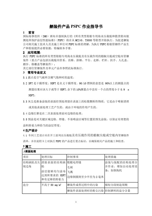
舾装件产品PSPC作业指导书1 前言国际海事组织(IMO)颁布并强制执行的《所有类型船舶专用海水压载舱和散货船双舷侧处所保护涂层性能标准》〔PSPC〕将在从MC240、T3000等船型开始执行,为促进舾装公司相关施工技术人员及施工单位对PSPC标准的理解,为执行PSPC船舶管舾件产品生产和检验提供必要依据,特编制本手册。
2 应用范围:执行PSPC标准的所有类型船舶专用海水压载舱及有压载作用的艏艉尖舱或空舱内管舾装件(重点产品包括压载舱内管系、直梯、斜梯、平台、走桥、栏杆、扶手、人孔盖、踏步、格栅盖等舾装件);其它部位管舾装件及单元产品亦参照此标准执行。
3 常用专业定义3.1露点是空气被所含潮气饱和时的温度;3.2 DFT是干膜厚度; NDFT是名义干膜厚度。
90/10惯例的意思是 90%以上的测量点的测量结果应该大于或等于NDFT,余下的10%测量点中没有一个点的厚度小于0.9 x NDFT;3.3灰尘是准备涂装的表面经预处理留在表面上的松散颗粒性物质,它是由于喷射清理或其他表面处理工艺产生的,或由于环境的作用产生的。
3.4边缘打磨是在二次表面处理前对边缘的处理;3.5预涂是对关键区域边缘、焊缝、不易喷涂区域等位置的预先涂装,以保证有理想的涂料附着力和恰当的涂层厚度;4生产设计4.1车间工艺设计应在开工前列出压载舱及有压载作用的艏艉尖舱或空舱内管舾装件清单,并在流程卡上对执行PSPC的产品进行重点标识,以确保相关产品的施工和检查。
6.1 检验事项对于检验过程中的检查部位、检查频率(范围)等事项,应按船厂、船东和涂料供应商确认的检验程序执行。
以下表格中的内容结合了PSPC要求和意见,以及行6.2检查员资质6.2.1进行涂装检验的检验员就具备:²FROSIO III级检验员资格²NACE II级检验员资格²等效资格。
6.2.2如果涂层检验员要求其他人员的协助,以在涂层检验员的监督下完成部分检验工作,这些人员的培训应使涂层检验员满意。
PZ04舾装件检验作业指导书
舾装件
文件编号 中 船 重 工 4.2 检验结果记录 舾装件检验作业指导书 ZCHI/PZ-04-09
PAGE 3/3
Q.C 按照上述的检查方法和检查基准检查,并将检查结果记录在《外购原材料、铸锻 件、机电设备、外协件到厂验收单》 ,存档,按月对检查结果进行整理分析。 4.3 检验批号编制规定
□□
中船重工船业有限公司
舾装件检验作业指导书 舾装件检验作业指导书
文件编号: 文件编号: 版 本:
受控状态 分 发 号 发放部门 持 有 者 编 审 批 制 核 准
2009 年 10 月 17 日批准
2009 年 10 月 18 日实施
重工船业有限公司发布
文件编号 中 船 重 工 舾装件检验作业指导书 ZCHI/PZ-04-09
PAGE 1/3
目录
1.目的
2.适用范围
3.检查流程
4.检查方法及检验基准
5.材料清单的接收和保管
6.质保书的保管和废止
7.解说书
修改标记
修改人
Hale Waihona Puke 修改日期文件编号 中 船 重 工 1.目的 舾装件检验作业指导书 ZCHI/PZ-04-09
PAGE 2/3
为了对我公司使用的用于产品制作的舾装件更加有效的进行质量检验和管理,特制定此 作业指导书。
□□
□□□
当月的检验批次 月份 年份
例:0703010 表示 07 年 3 月第 10 批检验 5.材料清单的接收和保管 5.1 核对入库的舾装件数量。 5.2 检查记录和材料清单保管到船舶交货后废止。 6.质保书的保管和废止 6.1 质保书应保管在品质部,每个人都能够查找文件及进行保管。 6.2 质保书至少保管三年。 7.解说书 本标准制定于 2009 年 10 月 17 日。
船舶SED电气设计系统操作使用说明书

培训教案 - 铁舾件
铁舾件培训教案一、初始化1.新建工程:新建一个文件夹,存放工程数据。
工程管理:输入工程编号、工程名称、备份目录。
2.坐标定位面:定义肋距:-10,500,1503.新建图册和模型:范围FR-10 到FR30、-20000到20000、-1000到15000特别注意:只读和整理的勾选图册建完需要保存。
图册范围根据模型范围来定义。
二、参数化标准部件:功能性介绍:将标准部件(厂标或者国标等)预先输入SPD数据库,以备建模使用。
特别注意:1.必须在打开工程的前提下输入数据。
2.数据输入好后必须按“保存”按钮,再“退出”。
3.在打开工程的情况下修改的数据无效。
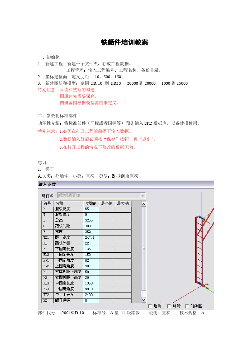
练习:1.梯子A.大类:外舾件小类:直梯类型:B型钢质直梯部件代号:4200461D-10 标准号:A型11级踏步说明:直梯技术规格:AB.大类:外舾件小类:直梯类型:加强直梯(HZ)部件代号:4200491D-10 标准号:4200495G P4 L=1120 说明:耐压直梯2.人孔盖大类:外舾件小类:水密人孔盖类型:A型埋入式人孔盖部件代号:4200201D-15 标准号:600*600-29 说明:埋入式人孔盖特别注意:标准部件输入的参数和最终生成的“铁舾件托盘管理表”中的数据对应,所以不可缺漏。
部件代号=所属图号;说明= 预舾装名称;标准号= 规格或型号。
二、铁舾件布置:在SPD 系统中自带的参数化部件布置。
练习:安装门、窗、梯子、人孔盖、高低扶手以及参数化部件。
1. 基座制作腹板高度:100 折边长度:100 复板厚度:10 折边厚度:102.小型基座3.布置梯子在fr10,7000,10000的位置布置一个B 型钢质直梯,名称为“ZT-1”。
三、栏杆自动布置功能:可以以CAD 线为栏杆的迹线(仅直线),自动布置栏杆。
L1=L2=1500 B1=B2=800C=200四、板件制作功能:结合“板件制作”、“板件修改”、“铁舾件修改”等功能键制作铁舾件凳子、梯子等。
船舶舾装件制作作业指导书
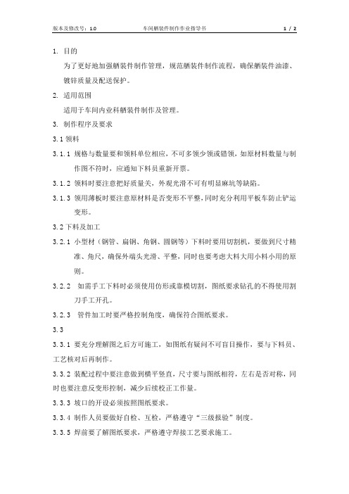
1.目的为了更好地加强舾装件制作管理,规范舾装件制作流程,确保舾装件油漆、镀锌质量及配送保护。
2.适用范围适用于车间内业科舾装件制作及管理。
3.制作程序及要求3.1领料3.1.1规格与数量要和领料单位相应,不可多领少领或错领,如原材料数量与制作图不符时,应通知下料员重新开票。
3.1.2领料时要注意把好质量关,外观光滑不可有明显麻坑等缺陷。
3.1.3领用薄板时要注意原材料是否变形不平整,同时充分利用平板车防止铲运变形。
3.2下料及加工3.2.1小型材(钢管、扁钢、角钢、圆钢等)下料时要用切割机,要做到尺寸精准、角尺,确保外端头光滑、平整,同时也要考虑大料大用小料小用的原则。
3.2.2如需手工下料时必须使用仿形或靠模切割,图纸要求钻孔的不得使用割刀手工开孔。
3.2.3管件加工时要严格控制角度,确保符合图纸要求。
3.33.3.1 要充分理解图之后方可施工,如图纸有疑问不可盲目操作,要与下料员、工艺核对后再制作。
3.3.2 装配过程中要注意做到横平竖直,尺寸要与图纸相符,左右是否对称,同时也要注意反变形控制,减少后续校正工作量。
3.3.3 坡口的开设必须按照图纸要求。
3.3.4 制作人员要做好自检、互检,严格遵守“三级报验”制度。
3.3.5 焊前要了解图纸要求,严格遵守焊接工艺要求施工。
3.3.6 焊后校正在可用加工设备条件下,尽量不用火工校正。
如遇特殊工件不能独立操作的,不要盲目施工,应与加工班探讨后再操作,避免人工、材料浪费及工期滞后。
3.3.7 所有成品舾装件必须有图号标牌,栏杆的堆放要防止挤压变形,按大小顺序堆放整齐。
3.4 油漆、镀锌3.4.1 镀锌件的表面不能有油脂油漆和清漆,此类油漆无法酸洗,如有此类油漆必须冲砂后方可镀锌。
3.4.2 每件材料镀锌是悬挂高低倾斜入池,管类(含方管)材料需在每根管件下方入锌,上方出气,达到管件内锌能全部覆盖,不能存有空气防止爆裂,入锌孔在每根管件下方距离焊缝5mm处开设,出气孔在每根管件上方距焊缝5mm处开设,如管件有圆角的需在圆角中部下方开设防爆孔。
系统设计说明书(SSDD)
网上书店系统/子系统设计(结构设计)说明(SSDD)组员:说明:1•《系统/子系统设计(结构设计)说明》(SSDD)描述了系统或子系统的系统级或子系统级设计与体系结构设计。
SSDD可能还要用《接口设计说明》(IDD)和《数据库(顶层)设计说明》(DBDD)加以补充。
2.SSDD连同相关的IDD和DBDD是构成进一步系统实现的基础。
贯穿本文的术语“系统”如果适用的话,也可解释为“子系统”。
所形成的文档应冠名为“系统设计说明”或“子系统设计说明”。
目录系统/子系统设计(结构设计)说明(SSDD) (1)1引言 (3)1.1标识 (3)1.2系统概述 (3)1.3文档概述 (3)1.4基线 (3)2引用文件 (3)3系统级设计决策 (4)4系统体系结构设计 (4)4.1系统总体设计 (4)4.1.1 概述 (4)4.1.2设计思想 (4)4.1.3 基本处理流程 (5)4.1.4系统体系结构 (6)4.1.5功能需求与系统配置项的关系 (9)4.1.6人工处理过程 (9)4.2系统部件 (7)4.3执行概念 (9)4.4接口设计 (10)4.4.1接口标识和图表...................... 错误!未定义书签。
5运行设计 (7)5.1系统初始化 (7)5.2运行控制 (8)5.3运行结束 (8)6系统出错处理设计 (12)6.1出错信息 (12)6.2补救措施 (12)7系统维护设计 (13)7.1检测点的设计 (13)7.2检测专用模块的设计 (9)8尚待解决的问题 (9)9需求的可追踪性 (9)10注解 (9)附录 (9)1引言1.1标识适用系统:所有可以连接因特网的系统标题:网上书店版本号:1.01.2系统概述本系统应该具有对图书信息的管理以及对用户信息的管理以及存储功能,并能够保存用户账号信息、购买信息等。
读者可以进行网上浏览书籍、图书检索、网上购书以及网上付款。
本项目的使用者是需要购买书籍的任意用户,故对性能要求较高,需要功能全面、方便且易于操作。
船舶铁舾件制作流程
船舶铁舾件制作流程下载温馨提示:该文档是我店铺精心编制而成,希望大家下载以后,能够帮助大家解决实际的问题。
文档下载后可定制随意修改,请根据实际需要进行相应的调整和使用,谢谢!并且,本店铺为大家提供各种各样类型的实用资料,如教育随笔、日记赏析、句子摘抄、古诗大全、经典美文、话题作文、工作总结、词语解析、文案摘录、其他资料等等,如想了解不同资料格式和写法,敬请关注!Download tips: This document is carefully compiled by theeditor. I hope that after you download them,they can help yousolve practical problems. The document can be customized andmodified after downloading,please adjust and use it according toactual needs, thank you!In addition, our shop provides you with various types ofpractical materials,such as educational essays, diaryappreciation,sentence excerpts,ancient poems,classic articles,topic composition,work summary,word parsing,copy excerpts,other materials and so on,want to know different data formats andwriting methods,please pay attention!船舶铁舾件制作流程一般包括以下步骤:1. 设计图纸解读仔细研究船舶的设计图纸,了解铁舾件的规格、形状、尺寸和安装位置等要求。
不锈钢桶搬运车SSDH操作说明书和零件手册
HANDLER, READ THESE INSTRUCTIONS BEFORE USING.DescriptionThe Wesco Stainless Steel Drum Handler units are 304 stainless steel construction including Frame, Drum Grab, Hydraulic Pump, Foot Pedal, Wheel Locks and Lifting Cable. (Items Listed Below Shown in Figures 1 or 3) - Wheels: Phenolic wheel with stainless frame and bearings [Figure 1, Item 5]. - Casters: Phenolic wheel with stainless rig and bearing [Figure 1, Item 3]. - Stainless Steel Hydraulic Pump: Copper pumping cylinder seal [Figure 3, Item D1.1], Copper sealing ring [Figure 3, Item C3.1]. - Stainless Steel Wire Rope Assembly: with zinc plated copper compression sleeve [Figure 1, Item 11 and Figure 3, Item L1.1].- Stainless Steel Wire Rope Sheave: with bearing bronze bushing [Figure 3, Item K1.1]. - Cable Guard: ABS plastic [Figure 1, Item 12]. - Carriage Rollers: UHMW Polyethylene [Figure 1, Item 7]. - Hand Grips: PVC [Figure 1, Item 17]. See nameplate on unit for capacity, load center, model number and truck serial number. This product is manufactured by:Wesco Industrial Products, Inc1250 Welsh RoadNorth Wales, PA 19454 Tel: 215-699-7031 Fax: 215-699-3836 Contact the factory for parts information and ordering.Visit us on the web at UnpackingWhen unpacking the Wesco Product, check carefully for shippingdamage and missing parts. If damage has occurred or any partsare missing, file a claim with the delivering carrier within 24 hours and notify the dealer from whom the unit was purchased.Warranty RepairsIf the unit does not work properly, contact your dealer or thefactory (215-699-7031) for units less than 1 year old.Non-Warranty Service If units are older than 1 year, repairs can be made easily on sitewith factory supplied parts.NOTE: Do not send units to the factory for service without firstobtaining a “Return Merchandise Authorization” (RMA) number from the customer service department. We will not be responsible for merchandise returned without an RMA number.General Safety Information The Wesco Model SSDH is designed for specific functions. To insure proper use, the following instructions must be adhered to: (1) Load Rating: 800 lbs (2) DO NOT use unit for loads exceeding the rated capacity. (3) This product is designed for use on level floors only. DO NOT use unit, or engage floor lock, on any incline greater than five (5) degrees.(4) Keep hands and feet clear of drum grab, carriage and wheels. (5) The drum grab must be in full contact with drum rim prior to lifting. Using the manual lock is recommended, but not necessary for operation.(6) Be certain rim of fiber or plastic drum is able to withstand the stress of drum lifting procedure.(7) Be certain that both ends of lift cable are securely fastened to jack and cable anchor before lifting load. (8) DO NOT transport load at maximum height. Transport drum 2 to 3 inches off floor. (9) Use extreme care when travelling over uneven floors. (10) DO NOT use on ramps (11) DO NOT modify this product in any way. (12) Periodically inspect for damage, and loose or missing hardware. If required remove unit from service.Operation Instructions(1) Move unit towards drum until the bottom of the drum grab firmly contacts the sidewall of the drum underneath the rim.Note: Three sets of holes in the top of the carriage allow for the adjustment of the drum grab for drums of differentheights. Raise the carriage above the frame upright until the lowest adjustment hole clears the mast. While holding theclamping head and slides with one hand, insert the adjustment pin through the appropriate set of holes to obtain the proper height for grabbing a drum(2) Engage the floor lock and raise drum grab until grab automatically clamps on the drum rim. If desired tighten thedrum grab manual lock by turning the knob clockwise. Oncesecure raise the drum 2” to 3” off of the floor by stepping on the pumping.(3) Disengage the floor lock and transport drum to the desiredlocation.(4) Engage floor lock and lower drum to floor by pressing reliefpedal located on left side of hydraulic jack. If the manual lock was engaged, release the drum grab clamp by turning theknob counter-clockwise.Note: If drum is to be positioned on or moved from a raised platform, use care during movement of drum in raised position and keep drum at transportation height whenever possible. LIMITED WARRANTY WESCO INDUSTRIAL PRODUCTS (WESCO) warrants to the purchaser of this product for a period of one year from the date of purchase that this product shall be free ofdefects in material and/or workmanship, as follows: 1. WESCO will supply, at no charge, new or rebuilt replacements for any part that fails through a defect in material and/or workmanship during the warranty period. To obtain warrantyservice, you must deliver the product prepaid, to the WESCO factory.2. This warranty does not cover any product or product part which has been subject to accident, misuse, abuse or negligence. WESCO shall only be liable under this warranty if theproduct is used the manner intended by the manufacturer as specified in the written instructions furnished with this product.REPAIR OR REPLACEMENT AS PROVIDED UNDER THIS WARRANTY IS THE EXCLUSIVE REMEDY OF THE PURCHASER. ANY EXPRESS WARRANTY NOT PROVIDED IN THIS WARRANTY DOCUMENT, AND ANY REMEDY FOR BREACH OF CONTRACT THAT, BUT FOR THIS PROVISION, MIGHT ARISE BY IMPLICATION OR OPERATION OF LAW,IS HEREBY EXCLUDED AND DISCLAIMED. UNDER NO CIRCUMSTANCES SHALL WESCO BE LIABLE TO PURCHASER OR ANY OTHER PERSON FOR ANY INCIDENTAL ORCONSEQUENTIAL DAMAGES, WHETHER ARISING OUT OF BREACH OF WARRANTY, EXPRESS OR IMPLIED, A BREACH OF CONTRACT OR OTHERWISE. EXCEPT TO THE EXTENT PROHIBITED BY APPLICABLE LAW, ANY IMPLIED WARRANTY OF MERCHANTABILITY AND FITNESS FOR ANY PARTICULAR PURPOSE ARE EXPRESSLY LIMITED IN DURATION TO THE DURATION OF THIS LIMITED WARRANTY.Some states do not allow the exclusion or limitation of incidental or consequential damages, or allow limitations on how long any implied warranty lasts, so the above limitations may notHANDLER, READ THESE INSTRUCTIONS BEFORE USING.Replacement Parts (1-9) ItemFigure 1Part No. Description Qty 1056400 Jack: Stainless Assembly (40") 1 2 056472 Weldment: Jack/Carriage 1 3 109452 Caster: Swivel, 5x2, SS 2 4 109453 Floor Lock: 304SS 1 5 109454 Wheel: 5x2 Phenolic 2 6056390 Drum Grab Automatic - S.S. 17 056481 Roller: Carriage (SSDH) 6 8 109491 Washer:SS,1/2"ID,1-1/4"OD 129 109492 Ring: Retaining, SS, 1/2"6Replacement Parts (10-18) Item Part No. DescriptionQty 10 109528 Screw: SS, Truss Hd (10-32 x 1/2) 4 11 056478 Assembly: Lift Cable 1 12 056479 Guard:"Wesco" SSDH 1 13 109527 Nut: SS, Hex Nylock, #10-32 4 14 109499 Magnet: Stainless Encased 2 15 108944 Ring: Circle, Cotter Pin 1 16 056480 Pin: Adjustment (SSDH) 1 17 108226 Handgrip: 1" Black PVC 2 18 056539 Sheave: SS, 1/4" Wire Rope 1NOTE: (CARRIAGE ASSEMBLY)HANDLER, READ THESE INSTRUCTIONS BEFORE USING.Figure 2¼” 20 x 3/8” Set Screw (Use Pipe Plug (Use 5/32” Hex Wrench) Assembly RetainerBreather Hole Hydraulic Jack Operation Jack Start Up :To be certain your unit is in working order, place an approximately 200 lb. load on the platform and pump the load to full height at least 5 or 6 times. If jack does not pump or pumps only slightly at the outset, pump the pedal vigorously at least 12 times to dislodge any air pockets that might have located in the unit during shipment. If this procedure does not correct the problem; loosen assembly retainer (see Figure 2) and pump the pedal once or twice. This will cause the oil to flow, breaking any air lock that might exist. Re-tighten the assembly retainer before using the unit. If the unit does not reach proper height, the oil reservoir is low and additional hydraulic fluid should be added. This can be done by removing both fill screws (See Figure 2) and washers and filling to level of the lower hole. Use premium grade ISO #32 Anti-Wear Hydraulic Pump oil. The oil must be perfectly clean, we recommend straining the oil prior to use. After filling it may be necessary to rebleed the unit as described above. If any oil leaks exist after completion of above procedure, contact your dealer immediately. WARNING: Do not attempt repairs on any new unit should failure occur. Doing so will void the warranty.Speed Adjustment READ THIS PROCEDURE COMPLETELY PRIOR TO ATTEMPTING ADJUSTMENT! In some instances, the lowering speed of the platform may require adjustment. This can bedone as follows(1) Using the adjustment screw that is part of the Pumping & Release Valve Rebuild Kit (Key C3). See Figure 3 for a detail of this part.(2) Remove pipe plug. Insert 1/8” Hex Wrenchand adjust by holding relief pedal down with left hand while turning hex wrench clockwise until you feel the relief pedal raising up. (Should be about ¾” of travel). Testing Speed (1) Pump up jack until platform is approximately about 1.5 feet from bottom. (2) Mark side of truck frame with a pencil at top of platform. Place a second mark exactly one foot down. (3) Time platform drop speed between two marks (without a load). It should be about 18seconds.If time is less than 18 seconds, turn set screw in ¼ turn clockwise increments until slower speed is reached. Turn counterclockwise if time is greater than 18 seconds, if a faster speed is desired. It is recommended to use unit at slowest acceptable speed . Unit should be further tested under full load, to insure thatlowering speed is not too fast.HANDLER, READ THESE INSTRUCTIONS BEFORE USING.Hydraulic Jack Parts ListItem Part Description Part NumberA Pumping Pedal Assembly (Stainless Steel) 056442B Relief Pedal Assembly (Stainless Steel) 056443C Pumping & Release Valve Rebuild Kit (Stainless Steel with copper seal rings)Note: Includes items C1, C2 & C3056444C3.1 Sealing Ring (Copper) Included in 056444D Jack Body (Stainless Steel) 056445D1.1 Pumping Cylinder Seal (Copper) Included in 056445E Jack Base (Stainless Steel) 056446F Main Piston Hardware (Internal Seals) 0510767G Main Piston (Stainless Steel) 056424H Inner Cylinder (Internal) 051038I Outer Cylinder (Stainless Steel) 056422J Outer Cylinder Hardware (Stainless Steel with Buna seals) 056447K Roller Carrier Assembly (Stainless Steel with Bronze Bushing) 056448 K1.1 Bushing (Bearing Bronze) Included in 056448 L Lift Cable Assembly (Stainless Steel with Zinc Plated Copper Compression Sleeve) 056478 L1.1 Compression Sleeve (Zinc Plated Copper) Included in 056478 M Magnet/ Latch Assembly (Stainless Steel) 056449* Seal Kit (contains all starred items) 052722Complete Jack (without cable) 056400Key Numbers reference the Hydraulic Jack Parts Drawing (Figure 3) on page 5.HANDLER, READ THESE INSTRUCTIONS BEFORE USING. Hydraulic Jack Parts DrawingFigure 3。
舾装系统托盘更改讲解
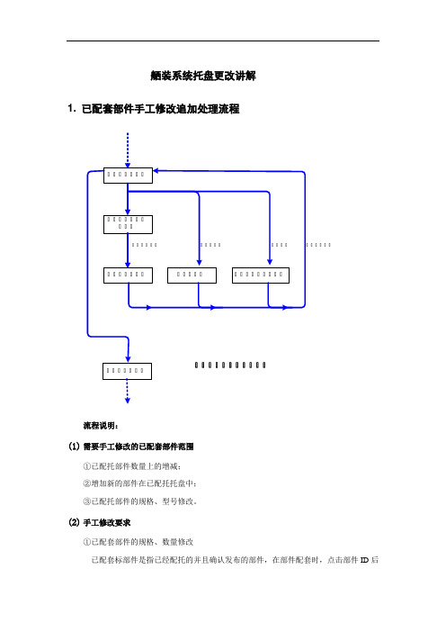
舾装系统托盘更改讲解1. 已配套部件手工修改追加处理流程流程说明:(1)需要手工修改的已配套部件范围①已配托部件数量上的增减;②增加新的部件在已配托托盘中;③已配托部件的规格、型号修改。
(2)手工修改要求①已配套部件的规格、数量修改已配套标部件是指已经配托的并且确认发布的部件,在部件配套时,点击部件ID后面的按钮就会在清楚显示部件的所有信息。
这类部件的修改:可先输出打印《托盘配套文件》,检查系统配套的部件是否正确;也可不印,直接修改操作。
②增加新配件将新的部件配到已经发布的托盘中去,也要通过设计变更。
③标准部件的数量修改要求:只能设计变更窗口界面中的“数量”一栏。
第1章设计变更设计变更设计管理系统生成更改单号的步骤(针对需要更改托盘清单)1. 在进行托盘清单设计变更之前,首先要在设计管理系统里的设计质量模块进行质量项目编制,如下图:2. 然后确定编制好的质量项目是否需要下指示单,如不需要下指示单,只需要修改蓝图,就在质量项目派工单中编写‘出更改单派工单’,见下图中的3:3. 在个人质量任务中进行出更改单处理,由于需要修改托盘,因此需要选择SPEM出图,点确定按钮,生产更改单号,这个更改单号和舾装系统关联,这样在舾装系统就可以出更改通知单,见下图:4. 如该质量项目不但需要修改图纸,而且也需要下指示单处理该问题,就需要先生成出指示单派工单,见下图中的2:5. 按照出指示单的方法先出指示单,但需要在修改图纸的复选框里打‘√’,见下图:6. 在个人质量项目中会生成一个派工单类型为‘指示单项目’,在这个项目之下就可以出更改单,后面的步骤和上述直接出更改单派工单的步骤一样,见下图:舾装系统出更改单的步骤:(1)功能通过更改单修改已经发布到物资系统的清单以及托盘的数据。
(2)打开点击“设计变更——设计变更”,进入窗口如下图所示:(3)工具条(4)操作①查询在下面的各文本框输入查询条件,按回车。
若要清除条件,点击按钮。
- 1、下载文档前请自行甄别文档内容的完整性,平台不提供额外的编辑、内容补充、找答案等附加服务。
- 2、"仅部分预览"的文档,不可在线预览部分如存在完整性等问题,可反馈申请退款(可完整预览的文档不适用该条件!)。
- 3、如文档侵犯您的权益,请联系客服反馈,我们会尽快为您处理(人工客服工作时间:9:00-18:30)。
SSD铁舾件设计系统操作使用说明书
上海东欣软件工程有限公司
二ΟΟ六年八月
目录
1标准部件输入 (2)
2铁舾件处理 (3)
2.1安装铁舾件操作 (3)
2.2制作钢板并安装操作 (4)
2.3修改铁舾件操作 (4)
2.3.1重命名铁舾件操作 (4)
2.3.2移动铁舾件操作 (5)
2.3.3复制铁舾件操作 (5)
2.3.4旋转铁舾件操作 (5)
2.3.5伸缩型材操作 (5)
2.3.6翻转型材操作 (5)
2.3.7替换型材操作 (5)
2.3.8修改参数操作 (5)
2.3.9修改材质操作 (6)
2.4删除铁舾件操作 (6)
2.5标准模型库存取操作 (6)
2.6材料清单生成操作 (6)
3零件和托盘处理 (7)
3.1铁舾件托盘建立 (7)
3.2铁舾件零件处理 (7)
3.3铁舾件托盘处理 (7)
4图纸处理 (8)
4.1铁舾件制作图生成 (8)
4.2图号管理、图纸输出和图面处理 (8)
5生产用表处理 (9)
5.1铁舾件制作图生成 (9)
5.2查看输出文件夹 (9)
1 标准部件输入
在启动界面上点击参数化标准部件按扭,则可以将参数化部件库(data/hdssd.pam)中的参数化铁舾件的参数标准化,以部件代号作为选择的标示保存在标准数据库(data/vspd_std)和实体部件库(data/myspd.pel)中,以备交互布置时使用。
标准部件输入对话框如下:
在标准部件输入对话框中先选择大类,确定大类后,再选择小类,然后再选择参数类型。
选择相关的工程目录,则保存到工程部件库(工程编号.PEL)中,如果要保存到系统部件库(myspd.PEL)中,则选择EFCSD目录即可。
在下面的表格中输入部件代号以及与该代号相关联的参数值,点击保存按扭即可。
参数名称的意义可查看PPD.exe。
如需要输入多行标准部件,点击添加按钮,系统自动增加部件输入的空白项,供用户进行部件的输入。
如果要删除部件,只要删除该部件代号,然后再按保存按钮即可。
如果要修改表格中内容,直接在表格中修改,修改好后点击保存按钮即可。
按退出按钮,系统自动退出对话框,如果部件不保存,则自动放弃部件的输入。
2 铁舾件处理
首先结束其它交互操作(按ESC键),然后从主工具条中按铁舾件布置按钮,则显示铁舾件布置工具条
来选择铁舾件。
选择好铁舾件类别后,则在图形平面上通过点输入操作确定安装基点。
基点选择好后,如果点击鼠标右键确定,则表示该部件所有参数均不计算。
如果输入第二个点用来确定铁舾件的安装方向和部分外形尺寸。
比如如果是基本型材,则第第二个点确定它的拉伸方向和型材长度;但如果是扶梯或栏杆,则是扶梯的延伸方向和高度;盖子则是放置方向和厚度等等。
2.2 制作钢板并安装操作
在进入制作钢板并安装操作前,可用AutoCad的画图功能画出板的形状,有内孔的也要一并画出,但是注意一定要闭合,然后开窗或点击选择所画图形的所有线条,注意不要将其余线条选择上,否则之后
转化为本系统闭合的样条数据时会出现如右对话
框。
提示输入的图形有错误。
图形画好后进入制
作钢板并安装操作,从铁舾件布置工具条中点击
制作钢板并安装按钮
,则显示修改铁舾件工具条
,该工具条中有九个按钮,依次是:重命名铁舾件、移动铁舾件、复制铁舾件、旋转铁舾件、伸缩型材、翻转型材、替换型材、修改参数和修改材质。
前四个功能可单独、整体或选择修改所有类别铁舾件,而伸缩型材、翻转型材和替换型材三个功能则是针对型材做的修改,修改参数和修改材质功能则可修改任意铁舾件的参数值和材质。
下面分别详细介绍:
2.3.1 重命名铁舾件操作
由于铁舾件是根据零件名称来区分是否属于一体,那么零件名称的正确与否就相当重要,点击重命名铁舾件按扭可以修改铁舾件的零件
名称。
可以输入或选择已有的零件名称做为新的零件名称。
这里提供了三种模式:单独、整体和选择。
单独模式则是把选中的铁舾件单独改名,
整体模式则是把和选中的铁舾件零件名
称一样铁舾件全部改名,选择模式则是把
选中的铁舾件统统改名。
在重命名操作中
如果选择的是钢板,可以通过输入新的厚
度修改板的厚度,如果厚度为0则不修改,保留原来的板厚。
2.3.2 移动铁舾件操作
移动铁舾件操作和重命名一样,可选择单独、整体和选择三种模式移动。
但是移动不可改变零件名称和板厚。
确定移动模式后,在图形平面上选择要移动的铁舾件,然后输入移动起点和移动终点即可。
2.3.3 复制铁舾件操作
复制铁舾件一样可以选择单独、整体和选择三种模式,并且可以修改新复制出的铁舾件的零件名称和板厚。
对话框同重命名对话框。
操作同移动操作。
2.3.4 旋转铁舾件操作
旋转铁舾件一样可以选择单独、整体和选择三种模式。
对话框同移动对话框,不可修改零件名称和板厚。
确定旋转模式后,在图形平面上选择要旋转的铁舾件,然后输入旋转基点和旋转轴方向,然后输入旋转角度或旋转最终方向即可。
2.3.5 伸缩型材操作
型材的长度是可以通过伸缩型材操作来
修改的,选择要修改的型材,则出现如左的对
话框。
提示是否按照板架或其它铁舾件来切割
型材,自动计算型材的切割角度。
如果选择是,
则系统将提示选择相关板架和铁舾件;如果选
择否,则可以通过输入点来拉伸和缩短型材。
2.3.6 翻转型材操作
型材中有部分型材具有非对称性,比如角钢等,需要将折边反向。
进入翻转操作后,点击要翻转的型材即可。
2.3.7 替换型材操作
使用该功能可将已安装的型材类型替换,比如角钢替换为扁钢。
点击该按扭,选择要替换的型材,系统弹出如安装铁舾件一样的部件选择对话框,选择新的型材类型,点击确定按扭即可。
2.3.8 修改参数操作
由于本系统的部件都采用了参数化设计部件,所以可以通过修改它的参数来
修改铁舾件的外形尺寸。
修改参数对话框如下图所示。
2.3.9 修改材质操作
已安装的铁舾件可通过点击该按扭修改材质。
信息栏中
会提示选择要修改材质的铁舾件,在主控界面的对话框中选
择修改后的材质,在图形中点击要修改的铁舾件即可。
2.4 删除铁舾件操作
从铁舾件布置工具条中按删除铁舾件按钮
,主控界
面中出现标准模型库存取对话框。
用户可以通过这一操作将拼
装好的铁舾件保存起来,可再次利用。
如果要保存铁舾件,则
首先输入标准模型名,如果和已有模型名重复,系统会提示是
否覆盖旧的数据,点击保存按扭,在图形平面上选择要保存的
铁舾件,系统会将和选择的铁舾件同一零件名的所有铁舾件作为一体保存起来。
如果点击删除按扭,则会把标准模型名下拉框中显示的标准模型删除。
如果想要调用,则直接在图形平面上选择安装位置即可。
取出的铁舾件的零件名称还是保存时的名称。
之后可通过重命名操作来修改它们的零件名。
2.6 材料清单生成操作
从铁舾件布置工具条中按材料清单生成按钮
3 零件和托盘处理
首先结束其它交互操作(按ESC键),然后从主工具条中按生产信息按钮,
则显示生产信息工具条
,则在
主控界面中显示铁舾件托盘处理对话框,在这里可以选择生
成托盘零件、删除托盘零件、删除整个托盘和编辑托盘零件。
详细说明见《管系操作说明书》。
4 图纸处理
首先结束其它交互操作(按ESC键),然后从主工具条中按图纸输出按钮,则显示图纸输出工具条
5 生产用表处理
首先结束其它交互操作(按ESC键),然后从主工具条中按生产用表按钮
,该工具条中有两个按钮,依次是托盘管理表生成和查看输出文件夹。
5.1 铁舾件制作图生成
在生产用表工具条中点击托盘管理表生成按钮。