拓普康CT80说明书-中英文
olct80中文说明书

pps7
pps8
pps7
4 … 20 mA 检测仪的连接 (3 线)
输入 1
输入 2
pps8
pps1 pps2 pps4 pps3 pps1 pps2 pps4 pps3
pps7
pps8
pps7
pps8
把输入检测仪(4…20mA)的负端连接到 OLCT80 的负端(V-)
把输入检测仪(4…20mA)的负端连接到 OLCT80 的负端(V-)
2. 安装 ................................................................................................................... 12
2.1. 机械安装................................................................................................................................................ 12 2.2. 电气安装................................................................................................................................................ 12
dopodD802用户手册

3.1.3 “今日”屏幕3.1.4 状态图标3.1.5 程序3.1.6 导航条与指令条3.1.7 弹出菜单3.1.8 通知3.2 输入信息3.2.1 使用输入面板3.3 在屏幕上书写3.4 在屏幕上画图3.4.1 创建一个图形3.4.2 选择图形3.5 录音3.5.1 单独录音3.5.2 在文档中嵌入录音3.6 搜索3.7 使用常用短语第四章使用您的电话4.1 电话功能简介4.1.1 关于拨号界面4.1.2 输入PIN号4.1.3 检查网络连接4.1.4 打开/关闭飞行模式4.1.5 调整通话/铃声音量4.2 拨打电话4.2.1 从拨号界面拨打电话4.2.2 从联系人列表拨打电话 2425262828292930323333343434363637383838393939404141414.2.3 从快速拨号中拨打电话4.2.4 从通话记录中拨打电话4.2.5 拨打紧急电话4.2.6 拨打国际长途4.3 接听或拒接来电4.4 打开扬声器功能4.5 电话随笔4.5.1 创建电话随笔4.5.2 查看电话随笔4.6 语音信箱4.7 导入/导出联系人4.7.1 从通话记录中创建联系人4.8 使用PIN码保护您的电话第五章同步信息5.1 同步数据5.1.1 同步电子邮件的收件箱5.1.2 同步日历5.1.3 同步联系人5.1.4 同步任务5.1.5 同步步骤5.2 传输文件第六章定制多普达D8026.1 调整设置参数6.2 标签6.3 主人信息6.4 今日6.5 声音和提醒4246474848494949505051515152535353545454585858596161626364656868696970717475777777787979798081828282838383846.6 密码 6.7 按键 6.8 电话 6.9 菜单 6.10 输入 6.11 关于 6.12 内存 6.13 删除程序 6.14 时钟和闹钟 6.15 电源 6.16 背景灯第七章 个人信息管理功能 7.1 日历7.1.1 显示约会列表 7.1.2 创建一次约会 7.1.3 使用摘要 7.2 联系人7.2.1 显示联系人列表 7.2.2 创建联系人 7.2.3 查找联系人 7.3 任务7.3.1 显示任务列表 7.3.2 创建一个任务 7.4 便笺7.4.1 显示便笺列表 7.4.2 创建一个便笺 第八章 网络应用848485868891929296979899991091051081081101101101121131131161161161178.1 连接8.2 Internet 设置 8.3 WAP 设置8.4 Internet Explorer Mobile 8.5 Pocket MSN 8.6 蓝牙8.6.1 蓝牙模式 8.6.2 绑定 8.6.3 蓝牙FTP8.6.4 通过蓝牙无线发送数据 8.6.5 通过蓝牙无线接收数据 第九章 信息功能 9.1 信息概述 9.2 短信 9.3 彩信9.3.1 创建与编辑彩信 9.3.2 发送和接收彩信 9.3.3 转发彩信第十章 商务程序 10.1 Word Mobile 10.2 Excel Mobile10.3 PowerPoint Mobile 10.4 Adobe Reader LE 10.5 图片和视频 10.5.1 传送图片10.5.2 查看图片和视频 10.5.3图片排序1.点击如果您希望输入的汉字没有声母,请点击软键盘上的2.摄像:点击3.浏览图像:在拍摄界面用触笔选择 ,即可进入图像浏览。
80mm Kitchen Cloud Printer 快速开始指南说明书

4 Paper Feed Button Long press the paper feed button to start blank paper feed, and release to stop paper feed.
cause radio interference. In this case, the user may be required to take practical measures against interference.
Important Safety Instructions · Avoid installation or use during lightning, otherwise there is a risk of
: indicates that the content of the toxic and hazardous substance in at least one homogeneous material of the component exceeds the limit stipulated in SJ/T 11363-2006. However, as for the reason, because there is no mature and replaceable technology in the industry at present.
close to fire sources or ignited; · Try to use it in a clean and dust-free environment to prevent small items
拓普康操作
使用手册T OPCON GPS 配套软件目录第一章前言 (3)1.1 系统要求 (3)1.2 安装和卸载 (3)第二章准备工作 (3)2.1 GPS 系统(GPS+) (3)第三章新建一个作业 (4)3.1 新建一个GPS+的设置 (6)第四章存储数据 (13)4.1 增加和编辑点 (13)4.2 增加和编辑编码 (15)第五章导入和导出 (18)5.1 导入 (18)5.1.1 由作业导入 (18)5.1.2 由文件导入 (19)5.1.3 由手簿导入 (21)5.2 导出 (21)5.2.1 由作业导出 (21)5.2.2 由文件导出 (23)5.2.3 由手簿导出 (24)第六章测量 (26)6.1 坐标转换 (26)6.2 设置基准站 (27)6.3 点测量 (27)6.4 线测量 (28)第七章放样 (30)7.1 点放样 (30)7.2 线放样 (31)TopSURV 操作手册.doc 1第八章CoGo (32)8.1 坐标反算 (32)8.2 交点 (32)8.3 尺度比 (33)8.4 平移 (33)8.5 旋转 (34)附:注意事项35TopSURV 2 操作手册.doc第一章前言本手册简要说明了TopSURV(GPS)软件的操作,以便于用户尽快入门。
有关TopSURV(GPS)软件的详细说明,请参阅《拓普康TopSURV (GPS) 软件参考手册》。
有关TopSURV 软件在全站仪方面的使用,本手册未做任何的说明,请参阅相关的其他资料。
1.1 系统要求显示器分辨率为240x320 或320x240、RAM 32MB、Windows CE 3.0 版或更高版的手簿(控制器)。
1.2 安装和卸载安装TopSURV,PC机上需要有Windows操作系统、Microsoft Active Sync 软件,并将PC机和手簿相连。
根据安装程序的提示即可自动完成TopSURV的安装。
卸载TopSURV,需要利用手簿上Windows CE控制面板的“卸载程序”功能。
CT系列产品使用说明书
Table of contents目录表重要安全事项和符号说明.................................................................1前言......................................................................................................2前板功能介绍.....................................................................................3后板功能介绍.....................................................................................4技术指标.............................................................................................5故障排除.............................................................................................6Important Safety Instruction and symbol description......8Foreword...........................................................................................9Front panel functions..................................................................10Rear panel functions....................................................................11Specifications.................................................................................12Troubleshooting. (13)User Manual 's 用户使用手册CT Series重要安全事项和符号说明重要安全事项1. 阅读这些规定,注意所有警告,遵守这些规定。
托普康电子经纬仪(DT-200 200L系列)使用说明书
2)使用仪器时,请穿上必要的安全装(如安全鞋、安全帽等)。
免责声明
1)本产品的用户应完全按使用说明书进行使用,并对仪器的性能进行定期 检查。 2)因破坏性、有意的不当使用而引起的任何直接或间接的后果及利益损失, 厂方及
代表处对此不承担责任。 3)因自然灾害(如地震、风暴、洪水等)、火灾、事故或第三者责任而引 起的任何直
10各部件名称及功能11部件名称1112dt202l205l207l209l131412显示显示内容显示内容竖直角tilt倾斜正模式只对dt205205lhr右水平角功能键选择模式hl左水平角百分比坡度ht角度重复测量角度显示单位gon百分度8avg重复测量次数角度重复测量的平均值13操作键功能模式功能开关键rep重复角度测量水平右角左角测量照明显示开关竖角显示竖角百分比显示选择向左移动光标hold水平角保留向右移动光标0set水平角置零光标闪烁数字递增func第二功能键选择15调整模式和选择模式模式调整为竖直角为0模式打开仪器同时按0set键
担责任。
7
目录
前 言......................................................................................................................1 常规注意事项................................................................................................................2 安全使用标志................................................................................................................4 安全使用注意事项........................................................................................................4 激光安全........................................................................................................................6 用户................................................................................................................................7 免责声明........................................................................................................................7 目 录..........................................................................................................................8 标准配置......................................................................................................................10 1 各部件名称及功能..................................................................................................11 1.1 部件名称................................................................................................................11 1.2 显示........................................................................................................................15 1.3 操作键........................................................................................................................
MAGNET Field中文说明书_20120801_最终版

CTEK UC 800电池充电器用户手册说明书

d) If battery acid contacts skin or clothing, wash immediately with soap and water. ,IDFLGHQWHUVH\HLPPHGLDWHO\ÀRRGH\HZLWKUXQQLQJFROGZDWHUIRUDWOHDVW minutes and get medical attention immediately.
b) Be sure area around battery is well ventilated while battery is being charged. c) Clean battery terminals. Be careful to keep corrosion from coming in contact
US • 3
13. PREPARING TO CHARGE
a) If necessary to remove battery from vehicle to charge, always remove grounded WHUPLQDOIURPEDWWHU\¿UVW0DNHVXUHDOODFFHVVRULHVLQWKHYHKLFOHDUHRIIVRDV not to cause an arc.
with eyes. d) $GGGLVWLOOHGZDWHULQHDFKFHOOXQWLOEDWWHU\DFLGUHDFKHVOHYHOVSHFL¿HGE\EDW-
WHU\PDQXIDFWXUHU'RQRWRYHU¿OO)RUDEDWWHU\ZLWKRXWUHPRYDEOHFHOOFDSVVXFK as valve regulated lead acid batteries, carefully follow manufacturer’s recharging instruction. e) 6WXG\DOOEDWWHU\PDQXIDFWXUHU¶VVSHFL¿FSUHFDXWLRQVZKLOHFKDUJLQJDQGUHFRPmended rates of charge. f) Determine voltage of battery by referring to car owner’s manual and make sure that WKHRXWSXWYROWDJHVHOHFWRUVZLWFKLVVHWDWFRUUHFWYROWDJH,IFKDUJHUKDVDGMXVWDEOH charge rate, charge battery initially at lowest rate.
GTS-720N拓普康操作中文说明书

前言
常规注意事项 安全使用标志 安全使用注意事项 用户 免责声明 目录 标准配置
1 仪器各部件名称及其功能…………………………….………….1
1.1 部件名称……………………………………………………………………………1
1.2 显示屏………………………………………………………………………………3
1.6 电池盖传感器 …………………………………………………………………8
1.7 触摸屏校准 ………………………………………………………………………9
1.8 显示屏操作键………………………………………………………………………10
1.9 关机
………………………………………………………………………11
1.10 功能键(软键)……………………………………………………………………11
2.5.1 用软键设置倾斜改正………………………………………………………22 2.6 仪器系统误差的补偿………………………………………………………………23 2.7 输入数字和字母的方法……………………………………………………………24 2.8 CF 数据存储卡 ……………………………………………………………………26 2.9 数据通讯…………………… ……………………………………………………27
1.3 背景光调节
为了节约电量,GTS-720 系列将会自动判断是否关背景光或调节其亮度。您可以根据 自己的需求来设置。
1.3.1 如何调节背景光亮的时间
1. 在 WinCE 桌面,按“开始/设置/控制面板/电源”,
4
2. 按“背景光”,
3. 设置背景光亮的时间,
可根据需要设置背景光亮的时间。出厂设置为 3 分钟。 按[OK]保存。
拓普康Topcon_DL103电子水准仪使用手册

5
目
录
前言…………………………………………………………………………..1 例外责任声明………………………………………………………………..2 注意事项……………………………………………………………………..3 安全使用标志………………………………………………………………..4 安全使用注意事项…………………………………………………………..4 用户…………………………………………………………………………..5 标准配置……………………………………………………………………..5 目录…………………………………………………………………………..6 各部件名称和功能………………………………………………………….7
12
照准与调焦
(1) 将望远镜对准标尺,观察望远镜,使三角标志的顶点对准标尺。 (2) 其次,任意方向旋转调焦螺旋直到看清标尺。 (3) 最后,用水平微动螺旋精确照准标尺。
注:
一旦水准仪已经调焦且瞄准标尺,即可一边左、右移动眼睛一边通过望远镜观察, 按理此时十字丝和标尺之间不会出现偏离,若有偏离,则应仔细调焦仪器或调焦 目镜,以消除误差。
5. 略微松开三脚架中心螺旋,在架头上轻轻移动仪器,使锤球正好对准给定点, 然后将三脚架中心螺旋旋紧。
11
仪器整平
通过圆水准镜,可以显示圆水准器气泡的位置。 转动离圆水准器最远的两个脚螺旋,使圆水准器气泡位于和上述两个脚螺旋中心 连线的垂线上。(如下图所示) 1. 然后旋转第三个脚螺旋,使气泡居中。
拓普康电子水准仪使用手册
DIGITAL LEVEL INSTRUCTION MANUAL
DL-103
/ QQ:2500580332
前言
EchoSpan LU80 Series Quick Start说明书

QS300310 Rev C1 ©2016 Flowline, Inc.All Rights ReservedMade in USAUltrasonic Liquid Level TransmitterLU80 Series Quick StartFlowline, Inc. | 10500 Humbolt Street, Los Alamitos, CA 90720 p 562.598.3015 f 562.431.8507 w | 2QS300310 Rev C1WE DO YOUR LEVEL BESTThank you for purchasing EchoSpan ®. The sensor provides integrated LCD and three push-button configuration . This quick start includes everything you’ll need to get the sensor up and running.COMPONENTSDepending on how the sensor part number that was shipped, EchoSpan ® comes with a Viton ® gasket for installation and the Quick Start.EchoSpan ®LU80-5101 & LU80-5161Viton®gasket (1”) P/N: 200128ENCLOSUREWhile the switch housing is liquid-resistant the EchoSpan ® is not designed to be operational when immersed. It should be mounted in such a way that the enclosure and transducer do not come into contact with the application media under normal operational conditions. The enclosure has a flip cover with dual 1/2” NPT female conduit ports and an internal terminal strip for wiring. Before closing the enclosure, make sure that the enclosure gasket is properly seated, and that any conduit fittings, cable connectors or plugs are installed correctly and sealed. Note: If using the Flowline LM90-1001 (liquid tight fitting) on the ½” conduit, the cable minimum is 0.170” (4.3mm) and the maximum is 0.450” (11.4mm).MOUNTING THE ECHOSPAN®The sensor should always be mounted perpendicular to the liquid surface using the provided Viton® mounting gasket. Make sure that there are no restrictions or obstacles in the path of the acoustic signal. For further mounting information, please refer to the EchoPod® manual and instruction video located at .EchoSpan®has 1” N PT or G threads and requires care in fitting selection and mounting to reduce any coupling of the ultrasonic signal to the mounting structure. The below fittings are recommended.Installation in existing 2” fittings:1) Use a LM52-1400 2” thread x 1” thread a dapter or a LM52-14102” slip x 1” thread adapter. Adapters with an air gap around the 1inch threads are recommended.Installation in plastic tanks (use one of the following):1) Use a 1” bulkhead fitting, such as the LM52-1890 bulkheadfitting.2) Use a larger bulkhead fitting, such as the LM52-2890 with areducer bushing such as the LM52-1400.3) Weld a plastic 1” half coupling to the tank top.Installation in metal tanks (use one of the following):1) Use the LM52-1890 bulkhead fittings.2) Use a flange with a 1” riser, such as the LM52-1850 (where thethread is above the plane of the flange). Do not use a blindflange with a tapped 1” thread.3) Use a larger flange with a 2” thread and add a reducer bushingsuch as the LM52-1400.Note: While installations directly into a 1”metal fitting are not recommended, acceptable results may be obtained if the 1” fitting is a half coupling in form and the outer diameter of the coupler is tightly wrapped with vinyl tape.Installation in open tanks and sumps:1) Use Flowline's LM50-1001-1 side mount bracket. LM52-1400 LM52-1410 LM52-2890 LM52-1850 LM50-1001QS300310 Rev C1 3 |IMPORTANT MOUNTING GUIDELINES1) Never mount the sensor at an angle.2) Liquid should never enter the dead band.3) Mount at least 2” from the side wall.4) Never mount the sensor in a vacuum.5) Do not obstruct the sensor’s beam width.Mounting with a Stand-Pipe:A stand-pipe may be used to dampen turbulence, separate surface foam from the point of measurement or increase performance in heavy vapor. When mounting the sensor in a stand-pipe, the minimum diameter of the pipe is 2”. Larger diameter pipes can be used. The pipe should be attached with a coupling or tank adapter and reducer bushing. Avoid the use of multiple pipe fittings when possible. An ideal mount would be to select a 2” coupling (S x T or S x S) and connect the pipe to the inside slip and use a reducer bushing to attach the sensor (see example below).The pipe length should run the measurement span and the bottom of the pipe should remain submerged at all times to prevent foam from entering the pipe. Cut the bottom end of the pipe at 45° and drill a 1/4”pressure equalization hole high in the dead band. The pumps should not drive liquid past the open end of the standpipe which causes the liquid in the pipe to oscillate.EchoSpan®LU802” x 1”Reducer Bushing(TxT)2” Coupling(S x T)Vent Hole (1/4”)2” PVC PipeLU80 attached to a LM52-1400 (2”x1” reducer bushing)to a SxT 2” Coupling.Stand-Pipe Mounting|4QS300310 Rev C1QS300310 Rev C1 5 |WIRING THE ECHOSPAN ®The following wiring diagram can be used for the 4-20 mA output of the EchoSpan ®.Notes on Safety∙ Where personal safety or significant property damage can occur due to a spill, the installation musthave a redundant backup safety system installed.∙ Wiring should always be completed by a licensed electrician. ∙ The sensor must be chemically compatible with the application. ∙ Design a fail-safe system for possible sensor and/or power failure. ∙ Never use the sensor in classified hazardous environments.Wiring to Common DevicesWiring to Loop DisplayWiring to Generic PLCWiring to DataView™LI55 seriesEnter the appropriate tank level set points for your application.| 6QS300310 Rev C1TOP-LEVEL MENUThe sensor is configured with the three buttons on the sensor face (UP , DOWN and SELECT ) and the sensor’s LCD. To access the sensor’s Top -level menu, simply hold down the SELECT button for five seconds. The display menu will automatically begin to scroll through the TOP-LEVEL MENU.When the menu scrolls to an item you wish to configure, simply press the SELECT button to choose that item. The TOP-LEVEL MENU will continue to scroll through the following (UNITS – TANK – SAFE – TGCAL – VALUES – HELP – RUN ). If you miss your selection, it will appear again shortly.∙ To return to the TOP-LEVEL MENU, press SELECT when EXIT appears.∙ To return to Operational Mode of the sensor, press SELECT when RUN appears in the TOP-LEVELMENU.∙ Note: To speed up the scrolling of the values on the display, hold down the SELECT button whileholding down the UP or DOWN buttons. Set UnitsThe EchoSpan ® displays information in the following units: inches, feet, centimeters, meters or percentage. The value shown on the display represents the amount of liquid in the tank.1) In TOP-LEVEL MENU mode, select UNITS .2) Next, select INCHES, FEET, CM, METERS or PERCNT .SAVED will display. 3) Finally, select EXIT to return to the TOP-LEVEL MENU.Measuring Sensor Height and Fill-Height∙ HEIGHT – Distance from the transducer face to the bottomof the tank. ∙ FILL-H – Maximum fill height of the liquid from thebottom of the tank.Note: The Height and Fill Height settings also determine the 4 to 20 mA current span. The Height setting determines the 4mA position and the Fill-H setting determines the 20 mA position.SET HEIGHT AND FILL HEIGHTThis setting customizes the reading for your installation. Follow these instructions to set the height and fill height for your tank:1) In TOP-LEVEL MENU mode, select TANK.2) Select HEIGHT.3) Use the UP and DOWN buttons, set theHEIGHT of your tank.4) To enter the value, press and hold SELECT for2 seconds and release. SAVED will display.HEIGHT is now set.5) Select FILL-H.6) Use the UP and DOWN buttons, set theHEIGHT of your tank.7) To enter the value, press and hold SELECT for 2 seconds and release. SAVED will display. FILL-H isnow set.8) Select EXIT to return to the TOP-LEVEL MENU.9) Select RUN to return to Operational Mode.Note: The Height and Fill Height settings also determine the 4 to 20 mA current span. The Height setting determines the 4mA position and the Fill-H setting determines the 20 mA position.Select Fail-Safe Output / LOST:Current Output or LOST setting can be set to output a current of4mA, 20mA, 21mA, 22mA or HOLD (last known value). During fail-safe, the display will read LOST.1) In TOP-LEVEL MENU mode, select SAFE.2) Select 4mA, 20mA, 21mA, 22mA or HOLD. SAVED willdisplay.3) Select EXIT to return to the TOP-LEVEL MENU.TROUBLESHOOTINGIf you face any issues not addressed in this Quick Start, please referto the EchoSpan®Manual located on Flowline’s website at.QS300310 Rev C1 7 |WARRANTYFlowline warrants to the original purchaser of its products that such products will be free from defects in material and workmanship under normal use and service in accordance with instructions furnished by Flowline for a period of two years from the date of manufacture of such products. Flowline's obligation under this warranty is solely and exclusively limited to the repair or replacement, at Flowline's option, of the products or components, which Flowline's examination determines to its satisfaction to be defective in material or workmanship within the warranty period. Flowline must be notified pursuant to the instructions below of any claim under this warranty within thirty (30) days of any claimed lack of conformity of the product. Any product repaired under this warranty will be warranted only for the remainder of the original warranty period. Any product provided as a replacement under this warranty will be warranted for the full two years from the date of manufacture.RETURNSProducts cannot be returned to Flowline without Flowline's prior authorization. To return a product that is thought to be defective, go to , and submit a customer return (MRA) request form and follow the instructions therein. All warranty and non-warranty product returns to Flowline must be shipped prepaid and insured. Flowline will not be responsible for any products lost or damaged in shipment.LIMITATIONSThis warranty does not apply to products which: 1) are beyond the warranty period or are products for which the original purchaser does not follow the warranty procedures outlined above; 2) have been subjected to electrical, mechanical or chemical damage due to improper, accidental or negligent use; 3) have been modified or altered; 4) anyone other than service personnel authorized by Flowline have attempted to repair; 5) have been involved in accidents or natural disasters; or 6) are damaged during return shipment to Flowline. Flowline reserves the right to unilaterally waive this warranty and dispose of any product returned to Flowline where: 1) there is evidence of a potentially hazardous material present with the product; or 2) the product has remained unclaimed at Flowline for more than 30 days after Flowline has dutifully requested disposition. This warranty contains the sole express warranty made by Flowline in connection with its products. ALL IMPLIED WARRANTIES, INCLUDING WITHOUT LIMITATION, THE WARRANTIES OF MERCHANTABILITY AND FITNESS FOR A PARTICULAR PURPOSE, ARE EXPRESSLY DISCLAIMED. The remedies of repair or replacement as stated above are the exclusive remedies for the breach of this warranty. IN NO EVENT SHALL FLOWLINE BE LIABLE FOR ANY INCIDENTAL OR CONSEQUENTIAL DAMAGES OF ANY KIND INCLUDING PERSONAL OR REAL PROPERTY OR FOR INJURY TO ANY PERSON. THIS WARRANTY CONSTITUTES THE FINAL, COMPLETE AND EXCLUSIVE STATEMENT OF WARRANTY TERMS AND NO PERSON IS AUTHORIZED TO MAKE ANY OTHER WARRANTIES OR REPRESENTATIONS ON BEHALF OF FLOWLINE. This warranty will be interpreted pursuant to the laws of the State of California. If any portion of this warranty is held to be invalid or unenforceable for any reason, such finding will not invalidate any other provision of this warranty.For complete product documentation, video training, and technical support, go to .For phone support, call 562-598-3015 from 8am to 5pm PST, Mon - Fri.(Please make sure you have the Part and Serial number available.)|8QS300310 Rev C1。
TOA Alarm Input Unit C-AL80 产品说明书

Instruction Manual ALARM INPUT UNIT C-AL80(L)C-AL80(H) NoteThe C-AL80 Alarm Input Unit is designed to be used in conjunction with TOA's C-RM500 Remote Controller to enable their alarm operations or remote control. Thus, the C-AL80 Alarm Input Unit can only be used while connected to a C-RM500 Remote Controller.Thank you for purchasing TOA's Alarm Input Unit. Please carefully follow the instructions in this manual in order to ensure long, trouble-free use of your Alarm Input Unit.TABLE OF CONTENTS1.SAFETY PRECAUTIONS (3)2.GENERAL DESCRIPTION (4)3.HANDLING PRECAUTIONS (4)4.NOMENCLATURE AND FUNCTIONSFront Panel (5)Rear Panel (6)5.MODE SELECTION SWITCH SETTINGS5.1. Alarm/Remote Input Settings (7)5.2. Abbreviation Number Settings (7)5.3. Alarm/Remote Output Settings (8)5.4. Alarm Interval Settings (8)ING THE ALARM/REMOTE FUNCTION6.1. Alarm/Remote Input (9)6.2. Alarm/Remote Output (9)7.CONNECTION EXAMPLES7.1. Example of the Combination with the C-SC80 Remote Controller (10)7.2. Example of the Combination with the C-SC50A Remote Controller (11)8.MASTER/SLAVE CONNECTIONS8.1. Unit Number Settings (12)8.2. Master/Slave Terminal Connections (12)9.RACK MOUNTING (14)10.IF A FAILURE IS DETECTED... (TROUBLESHOOTING) (15)11.SPECIFICATIONS (16)Accessories (16)21. SAFETY PRECAUTIONS•Before installation or use, be sure to carefully read all the instructions in this section in order to ensure long, trouble-free operation.•Be sure to follow all the precautionary instructions in this section, which contain important warnings regarding safety.•After reading, keep this manual handy for future reference.Safety Symbol and Message ConventionsSafety symbols and messages are used in this manual to prevent bodily injury and property damage which could result from mishandling. The conventions of the symbols and messages are described below. Before doing anything else, read this section first so you are thoroughly aware of the potential safety hazards as wellas understanding the safety symbols and messages.When Installing the Alarm Input Unit…•Do not expose the unit to rain or an environment where it may be splashed by water or other liquids, as doingotherwise may result in fire or electric shock.•Use the unit only with the voltage specified on the unit. Using a voltage other than that which is specified may result in fire or electric shock.•Do not cut, kink, or otherwise damage or modify the power supply cord. Also, avoid using the power cord in close proximity to heaters, and never place heavy objects, including the unit itself, on the power cord as doing otherwise may result in fire or electric shock.•Avoid installing or mounting the unit in unstable locations, such as on a rickety table or a slanted surface. Failure to follow this instruction may result in the unit falling down and causing personal injury.•Do not install the unit in close proximity to medical equipment since the electromagnetic wave from the unit may adversely affect the medical equipment.When Using the Alarm Input Unit…•Do not place cups, bowls, or other containers of liquids or metal objects on top of the unit. If they accidentally spill into the unit, this may cause a fire or electric shock.•Do not insert foreign objects, such as metal objects and flammable materials, into the unit through the unit's ventilation slots, as this may result in fire or electric shock.•Do not touch a power supply plug during thunder and lightning, as this may result in an electric shock.•Do not open nor modify the unit's case to prevent a fire or electric shock because there are high voltage components inside the unit. Refer all inspection, adjustment and repair work to the dealer from where the unit was purchased.•Should any of the following irregularities be found during use, immediately switch off the power, disconnect the power supply cord from the AC outlet and contact your TOA dealer. Do not attempt to further use the unit because a fire or electric shock may result.• If you detect smoke or a strange smell coming from the unit.• If water or a foreign object enters the unit.• If the unit falls or the unit case breaks.• If the power supply cord is damaged (exposure of core or disconnection).• If no image is displayed.Underwriters Laboratories Inc. (UL) has not tested the performance or reliability of the security aspects of this product. UL has only tested for fire, shock or casualties as outlined in UL's Standard(s) for Safety. UL Certification does not cover the performance or reliability of the security hardware and security operating software. UL MAKES NO REPRESENTATIONS, WARRANTIES OR CERTIFICATIONS WHATSOEVER REGARDING THE PERFORMANCE OR RELIABILITY OF ANY SECURITY RELATED FUNCTIONS OF THIS PRODUCT.3When Installing the Alarm Input Unit• Never insert nor remove the power supply plug with wet hands, as an electric shock may result.• When unplugging the power supply cord, be sure to grasp the power supply plug; never pull on the cord itself. The power supply cord may be damaged, possibly causing a fire or electric shock.• Do not block the ventilation slots in the unit's cover. Doing otherwise may cause heat to build up inside the unit, possibly causing a fire.• Avoid installing the unit in humid or dusty locations, in locations exposed to the direct sunlight, near the heaters, or in locations generating sooty smoke or steam as doing otherwise may result in fire or electric shock.• When moving the unit, be sure to remove its power supply cord from the wall outlet. Moving the unit with the power cord connected to the outlet may cause damage to the power cord, resulting in fire or electric shock.• When mounting the C-AL80 Alarm Input Unit in an equipment rack, ensure that the temperature inside the rack is lower than its maximum ambient temperature.When Using the Alarm Input Unit• Do not place heavy objects on the unit. Such objects may fall or the unit may tip over, possibly resulting in personal injury.• Clean the inside of the unit periodically, and contact your TOA dealer regarding the cleaning. If dust is allowed to accumulate in the unit over a long period of time, a fire may result.• If dust accumulates on the power supply plug or in the wall AC outlet, a fire may result. Clean them periodically. Also, insert the plug in the wall outlet securely.• Switch off the power and unplug the power supply plug from the AC outlet for safety purposes when cleaning or leaving the unit unused for a long period of time. A fire or electric shock may result.L version complies with Part 15 of the FCC Rules.NoteThis equipment has been tested and found to comply with the limits for a Class A digital device, pursuant to Part 15 of the FCC Rules. These limits are designed to provide reasonable protection against harmful interference when the equipment is operated in a commercial environment. This equipment generates, uses, and can radiate radio frequency energy and, if not installed and used in accordance with the instruction manual, may cause harmful interference to radio communications.Operation of this equipment in a residential area is likely to cause harmful interference in which case the user will be required to correct the interference at his own expense.ModificationsAny modifications made to this device that are not approved by TOA Corporation may void the authority granted to the user by the FCC to operate this equipment.2. GENERAL DESCRIPTIONUsing no-voltage contact inputs, TOA's C-AL80 Alarm Input Unit activates the remote controller's alarm facilities or remotely controls the remote controller. The C-AL80 has a total of 32 alarm or remote inputs. By making master-sub connections, up to 8 C-AL80 units can be connected to each other, creating a total of 256 alarm/ remote inputs.3. HANDLING PRECAUTIONS•Use the C-AL80 Unit in locations where the temperature fluctuates in the range of 0 – 40°C, and humidity is under 90% (no condensation must be formed).•When permanently installing the Unit, avoid blocking ventilation slots in the Unit's cover and bottom panel, and keep the Unit's front, rear, and sides at least 10 cm from the wall. Doing otherwise may cause heat to build up inside the Unit and result in the Unit's failure.4(1) Power Switch [ON/OFF ]Used to turn power on and off.(2) Power IndicatorLights when the Power switch is set to ON.(3) Unit No. Setting Switch [ON/OFF]Used to set the unit number when performing master/slave connections (cascade connections) for multiple C-AL80 units. Up to 8 units can be connected for the "Master/Slave" relations. (Refer to p. 19; Master/Slave Connections.)(4) Mode Selection Switch [Alarm/Remote, Abbreviation No. 1–/Abbreviation No. 9001–, Remote ON/Remote OFF, Edge/Level](From left to right)1) Switches the rear panel-mounted terminal blockinput between "Alarm" and "Remote" mode.2) It cannot be used.3) It cannot be used.4) Switches the alarm interval between "Edge" and"Level."For more information on, refer to p. 9; Mode Selection Switch Setting.4. NOMENCLATURE AND FUNCTIONS[Front Panel]5[Rear Panel](5) Power InletConnects to the supplied power supply cord.(6) Alarm/Remote Input Terminal[Alarm/Remote Input]Use the Mode Selection switch (4) to perform input function settings. When set to "Alarm" input, an alarm can be activated from such external devices as sensors connected to this terminal. When set to "Remote" input, this terminal permits the selection of the camera connected to the Remote Controller. (Refer to p. 11; Using the Alarm/Remote Function.)(7) Master/Slave Terminal[Master/Slave] (Non LPS)These input and output terminals are used to make master/slave connections for multiple C-AL80 Units. The master/slave connection is possible for up to 8 C-AL80 units. Both left and right terminals provide the same function. (8) Camera Selection Output Terminal[Camera Selection Output]It cannot be used.(9) Alarm/Remote Output Terminal[Alarm/Remote Output]It cannot be used.(10) RS-232C Terminal [RS-232C] (Non LPS) Connects to the Remote Controller's RS-232C terminal.(11) RS-485 Termination Switch [Termination] Used for master/slave connection of multiple C-AL80 Units.675. MODE SELECTION SWITCH SETTINGSPerform settings of Alarm/Remote input, and alarm intervals here.NoteMake sure that the Power switch is set to OFF when setting each Mode Selection switch. The Mode switch is not correctly set if the Power switch is set to ON.5.1. Alarm/Remote Input SettingsUsing Mode Selection switch 1, select either "Alarm" or "Remote" for Alarm/Remote input. Set the switch to the lower "Alarm" position when selecting "Alarm," and to the upper "Remote" position when selecting "Remote." The "Alarm" position permits alarm indication to be displayed and a buzzer to be sounded when there is an alarm signal input. However, when a master/slave connection is established, only the master unit's setting is valid.(Factory-preset position: Alarm)5.2. Abbreviation Number SettingsPlease fix to the "Abbreviation No. 1–,"(Factory-preset position: "Abbreviation No. 1–,")In the event of the slave unit, its abbreviation number increases in increment of 32. Thus, each Alarm Unit's Alarm/Remote inputs 1 – 32 correspond to the abbreviation numbers shown in the below table.• Alarm/Remote input Nos. 1 – 32 vs. corresponding abbreviation Nos.NoteThe C-AL80 uses the abbreviation numbers to perform alarm activation or remote control for the Remote Control. Therefore, the abbreviation numbers must be preprogrammed into the Remote Controller.85.3. Alarm/Remote Output SettingsIt cannot be used.Please fix to the "Remote OFF"(Factory-preset position: "Remote OFF")5.4. Alarm Interval SettingsSet the alarm time interval to "Edge" or "Level" with Model Selection switch 4.Selecting "Edge" causes the system to operate on alarm for a specified period of time (Alarm Interval set by the Remote Controller) when an alarm signal is received. If "Level" is selected,the system continues to operate on alarm as long as an alarm signal is input. In this event, the alarm cannot be reset with the Alarm Reset key of the Remote Controller.Set Mode switch 4 to the lower "Edge" position to select Edge, and upper "Level" position to select Level. When a master/slave connection is established, only the master unit's setting is valid.(Factory-preset position: Edge)6. USING THE ALARM/REMOTE FUNCTION6.1. Alarm/Remote InputThe Alarm/Remote input terminals on the rear panel are designed to be used for both alarm and remote inputs. Select either input with the Mode Selection switch. (Refer to p. 7.)Alarm input:Enables spot alarm operations using such external equipment as sensors.Remote input:Selects the channel and position of the camera corresponding to the abbreviation number when shorted to GND.(Only the channel is selected for other cameras than the Combination Camera.)• Electrical Alarm/Remote Input SpecificationsInput: 32 channels, no-voltage make contact inputOpen Voltage: 5 VDCShort-circuit Current: Max. 5 mA6.2. Alarm/Remote OutputIt cannot be used.97. CONNECTION EXAMPLE7.1. Connection to the C-RM500 Remote ControllerMaster Unit107.2. Master/Slave Connection ExampleFor details about unit number settings, etc., refer to p. 19; Master/Slave Connections.NoteSet the RS-485 Termination switch of only the master unit and the last slave unit to ON.1112Unit NumberONOFF8. MASTER/SLAVE CONNECTIONSAn entire system can have up to 256 Alarm/Remote inputs through master/slave connections (cascade connections) of up to 8 C-AL80 Units.8.1 Unit Number SettingsBe sure to set the unit number when making master/slave connections.Because each component is factory-preset to the unit number for individual use (same setting as the master unit), change the number when making a master/slave connection.NoteMake sure that the Power switch is set to OFF when changing each switch setting. The system does not operate correctly if the change is made with the Power switch set to ON.SettingsUse Unit No. Setting switches 1 – 3 to perform settings. Refer to the following table for switch settings of the master unit and slave units. Assign slave unit numbers in consecutive order with the lowest number first. Be sure that no numbers are duplicated.8.2. Master/Slave Terminal ConnectionsConnect the Master/Slave terminals of all C-AL80 units to be included in the master/slave connection in order of the unit number. Set the RS-485 Termination switch of the master unit and the last-connected slave unit (highest unit number) to ON, and those of other units to OFF. Set the Termination switch to OFF when using the unit individually. (Factory-preset position: OFF.)NoteThe system does not operate correctly when the unit number is not correctly set, when the unit numbers are duplicated or not consecutive or when the BS-485 Termination switch is not correctly set.13142531425314253Master/Slave terminalMaster/Slave terminal• Master/Slave Terminal Cable TypeUse the supplied DIN plug and the twisted pair cable with plug for connection between the Master/Slave terminals. Refer to the figure shown below and note the correct polarity when making the connection. Control signal (positive)Control signal (negative)Do not connect pins Nos. 2, 4, and 5.NoteIncorrect wiring may result in the unit's failure. The maximum cable length is 1.2km.9. RACK MOUNTINGWhen mounting the C-AL80 Unit in an equipment rack, remove 4 plastic feet on the bottom plate and attach an optional MB-23B mounting bracket.(supplied with MB-23B) Note•Use the Alarm Input Unit in locations with ambient temperature of between +0°C and +40°C.•Be sure to mount the Alarm Input Unit below the heat generating components, and mount the perforated panel between the Alarm Input Unit and such a heat generating component as required.•Avoid installing the Alarm Input Unit in locations exposed to vibration.1415Cause•The supplied AC cord is not connected to the C-AL80 Unit's Power inlet and AC outlet.•The C-AL80 Unit is not correctly connected to the Remote Controller.•The C-AL80 Unit's Mode Selection switch is not set to "Alarm."•[Sensor Alarm] is not set to "ON" on the Remote Controller menu.•Abbreviation number corresponding to the Remote Controller is not registered.•If a master/slave connection has been established, the Unit Number Setting switch, Mode Selection switch or RS-485 Termination switch is not correctly set. Cables are not correctly connected between the C-AL80Units.•The C-AL80 Unit's is not correctly connected to the Remote Controller.•The C-AL80 Unit's Mode Selection switch is not set to "Remote."•Abbreviation number corresponding to the Remote Controller is not registered.•If a master/slave connection has bee established, the Unit Number Setting switch, Mode Selection switch or RS-485 Termination switch is not correctly set. Cables are not correctly connected the C-AL80 Units.•If a master/slave connection has been established, the Unit Number Setting switch, Mode Selection switch or RS-485 Termination switch is not correctly set. Cables are not correctly connected between the C-AL80Units.SymptomCannot switch power on.Cannot activate an alarm.Cannot remotely control the Remote Controller.Power LED flashes.10. IF A FAILURE IS DETECTED... (TROUBLESHOOTING)(L) : AC110 – 120 V, 50/60 Hz (H) : AC220 – 240 V, 50/60 Hz 3 W(60 mA)6 W(60 mA)32 channels, no-voltage make contact input, open voltage : 5V DC,short-circuit current : max. 5 mA, M3 screw terminal, distance between barriers : 7.62 mm1 channel, RS-232C, D-sub connector (9P, male) (only valid for master unit),fixse to 38,400 bps2 channels, RS-485, maxmum cable length : 1200 m, DIN connector (5P)1 channel, no-voltage make contact input, open voltage: 5V DC,short-circuit current : max 5 mA, D-sub connector (25P)Master/ Sleve : 3-bits DIP switch (Selection of Master or Slave 1 – 7)Alarm/ Remote : 1-bits DIP switch (Alarm/ Remote selection)Alarm time : 1-bit DIP switch (Edge/ Level selection)RS-485 terminal : Rear-mounted slide switch (RS-485 termination, Enable/Disable selection)indoor use 0°C to +40°CPanel : Alminum extrusion, black, 30% gloss Case : Pre-coated steel plate, black, 30% gloss 420 (W) x 96.6 (H) x 335.8 (D) mm 3.6 kgPower Source Power Consumption Alarm/ Remote InputControl Input/ OutputMaster/ sub Connection Terminal Alarm Reset Input Setting SwitchesApplicationOperating Temperature Finish Dimensions Weight11. SPECIFICATIONS[C-AL80(L), C-AL80(H)]The above specifications are subject to change without notice.• AccessoriesPower cord (2 m) ........................................................................15-pin DIN plug ..............................................................................2RS-232C cable (2 m) ..................................................................125-pin D-sub connector .. (2)Printed in Japan 133-12-859-2B。
BodyTom自由移动式全身CT说明书

BodyTom 自由移动式全身CT
床旁影像
骨科/脊柱/创伤外科
神经外科
为颅脑手术提供实时3D影像,评估脑组织解剖位置,判断手术效果适配可透视头架,兼容主流手术导航及机
器人系统
复合手术室为复合手术提供自由便捷术中CT影像无需轨道,不影响手术站位无需悬吊系统,不影响层流自由摆放,节省手术室空间
肿瘤介入治疗
急诊/重症监护
为急、重患者提供主动移动式床旁CT成像降低因移动或转运患者带来的潜在风险减少医护人员工作负荷
放射科
为放射科提供应急机动响应方案
适应多数患者,提供软组织和骨骼成像
标准DICOM图像格式,兼容医院信息系统
自由移动式全身CT
85cm大孔径,60cm大视野
兼容大部分碳纤维手术床,可实现四肢骨、关节,以及C1到S5的全脊柱扫描提供高质量的骨和软组织的3D图像
为急性创伤患者提供全身三维影像信息
为肿瘤介入治疗提供实时影像定位及引导提高治疗准确性,提升科室工作效率。
拓普康CT-80A说明书-英文
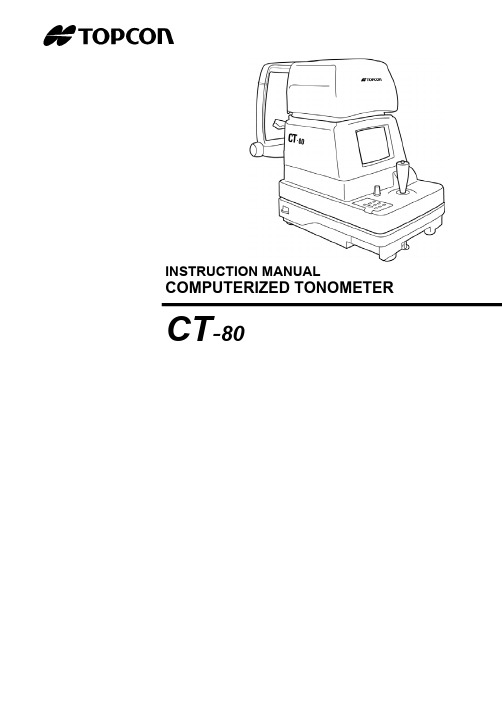
INSTRUCTION MANUAL COMPUTERIZED TONOMETER CT-80INTRODUCTIONThank you for purchasing the TOPCON Computer-ized Tonometer CT-80.(To get the best use from the instrument, please carefullyread these instructions and keep this Instruction Manual in a convenient location for future reference.)This instrument features the following:•An exact, non-contact intraocular pressure measurement that can be done by air ejection.•An alignment bar that enables easy operation.This text outlines the Computerized Tonometer CT-80 and de-scribes basic operations, troubleshooting, checking, maintenanceand cleaning.To encourage the safe, efficient use of this instrument and prevent danger to the operator and others, we suggest you carefully readthe “Displays for Safe Use” and the “Safety Cautions”.Again, please keep this Instruction Manual in a convenient locationfor future reference.Precautions•This machine is a precision instrument; install it in a place set to the fol-lowing conditions: temperature (10∼60°C), humidity (30∼85%) and atmos-pheric pressure (70∼106KPa). Avoid direct exposure to sunlight.•To ensure smooth operation, install the instrument on a level place free of vibrations. Also, do not place any objects on the instrument.•Before using the instrument, connect all cables correctly.•Use the specified source voltage.•When not in use, turn the power off and put the measuring window cap and dust cover on.•To ensure a correct reading, do not soil the measuring window with finger prints, dust, etc. Also, do not touch the measuring nozzle except whencleaning.1DISPLAY FOR SAFE USEIn order to encourage the safe use of the product and prevent any danger to the operator and others or damage to properties, important warnings are placed on the product and inserted in the instruction manual.We suggest that everyone understand the meaning of the following displays and icons before reading the “Safety Cautions” and text.• Injury refers to cuts, bruises, sprains, fractures, burn, electric shock, etc.• Physical damage refers to extensive damage to buildings or equipment and furniture.This icon indicates Hazard Alerting (Warning).Prohibition.Specific content is expressed with words or an icon either insert-ed in the icon itself or located next to the icon.This indicates Prohibition.Specific content is expressed with words or an icon either insert-ed in the icon itself or located next to the icon.This indicates Mandatory Action.Specific content is expressed with words or an icon either insert-ed in the icon itself or located next to the icon.2DISPLAY ICONS MEANINGWARNING CAUTIONMEANINGIgnoring or disregarding this display may lead to death or serious injury.Ignoring or disregarding this display may lead to personal injury or physical damage.SAFETY CAUTIONSIconsPrevention itemPageTo avoid electrical shock, do not open the instrument.Refer all servicing to qualified personnel.45To avoid electric shocks, do not remove the covers from the bottom and top surfaces, TV monitor, measuring unit, etc.45To prevent shock hazard, do not allow water or other foreign matter to enter into the instrument.—To avoid fire and electric shocks in case of tumbling, do not place a cup or vessel containing water/fluid on the instrument.—To avoid electric shocks, do not insert objects or metals through the vent holes or gaps or contain them inside the machine body.—To avoid electrical shock and fire, unplug the power cable before removing the fuse cover. Additionally, be sure to replace the fuse cover before plugging in the power cable.55Use only the attached fuses. Using other fuses may cause a fire.55Should any anomaly, such as smoke, occur, immediately switch OFF the power source and unplug the power cable.Continued use ignoring the condition may cause fire. Contact your dealer for repair.—3SAFETY CAUTIONS4USAGE AND MAINTENANCEPURPOSEThis tonometer “CT-80” is a precision electrical device for medical use that must be used under the instruction of a doctor.USER MAINTENANCETo maintain the safety and performance of the equipment, never attempt to do mainte-nance on your own. Ask our serviceman for repair except for the items specified here which can be maintained by the user. For details, follow the instructions.Fuse replacementThe primary fuses for the main body may be replaced by a non-trained service techni-cian. For details, refer to “Replacing the Fuse” on page 55.Cleaning of measuring windowCleaning of the measuring window glass is possible. For details, refer to the instruc-tions in “Cleaning the Measuring Window Glass” on page 52.Cleaning of window inside the nozzleCleaning of the window inside the nozzle is possible by following the instruction in “Cleaning the Window Glass inside the Nozzle” on page 53.ESCAPE CLAUSE•TOPCON shall not take any responsibility for damage due to fire, earthquakes, actions by a third party or other accidents, or the negligence and misuse of the user and use un-der unusual conditions.•TOPCON shall not take any responsibility for damage derived from the inability to use this equipment, such as a loss of business profit and suspension of business.•TOPCON shall not take any responsibility for damage caused by operations other than those described in this Instruction Manual.•Diagnoses shall be made on the responsibility of pertaining doctors and TOPCON shall not take any responsibility for the results of such diagnoses.5WARNING INDICATIONS AND POSITIONSTo ensure the safe usage of this equipment, precaution indications are provided.Abide by the following warning instructions. If any of the following labels are missing, please contact us at the address printed on the back cover of this manual.6CONTENTIntroduction1 Display for Safe Use2 Safety Cautions3 Usage and Maintenance5 Escape Clause5 Warning Indications and Positions6 NAMES OF COMPONENTS Main Body Components 8 Control Panel Components 9 Monitor Screen Components 10 Contents of Printer Output 11 Standard Accessories 12 PREPARATIONSHow to Install the Instrument13 How to Connect the Power Cable14 How to Connect External I/O Terminals14 Initial Settings15 How to Set Printer Paper23 How to Reset from Power Save Status28 BASIC OPERATIONS Preparations Before Measurement29 Measurement Under Auto Mode33 Measurement Under Manual Mode38 How to Delete Measurement Values41INDIVIDUAL OPERATIONS How to Print Out Measurement Values42How to Correct Measurement Values43Input/Output via RS-232C44 BEFORE REQUESTING SERV-ICEChecking Operations45 REFERENCEOptional Accessories46Specifications & Performance46RS-232C Communication Specifications47 MAINTENANCE AND CHECKINGAccuracy Maintenance52Special Notes on Cleaning567COMPONENTSMAIN BODY COMPONENTS8COMPONENTSMeasuring window capMeasuring headClamping knob Safety stopper knobControl panelExternal I/O terminalTV Monitor Measuring switch Control leverPower lamp Fixing knob (used to stop movements during removal)Power switch Power cable Adjusting knobForehead rest Measuring window Measuring nozzleHeight mark Chinrest pad pin Chinrest Chinrest handleCONTROL PANEL COMPONENTSPrint switch ...................Prints out the screen readings. When there is no reading, holdingthe switch down feeds the paper.Range switch ................Switches the range between 0-30 and 0-60.Clear switch ..................Deletes all the measurement values from the screen.Menu switch ..................Displays the Menu screen.Auto/Manual switch ......Switches the mode between auto and manual. Also, when se-lecting menu software, it moves the cursor right ().Air check switch ...........Performs an air check. Also, when selecting menu software, itmoves the cursor left ().Down switch .................When selecting menu software, it moves the cursor down ().Up switch .......................Range switch.When selecting menu software, it moves thecursor up ().9COMPONENTSPrint switchAuto/Manual switchClear switch Air check switchDown switchRange switch Menu switch Up switchSelect switchMONITOR SCREEN COMPONENTSMeasurement Screen (Auto mode, alignment)Measurement Screen (Manual mode, alignment OK)Menu Screen10COMPONENTSInner alignment markOuter alignment mark Alignment bar Alignment dotMeasuring range Measurement mode Target eyeInner alignment mark (alignment OK)CursorCONTENTS OF PRINTER OUTPUT11COMPONENTSAverage eye pressure valuesTime/Date displayWork ID No.Message columnMeasured eye pressurevalues ID No.Equipment No.Bar codeSTANDARD ACCESSORIESThe following are the standard accessories. The figures in parentheses are thequantities. Please check to see that all accessories are contained.Power cable (1)Rail cover (2)Printing paper (2)Chinrest pin (2)Chinrest pad (1)Silicone cloth (1)Dust cover (1)Fuse (2)* Different by destinationsCleaning kit (1)Instruction Manual, Unpacking and Assembly(1 each)Window glass cleaning procedure (1)12COMPONENTSPREPARATIONSHOW TO INSTALL THE INSTRUMENT1Fasten the clamping knob.2Hold the instrument body firmly at the specified positions and place it on the auto-matic instrument table.For the automatic instrument table, see “OPTIONAL ACCESSORIES” on page 46.3After installing the instrument, loosen the fixing knob.Now the body components can be moved.4If the machine body is slightly off level, properly turn the adjusters at the four corners for fine adjustment.Do not unscrew the adjusters more than 1cm.13PREPARATIONSBefore carrying the instrument, be sure to affix it firmly by turning the fixing screw at the base.If the instrument is moved with the screw loosened, it may result in damage to the instrument.CAUTIONWhen moving the instrument, be sure to hold it at the bottom surface with two people. Carrying by one person may cause back injury or injury by falling parts. Also, holding areas other than the bottom sur-face may cause pinching fingers between parts and injury by falling parts as well as damage to the instrument.CAUTIONTo avoid potential injury, hold the instrument in the proper position.CAUTIONHolding the instrumentSpecified holding positionsFixing knobHOW TO CONNECT THE POWER CABLE1Make sure the POWER SWITCH is OFF.2Attach the power cable to the machine body.3Plug the power cable into the 3-pin AC receptacle with grounding.HOW TO CONNECT EXTERNAL I/O TERMINALSRS-232C OUTThis machine can be connected to another device, including a personal computer via the RS-232C OUT terminal.1Connect the cable to the RS-232C OUT terminal of this machine.2Connect the other cable end to another device.RS-232C IN This machine can be connected to another device, including a bar code reader via the RS-232C IN terminal.1Connect the cable to the RS-232C IN terminal of this machine.2Connect the other cable end to the external device.14PREPARATIONSTo avoid electrical shock, do not handle the power plug with wet fingers.CAUTIONInput terminalOutput terminalINITIAL SETTINGSDuring the initial setting, date, time, operating time of the power save function, RS-232C, mode of average value, buzzer and message can be set.Preparations1Make sure the power cable is connected.For connection, see “HOW TO CONNECT THE POWER CABLE” on page 14.2Check the no-patient condition of the instrument and turn the POWER SWITCH ON. Displaying The Menu Screen1Make sure that the Measurement screen is displayed.2Press on the control panel.The Menu screen is displayed.Returning To The Measurement Screen1Press , on the control panel, move the cursor to “EXIT” and pressMEASUREMENT SWITCH .Or, press on the control panel. The Measurement screen returns.15PREPARATIONS•When the machine is moved from a cold room to a warm room orwhen the room temperature suddenly rises, it may cause dewing in-side the machine and disable measurement. In this case, leave themachine alone for about 30min until it reaches room temperature.MEMOTime/Date SettingExample of operation: Illustrations show time setting.1Press on the control panel to get the Menu screen.2Press,on the control panel, move the cursor to “DATE/TIME SET” andpress MEASUREMENT SWITCH .The Date/Time setting screen is displayed.3Make sure that the display “BATTERY → O.K.” appears.4Press,on the control panel, move the cursor to “HOUR” and pressMEASUREMENT SWITCH .16PREPARATIONSIf the display is “BATTERY → N.G.”, the built-in clock battery is used up. Contact your dealer. Additionally, when the battery becomes exhausted, time and date items are not printed and “DATE” is displayed instead.5of the control panel, renew figures and press .The renewed figures are inputted.6of the control panel, move the cursor to “EXIT” and pressSetting The Power Save TimeA time for the power save function to achvale can be selected from 10, 20, 30 or 60min.For shipment, 10min. is set.1Return to the Menu screen.2Press,on the control panel, move the cursor to “POWER SAVE TIME” andpress MEASUREMENT SWITCH . The Power Save Time Setting screen is displayed.3Press,on the control panel and change the power save time.17PREPARATIONSDate and other items can also be renewed at the same time.4Press MEASUREMENT SWITCH . The Menu screen is displayed.RS-232C INPUT/OUTPUT SettingsFor shipment, settings are EQUIPMENT (Equipment No.) No.1, FORMAT (communi-cation mode) OFF, and SPEED (communication speed) 2400Example: Setting the equipment No.1Return to the Menu screen.2Press,of the control panel, move the cursor to “RS-232C MODE” and pressMEASUREMENT SWITCH .The RS-232C Mode is displayed.18PREPARATIONSEach time , is pressed, the display changes as follows:3Press, on the control panel, move the cursor to “EQUIPMENT” and press MEASUREMENT SWITCH .4Press,on the control panel, change the equipment No. and pressMEASUREMENT SWITCH .5Press,on the control panel, move the cursor to “EXIT” and pressMEASUREMENT SWITCH . The Menu screen returns.19PREPARATIONS“EQUIPMENT” and “WORK ID NO.” can be reset by pressing .The equipment No.(EQUIPMENT) can be selected from 0000 to 0099. Each time ,is pressed, the display changes as follows:When setting the speed, the display changes from 2400-9600 each time ,ispressed.Setting The Average Value ModeThe average value display of the measurement values can be selected from integer anddecimal displays. For shipment, the integer display is set.1Return to the Menu screen.2Press , on the control panel, move the cursor to “AVERAGE MODE” and press MEASUREMENT SWITCH.The Average Value Mode screen is displayed.3Press , on the control panel to change the mode.20PREPARATIONS4Press MEASUREMENT SWITCH . The Menu screen returns.Setting The Buzzer The buzzer can be turned ON/OFF by pressing the switches on the control panel.1Return to the Menu screen.2Press , on the control panel, move the cursor to “BUZZER SET” and press MEASUREMENT SWITCH .The Buzzer Setting screen is displayed.3Press , on the control panel to select ON/OFF.21PREPARATIONS15:The average value is displayed as an integer (by rounding fractions to thenearest whole number).15.0:The average value is displayed up to one decimal (by rounding fractions to thenearest tenth).4Press MEASUREMENT SWITCH .The Menu screen returns.Message InputYou can add a brief message to the printout.1Return to the Menu screen.2Press , on the control panel, move the cursor to “MESSAGE INPUT” and press MEASUREMENT SWITCH .The Message Input screen is displayed.3Press , , , on the control panel to move the blinking icon to a character in the selection column for input.22PREPARATIONSSelection columnInput column4Press MEASUREMENT SWITCH .The character selected by the blinking icon is inputted.5Press , , , on the control panel, move the blinking icon in the selection column to “EXIT” and press MEASUREMENT SWITCH .The Menu screen is displayed.HOW TO SET PRINTER PAPERAuto Setting1Press the printer cover with your thumb, slide it aside and remove.23PREPARATIONS■: A space for 1 character (Use this to delete a character, too.)STEP : The blinking icon of the input column moves right.BACK : The blinking icon of the input column moves left.When the right/left end is reached, the blinking icon goes down to the next line.A message can contain up to 3 lines, 20 characters per line.Printer cover2Slide the paper roll onto the paper shaft, paying attention to the direction of unwind-ing, and pull out the top of the paper 7-8cm.3Insert the paper straight into the printer along the paper guide.4When the top of the paper stops inside the printer, press to further insert the paper into the printer.Paper feeding starts when the top of the paper reaches a certain depth inside the printer.5When the top of the paper comes out 1cm or so from the outlet, release .At this moment, hold the top of the paper firmly so that it is not rolled back.6Turn the paper retainer lever to the illustrated position, and pull out the paper 2-3cmso that it comes out straight from the outlet.24PREPARATIONS Unwinding directionPaper retainer lever7Return the paper retainer lever back to its original position.8Reset the printer cover, holding the top of the paper outside.25PREPARATIONSThe paper is not fed unless the paper retainer lever is lowered.Use the following 58mm wide printer paper:TF50KS-E2CUsing another paper may cause a printing noise or thin prints.Manual Setting1Press the printer cover with your thumb, slide it aside and remove.2Slide the paper roll onto the paper shaft, paying attention to the direction of unwind-ing, and pull out the top of the paper 7∼8cm.3Turn the paper retainer lever in the arrow direction.4Cut the paper on the control lever side at about 2cm.26PREPARATIONSPaper retainer leverControl leverCut here5Insert the paper straight into the printer along the paper guide.6Further insert the paper and draw out the top of the paper from the outlet.7Adjust the paper so that it comes out straight from the outlet, and then lower the pa-per retainer lever.27PREPARATIONSThe paper does not easily pass through the printer unless it is cut on the control lever side.8Set the printer cover, holding the top of the paper outside.HOW TO RESET FROM POWER SAVE STATUSThis machine employs a power save function. If the machine is not used during a set time, the power save function stops supplying power to the monitor and CCD camera.Under the power save status, the POWER lamp of the control panel flashes.1Press MEASUREMENT SWITCH .The Monitor screen is displayed in a few seconds, when the measurements become available.28PREPARATIONSIf the paper is jammed, turn the paper retainer lever to the illustrated position, and take out the jammed paper from the printer.After resetting, the measurement mode is AUTO and the measuring range is 0-30.Also, values measured before power saving are deleted.BASIC OPERATIONSPREPARATIONS BEFORE MEASUREMENT Turn ON the Power 1Make sure the power cable is connected.For connection, see “HOW TO CONNECT THE POWER CABLE” on page 14.2Make sure the instrument is in the no-patient condition and turn ON the POWER SWITCH .3The Title screen is displayed, and then the Measurement screen is displayed.Air Check This machine is equipped with a function for checking the correct operations measure-ment system inside the instrument.1Remove the measuring window cap.2Press on the control panel.Air is ejected from the measuring nozzle and checking is done automatically.3Make sure “OK” is displayed on the monitor screen. The Menu screen should be displayed a few seconds afterwards.29BASIC OPERATIONS Normal operation screenSetting the Patient1Return to the Measurement screen.2Ask the patient to sit in front of the instrument.3Adjust the automatic instrument table or the chair for height so that the patient can put his or her chin on the chinrest in a comfortable position.4The patient places his or her chin on the chinrest and stops his or her forehead at the forehead rest.If “NG (+)” or “NG (-)” is displayed, an anomaly has occurred. Turn OFF thePOWER SWITCH , and check whether or not there is any obstacle in front of the meas-uring nozzle. If there is an object, remove it, and then press the POWER SWITCH .Press and perform the checking procedure again.If no object is there, a problem has occurred. Turn OFF the POWER SWITCH , unplug the power cable, and call your dealer.Abnormal operation screen Never insert your fingers under the measuring head.∗ Inform the patient of this, too.Careless insertion of fingers may cause injury by pinching.CAUTION5 Adjust the height of the chinrest, by operating the chinrest handle, so that the tail of the patient's eye becomes level with the height mark of the chinrest post.Setting the Safety Stopper1Hold the control lever and pull the machine body towards the operator.2Turn the control lever and adjust the height of the measuring nozzle to the center of the patient's cornea.3While holding the safety stopper knob in a pressed position, hold the control lever and slowly push out the machine body.Before measuring, set the safety stopper. If the safetystopper is not set, it may cause injury to the eye that co-mes in contact with the measuring window glass. Set thesafety stopper separately for the right and left eyes.CAUTION When setting the safety stopper, do it from the instrumentside (safety stopper knob side).Setting from another position does not easily allow you tocheck the positions of the measuring window glass and thepatient's eye and may cause injury to the eye that comesin contact with the measuring window glass.CAUTION4When the measuring nozzle reaches a position 8∼10mm from the cornea, release the safety stopper knob.8∼10mm5Holding the control lever, try to slightly push out the machine body to make sure the stopper is working.If the machine body does not move forward any further, the setting is completed.MEASUREMENT UNDER AUTO MODE Setting the Measurement Mode The initial status of the measurement mode is AUTO, upon turning the power ON.1Return to the Measurement screen.2Presson the control panel and change the measurement mode display toAUTO.Setting the Measuring RangeIn this machine, the measuring range can be switched between 0-30 and 0-60.Normally, the 0-30 range is used, but if the patient's intraocular pressure is high, switch it to 0-60. The initial status of the measuring range is 0-30, upon turning the power ON.1Return to the Measurement screen.2Press on the control panel and make the measuring range display 0-30.• Adjust the height of the automatic instrument table so thatcorrect measurement values can be obtained by allowing the patient to undergo measurements in a comfortable position.• Make the patient relaxed so as to secure correct measure-ment values; make sure the patient does not hold his breathor remain tense.MEMOAlignment and MeasurementThe alignment operation can be performed with the control lever.• To move the measuring head vertically, turn the control lever right for raising and left for lowering.It is recommended that you do intraocular pressure measure-ments several times. Since the intraocular pressure varies byheart beats and tears, often it is not possible to obtain exactmeasurement values by measuring only once or twice.MEMOMoving the machine body by the control lever• When the machine body needs to be moved slightly back and forth or right and left,move the control lever in each direction.Operating the control lever(back and forth, right and left)Operating the control lever(up and down)Never insert your fingers under the measuring head.∗ Inform the patient of this, too.Careless insertion of fingers may cause injury by pinching.CAUTION1Hold the control lever and pull the machine body towards the operator.2Move the control lever in directions as needed and bring the patient’s eye to the center of the monitor screen.3Tell the patient to gaze at the yellow-green light.4Move the machine body toward the patient and focus the target eye. A vague alignment dot becomes seen reflected in the cornea.Inner alignment mark Alignment dot5Move the machine body in directions as needed in order to get the alignment dot within the inner alignment mark on the monitor screen.6Holding the alignment dot within the inner alignment mark, slightly push the machine body toward the patient.When the machine body approaches the target eye, the alignment bar and “FOR-WARD” display appear on the monitor screen.At this moment, be careful not to catch eyelashes and eyelids within the outer align-ment mark so as to ensure correct measurements.If the instrument is too close to the target eye, with regard to the alignment reference position, “TOO CLOSE” is displayed on the monitor screen, and if it is too far, “FOR-WARD” is displayed.The alignment bar is displayed as a broken line when the instrument is close to the target eye and as a solid line when it is far. Also, the alignment bar is shortened ac-cordingly as it approaches the alignment reference position.These factors are displayed only when the alignment dot is near the inner alignment mark.Alignment bar7After the alignment bar is displayed, push the machine body out a little bit more.When the alignment is adjusted, measurement is done automatically and the meas-urement value is displayed on the monitor screen.When the outer alignment mark is not displayed, measurement is not possible.Measurement can be done when the outer alignment mark is displayed after a few secondsReference positionToo farAfter measurement • If measurement is not possible under the Auto mode, usethe Manual mode. Sometimes Auto mode is not available ifthe condition of the cornea is unfavorable.MEMODisplay of Measurement Values Measurement values are displayed on the monitor screen for up to three measure-ments. From the fourth measurement on, values of earlier measurements are deleted in order.Figure only : Correct measurementFigure in ( ): Low in reliabilityERR : Incorrect measurementOVER : Measurement value exceeding the measuring rangeMEASUREMENT UNDER MANUAL MODESetting the Measurement ModeThe initial status of the measurement mode is AUTO, upon turning the power ON.1Return to the Measurement screen.2Presson the control panel and change the measurement mode display to“MANU”.Setting the Measuring RangeSee page 33.Alignment and MeasurementThe alignment operation is controlled through the control lever.For details about the adjustment of the machine body using the control lever, see “Memo” on page 34.If the result is a figure in parentheses or ERR, do the measurement again, making sure the patient does not blink and eyelashes do not get in the outer alignment mark.If OVER is displayed, switch the measuring range to 0-60 and do the measurement again.• Adjust the height of the automatic instrument table so that correctmeasurement values can be obtained by allowing the patient to un-dergo measurements in a comfortable position.• Make the patient relaxed so as to secure correct measurement val-ues; make sure the patient does not hold his breath or remain tense.MEMO。
拓普康CT80说明书-中英文

RS-232C 方式屏显示出来。
18
3.按控制面板上的U、V钮,把光标移动到“EQUIPMENT”,再按测量键。 4.按控制面板上的U、V钮,更改设备号,再按测量键。
可在 0000 至 0099 范围内选择设备号(EQUIPMENT)。 每次按下U、V钮,显示变化如下: 设定速度时,每次按下U、V钮,显示值在 2400 至 9600 间变化。 按下 钮就可重新设定“EQUIPMENT”和“WORK ID NO.”。
1.确认电源线已正确连接。 关于此连接请阅读第 14 页的“连接电源线”。
2.检查仪器的状况,打开电源开关(ON)。 仪器从寒冷的房间移动至温暖的房间,或室温
注意事项 突然升高时,可使仪器内产生露水,影响测量。
在这种情况下,把仪器放在那里大约 30 分钟, 直到它的温度和室温一样时再开机。 显示菜单屏 1.确认测量屏显示出来了。 2.按控制面板上的 钮。 菜单屏显示出来。 返回测量屏 1.按控制面板上的U、V钮,把光标移动到“EXIT”,再按测量键。
* 伤害包括损伤、烧伤、电击等。 * 设施损坏指的是对建筑物、设备和房内陈设的损坏。
图标的含义 图标
含义
它指的是必须执行的动作。 具体内容用紧贴图标的文字或图样表达。
它代表警告。 具体内容用紧贴图标的文字或图样表达。
它代表禁止。 具体内容用紧贴图标的文字或图样表达。
2
安全注意事项
警告
图标
注意事项
页
17
3.按控制面板上的U、V钮,更改节能时间。
每次按下U、V钮,时间显示变化如下: 5 ↔ 10 ↔ 20 ↔ 30 ↔ 60
4.按测量键。测量屏显示出来。 RS-232C 输入、输出设定
出厂时,设定为 EQUIPMENT(设备号)No.1,FORMAT(传输方式)OFF, SPEED(传输速度)2400 实例:设定设备号 1. 返回菜单屏 2.按控制面板上的U、V钮,把光标移动到“RS-232C MODE”,再按测
CT扩散炉培训教材(设备中英文版)

建议选择(B) Process recipe has terminated with error state AC Ongoing process to end the error status ――― Alarm confirmation To store To store enable unload Restart recipe A―― Used the wrong process number , Hand end of the process , Start a
5.舟位于存储架(storage2,3)时,一定要确认存储架上 的感应器有没有感应到,否则有可能导致撞舟。
When the boat is located on the storage rack (storage2, 3),make sure that the storage rack sensor is sensed, otherwise may cause the bumped boat. 6.从手动切换自动时,Grip一定要在Middle位置,
料箱 3、Toxic gases
有毒气体排放 4、Furnace
炉体 5、Gas box
气源柜
Loading wafer 加栽的硅片
Baddle head 舟头
Mechanica l arm 机械臂
Storage rack 1,2 存储位1、2
Paddle bearing, adjustable paddle position 碳化硅桨支座,调节桨位置
Information button
4 Current display area in the 10 system mode
Philips PerfectCare Compact Centro de planchado说明书

Philips PerfectCare CompactCentro de planchadoPresión máxima de la bomba de 6,5 baresGolpe de vapor de hasta 420g Depósito de agua con capacidad de 1,5 lBloqueo de seguridadGC7846/80Planchado más rápido con el doble de vapor* Nuestro generador de vapor más compactoEl potente vapor continuo permite terminar el planchado de forma rápida, sin necesidad de ajustar la temperatura gracias a nuestra tecnología OptimalTEMP. Compacto y ligero para facilitar su uso y almacenamiento.Tecnología Compact•Depósito grande para un uso prolongado•Apagado automático cuando la plancha se deja desatendida•Ligera y compacta para un uso y almacenamiento sencillos•Bloqueo de seguridad para un transporte fácil y seguroNo requiere ajustes de temperatura, sin quemaduras: garantizado•Seguro en todas las prendas que se pueden planchar. Sin quemaduras, garantizado•Tecnología OptimalTEMP, no requiere ajustes de temperaturaPlanchado rápido con chorro de vapor potente y continuo•Ahorro de energía con el modo ECO•Depósito con función Calc-Clean incluido: sin cartuchos ni coste adicional•La suela SteamGlide resistente a los arañazos ofrece un buen deslizamiento•Potente chorro de vapor para eliminar las arrugas de forma definitivaVapor ultrapotente El potente y continuo chorro de vapor puede incluso con los tejidos más gruesos con total facilidad. Observa cómo las arrugas rebeldes desaparecen con un golpe de vapor adicional justo donde lo necesitas. Este vapor adicional es perfecto para planchar en vertical y también para refrescar la ropa y las cortinas.Sin necesidad de ajustes de temperaturaPlancha cualquier prenda, desde vaqueros hasta seda, sin ajustar la temperatura. Gracias a OptimalTEMP, no necesitarás utilizar botones ni realizar ajustes. Ya no tendrás que preclasificar las prendas para hacer la colada, niesperar a que la plancha se caliente y se enfríe. Estarás preparado para planchar cualquiertejido en cualquier momento.Sin quemaduras: garantizadoGracias a tecnología OptimalTEMP, garantizamos que esta plancha nunca quemará los tejidos que se pueden planchar. Puedes incluso dejarla directamente sobre la ropa o la tabla de planchar. Sin quemaduras ni brillos. Garantizado.Depósito de agua de 1,5 lUn depósito transparente de 1,5 litros teofrece 1,5 horas de uso continuo. Podrás ver claramente la cantidad de agua que queda y volver a llenarlo fácilmente bajo el grifo a través de la gran compuerta de llenado.Eliminación inteligente de la cal Nuestro sistema Smart Calc-Clean integradote recuerda cuando es necesario eliminar los depósitos de cal. Incluye un depósito para eliminar los depósitos con más facilidad. Esto significa que no se necesitan cartuchos y no hay ningún coste adicional.Ahorro de energía Ahorra energía y obtén los mismos excelentes resultados. El modo ECO reduce el consumo de energía para las prendas que requieran menos vapor.Compactos y cómodos Su peso ligero y tamaño compacto son perfectos para el almacenamiento, y hacen que se ajuste perfectamente a la tabla de planchar. La exclusiva tecnología ProVelocity hace que nuestros generadores de vapor sean más pequeños y compactos que nunca.Fecha de emisión 2023-05-20Versión: 2.2.1EAN: 87 10103 93587 2© 2023 Koninklijke Philips N.V.Todos los derechos reservados.Las especificaciones están sujetas a cambios sin previo aviso. Las marcas registradas son propiedad de Koninklijke Philips N.V. o de sus propietarios respectivos.Almacenamiento•Bloqueo de seguridad: Para el transporte y la seguridad•Recogecable: Sujeción con velcro •Compartimento de la manguera: Compartimento para guardar la mangueraConsumer Trade Item•Height:27.6•Width: 23•Length: 39.3•Net Weight:3.3•Gross Weight: 3.935•GTIN: 08710103935872•Country of origin: ID•Harmonized system code: 85164000 Facilidad de uso•Seguro en todos los tejidos que se puedan planchar: Incluso en tejidos delicados como la seda •Capacidad del depósito de agua: 1500 ml •Deslizamiento perfecto de la suela: 3 estrellas •Nombre de la suela: SteamGlide•Apagado de seguridad•Llenado en cualquier momento durante el uso •Cable giratorio: Cable con giro de 180 grados •Apta para el uso con agua del grifo•Longitud del cable de alimentación: 1,8 m •Longitud de la manguera de vapor: 1,6 m •Enchufe de alimentación integrado•Punta de vapor de precisión•Lista para usar: Indicador luminoso, Indicador de sonido•Suela resistente a los arañazos: 4 estrellas Accesorios incluidos•Depósito Calc-CleanGarantía•2 años de garantía mundial Tecnología•Tecnología OptimalTEMP•Para todos los tejidos que se puedan planchar•Sin quemaduras•Sin necesidad de ajustes de temperatura•Generador de vapor ProVelocity•Procesador de control inteligenteEliminación rápida de las arrugas•Presión: máxima de la bomba de 6,5 bares•Potencia: 2400 W•Golpe de vapor: Hasta 420 g•Salida de vapor continuo: Hasta 120 g/min.•Tensión: 220-240 V•Vapor vertical•Niveles variables de vapor•Lista para usar:2 minute(s)•Vapor personalizadoEficiencia ecológica•Modo de ahorro de energía•Ahorro de energía*: 30 %•Uso de plástico reciclado: 30 %•Manual del usuario: Papel 100 % recicladoGestión de escala•Eliminación de los depósitos de cal y limpieza:Smart Calc-Clean•Recordatorio de eliminación de la cal: Vista, Oído,Sin cartuchos ni coste adicionalTamaño y peso•Dimensiones del embalaje (An. x Al. x Pr.):23 x 27,5 x 39,3 cm•Peso de la plancha: 1,2 kg•Dimensiones del producto (An. x Al. x Pr.):19,3 x 22,3 x 37,3 cm•Peso total con el embalaje: 3,85 kg•Peso de la plancha + base: 2,95 kg*Ahorro de energía de hasta un 30 % con el modo ECO encomparación con el modo Turbo según IEC 60311*En comparación con la plancha de vapor Azur de Philips。
- 1、下载文档前请自行甄别文档内容的完整性,平台不提供额外的编辑、内容补充、找答案等附加服务。
- 2、"仅部分预览"的文档,不可在线预览部分如存在完整性等问题,可反馈申请退款(可完整预览的文档不适用该条件!)。
- 3、如文档侵犯您的权益,请联系客服反馈,我们会尽快为您处理(人工客服工作时间:9:00-18:30)。
3
注意
图标
注意事项
页
为避免受伤,搬动仪器时请把持正确的位置。
13
为避免触电,不要用湿手拿电源插头。
14
不要把手放在测量头下。
*让病人知道这一点。
29
无意之中把手放在那里,有可能因挤压而受伤。
不要把手放在测量头下。
*让病人知道这一点。
33
无意之中把手放在那里,有可能因挤压而受伤。
不要在仪器附近使用喷雾清洁剂。
* 伤害包括损伤、烧伤、电击等。 * 设施损坏指的是对建筑物、设备和房内陈设的损坏。
图标的含义 图标
含义
它指的是必须执行的动作。 具体内容用紧贴图标的文字或图样表达。
它代表警告。 具体内容用紧贴图标的文字或图样表达。
它代表禁止。 具体内容用紧贴图标的文字或图样表达。
2
安全注意事项
警告
图标
注意事项
页
菜单开关…………………… 显示菜单屏。 自动、手动选择开关……… 在自动和手动方式间转换。 初始化开关………………. 测量头返回原始位置。 向下开关…………………… 选择菜单屏时,它可使光标向下移动(T)。 向上开关…………………… 选择菜单屏时,它可使光标向上移动(S)。
9
显示器屏幕
测量屏幕(自动方式,对准)
1.确认电源线已正确连接。 关于此连接请阅读第 14 页的“连接电源线”。
2.检查仪器的状况,打开电源开关(ON)。 仪器从寒冷的房间移动至温暖的房间,或室温
注意事项 突然升高时,可使仪器内产生露水,影响测量。
在这种情况下,把仪器放在那里大约 30 分钟, 直到它的温度和室温一样时再开机。 显示菜单屏 1.确认测量屏显示出来了。 2.按控制面板上的 钮。 菜单屏显示出来。 返回测量屏 1.按控制面板上的U、V钮,把光标移动到“EXIT”,再按测量键。
目标眼 测量方式 测量范围
对准点
测量屏幕(手动方式,已对准好)
菜单屏幕
光标
10
外对准标记 对准条 内对准标记
外对准标记 内对准标记(已对准好)
打印内容
仪器号码 ID 号码
测量眼压力值 信息栏
条形码 工作 ID 号码 时间、日期显示 平均眼压力值
11
标准附件
以下是标准附件。括号中的数字代表数量,请检查是否所有附件都在。
17
3.按控制面板上的U、V钮,更改节能时间。
每次按下U、V钮,时间显示变化如下: 5 ↔ 10 ↔ 20 ↔ 30 ↔ 60
4.按测量键。测量屏显示出来。 RS-232C 输入、输出设定
出厂时,设定为 EQUIPMENT(设备号)No.1,FORMAT(传输方式)OFF, SPEED(传输速度)2400 实例:设定设备号 1. 返回菜单屏 2.按控制面板上的U、V钮,把光标移动到“RS-232C MODE”,再按测
调整钮旋出超过 1 厘米。
13
连接电源线
注意
为避免触电,不要用湿手拿电源插头。
1 确认电源开关已关闭。 2 将电源线与主体连接。
3 把电源线插头插入接地的三针交流电源插座。
连接外部输入、输出接口
RS-232C 输出 因为有 RS-232C 接口,此仪器能同个人电脑等设备相连接。 1.把连接线一端同此仪器的 RS-232C OUT(输出)接口相连接。 2.把连接线的另一端同个人电脑等相连接。
注意事项 z 这是一台精密仪器,请在如下正常生活环境下安装:温度(10~60 摄氏度),
湿度(30~85%),气压(70~106kPa)。避免直接暴露在阳光下。 z 为了正常操作,不要在不平或有震动的地方安装此仪器。不要把任何东西放
在仪器上。 z 使用前要正确连接所有电线。 z 要使用规定的电压。 z 仪器不工作时,请关闭电源并盖上测量窗罩和防尘罩。 z 为确保正确测量,不要让手指印、尘土等沾污测量窗,并且除了做清洁工作
注意
为避免伤害患者,不要用仪器 接触病人的眼睛和鼻子。
警告
触电可引起灼伤或火灾。更换保 险丝前要关闭电源,并拔下电源 插头。更换时,只能用同样规格 的保险丝。
6
目录
前言 警告标记 安全注意事项 使用和保养 免责条款 警告标记及其位置
名称 主体部件 控制面板部件 显示器屏幕 打印内容 标准附件
准备 安装仪器 连接电源线 连接外部输入、输出接口 初始设置 安装打印纸 从节能状态重新启动
27
28 32 38 41
7
名称
主体部件
测量头
锁紧钮 安全制动钮
控制面板 外部输入\输出接口
电源开关 电源线 调整钮
8
显示器 测量键 操作手柄
电源显示灯
紧固螺钉(搬运时用)
前额托 测量窗口 测量喷嘴 高度标记 颌托垫销 下颌托 下颌托调节钮
测量窗罩
控制面板部件
菜单键
范围设定键
打印开关
清除开关
选择开关
电源线(1)
轨道盖板(2)
打印纸(2)
下颌托纸销(2)
下颌托垫(1)
清洁布(1)
保险丝(2) *因国家地区而异
防尘罩(1)
清洁盒(1)
组装说明书、使用说明书各一份
测量窗玻璃清洁步骤表(1)
12
准备
安装仪器
注意 注意
搬运仪器前,要钮紧底座上的紧固螺钉。 否则,仪器可移动并导致损坏。
搬运仪器时,一定要有两个人托住它的底部。一人搬运可 能造成背部损伤或被落下的部件砸伤。不托底部而抓着其 它部位,有可能使手指挤压在零件当中或被落下的部件砸 伤,仪器也可能损坏。
5
警告标记及其位置
为保证此设备的安全使用,我们提供了警告标志。 请听从如下警告。如果以下任何标签丢失,请与 TOPCON 公司联系。
警告
为避免触电,不要拆卸仪器。 请求有资格的人员为您服务。
注意
为避免伤害患者,操作前要 确认安全制动钮已起作用。
警告
为避免触电,不要拆卸仪器。 请求有资格的人员为您服务。
用其它化学品有可能在测量中对病人的眼睛造成伤害。
54
4
使用和保养
使用
CT-80A 眼压计是一部医用精密电子设备,必须在医生指导下使用。
用户保养
为保证仪器的安全和效能,除此说明书允许的操作,其它保养工作只 能由专业工程师完成。下面的保养工作可由用户来做。关于保养方法 请阅读此说明书中有关章节。 z 更换保险丝 主体的第一、第二保险丝可由用户更换。 详细情况,请阅读第 56 页的“更换保险丝”。 z 清洁测量窗 可以清洁测量窗玻璃。 详细情况,请阅读第 53 页的“清洁测量窗玻璃”。 z 清洁喷嘴里面的窗口 可以清洁喷嘴里面的窗口。 详细情况,请阅读第 54 页的“清洁喷嘴里面的窗口玻璃”。
量键。
RS-232C 方式屏显示出来。
18
3.按控制面板上的U、V钮,把光标移动到“EQUIPMENT”,再按测量键。 4.按控制面板上的U、V钮,更改设备号,再按测量键。
可在 0000 至 0099 范围内选择设备号(EQUIPMENT)。 每次按下U、V钮,显示变化如下: 设定速度时,每次按下U、V钮,显示值在 2400 至 9600 间变化。 按下 钮就可重新设定“EQUIPMENT”和“WORK ID NO.”。
16
5.按控制面板上的U、V钮,更新数字,再按测量键。 更新的数字被输入。
6.按控制面板上的U、V钮,把光标移动到“EXIT”,再按测量键。 日期和其它项也能同时更新。
设定节能时间 可以选择 10、20、30 或 60 分钟后节能功能发挥作用。 出厂设定为 10 分钟。 1.返回菜单屏。 2.按控制面板上的U、V钮,把光标移动到“POWER SAVE TIME”,再按 测量键。节能时间设定屏显示出来。
向下开关
自动/手动开关
初始化开关 向上开关
打印开关…………………… 打印出屏幕上显示的测量记录。没有测量记录时 按下此钮可送纸。
范围开关…………………… 在 0~30 和 0~60 范围间转换。选择菜单屏时,可 使光标向左移动(W)。
清除开关…………………… 清除屏幕上所有测量值。选择菜单屏时,可使 光标向右移动(X)。
如果有一滴清洁剂停留在测量喷嘴中,在测量中病人的眼睛可 57 能受伤。
搬运仪器前,要钮紧底座上的紧固螺钉。
13
否则,仪器可移动并导致损坏。
搬运仪器时,一定要有两个人托住它的底部。一人搬运可能造
成背部损伤或被落下的部件砸伤。不托底部而抓着其它部位,
有可能使手指挤压在零件当中或被落下的部件砸伤,仪器也可 13 能损坏。
基本操作 测量前的准备 自动测量 手动测量 删除测量值
1
其它操作
2
打印测量值
42
3
补偿测量值
43
5
RS-232C 的输入、输出
44
5
6
请求服务之前
检查
45
8
参考资料
9
可选附件
47
10
规格和性能
47
11
RS-232C 的传输规格
48
12 保养和检查
精心维护
53
13
清洁时的特别注意事项
57
14
14
15
23
测量键
测量键
或者按控制面板上期 操作实例:时间设定图示。 1.按控制面板上的 钮。菜单屏显示出来。 2.按控制面板上的U、V钮,把光标移动到“DATE/TIME SET”, 再按测量键。
日期、时间设定屏显示出来。 3.确认“BATTERY → O.K”出现。
如果显示出“BATTERY → N.G.”,说明内置时钟电池没电了。请与您 的销售商联系。另外,电池用尽时,不能打印时间和日期,“DATE” (日期)显示出来。 4.按控制面板上的U、V钮,把光标移动到“HOUR”,再按测量键。