汽车制动器毕业设计翻译
汽车制动系统-毕业设计外文资料翻译

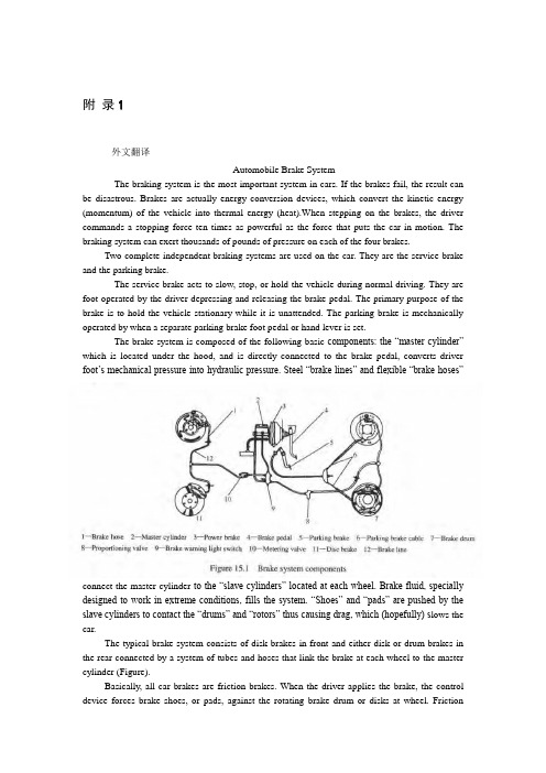
Automobile Brake SystemThe braking system is the most important system in cars. If the brakes fail, theresult can be disastrous. Brakes are actually energy conversion devices, whichconvert the kinetic energy (momentum) of the vehicle into thermal energy(heat).When stepping on the brakes, the driver commands a stopping force tentimes as powerful as the force that puts the car in motion. The braking systemcan exert thousands of pounds of pressure on each of the four brakes.Two complete independent braking systems are used on the car. They are theservice brake and the parking brake.The service brake acts to slow, stop, or hold the vehicle during normal driving.They are foot-operated by the driver depressing and releasing the brake pedal.The primary purpose of the parking brake is to hold the vehicle stationary whileit is unattended. The parking brake is mechanically operated by when a separateparking brake foot pedal or hand lever is set.The brake system is composed of the following basic c omponents: the “master cylinder” which is located under the hood, and is directly connected to the brake pedal, converts driver foot’s mechanical pressure into hydraulic pressure. Steel “brake lines” and flexible “brake hoses” connect the master cylinder to the cylinders” located at each wheel. Brake fluid, specially designed to work inextreme conditions, fills the system. “Shoes” and “pads” are pushed by cylinders to contact the “drums” and “rotors” thus causing drag, which (hopefully) slows the car.The typical brake system consists of disk brakes in front and either disk ordrum brakes in the rear connected by a system of tubes and hoses that link thebrake at each wheel to the master cylinder (Figure).Basically, all car brakes are friction brakes. When the driver applies the brake, the control device forces brake shoes, or pads, against the rotating brake drum or disks at wheel. Friction between the shoes or pads and the drums or disks then slows or stops the wheel so that the car is braked.In most modern brake systems (see Figure 15.1), there is a fluid-filled cylinder, called master cylinder, which contains two separate sections, there is a piston in each section and both pistons are connected to a brake pedal in the driver compartment. When the brake is pushed down, brake fluid is sent from the master cylinder to the wheels.At the wheels, the fluid pushes shoes, or pads, against revolving drums or disks. The friction between the stationary shoes, or pads, and the revolving drums or disks slows and stops them. This slows or stops the revolving wheels, which, in turn, slow or stop the car.The brake fluid reservoir is on top of the master cylinder. Most cars todayhave a transparent reservoir so that you can see the level without opening the cover. The brake fluid level will drop slightly as the brake pads wear. This is a normal condition and no cause for concern. If the level drops noticeably over ashort period of time or goes down to about two thirds full, have your brakes checked as soon as possible. Keep the reservoir covered except for the amount of time you need to fill it and never leave a cam of brake fluid uncovered. Brakefluid must maintain a very high boiling point. Exposure to air will cause the fluidto absorb moisture which will lower that boiling point.The brake fluid travels from the master cylinder to the wheels through a seriesof steel tubes and reinforced rubber hoses. Rubber hoses are only used in places that require flexibility, such as at the front wheels, which move up and down as well as steer. The rest of the system uses non-corrosive seamless steel tubing with special fittings at all attachment points. If a steel line requires a repair, thebest procedure is to replace the compete line. If this is not practical, a line can be repaired using special splice fittings that are made for brake system repair. You must never use copper tubing to repair a brake system. They are dangerous and illegal.Drum brakes, it consists of the brake drum, an expander, pull back springs, a stationary back plate, two shoes with friction linings, and anchor pins. The stationary back plate is secured to the flange of the axle housing or to thesteering knuckle. The brake drum is mounted on the wheel hub. There is a clearance between the inner surface of the drum and the shoe lining. To apply brakes, the driver pushes pedal, the expander expands the shoes and presses them to the drum. Friction between the brake drum and the friction linings brakes the wheels and the vehicle stops. To release brakes, the driver release the pedal, the pull back spring retracts the shoes thus permitting free rotation of the wheels.Disk brakes, it has a metal disk instead of a drum. A flat shoe, or disk-brake pad,is located on each side of the disk. The shoes squeeze the rotatin g disk to stopthe car. Fluid from the master cylinder forces the pistons to move in, toward the disk. This action pushes the friction pads tightly against the disk. The friction between the shoes and disk slows and stops it. This provides the braking action. Pistons are made of either plastic or metal. There are three general types of disk brakes. They are the floating-caliper type, the fixed-caliper type, and thesliding-caliper type. Floating-caliper and sliding-caliper disk brakes use a single piston. Fixed-caliper disk brakes have either two or four pistons.The brake system assemblies are actuated by mechanical, hydraulic or pneumatic devices. The mechanical leverage is used in the parking brakes fittedin all automobile. When the brake pedal is depressed, the rod pushes the pistonof brake master cylinder which presses the fluid. The fluid flows through the pipelines to the power brake unit and then to the wheel cylinder. The fluidpressure expands the cylinder pistons thus pressing the shoes to the drum or disk.If the pedal is released, the piston returns to the initialposition, the pull backsprings retract the shoes, the fluid is forced back to the master cylinder andbraking ceases.The primary purpose of the parking brake is to hold the vehicle stationary whileit is unattended. The parking brake is mechanically operated by the driver when a separate parking braking hand lever is set. The hand brake is normally usedwhen the car has already stopped. A lever is pulled and the rear brakes are approached and locked in the “on” position. The car may now be left without fear of its rolling away. When the driver wants to move the car again, he mustpress a button before the lever can be released. The hand brake must also be ableto stop the car in the event of the foot brake failing. For this reason, it is separatefrom the foot brake uses cable or rods instead of the hydraulic system.Anti-lock Brake SystemAnti-lock brake systems make braking safer and more convenient, Anti-lockbrake systems modulate brake system hydraulic pressure to prevent the brakesfrom locking and the tires from skidding on slippery pavement or during a panicstop.Anti-lock brake systems have been used on aircraft for years, and some domesticcar were offered with an early form of anti-lock braking in late 1990’s. Recently, several automakers have introduced more sophisticated anti-lock system. Investigations in Europe, where anti-lock brakin g systems have been availablefor a decade, have led one manufacture to state that the number of trafficaccidents could be reduced by seven and a half percent if all cars had anti-lock brakes. So some sources predict that all cars will offer anti-lock brakes toimprove the safety of the car.Anti-lock systems modulate brake application force several times per second tohold the tires at a controlled amount of slip; all systems accomplish this inbasically the same way. One or more speed sensors generate alternating currentsignal whose frequency increases with the wheel rotational speed. An electroniccontrol unit continuously monitors these signals and if the frequency of a signaldrops too rapidly indicating that a wheel is about to lock, the control unitinstructs a modulating device to reduce hydraulic pressure to the brake at theaffected wheel. When sensor signals indicate the wheel is again rotatingnormally, the control unit allows increased hydraulic pressure to the brake. Thisrelease-a pply cycle occurs several time per second to “pump” the brakes like driver might but at a much faster rate.In addition to their basic operation, anti-lock systems have two other things incommon. First, they do not operate until the brakes are applied with enoughforce to lock or nearly lock a wheel. At all other times, the system stands readyto function but does not interfere with normal braking. Second, if the anti-locksystem fail in any way, the brakes continue to operate without anti-lockcapability. A warning light on the instrument panel alerts the driver when aproblem exists in the anti-lock system.The current Bosch component Anti-lock Braking System (ABSⅡ), is a second generation design wildly used by European automakers such as BWM,Mercedes-Benz and Porsche. ABSⅡ system consists of : four wheel speedsensor, electronic control unit and modulator assembly.A speed sensor is fitted at each wheel sends signals about wheel rotation tocontrol unit. Each speed sensor consists of a sensor unit and a gear wheel. Thefront sensor mounts to the steering knuckle and its gear wheel is pressed onto thestub axle that rotates with the wheel. The rear sensor mounts the rear suspension member and its gear wheel is pressed onto the axle. The sensor itself is awinding with a magnetic core. The core creates a magnetic field around the winding, and as the teeth of the gear wheel move through this field, an alternating current is induced inthe winding. The control unit monitors the rate o change in this frequency to determine impending brake lockup.divided into three parts: signal processing,The control unit’s function can belogic and safety circuitry. The signal processing section is the converter that receives the alternating current signals form the speed sensors and converts them into digital form for the logic section. The logic section then analyzes thedigitized signals to calculate any brake pressure changes needed. If impending lockup is sensed, the logic section sends commands to the modulator assembly. Modulator assemblyThe hydraulic modulator assembly regulates pressure to the wheel brakes when it receives commands from the control utuit. The modulator assembly can maintain or reduce pressure over the level it receives from the master cylinder, it also can never apply the brakes by itself. The modulator assembly consists of threehigh-speed electric solenoid valves, two fluid reservoirs and a turn deliverypump equipped with inlet and outlet check valves. The modulator electrical connector and controlling relays are concealed under a plastic cover of the assembly.Each front wheel is served by electric solenoid valve modulated independentlyby the control unit. The rear brakes are served by a single solenoid valve and modulated together using the select-low principle. During anti-braking system operation, the control unit cycles the solenoid valves to either hold or release pressure the brake lines. When pressure is released from the brake lines during anti-braking operation, it is routed to a fluid reservoir. There is one reservoir for the front brake circuit. The reservoirs are low-pressure accumulators that storefluid under slight spring pressure until the return delivery pump can return the fluid through the brake lines to the master cylinder.汽车制动系统制动系统是汽车上最重要的系统。
汽车制动系统(机械、车辆工程毕业论文英文文献及翻译)
Automobile Brake SystemThe braking system is the most important system in cars. If the brakes fail, the result can be disastrous. Brakes are actually energy conversion devices, which convert the kinetic energy (momentum) of the vehicle into thermal energy (heat).When stepping on the brakes, the driver commands a stopping force ten times as powerful as the force that puts the car in motion. The braking system can exert thousands of pounds of pressure on each of the four brakes.Two complete independent braking systems are used on the car. They are the service brake and the parking brake.The service brake acts to slow, stop, or hold the vehicle during normal driving. They are foot-operated by the driver depressing and releasing the brake pedal. The primary purpose of the brake is to hold the vehicle stationary while it is unattended. The parking brake is mechanically operated by when a separate parking brake foot pedalor hand lever is set.The brake system is composed of the following basic components: the “master cylinder” which is located under the hood, and is directly connected to the brake pedal, converts driver foot’s mechanical pressure into hydraulic pressure. Steel “brake lines” and flexible “brake hoses” connect the master cylinder to the “slave cylinders” located at each wheel. Brake fluid, specially designed to work in extreme conditions, fills the system. “Shoes” and “pads” are pushed by the slave cylinders to contact the “drums” and “rotors” thus causing drag, which (hopefully) slows the car.The typical brake system consists of disk brakes in front and either disk or drum brakes in the rear connected by a system of tubes and hoses that link the brake at each wheel to the master cylinder (Figure).Basically, all car brakes are friction brakes. When the driver applies the brake, the control device forces brake shoes, or pads, against the rotating brake drum or disks at wheel. Friction between the shoes or pads and the drums or disks then slows or stops the wheel so that the car is braked.In most modern brake systems (see Figure 15.1), there is a fluid-filled cylinder, called master cylinder, which contains two separate sections, there is a piston in each section and both pistons are connected to a brake pedal in the driver’s compartment. When the brake is pushed down, brake fluid is sent from the master cylinder to the wheels.At the wheels, the fluid pushes shoes, or pads, against revolving drums or disks. The friction between the stationary shoes, or pads, and the revolving drums or disks slows and stops them. This slows or stops the revolving wheels, which, in turn, slow or stop the car.The brake fluid reservoir is on top of the master cylinder. Most cars today have a transparent r reservoir so that you can see the level without opening the cover. The brake fluid level will drop slightly as the brake pads wear. This is a normal condition and no cause for concern. If the level drops noticeably over ashort period of time or goes down to about two thirds full, have your brakes checked as soon as possible. Keep the reservoir covered except for the amount of time you need to fill it and never leave a cam of brake fluid uncovered. Brake fluid must maintain a very high boiling point. Exposure to air will cause the fluid to absorb moisture which will lower that boiling point.The brake fluid travels from the master cylinder to the wheels through a series of steel tubes and reinforced rubber hoses. Rubber hoses are only used in places that require flexibility, such as at the front wheels, which move up and down as well as steer. The rest of the system uses non-corrosive seamless steel tubing with special fittings at all attachment points. If a steel line requires a repair, the best procedure is to replace the compete line. If this is not practical, a line can be repaired using special splice fittings that are made for brake system repair. You must never use copper tubing to repair a brake system. They are dangerous and illegal.Drum brakes, it consists of the brake drum, an expander, pull back springs, a stationary back plate, two shoes with friction linings, and anchor pins. The stationary back plate is secured to the flange of the axle housing or to the steering knuckle. The brake drum is mounted on the wheel hub. There is a clearance between the inner surface of the drum and the shoe lining. To apply brakes, the driver pushes pedal, the expander expands the shoes and presses them to the drum. Friction between the brake drum and the friction linings brakes the wheels and the vehicle stops. To releaseAnti-lock brake systems make braking safer and more convenient, Anti-lock brake systems modulate brake system hydraulic pressure to prevent the brakes from locking and the tires from skidding on slippery pavement or during a panic stop.Anti-lock brake systems have been used on aircraft for years, and some domestic car were offered with an early form of anti-lock braking in late 1990’s. Recently, several automakers have introduced more sophisticated anti-lock system. Investigations in Europe, where anti-lock brakin g systems have been available for a decade, have led one manufacture to state that the number of traffic accidents could be reduced by seven and a half percent if all cars had anti-lock brakes. So some sources predict that all cars will offer anti-lock brakes to improve the safety of the car.Anti-lock systems modulate brake application force several times per second to hold the tires at a controlled amount of slip; all systems accomplish this in basically the same way. One or more speed sensors generate alternating current signal whose frequency increases with the wheel rotational speed. An electronic control unit continuously monitors these signals and if the frequency of a signal drops too rapidly indicating that a wheel is about to lock, the control unit instructs a modulating device to reduce hydraulic pressure to the brake at the affected wheel. When sensor signals indicate the wheel is again rotating normally, the control unit allows increased hydraulic pressure to the brake. This release-apply cycle occurs several time per second to “pump” the brakes like a driver might but a t a much faster rate.In addition to their basic operation, anti-lock systems have two other things in common. First, they do not operate until the brakes are applied with enough force to lock or nearly lock a wheel. At all other times, the system stands ready to function but does not interfere with normal braking. Second, if the anti-lock system fail in any way, the brakes continue to operate without anti-lock capability. A warning light on the instrument panel alerts the driver when a problem exists in the anti-lock system.The current Bosch component Anti-lock Braking System (ABSⅡ), is a second generation design wildly used by European automakers such as BWM,Mercedes-Benz and Porsche. ABSⅡsystem consists of : four wheel speed sensor, electronic control unit and modulator assembly.A speed sensor is fitted at each wheel sends signals about wheel rotation to control unit. Each speed sensor consists of a sensor unit and a gear wheel. The front sensor mounts to the steering knuckle and its gear wheel is pressed onto the stub axle that rotates with the wheel. The rear sensor mounts the rear suspension member and its gear wheel is pressed onto the axle. The sensor itself is a winding with a magnetic core. The core creates a magnetic field around the winding, and as the teeth of the gear wheel move through this field, an alternating current is induced in the winding. The control unit monitors the rate o change in this frequency to determine impending brake lockup.The control unit’s function can be divided into three parts: signal processing, logic and safety circuitry. The signal processing section is the converter that receives the alternating current signals form the speed sensors and converts them into digital form for the logic section. The logic section then analyzes the digitized signals to calculate any brake pressure changes needed. If impending lockup is sensed, the logic section sends commands to the modulator assembly.Modulator assemblyThe hydraulic modulator assembly regulates pressure to the wheel brakes when it receives commands from the control utuit. The modulator assembly can maintain or reduce pressure over the level it receives from the master cylinder, it also can never apply the brakes by itself. The modulator assembly consists of three high-speed electric solenoid valves, two fluid reservoirs and a turn delivery pump equipped with inlet and outlet check valves. The modulator electrical connector and controlling relays are concealed under a plastic cover of the assembly.Each front wheel is served by electric solenoid valve modulated independently by the control unit. The rear brakes are served by a single solenoid valve and modulated together using the select-low principle. During anti-braking system operation, the control unit cycles the solenoid valves to either hold or release pressure the brake lines. When pressure is released from the brake lines during anti-braking operation, it is routed to a fluid reservoir. There is one reservoir for the front brake circuit. The reservoirs are low-pressure accumulators that store fluid under slight spring pressure until the return delivery pump can return the fluid through the brake lines to the master cylinder.汽车制动系统制动系统是汽车中最重要的系统。
汽车制动毕业设计
【摘要】本说明书主要介绍了汽车制动的设计探索,先绍了汽车制动系统的设计意义、研究现状以及设计目标。
然后解释了制动器的主要类型并对制动系统进行方案论证分析与选择,主要包括制动器形式方案分析、制动驱动机构的机构形式选择、液压分路系统的形式选择和液压制动主缸的设计方案,最后确定方案采用简单人力液压制动双回路前后盘式制动器。
除此之外,还根据已知的汽车相关参数,通过计算得到了制动器主要参数、前后制动力矩分配系数、制动力矩和制动力以及液压制动驱动机构相关参数。
最后对制动性能进行了详细分析。
关键词:制动系统盘式制动器液压AbstractThis manual mainly introduces the design of the car brake exploration, occupying first automobile brake system design significance, research status and design target. And then explain the main types of brake system and project demonstration analysis and choice, mainly including brake form, braking scheme analysis drive agencies of choice of optical system, hydraulic form in the form of choice and hydraulic brake main cylinder, the design of the final determination scheme adopts simple human hydraulic brake double loop around disc brakes. In addition, also related parameters according to the known car, through the main parameters calculated, the front brake torque distribution coefficient, braking torque and power system and hydraulic brake driven related parameters. Finally the brake performance are analyzed in detail.Key words: Braking system Disc brakes hydraulic1.绪论 (5)1.1制动系统设计的意义 (5)1.2制动系统研究现状 (5)1.3本次制动系统应达到的目标 (5)1.4汽车制动规则和要求 (5)1.4.1 制动系统——概况 (6)1.4.2 制动测试 (6)1.4.3 刹车踏板超程开关 (6)1.4.4 刹车灯 (6)2.制动系统概述 (6)2.1分类与组成 (7)2.2制动系统的一般工作原理 (7)2.3制动器 (9)2.3.1鼓式制动器 (9)2.3.2盘式制动器 (12)2.4人力制动系统 (15)2.4.1机械制动系统 (15)2.4.2人力液压制动系统 (15)2.5伺服制动系 (16)2.5.1助力式伺服制动系 (17)2.5.2增压式伺服制动系 (18)2.6动力制动系统 (18)2.6.1气压制动系统 (19)2.7气顶液制动系与全液压动力制动系 (19)2.7.1 气顶液制动系 (19)2.7.2全液压动力制动系 (20)3.制动系统设计计算 (20)3.1制动系统主要参数数值 (20)3.1.1 相关主要参数 (20)3.1.2 同步附着系数的分析 (1)3.1.3地面对前、后轮的法向反作用力 (1)3.2制动器有关计算 (1)3.2.1 确定前后制动力矩分配系数 (1)3.2.2 制动器制动力矩的确定 (1)3.2.3 盘式制动器主要参数确定 (1)3.2.4 盘式制动器的制动力计算 (1)3.3制动器主要零部件的结构设计 (1)4.液压制动驱动机构的设计计算 (1)4.1前轮制动轮缸直径的确定 (1)4.2制动主缸直径的确定 (1)4.3制动踏板力和制动踏板工作行程 (1)5. 制动性能分析 (1)5.1制动性能评价指标 (1)5.2制动效能 (1)5.3制动效能的恒定性 (1)5.4制动时汽车方向的稳定性 (1)5.5制动器制动力分配曲线分析 (1)5.6制动减速度和制动距离S (1)5.7摩擦衬块的磨损特性计算 (1)参考文献 (3)结束语 ...................................................................................................................... 错误!未定义书签。
(完整版)汽车制动系统英文文献及翻译)

Automobile Brake SystemThe braking system is the most important system in cars. If the brakes fail, the result can be disastrous. Brakes are actually energy conversion devices, which convert the kinetic energy (momentum) of the vehicle into thermal energy (heat).When stepping on the brakes, the driver commands a stopping force ten times as powerful as the force that puts the car in motion. The braking system can exert thousands of pounds of pressure on each of the four brakes.Two complete independent braking systems are used on the car. They are the service brake and the parking brake.The service brake acts to slow, stop, or hold the vehicle during normal driving. They are foot-operated by the driver depressing and releasing the brake pedal. The primary purpose of the brake is to hold the vehicle stationary while it is unattended. The parking brake is mechanically operated by when a separate parking brake foot pedal or hand lever is set.The brake system is composed of the following basic components: t he “master cylinder” which is located under the hood, and is directly connected to the brake pedal, converts driver foot’s mechanical pressure into hydraulic pressure. Steel “brake lines” and flexible “brake hoses” connect the master cylinder to the “slave cylinders” located at each wheel. Brake fluid, specially designed to work in extreme conditions, fills the system. “Shoes” and “pads” are pushed by the slave cylinders to contact the “drums” and “rotors” thus causing drag, which (hopefully) slows the car.The typical brake system consists of disk brakes in front and either disk or drum brakes in the rear connected by a system of tubes and hoses that link the brake at each wheel to the master cylinder (Figure).Basically, all car brakes are friction brakes. When the driver applies the brake, the control device forces brake shoes, or pads, against the rotating brake drum or disks at wheel. Friction between the shoes or pads and the drums or disks then slows or stops the wheel so that the car is braked.In most modern brake systems (see Figure 15.1), there is a fluid-filled cylinder, called master cylinder, which contains two separate sections, there is a piston in each section and both pistons are connected to a brake pedal in the driver’s compartment. When th e brake is pushed down, brake fluid is sent from the master cylinder to the wheels.At the wheels, the fluid pushes shoes, or pads, against revolving drums or disks. The friction between the stationary shoes, or pads, and the revolving drums or disks slows and stops them. This slows or stops the revolving wheels, which, in turn, slow or stop the car.The brake fluid reservoir is on top of the master cylinder. Most cars today have a transparent r reservoir so that you can see the level without opening the cover. The brake fluid level will drop slightly as the brake pads wear. This is a normal condition and no cause for concern. If the level drops noticeably over ashort period of time or goes down to about two thirds full, have your brakes checked as soon as possible. Keep the reservoir covered except for the amount of time you need to fill it and never leave a cam of brake fluid uncovered. Brake fluid must maintain a very high boiling point. Exposure to air will cause the fluid to absorb moisture which will lower that boiling point.The brake fluid travels from the master cylinder to the wheels through a series of steel tubes and reinforced rubber hoses. Rubber hoses are only used in places that require flexibility, such asat the front wheels, which move up and down as well as steer. The rest of the system uses non-corrosive seamless steel tubing with special fittings at all attachment points. If a steel line requires a repair, the best procedure is to replace the compete line. If this is not practical, a line can be repaired using special splice fittings that are made for brake system repair. You must never use copper tubing to repair a brake system. They are dangerous and illegal.Drum brakes, it consists of the brake drum, an expander, pull back springs, a stationary back plate, two shoes with friction linings, and anchor pins. The stationary back plate is secured to the flange of the axle housing or to the steering knuckle. The brake drum is mounted on the wheel hub. There is a clearance between the inner surface of the drum and the shoe lining. To apply brakes, the driver pushes pedal, the expander expands the shoes and presses them to the drum. Friction between the brake drum and the friction linings brakes the wheels and the vehicle stops. To release brakes, the driver release the pedal, the pull back spring retracts the shoes thus permitting free rotation of the wheels.Disk brakes, it has a metal disk instead of a drum. A flat shoe, or disk-brake pad, is located on each side of the disk. The shoes squeeze the rotatin g disk to stop the car. Fluid from the master cylinder forces the pistons to move in, toward the disk. This action pushes the friction pads tightly against the disk. The friction between the shoes and disk slows and stops it. This provides the braking action. Pistons are made of either plastic or metal. There are three general types of disk brakes. They are the floating-caliper type, the fixed-caliper type, and the sliding-caliper type. Floating-caliper and sliding-caliper disk brakes use a single piston. Fixed-caliper disk brakes have either two or four pistons.The brake system assemblies are actuated by mechanical, hydraulic or pneumatic devices. The mechanical leverage is used in the parking brakes fitted in all automobile. When the brake pedal is depressed, the rod pushes the piston of brake master cylinder which presses the fluid. The fluid flows through the pipelines to the power brake unit and then to the wheel cylinder. The fluid pressure expands the cylinder pistons thus pressing the shoes to the drum or disk. If the pedal is released, the piston returns to the initialposition, the pull back springs retract the shoes, the fluid is forced back to the master cylinder and braking ceases.The primary purpose of the parking brake is to hold the vehicle stationary while it is unattended. The parking brake is mechanically operated by the driver when a separate parking braking hand lever is set. The hand brake is normally used when the car has already stopped. A lever is pulled and t he rear brakes are approached and locked in the “on” position. The car may now be left without fear of its rolling away. When the driver wants to move the car again, he must press a button before the lever can be released. The hand brake must also be able to stop the car in the event of the foot brake failing. For this reason, it is separate from the foot brake uses cable or rods instead of the hydraulic system.Anti-lock Brake SystemAnti-lock brake systems make braking safer and more convenient, Anti-lock brake systems modulate brake system hydraulic pressure to prevent the brakes from locking and the tires from skidding on slippery pavement or during a panic stop.Anti-lock brake systems have been used on aircraft for years, and some domestic car were offered with an early form of anti-lock braking in late 1990’s. Recently, several automakers have introduced more sophisticated anti-lock system. Investigations in Europe, where anti-lock brakin g systems have been available for a decade, have led one manufacture to state that the number oftraffic accidents could be reduced by seven and a half percent if all cars had anti-lock brakes. So some sources predict that all cars will offer anti-lock brakes to improve the safety of the car.Anti-lock systems modulate brake application force several times per second to hold the tires at a controlled amount of slip; all systems accomplish this in basically the same way. One or more speed sensors generate alternating current signal whose frequency increases with the wheel rotational speed. An electronic control unit continuously monitors these signals and if the frequency of a signal drops too rapidly indicating that a wheel is about to lock, the control unit instructs a modulating device to reduce hydraulic pressure to the brake at the affected wheel. When sensor signals indicate the wheel is again rotating normally, the control unit allows increased hydraulic pressure to the brake. This release-apply cycle occurs several time per second to “pump” the brakes like a dr iver might but at a much faster rate.In addition to their basic operation, anti-lock systems have two other things in common. First, they do not operate until the brakes are applied with enough force to lock or nearly lock a wheel. At all other times, the system stands ready to function but does not interfere with normal braking. Second, if the anti-lock system fail in any way, the brakes continue to operate without anti-lock capability. A warning light on the instrument panel alerts the driver when a problem exists in the anti-lock system.The current Bosch component Anti-lock Braking System (ABSⅡ), is a second generation design wildly used by European automakers such as BWM, Mercedes-Benz and Porsche. ABSⅡsystem consists of : four wheel speed sensor, electronic control unit and modulator assembly.A speed sensor is fitted at each wheel sends signals about wheel rotation to control unit. Each speed sensor consists of a sensor unit and a gear wheel. The front sensor mounts to the steering knuckle and its gear wheel is pressed onto the stub axle that rotates with the wheel. The rear sensor mounts the rear suspension member and its gear wheel is pressed onto the axle. The sensor itself is a winding with a magnetic core. The core creates a magnetic field around the winding, and as the teeth of the gear wheel move through this field, an alternating current is induced in the winding. The control unit monitors the rate o change in this frequency to determine impending brake lockup.The control unit’s functi on can be divided into three parts: signal processing, logic and safety circuitry. The signal processing section is the converter that receives the alternating current signals form the speed sensors and converts them into digital form for the logic section. The logic section then analyzes the digitized signals to calculate any brake pressure changes needed. If impending lockup is sensed, the logic section sends commands to the modulator assembly.Modulator assemblyThe hydraulic modulator assembly regulates pressure to the wheel brakes when it receives commands from the control utuit. The modulator assembly can maintain or reduce pressure over the level it receives from the master cylinder, it also can never apply the brakes by itself. The modulator assembly consists of three high-speed electric solenoid valves, two fluid reservoirs and a turn delivery pump equipped with inlet and outlet check valves. The modulator electrical connector and controlling relays are concealed under a plastic cover of the assembly.Each front wheel is served by electric solenoid valve modulated independently by the control unit. The rear brakes are served by a single solenoid valve and modulated together using the select-low principle. During anti-braking system operation, the control unit cycles the solenoid valves to either hold or release pressure the brake lines. When pressure is released from the brakelines during anti-braking operation, it is routed to a fluid reservoir. There is one reservoir for the front brake circuit. The reservoirs are low-pressure accumulators that store fluid under slight spring pressure until the return delivery pump can return the fluid through the brake lines to the master cylinder.汽车制动系统制动系统是汽车中最重要的系统。
汽车制动系统英文文献及翻译

汽车制动系统-英文文献及翻译————————————————————————————————作者:————————————————————————————————日期:Brake systemsWe all know that pushing down on the brake pedal slows a car to a stop. But how does this happen? How does your car transmit the force from your leg to its wheels? How does it multiply the force so that it is enough to stop something as big as a car?Brake Image GalleryLayout of typical brake system. See more brake images.When you depress your brake pedal, your car transmits the force from your foot to its brakes through a fluid. Since the actual brakes require a much greater force than you could apply with your leg, your car must also multiply the force of your foot. It does this in two ways:•Mechanical advantage (leverage)•Hydraulic force multiplicationThe brakes transmit the force to the tires using friction, and the tires transmit that force to the road using friction also. Before we begin our discussion on the components of the brake system, we'll cover these three principles:•Leverage•Hydraulics•FrictionLeverage and HydraulicsIn the figure below, a force F is being applied to the left end of the lever. The left end of the lever is twice as long (2X) as the right end (X). Therefore, on the right end of the lever a force of 2F is available, but it acts through half of the distance (Y) that the left end moves (2Y). Changing the relative lengths of the left and right ends of the lever changes the multipliers.The pedal is designed in such a way that it can multiply the force from yourleg several times before any force is even transmitted to the brake fluid.The basic idea behind any hydraulic system is very simple: Force applied at one point is transmitted to another point using an incompressible fluid, almost always an oil of some sort. Most brake systems also multiply the force in the process. Here you can see the simplest possible hydraulic system:Your browser does not support JavaScript or it is disabled.Simple hydraulic systemIn the figure above, two pistons (shown in red) are fit into two glass cylinders filled with oil (shown in light blue) and connected to one another with an oil-filled pipe. If youapply a downward force to one piston (the left one, in this drawing), then the force is transmitted to the second piston through the oil in the pipe. Since oil is incompressible, the efficiency is very good -- almost all of the applied force appears at the second piston. The great thing about hydraulic systems is that the pipe connecting the two cylinders can be any length and shape, allowing it to snake through all sorts of things separating the twopistons. The pipe can also fork, so that one master cylinder can drive more than one slave cylinder if desired, as shown in here:Your browser does not support JavaScript or it is disabled.Master cylinder with two slavesThe other neat thing about a hydraulic system is that it makes force multiplication (or division) fairly easy. If you have read How a Block and Tackle Works or How Gear Ratios Work, then you know that trading force for distance is very common in mechanical systems. In a hydraulic system, all you have to do is change the size of one piston and cylinder relative to the other, as shown here:Your browser does not support JavaScript or it is disabled.Hydraulic multiplicationTo determine the multiplication factor in the figure above, start by looking at the size of the pistons. Assume that the piston on the left is 2 inches (5.08 cm) in diameter (1-inch / 2.54 cm radius), while the piston on the right is 6 inches (15.24 cm) in diameter (3-inch / 7.62 cm radius). The area of the two pistons is Pi * r2. The area of the left piston is therefore 3.14, while the area of the piston on the right is 28.26. The piston on the right is nine times larger than the piston on the left. This means that any force applied to theleft-hand piston will come out nine times greater on the right-hand piston. So, if you apply a 100-pound downward force to the left piston, a 900-pound upward force will appear on the right. The only catch is that you will have to depress the left piston 9 inches (22.86 cm) to raise the right piston 1 inch (2.54 cm).A Simple Brake SystemBefore we get into all the parts of an actual car brake system, let's look at a simplified system:Your browser does not support JavaScript or it is disabled.A simple brake systemYou can see that the distance from the pedal to the pivot is four times the distance from the cylinder to the pivot, so the force at the pedal will be increased by a factor of four before it is transmitted to the cylinder.You can also see that the diameter of the brake cylinder is three times the diameter of the pedal cylinder. This further multiplies the force by nine. All together, this system increases the force of your foot by a factor of 36. If you put 10 pounds of force on the pedal, 360 pounds (162 kg) will be generated at the wheel squeezing the brake pads.There are a couple of problems with this simple system. What if we have a leak? If it is a slow leak, eventually there will not be enough fluid left to fill the brake cylinder, and the brakes will not function. If it is a major leak, then the first time you apply the brakes all of the fluid will squirt out the leak and you will have complete brake failure.Drum brakes work on the same principle as disc brakes: Shoes press against a spinning surface. In this system, that surface is called a drum.Figure 1. Location of drum brakes. See more drum brakepictures.Many cars have drum brakes on the rear wheels and disc brakes on the front. Drum brakes have more parts than disc brakes and are harder to service, but they are less expensive to manufacture, and they easily incorporate an emergency brake mechanism.In this edition of HowStuffWorks, we will learn exactly how a drum brake system works, examine the emergency brake setup and find out what kind of servicing drum brakes need.Figure 2. Drum brake with drum in placeFigure 3. Drum brake without drum in placeLet's start with the basics.The Drum BrakeThe drum brake may look complicated, and it can be pretty intimidating when you open one up. Let's break it down and explain what each piece does.Figure 4. Parts of a drum brakeLike the disc brake, the drum brake has two brake shoes and a piston. But the drum brake also has an adjuster mechanism, an emergency brake mechanism and lots of springs.First, the basics: Figure 5 shows only the parts that provide stopping power.Your browser does not support JavaScript or it isdisabled.Figure 5. Drum brake in operationWhen you hit the brake pedal, the piston pushes the brake shoes against the drum. That's pretty straightforward, but why do we need all of those springs?This is where it gets a little more complicated. Many drum brakes are self-actuating. Figure 5 shows that as the brake shoes contact the drum, there is a kind of wedging action, which has the effect of pressing the shoes into the drum with more force.The extra braking force provided by the wedging action allows drum brakes to use a smaller piston than disc brakes. But, because of the wedging action, the shoes must be pulled away from the drum when the brakes are released. This is the reason for some of the springs. Other springs help hold the brake shoes in place and return the adjuster arm after it actuates.Brake AdjusterFor the drum brakes to function correctly, the brake shoes must remain close to the drum without touching it. If they get too far away from the drum (as the shoes wear down, for instance), the piston will require more fluid to travel that distance, and your brake pedal will sink closer to the floor when you apply the brakes. This is why most drum brakes have an automatic adjuster.Figure 6. Adjuster mechanismNow let's add in the parts of the adjuster mechanism. The adjuster uses theself-actuation principle we discussed above.Your browser does not support JavaScript or it is disabled.Figure 7. Drum brake adjuster in operationIn Figure 7, you can see that as the pad wears down, more space will form between the shoe and the drum. Each time the car stops while in reverse, the shoe is pulled tight against the drum. When the gap gets big enough, the adjusting lever rocks enough to advance the adjuster gear by one tooth. The adjuster has threads on it, like a bolt, so that it unscrews a little bit when it turns, lengthening to fill in the gap. When the brake shoes wear a little more, the adjuster can advance again, so it always keeps the shoes close to the drum.Some cars have an adjuster that is actuated when the emergency brake is applied. This type of adjuster can come out of adjustment if the emergency brake is not used forlong periods of time. So if you have this type of adjuster, you should apply your emergency brake at least once a week.ServicingThe most common service required for drum brakes is changing the brake shoes. Some drum brakes provide an inspection hole on the back side, where you can see how much material is left on the shoe. Brake shoes should be replaced when the friction material has worn down to within 1/32 inch (0.8 mm) of the rivets. If the friction material is bonded to the backing plate (no rivets), then the shoes should be replaced when they have only 1/16 inch (1.6 mm) of material left.Photo courtesy of a local AutoZone storeFigure 9. Brake shoeJust as in disc brakes, deep scores sometimes get worn into brake drums. If aworn-out brake shoe is used for too long, the rivets that hold the friction material to the backing can wear grooves into the drum. A badly scored drum can sometimes be repaired by refinishing. Where disc brakes have a minimum allowable thickness, drum brakes have a maximum allowable diameter. Since the contact surface is the inside of the drum, as you remove material from the drum brake the diameter gets bigger.Figure 10. Brake drum制动系统众所周知,踩下制动踏板可以使汽车减速至停止。
汽车制动系统中英文对照外文翻译文献
汽车制动系统中英文对照外文翻译文献(文档含英文原文和中文翻译)Brake systemsWe all know that pushing down on the brake pedal slows a car to a stop. But how does this happen? How does your car transmit the force from your leg to its wheels? How does it multiply the force so that it is enough to stop something as big as a car?Brake Image GalleryLayout of typical brake system. See more brake images.When you depress your brake pedal, your car transmits the force from your foot to its brakes through a fluid. Since the actual brakes require a much greater force than you could apply with your leg, your car must also multiply the force of your foot. It does this in two ways:∙Mechanical advantage (leverage)∙Hydraulic force multiplicationThe brakes transmit the force to the tires using friction, and the tires transmit that force to the road using friction also. Before we begin our discussion on the components of the brake system, we'll cover these three principles:∙Leverage∙Hydraulics∙FrictionLeverage and HydraulicsIn the figure below, a force F is being applied to the left end of the lever. The left end of the lever is twice as long (2X) as the right end (X). Therefore, on the right end of the lever a force of 2F is available, but it acts through half of the distance (Y) that the left end moves (2Y). Changing the relative lengths of the left and right ends of the lever changes the multipliers.The pedal is designed in such a way that it can multiply the force from yourleg several times before any force is even transmitted to the brake fluid.The basic idea behind any hydraulic system is very simple: Force applied at one point is transmitted to another point using an incompressible fluid, almost always an oil of some sort. Most brake systems also multiply the force in the process. Here you can see the simplest possible hydraulic system:Your browser does not support JavaScript or it is disabled.Simple hydraulic systemIn the figure above, two pistons (shown in red) are fit into two glass cylinders filled with oil (shown in light blue) and connected to one another with an oil-filled pipe. If youapply a downward force to one piston (the left one, in this drawing), then the force is transmitted to the second piston through the oil in the pipe. Since oil is incompressible, the efficiency is very good -- almost all of the applied force appears at the second piston. The great thing about hydraulic systems is that the pipe connecting the two cylinders can be any length and shape, allowing it to snake through all sorts of things separating the twopistons. The pipe can also fork, so that one master cylinder can drive more than one slave cylinder if desired, as shown in here:Your browser does not support JavaScript or it is disabled.Master cylinder with two slavesThe other neat thing about a hydraulic system is that it makes force multiplication (or division) fairly easy. If you have read How a Block and Tackle Works or How Gear Ratios Work, then you know that trading force for distance is very common in mechanical systems. In a hydraulic system, all you have to do is change the size of one piston and cylinder relative to the other, as shown here:Your browser does not support JavaScript or it is disabled.Hydraulic multiplicationTo determine the multiplication factor in the figure above, start by looking at the size of the pistons. Assume that the piston on the left is 2 inches (5.08 cm) in diameter (1-inch / 2.54 cm radius), while the piston on the right is 6 inches (15.24 cm) in diameter (3-inch / 7.62 cm radius). The area of the two pistons is Pi * r2. The area of the left piston is therefore 3.14, while the area of the piston on the right is 28.26. The piston on the right is nine times larger than the piston on the left. This means that any force applied to theleft-hand piston will come out nine times greater on the right-hand piston. So, if you apply a 100-pound downward force to the left piston, a 900-pound upward force will appear on the right. The only catch is that you will have to depress the left piston 9 inches (22.86 cm) to raise the right piston 1 inch (2.54 cm).A Simple Brake SystemBefore we get into all the parts of an actual car brake system, let's look at a simplified system:Your browser does not support JavaScript or it is disabled.A simple brake systemYou can see that the distance from the pedal to the pivot is four times the distance from the cylinder to the pivot, so the force at the pedal will be increased by a factor of four before it is transmitted to the cylinder.You can also see that the diameter of the brake cylinder is three times the diameter of the pedal cylinder. This further multiplies the force by nine. All together, this system increases the force of your foot by a factor of 36. If you put 10 pounds of force on the pedal, 360 pounds (162 kg) will be generated at the wheel squeezing the brake pads.There are a couple of problems with this simple system. What if we have a leak? If it is a slow leak, eventually there will not be enough fluid left to fill the brake cylinder, and the brakes will not function. If it is a major leak, then the first time you apply the brakes all of the fluid will squirt out the leak and you will have complete brake failure.Drum brakes work on the same principle as disc brakes: Shoes press against a spinning surface. In this system, that surface is called a drum.Figure 1. Location of drum brakes. See more drum brakepictures.Many cars have drum brakes on the rear wheels and disc brakes on the front. Drum brakes have more parts than disc brakes and are harder to service, but they are less expensive to manufacture, and they easily incorporate an emergency brake mechanism.In this edition of HowStuffWorks, we will learn exactly how a drum brake system works, examine the emergency brake setup and find out what kind of servicing drum brakes need.Figure 2. Drum brake with drum in placeFigure 3. Drum brake without drum in placeLet's start with the basics.The Drum BrakeThe drum brake may look complicated, and it can be pretty intimidating when you open one up. Let's break it down and explain what each piece does.Figure 4. Parts of a drum brakeLike the disc brake, the drum brake has two brake shoes and a piston. But the drum brake also has an adjuster mechanism, an emergency brake mechanism and lots of springs.First, the basics: Figure 5 shows only the parts that provide stopping power.Your browser does not support JavaScript or it is disabled.Figure 5. Drum brake in operationWhen you hit the brake pedal, the piston pushes the brake shoes against the drum. That's pretty straightforward, but why do we need all of those springs?This is where it gets a little more complicated. Many drum brakes are self-actuating. Figure 5 shows that as the brake shoes contact the drum, there is a kind of wedging action, which has the effect of pressing the shoes into the drum with more force.The extra braking force provided by the wedging action allows drum brakes to use a smaller piston than disc brakes. But, because of the wedging action, the shoes must be pulled away from the drum when the brakes are released. This is the reason for some of the springs. Other springs help hold the brake shoes in place and return the adjuster arm after it actuates.Brake AdjusterFor the drum brakes to function correctly, the brake shoes must remain close to the drum without touching it. If they get too far away from the drum (as the shoes wear down, for instance), the piston will require more fluid to travel that distance, and your brake pedal will sink closer to the floor when you apply the brakes. This is why most drum brakes have an automatic adjuster.Figure 6. Adjuster mechanismNow let's add in the parts of the adjuster mechanism. The adjuster uses theself-actuation principle we discussed above.Your browser does not support JavaScript or it is disabled.Figure 7. Drum brake adjuster in operationIn Figure 7, you can see that as the pad wears down, more space will form between the shoe and the drum. Each time the car stops while in reverse, the shoe is pulled tight against the drum. When the gap gets big enough, the adjusting lever rocks enough to advance the adjuster gear by one tooth. The adjuster has threads on it, like a bolt, so that it unscrews a little bit when it turns, lengthening to fill in the gap. When the brake shoes wear a little more, the adjuster can advance again, so it always keeps the shoes close to the drum.Some cars have an adjuster that is actuated when the emergency brake is applied. This type of adjuster can come out of adjustment if the emergency brake is not used forlong periods of time. So if you have this type of adjuster, you should apply your emergency brake at least once a week.ServicingThe most common service required for drum brakes is changing the brake shoes. Some drum brakes provide an inspection hole on the back side, where you can see how much material is left on the shoe. Brake shoes should be replaced when the friction material has worn down to within 1/32 inch (0.8 mm) of the rivets. If the friction material is bonded to the backing plate (no rivets), then the shoes should be replaced when they have only 1/16 inch (1.6 mm) of material left.Photo courtesy of a local AutoZone storeFigure 9. Brake shoeJust as in disc brakes, deep scores sometimes get worn into brake drums. If aworn-out brake shoe is used for too long, the rivets that hold the friction material to the backing can wear grooves into the drum. A badly scored drum can sometimes be repaired by refinishing. Where disc brakes have a minimum allowable thickness, drum brakes have a maximum allowable diameter. Since the contact surface is the inside of the drum, as you remove material from the drum brake the diameter gets bigger.Figure 10. Brake drum制动系统众所周知,踩下制动踏板可以使汽车减速至停止。
汽车制动系统英文文献及翻译)
Automobile Brake SystemThe braking system is the most important system in cars. If the brakes fail, the result can be disastrous. Brakes are actually energy conversion devices, which convert the kinetic energy (momentum) of the vehicle into thermal energy (heat).When stepping on the brakes, the driver commands a stopping force ten times as powerful as the force that puts the car in motion. The braking system can exert thousands of pounds of pressure on each of the four brakes.Two complete independent braking systems are used on the car. They are the service brake and the parking brake.The service brake acts to slow, stop, or hold the vehicle during normal driving. They are foot-operated by the driver depressing and releasing the brake pedal. The primary purpose of the brake is to hold the vehicle stationary while it is unattended. The parking brake is mechanically operated by when a separate parking brake foot pedal or hand lever is set.The brake system is composed of the following basic components: t he “master cylinder” which is located under the hood, and is directly connected to the brake pedal, converts driver foot’s mechanical pressure into hydraulic pressure. Steel “brake lines” and flexible “brake hoses” connect the master cylinder to the “slave cylinders” located at each wheel. Brake fluid, specially designed to work in extreme conditions, fills the system. “Shoes” and “pads” are pushed by the slave cylinders to contact the “drums” and “rotors” thus causing drag, which (hopefully) slows the car.The typical brake system consists of disk brakes in front andeither disk or drum brakes in the rear connected by a system of tubesand hoses that link the brake at each wheel to the master cylinder (Figure).Basically, all car brakes are friction brakes. When the driver applies the brake, the control device forces brake shoes, or pads, against the rotating brake drum or disks at wheel. Friction between the shoes or pads and the drums or disks then slows or stops the wheel sothat the car is braked.In most modern brake systems (see Figure 15.1), there is a fluid-filled cylinder, called master cylinder, which contains two separate sections, there is a piston in each section and both pistons are connected to a brake pedal in the driver’s compartme nt. When th e brake is pushed down, brake fluid is sent from the master cylinder to the wheels.At the wheels, the fluid pushes shoes, or pads, against revolving drums or disks. The friction between the stationary shoes, or pads, and the revolving drums or disks slows and stops them. This slows or stops the revolving wheels, which, in turn, slow or stop the car.The brake fluid reservoir is on top of the master cylinder. Most cars today have a transparent r reservoir so that you can see the level without opening the cover. The brake fluid level will drop slightly as the brake pads wear. This is a normal condition and no cause for concern. If the level drops noticeably over ashort period of time or goes down to about two thirds full, have your brakes checked as soon as possible. Keep the reservoir covered except for the amount of time you need tofill it and never leave a cam of brake fluid uncovered. Brake fluid must maintain a very high boiling point. Exposure to air will cause the fluid to absorb moisture which will lower that boiling point.The brake fluid travels from the master cylinder to the wheels through a series of steel tubes and reinforced rubber hoses. Rubber hoses are only used in places that require flexibility, such asat the front wheels, which move up and down as well as steer. The rest of the system uses non-corrosive seamless steel tubing with special fittings at all attachment points. If a steel line requires a repair, the best procedure is to replace the compete line. If this is not practical, a line can be repaired using special splice fittings that are made for brake system repair. You must never use copper tubing to repair a brake system. They are dangerous and illegal.Drum brakes, it consists of the brake drum, an expander, pull back springs, a stationary back plate, two shoes with friction linings, and anchor pins. The stationary back plate is secured to the flange of the axle housing or to the steering knuckle. The brake drum is mounted on the wheel hub. There is a clearance between the inner surface of the drum and the shoe lining. To apply brakes, the driver pushes pedal, the expander expands the shoes and presses them to the drum. Friction between the brake drum and the friction linings brakes the wheels and the vehicle stops. To release brakes, the driver release the pedal, the pull back spring retracts the shoes thus permitting free rotation of the wheels.Disk brakes, it has a metal disk instead of a drum. A flat shoe, or disk-brake pad, is located on each side of the disk. The shoes squeezethe rotatin g disk to stop the car. Fluid from the master cylinderforces the pistons to move in, toward the disk. This action pushes the friction pads tightly against the disk. The friction between the shoes and disk slows and stops it. This provides the braking action. Pistons are made of either plastic or metal. There are three general types of disk brakes. They are the floating-caliper type, the fixed-caliper type, and the sliding-caliper type. Floating-caliper and sliding-caliper disk brakes use a single piston. Fixed-caliper disk brakes have either two or four pistons.The brake system assemblies are actuated by mechanical, hydraulicor pneumatic devices. The mechanical leverage is used in the parking brakes fitted in all automobile. When the brake pedal is depressed, the rod pushes the piston of brake master cylinder which presses the fluid. The fluid flows through the pipelines to the power brake unit and thento the wheel cylinder. The fluid pressure expands the cylinder pistons thus pressing the shoes to the drum or disk. If the pedal is released, the piston returns to the initialposition, the pull back springs retract the shoes, the fluid is forced back to the master cylinder and braking ceases.The primary purpose of the parking brake is to hold the vehicle stationary while it is unattended. The parking brake is mechanically operated by the driver when a separate parking braking hand lever is set. The hand brake is normally used when the car has already stopped. Alever is pulled and t he rear brakes are approached and locked in the “on” position. The car may now be left without fear of its rolling away. When the driver wants to move the car again, he must press abutton before the lever can be released. The hand brake must also beable to stop the car in the event of the foot brake failing. For this reason, it is separate from the foot brake uses cable or rods instead of the hydraulic system.Anti-lock Brake SystemAnti-lock brake systems make braking safer and more convenient,Anti-lock brake systems modulate brake system hydraulic pressure to prevent the brakes from locking and the tires from skidding on slippery pavement or during a panic stop.Anti-lock brake systems have been used on aircraft for years, and some domestic car were offered with an early form of anti-lock braking in late 1990’s. Recently, several automakers have introduced more sophisticated anti-lock system. Investigations in Europe, where anti-lock brakin g systems have been available for a decade, have led one manufacture to state that the number oftraffic accidents could be reduced by seven and a half percent if all cars had anti-lock brakes. So some sources predict that all carswill offer anti-lock brakes to improve the safety of the car.Anti-lock systems modulate brake application force several times per second to hold the tires at a controlled amount of slip; all systems accomplish this in basically the same way. One or more speed sensors generate alternating current signal whose frequency increases with the wheel rotational speed. An electronic control unit continuously monitors these signals and if the frequency of a signal drops too rapidly indicating that a wheel is about to lock, the control unit instructs a modulating device to reduce hydraulic pressure to the brake at theaffected wheel. When sensor signals indicate the wheel is again rotating normally, the control unit allows increased hydraulic pressure to the brake. This release-apply cycle occurs several time per second to “pump” the brakes like a dr iver might but at a much faster rate.In addition to their basic operation, anti-lock systems have two other things in common. First, they do not operate until the brakes are applied with enough force to lock or nearly lock a wheel. At all other times, the system stands ready to function but does not interfere with normal braking. Second, if the anti-lock system fail in any way, the brakes continue to operate without anti-lock capability. A warning light on the instrument panel alerts the driver when a problem exists in the anti-lock system.The current Bosch component Anti-lock Braking System (ABSⅡ), is a second generation design wildly used by European automakers such as BWM, Mercedes-Benz and Porsche. ABSⅡsystem consists of : fou r wheel speed sensor, electronic control unit and modulator assembly.A speed sensor is fitted at each wheel sends signals about wheel rotation to control unit. Each speed sensor consists of a sensor unitand a gear wheel. The front sensor mounts to the steering knuckle andits gear wheel is pressed onto the stub axle that rotates with the wheel. The rear sensor mounts the rear suspension member and its gear wheel is pressed onto the axle. The sensor itself is a winding with a magnetic core. The core creates a magnetic field around the winding, and as the teeth of the gear wheel move through this field, an alternating current is induced in the winding. The control unit monitors the rate o changein this frequency to determine impending brake lockup.The control unit’s functi on can be divided into three parts:signal processing, logic and safety circuitry. The signal processing section is the converter that receives the alternating current signals form the speed sensors and converts them into digital form for the logic section. The logic section then analyzes the digitized signals to calculate any brake pressure changes needed. If impending lockup is sensed, the logic section sends commands to the modulator assembly.Modulator assemblyThe hydraulic modulator assembly regulates pressure to the wheel brakes when it receives commands from the control utuit. The modulator assembly can maintain or reduce pressure over the level it receives from the master cylinder, it also can never apply the brakes by itself. The modulator assembly consists of three high-speed electric solenoid valves, two fluid reservoirs and a turn delivery pump equipped with inlet and outlet check valves. The modulator electrical connector and controlling relays are concealed under a plastic cover of the assembly.Each front wheel is served by electric solenoid valve modulated independently by the control unit. The rear brakes are served by asingle solenoid valve and modulated together using the select-low principle. During anti-braking system operation, the control unit cycles the solenoid valves to either hold or release pressure the brake lines. When pressure is released from the brakelines during anti-braking operation, it is routed to a fluid reservoir. There is one reservoir for the front brake circuit. The reservoirs are low-pressure accumulators that store fluid under slightspring pressure until the return delivery pump can return the fluid through the brake lines to the master cylinder.汽车制动系统制动系统是汽车中最重要的系统。
汽车制动系统汽车车辆类外文翻译、中英文翻译、外文文献翻译
附录1外文翻译Automobile Brake SystemThe braking system is the most important system in cars. If the brakes fail, the result can be disastrous. Brakes are actually energy conversion devices, which convert the kinetic energy (momentum) of the vehicle into thermal energy (heat).When stepping on the brakes, the driver commands a stopping force ten times as powerful as the force that puts the car in motion. The braking system can exert thousands of pounds of pressure on each of the four brakes.Two complete independent braking systems are used on the car. They are the service brake and the parking brake.The service brake acts to slow, stop, or hold the vehicle during normal driving. They are foot-operated by the driver depressing and releasing the brake pedal. The primary purpose of the brake is to hold the vehicle stationary while it is unattended. The parking brake is mechanically operated by when a separate parking brake foot pedal or hand lever is set.The brake system is composed of the following basic components: the “master cylinder” which is located under the hood, and is directly connected to the brake pedal, converts driver foot’s mechanical pressure into hydraulic pressure. Steel “brake lines” and flexible “brake hoses”connect the master cylinder to the “slave cylinders” located at each wheel. Brake fluid, specially designed to work in extreme conditions, fills the system. “Shoes” and “pads” are pushed by the slave cylinders to contact the “drums” and “rotors” thus causing drag, which (hopefully) s lows the car.The typical brake system consists of disk brakes in front and either disk or drum brakes in the rear connected by a system of tubes and hoses that link the brake at each wheel to the master cylinder (Figure).Basically, all car brakes are friction brakes. When the driver applies the brake, the control device forces brake shoes, or pads, against the rotating brake drum or disks at wheel. Frictionbetween the shoes or pads and the drums or disks then slows or stops the wheel so that the car is braked.In most modern brake systems (see Figure 15.1), there is a fluid-filled cylinder, called master cylinder, which contains two separate sections, there is a piston in each section and both pistons are connected to a brake pedal in the driver’s compartment. When the brake is pushed down, brake fluid is sent from the master cylinder to the wheels. At the wheels, the fluid pushes shoes, or pads, against revolving drums or disks. The friction between the stationary shoes, or pads, and the revolving drums or disks slows and stops them. This slows or stops the revolving wheels, which, in turn, slow or stop the car.The brake fluid reservoir is on top of the master cylinder. Most cars today have a transparent r reservoir so that you can see the level without opening the cover. The brake fluid level will drop slightly as the brake pads wear. This is a normal condition and no cause for concern. If the level drops noticeably over a short period of time or goes down to about two thirds full, have your brakes checked as soon as possible. Keep the reservoir covered except for the amount of time you need to fill it and never leave a cam of brake fluid uncovered. Brake fluid must maintain a very high boiling point. Exposure to air will cause the fluid to absorb moisture which will lower that boiling point.The brake fluid travels from the master cylinder to the wheels through a series of steel tubes and reinforced rubber hoses. Rubber hoses are only used in places that require flexibility, such as at the front wheels, which move up and down as well as steer. The rest of the system uses non-corrosive seamless steel tubing with special fittings at all attachment points. If a steel line requires a repair, the best procedure is to replace the compete line. If this is not practical, a line can be repaired using special splice fittings that are made for brake system repair. You must never use copper tubing to repair a brake system. They are dangerous and illegal.Drum brakes, it consists of the brake drum, an expander, pull back springs, a stationary back plate, two shoes with friction linings, and anchor pins. The stationary back plate is secured to the flange of the axle housing or to the steering knuckle. The brake drum is mounted on the wheel hub. There is a clearance between the inner surface of the drum and the shoe lining. To apply brakes, the driver pushes pedal, the expander expands the shoes and presses them to the drum. Friction between the brake drum and the friction linings brakes the wheels and the vehicle stops. To release brakes, the driver release the pedal, the pull back spring retracts the shoes thus permitting free rotation of the wheels.Disk brakes, it has a metal disk instead of a drum. A flat shoe, or disk-brake pad, is located on each side of the disk. The shoes squeeze the rotating disk to stop the car. Fluid from the master cylinder forces the pistons to move in, toward the disk. This action pushes the friction pads tightly against the disk. The friction between the shoes and disk slows and stops it. This provides the braking action. Pistons are made of either plastic or metal. There are three general types of disk brakes. They are the floating-caliper type, the fixed-caliper type, and the sliding-caliper type. Floating-caliper and sliding-caliper disk brakes use a single piston. Fixed-caliper disk brakes have either two or four pistons.The brake system assemblies are actuated by mechanical, hydraulic or pneumatic devices. The mechanical leverage is used in the parking brakes fitted in all automobile. When the brake pedal is depressed, the rod pushes the piston of brake master cylinder which presses the fluid. The fluid flows through the pipelines to the power brake unit and then to the wheel cylinder. The fluidpressure expands the cylinder pistons thus pressing the shoes to the drum or disk. If the pedal is released, the piston returns to the initial position, the pull back springs retract the shoes, the fluid is forced back to the master cylinder and braking ceases.The primary purpose of the parking brake is to hold the vehicle stationary while it is unattended. The parking brake is mechanically operated by the driver when a separate parking braking hand lever is set. The hand brake is normally used when the car has already stopped. A lever is pulled and the rear brakes are approached and locked in the “on” position. The car may now be left without fear of its rolling away. When the driver wants to move the car again, he must press a button before the lever can be released. The hand brake must also be able to stop the car in the event of the foot brake failing. For this reason, it is separate from the foot brake uses cable or rods instead of the hydraulic system.Anti-lock Brake SystemAnti-lock brake systems make braking safer and more convenient, Anti-lock brake systems modulate brake system hydraulic pressure to prevent the brakes from locking and the tires from skidding on slippery pavement or during a panic stop.Anti-lock brake systems have been used on aircraft for years, and some domestic car were offered with an early form of anti-lock braking in late 1990’s. Recently, several automakers have introduced more sophisticated anti-lock system. Investigations in Europe, where anti-lock braking systems have been available for a decade, have led one manufacture to state that the number of traffic accidents could be reduced by seven and a half percent if all cars had anti-lock brakes. So some sources predict that all cars will offer anti-lock brakes to improve the safety of the car.Anti-lock systems modulate brake application force several times per second to hold the tires at a controlled amount of slip; all systems accomplish this in basically the same way. One or more speed sensors generate alternating current signal whose frequency increases with the wheel rotational speed. An electronic control unit continuously monitors these signals and if the frequency of a signal drops too rapidly indicating that a wheel is about to lock, the control unit instructs a modulating device to reduce hydraulic pressure to the brake at the affected wheel. When sensor signals indicate the wheel is again rotating normally, the control unit allows increased hydraulic pressure to the brake. This release-apply cycle occurs several time per second to “pump” the br akes like a driver might but at a much faster rate.In addition to their basic operation, anti-lock systems have two other things in common. First, they do not operate until the brakes are applied with enough force to lock or nearly lock a wheel. At all other times, the system stands ready to function but does not interfere with normal braking. Second, if the anti-lock system fail in any way, the brakes continue to operate without anti-lock capability. A warning light on the instrument panel alerts the driver when a problem exists in the anti-lock system.The current Bosch component Anti-lock Braking System (ABSⅡ), is a second generation design wildly used by European automakers such as BWM, Mercedes-Benz and Porsche. ABSⅡsystem consists of : four wheel speed sensor, electronic control unit and modulator assembly.A speed sensor is fitted at each wheel sends signals about wheel rotation to control unit. Each speed sensor consists of a sensor unit and a gear wheel. The front sensor mounts to the steering knuckle and its gear wheel is pressed onto the stub axle that rotates with the wheel. The rear sensor mounts the rear suspension member and its gear wheel is pressed onto the axle. The sensor itself is a winding with a magnetic core. The core creates a magnetic field around thewinding, and as the teeth of the gear wheel move through this field, an alternating current is induced in the winding. The control unit monitors the rate o change in this frequency to determine impending brake lockup.The contr ol unit’s function can be divided into three parts: signal processing, logic and safety circuitry. The signal processing section is the converter that receives the alternating current signals form the speed sensors and converts them into digital form for the logic section. The logic section then analyzes the digitized signals to calculate any brake pressure changes needed. If impending lockup is sensed, the logic section sends commands to the modulator assembly.Modulator assemblyThe hydraulic modulator assembly regulates pressure to the wheel brakes when it receives commands from the control utuit. The modulator assembly can maintain or reduce pressure over the level it receives from the master cylinder, it also can never apply the brakes by itself. The modulator assembly consists of three high-speed electric solenoid valves, two fluid reservoirs and a turn delivery pump equipped with inlet and outlet check valves. The modulator electrical connector and controlling relays are concealed under a plastic cover of the assembly.Each front wheel is served by electric solenoid valve modulated independently by the control unit. The rear brakes are served by a single solenoid valve and modulated together using the select-low principle. During anti-braking system operation, the control unit cycles the solenoid valves to either hold or release pressure the brake lines. When pressure is released from the brake lines during anti-braking operation, it is routed to a fluid reservoir. There is one reservoir for the front brake circuit. The reservoirs are low-pressure accumulators that store fluid under slight spring pressure until the return delivery pump can return the fluid through the brake lines to the master cylinder.译文汽车制动系统制动系统是汽车中最重要的系统。
1215毕业设计汽车制动外文翻译(汉语)
1 前言减少刹车时所需的制动时间和距离,一直以来都是汽车刹车系统设计中最重要的控制目标之一。
如果不对车轮角速度进行控制,一个普通的刹车系统将会对车轮产生一个与之相反的,固定的刹车力矩。
这一固定力矩,将会使车轮角速度以一个大于行车速度的速率突然减速,并将导致车轮在刹车时上锁。
车轮上锁,摩擦系数和路面支持力减小,轮胎主动力的刹车力矩也随之减小。
因此,制动时间增加,车辆停止前的滑行距离也增大。
此外,车辆方向稳定性也会大大下降。
为防止车轮上锁及剧烈刹车可能带来的灾难性后果,汽车行业引入了防抱死制动系统(ABS),其主题思想是为控制主动刹车力矩,从而减少车轮上锁情况。
这一过程会产生车辆的最大负加速度,却可以保证方向稳定性和车辆转向能力。
为确保车辆最大附加速度的产生,纵向力应保持在最大值,这就要求摩擦力也最大。
研究表明,摩擦系数很大程度上取决于路面情况。
如图1所示,不同路面情况下的摩擦系数最大值在0.02到0.43之间变动。
总之,为防止车轮上锁,ABS系统中有两种不同方法来控制刹车力矩。
第一种方法基于车轮减速,不需要车辆速度感应器收集信息。
但路面的操作负荷,使其不能完全用于车轮减速方法中。
第二种方法利用了滑差系数(车轮线速度和车辆速度的差值与车辆速度的比值),用驱动器的油压调节刹车力矩。
在不同的路面情况下,当相关摩擦系数达到峰值,滑差系数达到预定值时,调节过程便会预先形成。
汽车ABS系统中常用的PI控制器,需要长时间的校准过程,当有外部噪音和干扰时,也无法有效运作。
另外,由于路面情况及车辆状况的不同,PI控制器的表现并不令人满意,没有车辆刹车模型所要求的严格的非线性特征,结构性或非结构性不确定性和随时间变化的动力等。
现在,微型计算机工业领域的相关进步及智能可适控制技术可以运用到车辆的电子控制装置(ECU)中。
除去重要的却短暂而不变的表现之外,这些控制器调节简便,对各种不确定性也有很强的控制力。
作为ABS系统设计中的尖端科技,FLC和神经网络也运用其中。
f1汽车制动系统外文翻译

Automobile Brake SystemThe braking system is the most important system in cars. If the brakes fail, the result can be disastrous. Brakes are actually energy conversion devices, which convert the kinetic energy (momentum) of the vehicle into thermal energy (heat).When stepping on the brakes, the driver commands a stopping force ten times as powerful as the force that puts the car in motion. The braking system can exert thousands of pounds of pressure on each of the four brakes.Two complete independent braking systems are used on the car. They are the service brake and the parking brake.The service brake acts to slow, stop, or hold the vehicle during normal driving. They are foot-operated by the driver depressing and releasing the brake pedal. The primary purpose of the brake is to hold the vehicle stationary while it is unattended. The parking brake is mechanically operated by when a separate parking brake foot pedal or hand lever is set.The brake system is composed of the following basic components: the “master cylinder” which is located under the hood, and is directly connected to the brake pedal, converts driver foot’s mechanical pressure into hydraulic pressure. Steel “brake lines” and flexible “brake hoses” connect the master cylinder to the “slave cylinders” located at each wheel. Brake fluid, specially designed to work in extreme conditions, fills the system. “Shoes” and “pads” are pushed by the slave cylinders to contact the “drums” and “rotors” thus causing drag, which (hopefully) slows the car.The typical brake system consists of disk brakes in front and either disk or drum brakes in the rear connected by a system of tubes and hoses that link the brake at each wheel to the master cylinder .Basically, all car brakes are friction brakes. When the driver applies the brake, the control device forces brake shoes, or pads, against the rotating brake drum or disks atwheel. Friction between the shoes or pads and the drums or disks then slows or stops the wheel so that the car is braked.In most modern brake systems, there is a fluid-filled cylinder, called master cylinder, which contains two separate sections, there is a piston in each section and both pistons are connected to a brake pedal in the driver’s compartment. When the brake is pushed down, brake fluid is sent from the master cylinder to the wheels.At the wheels, the fluid pushes shoes, or pads, against revolving drums or disks. The friction between the stationary shoes, or pads, and the revolving drums or disks slows and stops them. This slows or stops the revolving wheels, which, in turn, slow or stop the car.The brake fluid reservoir is on top of the master cylinder. Most cars today have a transparent r reservoir so that you can see the level without opening the cover. The brake fluid level will drop slightly as the brake pads wear. This is a normal condition and no cause for concern. If the level drops noticeably over ashort period of time or goes down to about two thirds full, have your brakes checked as soon as possible. Keep the reservoir covered except for the amount of time you need to fill it and never leave a cam of brake fluid uncovered. Brake fluid must maintain a very high boiling point. Exposure to air will cause the fluid to absorb moisture which will lower that boiling point.The brake fluid travels from the master cylinder to the wheels through a series of steel tubes and reinforced rubber hoses. Rubber hoses are only used in places that require flexibility, such as at the front wheels, which move up and down as well as steer. The rest of the system uses non-corrosive seamless steel tubing with special fittings at all attachment points. If a steel line requires a repair, the best procedure is to replace the compete line. If this is not practical, a line can be repaired using special splice fittings that are made for brake system repair. You must never use copper tubing to repair a brake system. They are dangerous and illegal.Drum brakes, it consists of the brake drum, an expander, pull back springs, a stationary back plate, two shoes with friction linings, and anchor pins. The stationary back plate is secured to the flange of the axle housing or to the steering knuckle. The brake drum is mounted on the wheel hub. There is a clearance between the inner surface of the drum and the shoe lining. To apply brakes, the driver pushes pedal, the expander expands the shoes and presses them to the drum. Friction between the brake drum and the friction linings brakes the wheels and the vehicle stops. To release brakes, the driver release the pedal, the pull back spring retracts the shoes thus permitting free rotation of the wheels.Disk brakes, it has a metal disk instead of a drum. A flat shoe, or disk-brake pad, is located on each side of the disk. The shoes squeeze the rotatin g disk to stop the car. Fluid from the master cylinder forces the pistons to move in, toward the disk. This action pushes the friction pads tightly against the disk. The friction between the shoes and disk slows and stops it. This provides the braking action. Pistons are made of either plastic or metal. There are three general types of disk brakes. They are the floating-caliper type, the fixed-caliper type, and the sliding-caliper type.Floating-caliper and sliding-caliper disk brakes use a single piston. Fixed-caliper disk brakes have either two or four pistons.Brakes - what do they do?Brakes are designed to slow down your vehicle but probably not by the means that you think. The common misconception is that brakes squeeze against a drum or disc, and the pressure of the squeezing action is what slows you down. This in fact is only part of the equation. Brakes are essentially a mechanism to change energy types. When you're travelling at speed, your vehicle has kinetic energy. When you apply the brakes, the pads or shoes that press against the brake drum or rotor convert that energy into thermal energy via friction. The cooling of the brakes dissipates the heat and the vehicle slows down. It's the First Law of Thermodynamics, sometimes known as the law of conservation of energy. This states that energy cannot be created nordestroyed, it can only be converted from one form to another. In the case of brakes, it is converted from kinetic energy to thermal energy.Angular force. Because of the configuration of the brake pads and rotor in a disc brake, the location of the point of contact where the friction is generated also provides a mechanical moment to resist the turning motion of the rotor.Thermodynamics, brake fade and drilled rotors.If you ride a motorbike or drive a race car, you're probably familiar with the term brake fade, used to describe what happens to brakes when they get too hot. A good example is coming down a mountain pass using your brakes rather than your engine to slow you down. As you start to come down the pass, the brakes on your vehicle heat up, slowing you down. But if you keep using them, the rotors or drums stay hot and get no chance to cool off. At some point they can't absorb any more heat so the brake pads heat up instead. In every brake pad there is the friction material that is held together with some sort of resin and once this starts to get too hot, the resin starts to vapourise, forming a gas. Because the gas can't stay between the pad and the rotor, it forms a thin layer between the two whilst trying to escape. The pads lose contact with the rotor, reducing the amount of friction and voila. Complete brake fade.。
汽车车辆工程外文翻译、制动器外文文献翻译、中英文翻译

外文原文:THE BRAKE BIBLEBrakes - what do they do?The simple answer: they slow you down.The complex answer: brakes are designed to slow down your vehicle but probably not by the means that you think. The common misconception is that brakes squeeze against a drum or disc, and the pressure of the squeezing action is what slows you down. This in fact is only part of the equation. Brakes are essentially a mechanism to change energy types. When you're travelling at speed, your vehicle has kinetic energy. When you apply the brakes, the pads or shoes that press against the brake drum or rotor convert that energy into thermal energy via friction. The cooling of the brakes dissipates the heat and the vehicle slows down. It's the First Law of Thermodynamics, sometimes known as the law of conservation of energy. This states that energy cannot be created nor destroyed, it can only be converted from one form to another. In the case of brakes, it is converted from kinetic energy to thermal energy.Angular force. Because of the configuration of the brake pads and rotor in a disc brake, the location of the point of contact where the friction is generated also provides a mechanical moment to resist the turning motion of the rotor.Thermodynamics, brake fade and drilled rotors.If you ride a motorbike or drive a race car, you're probably familiar with the term brake fade, used to describe what happens to brakes when they get too hot. A good example is coming downa mountain pass using your brakes rather than your engine toslow you down. As you start to come down the pass, the brakes on your vehicle heat up, slowing you down. But if you keep using them, the rotors or drums stay hot and get no chance to cool off. At some point they can't absorb any more heat so the brake pads heat up instead. In every brake pad there is the friction material that is held together with some sort of resin and once this starts to get too hot, the resin starts to vapourise, forming a gas. Because the gas can't stay between the pad and the rotor, it forms a thin layer between the two whilst trying to escape. The pads lose contact with the rotor, reducing the amount of friction and voila. Complete brake fade.The typical remedy for this would be to get the vehicle to a stop and wait for a few minutes. As the brake components cool down, their ability to absorb heat returns and the next time you use the brakes, they seem to work just fine. This type of brake fade was more common in older vehicles. Newer vehicles tend to have less outgassing from the brake pad compounds but they still suffer brake fade. So why? It's still to do with the pads getting too hot. With newer brake pad compounds, the pads transfer heat into the calipers once the rotors are too hot, and the brake fluid starts to boil forming bubbles in it. Because air is compressible (brake fluid isn't) when you step on the brakes, the air bubbles compress instead of the fluid transferring the motion to the brake calipers. Voila. Modern brake fade.So how do the engineers design brakes to reduce or eliminate brake fade? For older vehicles, you give that vapourised gas somewhere to go. For newer vehicles, you find some way to cool the rotors off more effectively. Either way you end up with cross-drilled or grooved brake rotors. While grooving the surface may reduce the specific heat capacity of the rotor, its effect is negligible in the grand scheme of things. However, under heavy braking once everything is hot and the resin is vapourising, the grooves give the gas somewhere to go, so the pad can continue to contact the rotor, allowing you to stop.The whole understanding of the conversion of energy is critical in understanding how and why brakes do what they do, and why they are designed the way they are. If you've ever watched Formula 1 racing, you'll see the front wheels have huge scoops inside the wheel pointing to the front (see the picture above). This is to duct air to the brake components to help them cool off because in F1 racing, the brakes are used viciously every few seconds and spend a lot of their time trying to stay hot. Withoutsome form of cooling assistance, the brakes would be fine for the first few corners but then would fade and become near useless by half way around the track.Rotor technology.If a brake rotor was a single cast chunk of steel, it would have terrible heat dissipation properties and leave nowhere for t he vapourised gas to go. Because of this, brake rotors are typically modified with all manner of extra design features to help them cool down as quickly as possible as well as dissapate any gas from between the pads and rotors. The diagram here shows some examples of rotor types with the various modification that can be done to them to help them create more friction, disperse more heat more quickly, and ventilate gas. From left to right.1: Basic brake rotor. 2: Grooved rotor - the grooves give more bite and thus more friction as they pass between the brake pads They also allow gas to vent from between the pads and the rotor. 3: Grooved, drilled rotor - the drilled holes again give more bite, but also allow air currents (eddies) to blow through the brake disc to assist cooling and ventilating gas. 4: Dual ventilated rotors - same as before but now with two rotors instead of one, and with vanes in between them to generate a vortex which will cool the rotors even further whilst trying to actually 'suck' any gas away from the pads.An important note about drilled rotors: Drilled rotors are typically only found (and to be used on) race cars. The drilling weakens the rotors and typically results in microfractures to the rotor. On race cars this isn't a problem - the brakes are changed after each race or weekend. But on a road car, this can eventually lead to brake rotor failure - not what you want. I only mention this because of a lot of performance suppliers will supply you with drilled rotors for street cars without mentioning this little fact.Big rotors.How does all this apply to bigger brake rotors - a common sports car upgrade? Sports cars and race bikes typically have much bigger discs or rotors than your average family car. A bigger rotor has more material in it so it can absorb more heat. More material also means a larger surface area for the pads to generate friction with, and better heat dissipation. Larger rotors also put the point of contact with the pads further away from the ax le of rotation. This provides a larger mechanical advantage to resist the turning of the rotor itself. To best illustrate how this works, imagine a spinning steel disc on an axle in front of you. If you clamped your thumbs either side of the disc close to the middle, your thumbs would heat up very quickly and you'd need to push pretty hard to generate the friction required to slow the disc down. Now imagine doing the same thing but clamping your thumbs together close to the outer rim of the disc. The disc w ill stop spinning much more quickly and your thumbs won't get as hot. That, in a nutshell explains the whole principle behind why bigger rotors = better stopping power.The different types of brake.All brakes work by friction. Friction causes heat which i s part of the kinetic energy conversion process. How they create friction is down to the various designs.Bicycle wheel brakesI thought I'd cover these because they're about the most basic type of functioning brake that you can see, watch working, and understand. The construction is very simple and out-in-the-open.A pair of rubber blocks are attached to a pair of calipers which are pivoted on the frame. When you pull the brake cable, the pads are pressed against the side or inner edge of the bicycle wheel rim. The rubber creates friction, which creates heat, which is the transfer of kinetic energy that slows you down. There's onlyreally two types of bicycle brake - those on which each brake shoe shares the same pivot point, and those with two pivot points. If you can look at a bicycle brake and not understand what's going on, the rest of this page is going to cause you a bit of a headache.Drum brakes - single leading edgeThe next, more complicated type of brake is a drum brake.The concept here is simple. Two semicircular brake shoes sit inside a spinning drum which is attached to the wheel. When you apply the brakes, the shoes are expanded outwards to press against the inside of the drum. This creates friction, which creates he at, which transfers kinetic energy, which slows you down. The example below shows a simple model. The actuator in this case is the blue elliptical object. As that is twisted, it forces against the brake shoes and in turn forces them to expand outwards. The return spring is what pulls the shoes back away from the surface of the brake drum when the brakes are released. See the later section for more information on actuator types.The "single leading edge" refers to the number of parts of the brake shoe which actually contact the spinning drum. Because the brake shoe pivots at one end, simple geometry means that the entire brake pad cannot contact the brake drum. The leading edge is the term given to the part of the brake pad which does contact the drum, and in the case of a single leading edge system, it's the part of the pad closest to the actuator. This diagram (right) shows what happens as the brakes are applied. The shoes are pressed outwards and the part of the brake pad which first contacts the drum is the leading edge. The action of the drum spinning actually helps to draw the brake pad outwards because of friction, which causes the brakes to "bite". The trailing edge of the brakeshoe makes virtually no contact with the drum at all. This simple geometry explains why it's really difficult to stop a vehicle rolling backwards if it's equipped only with single leading edge drum brakes. As the drum spins backwards, the leading edge of the shoe becomes the trailing edge and thus doesn't bite.Drum brakes - double leading edgeThe drawbacks of the single leading edge style of drum brake can be eliminated by adding a second return spring and turning the pivot point into a second actuator. Now when the brakes are applied, the shoes are pressed outwards at two points. So each brake pad now has one leading and one trailing edge. Because there are two brake shoes, there are two brake pads, which means there are two leading edges. Hence the name double leading edge.Disc brakesSome background. Disc brakes were invented in 1902 and patented by Birmingham car maker Frederick William Lanchester. His original design had two discs which pressed against each other to generate friction and slow his car down. It wasn't until 1949 that disc brakes appeared on a production car though. The obscure American car builder Crosley made a vehicle called the Hotshot which used the more familiar brake rotor and calipers that we all know and love today. His original design was a bit crap though - the brakes lasted less than a year each. Finally in 1954 Citroën launched the way-ahead-of-its-time DS which had the first modern incarnation of disc brakes along with other nifty stuff like self-levelling suspension, semi-automatic gearbox, active headlights and composite body panels. (all things which were re-introduced as "new" by car makers in the 90's).Disc brakes are an order of magnitude better at stopping vehicles than drum brakes, which is why you'll find disc brakes on the front of almost every car and motorbike built today. Sportier vehicles with higher speeds need better brakes to slow them down, so you'll likely see disc brakes on the rear of those too.译文:制动器制动器:它们的作用?简单的说:它会使你的汽车慢下来。
1215毕业设计汽车制动外文翻译(外文)
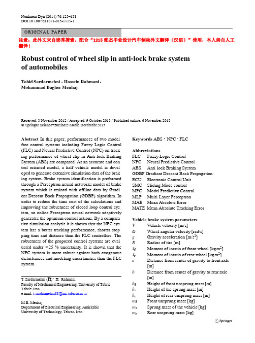
Nonlinear Dyn (2014) 76:125–138DOI10.1007/s11071-013-1115-1翻译!Robustcontrolofwheelslipinanti-lockbrakesystem ofautomobilesTohidSardarmehni·HosseinRahmani·Mohammad BagherMenhajReceived:3November2012/Accepted:9October2013/Publishedonline:6November2013© Springer Science+Business Media Dordrecht2013Abstract In this paper, performances of two model- free control systems including Fuzzy Logic Control (FLC) and Neural Predictive Control (NPC) on track- ing performance of wheel-slip in Anti-lock Braking System (ABS) are compared. As an accurate andcon- trol oriented model, a half vehicle model is devel- opedtogenerateextensivesimulationdataofthebrak- ing system. Brake system identification is preformed through a Perceptron neural networks model of brake system which is trained with offline data by Gradi- ent Descent Back Propagation (GDBP) algorithm. In order to reduce the time cost of the calculations and improving the robustness of closed loop control sys- tem, an online Perceptron neural network adaptively generatestheoptimumcontrolactions.Byacompara- tive simulation analysis it is shown that the NPC sys- tem has a better tracking performance, shorter stop- ping time and distance than the FLC controllers. The robustness of the proposed control systems are eval- uated under ±25 % uncertainty. It is shown that the NPC system is more robust against both exogenous disturbances and modeling uncertainties than theFLC system.T. Sardarmehni(B) ·H.Rahmani FacultyofMechanicalEngineering,UniversityofTabriz, Tabriz,Irane-mail:t.sardarmehni88@ms.tabrizu.ac.irM.B.MenhajDepartment of Electrical Engineering,AmirkabirUniversity of Technology, Tehran,Iran Keywords ABS ·NPC ·FLCAbbreviationsFLC FuzzyLogicControlNPCNeuralPredictiveControlABS Anti-lock BrakingSystemGDBP Gradient Descent Back PropagationECU Electronic ControlUnitSMC SlidingModecontrolMPCModelPredictiveControlMLP Multi-LayerPerceptronMAE MeanAbsoluteErrorMATE Mean Absolute TrackingErrorVehicle brake systemparametersV Vehicle velocity[m/s]ωWheel angular velocity[rad/s]g Gravity acceleration[m/s2]R Radius of tire[m]J f Moment of inertia of front wheel [kgm2]J r Moment of inertia of rear wheel [kgm2]a Distance from center of gravity to frontaxle[m]b Distance from center of gravity to rearaxle[m]h f Height of front unsprung mass[m]h s Height of the sprung mass[m]h r Height of rear unsprung mass[m]m f Front unsprung mass[kg]m s Sprung mass of the vehicle[kg]m r Rear unsprung mass[kg]126T. Sardarmehni etal. Fig. 1 Friction coefficientversus wheel slip[2]m tot Total mass of the vehicle[kg]P i Hydraulic pressure[kPa]P p Constantpumppressure[kPa]P low Constantreservoirpressure[kPa]C d1 BuildvalvecoefficientC d2Dumpvalvecoefficient A wc Wheelcylinderarea[m 2]hMechanicalefficiencyB F Brakefactorr r Effective radius of braking disk[m]C f CoefficientofflowK br Brake displacement proportionalityconstant1 IntroductionReducingrequiredstoppingtimeanddistanceinbrak- inghasalwaysbeenoneofthemostimportantcontrol goalsindesigningthebrakingsystemsofautomobiles. Without any control on angular velocity of wheels,an ordinary braking system exerts dissident fixed brak- ing torque on wheels. This fixed torque causes abrupt decrease in wheel angular velocity with a greater rate than the vehicle speed which results in wheel lock- ups during braking. Through locking-up, friction co- efficient and road adhesion become smaller which re- ducestheactive-appliedbrakingtorqueontires.Asthe result, the stopping time increases and vehicle stops afteralongerdistance.Furthermore,directionalstabil- ity of vehicle would considerably degrade. Toprevent wheel lock-ups and their probable catastrophicconse- quences during severe braking, ABS has been intro- duced to automotive industry. The main idea in ABS is controlling the active brake torque so that prevents wheel lock-ups. This procedure results in generationofmaximumnegativeaccelerationofvehiclewhiletheRobustcontrolofwheelslipinanti-lockbrakesystemofautomobiles 127 directional stability and steering ability of vehicle isguaranteed[1].Inordertogeneratethemaximumnegativeacceler-ation of vehicle, the longitudinal force should bekept around its peak value which requires thefrictionforce to be at its peak amount [2].Researches show that thevalueofthefrictioncoefficientgreatlydependsonroad conditions. As shown in Fig. 1, the peakvalueoffrictioncoefficientvariesfrom0.02to0.43indifferentroad conditions[2].In general, two different strategies are used tocon- trol the braking torque in ABS for preventingwheel lock-ups. The first method is based on wheeldeceler- ation. In this method no information fromvehicle ve-locitysensorsisrequired.However,theoperatingloadfrom the road cannot be used completely in wheelde-celerationmethod.Thesecondmethoduseswheelslipratio, defined by the ratio of the difference betweenwheel linear velocity and vehicle speed over vehiclespeed. The second method uses the oil pressure inanactuatortoregulatethebrakingtorque.Thisregulation ispreformedasthewheelslipratiotracksapredefinedvalue regarding the friction coefficient peak valuein different road conditions [3,4].PI-controllers, which are commonly used in ABSof automobiles, require long time calibrationprocess and would not function effectively in thepresence of exogenous noises and disturbances.Furthermore, the performance of a PI controller isnot satisfactory robust to the vehicle brake modelsevere nonlineari-ties,structuredorunstructureduncertainties,andtime-varying dynamics due to variation of roadandvehicle conditions. Nowadays, regarding theadvancementsin microcomputer industry, theintelligent and adaptive controltechniquescouldbeimplementedinElectronicControl Units (ECU) of vehicles. Besides thesignif-128T. Sardarmehni etal. icant transient and steady-state performances, these controllers are adjusted simply and also are robust to the uncertainties[5].As the state of the art in the designing of ABSs, FLC and neural networks have been used. Regarding satisfactory transient and steady-state performance of the FLC in nonlinear time-varying systems, signifi- cantresearchhasbeenperformedonthesecontrolsys- tems.MauerdesignedaFLCsystemappliedonaquar- ter vehicle model which could identify different road conditions. The proposed FLC system could generate action brake signals through considering current and past values of the brake pressure and slip ratio [6]. Zhang et al. developed a FLC system by considering data to estimate vehicle speed. The estimated vehi- cle speed was used for predicting the amount of slip. Theproposedcontrollercalculatedthemodifiedbrake torque signal based on the predicted the amount of wheelslip[11].Jacquetetal.proposedaMPCsystem togeneratetheoptimalbraketorque.Theonlinerecon- structionwasdonebaseduponestimationofthebrake adhesion torque and estimation of the wheel speed. Furthermore, the necessity of wheel speed sensors for identifying the tire/road characteristics was avoided by using a torque sensor located in the wheel. The simulation results showed that the proposedcontroller had a fast and stable response under rapid changes of theroadconditions.Moreover,thedesignedcontroller dμ dμdλand ( dλ)/dt as inputs of the controller. The pro- posed FLC system led to better performance in pedal pushingfeeling[3].Sharkawydevelopedaself-tuning PID controller which was accompanied by Fuzzy and Geneticalgorithmtoobtaintheoptimalmodulesofthe designed FLC. The results showed that the proposed controller had a fast response with low overshoot and short stopping distance[7].As a model-based nonlinear control system, the Sliding Mode control (SMC) systems are preferred duetotheirfastandtheeaseoftheirapplicationonthenonlinear models. Besides the possibility of fast im- plementation, the robustness and the stability of SMC could be guaranteed in most applications [8]. There has been much research work on application of SMC systems in ABS. Harifi et al. designed a SMC sys- tem for ABS which used integral switching surface for reducing the chattering effects [9]. Half vehicle model was used so the designed controller provided two separated brake torques for front and rear wheel. Furthermore, the results of this controller were com- paredwiththoseofaFuzzy,aselflearningFuzzyslid- ing mode and a neural network hybrid controller. It wasstatedthatthedesignedcontrollerhadtheshortest stoppingdistance.However,theneuralnetworkhybrid controller had the least amount of wheel slip tracking error regarding to other controllers[9].Model Predictive Control (MPC) is a control tech- nique that tries to minimize the tracking errorthrough predictions of the future outputs of a plant which de- finesthepredictionhorizon[10].Duetotherobustand stable performance of this control system, it has al- ways attracted the attention of control engineers. An- war and Ashrafi presented a MPC system for ABS. The presented method required wheel speed sensors could satisfactorily shorten the stopping distance[1]. In this paper, half vehicle model is used for gen- erating the simulation data of a braking system. Two differentmodel-freecontroltechniquesincludingFLC andneuralnetworkMPCsystemsaredeveloped.Fora better assessment, the overall performance of the pro- posed FLC and MPC systems are compared. A neu- ral network-based algorithm is developed in the MPC system to generate the brake torque through track- ing a modified desired slip trajectory. In the MPC system, identification of the half vehicle brake sys- tem model is performed by a Multi-Layer Perceptron (MLP) neural network for the front wheel. In order to improve the identification error and cope with the se- vere time-varying dynamics of the vehicle brake sys- temmodel,asmalldatacollectionsampletimeisused for collecting the training patterns of the neural net- works.Inordertoincreasethecalculationspeedofthe MPC system, the brake system identification is per- formed by an offline MLP model. Training process of the MLP neural network model of the brake sys- tem is performed with offline data by Gradient De- scent Back-Propagation (GDBP) algorithm. In order toacceleratethecomputationsintheMPCsystem,the prediction horizon is shortened. To accelerate the op- timization and improve the robustness of the control system,adaptivestrategyisusedintheoptimizationof the MPC system. In the NPC system, an online MLP neural network is adaptively designed to generate the optimum values of brake torque such that predicted amount of slip in the NPC tracks its modified desired value. Here, GDBP algorithm is used for the online training of the MLP system in the controller. At the end,robustnessofthedesignedFLCandNPCsystems against modeling uncertainties and inputdisturbancesRobustcontrolofwheelslipinanti-lockbrakesystemofautomobiles 129 F = (m h + m h + m h) ⎪⎪ Fig. 2 Free-body diagramof the halfvehiclemodel[12]are evaluated by imposing 25 % Gaussian noises. Be- tweentheproposedmodel-freecontrolsystems,itwas seenthattheNPCsystemismorerobustthantheFLC system.Thesimulationresultsshowedthatthecontrol action input is a smooth signal in the designed NPC. The normal force can be considered as the difference between the vehicle mass distribution and mass trans- fer of the vehicle during acceleration or deceleration. The normal force due to vehicle mass distribution can be formulated as[12] Besides,thestoppingtimeanddistanceisshorterin ⎧ b the NPC system than the FLC controlsystem.The entire program is running in MATLAB/simu- linksoftware.⎪⎨F zf 1=a +b (m tot g) a ⎪⎩F zr 1=a +b (m tot g) (4)2 SystemdynamicsThe second part of the normal force on front wheel is obtainedfromusingtheconversionlawofmomenton rear wheel as[12] 2.1 A half vehicle dynamicmodelComprehensive vehicle models including all parame- ters are not control oriented models due to their com- plexity and highly nonlinearity. Therefore, a simpli- fied dynamical vehicle model that possesses all the (a +b)F zf 2=(m f h f +m s h s +m r h r )V ˙ Dividing both sides to (a + b ), onehas V ˙ zf 2 f f s s r r (a +b) (5) (6) main characteristics of vehicle systems isconsidered.A free-body diagram of the half vehicle model is shown in Fig.2.Applying the same procedure on the front wheels,the normal force of rear tire can be definedas V ˙ As shown in Fig. 2, steering effects and drag force are not considered in modeling to avoid complexity. The total traction force can be presented as[12] F tot = F xf +F xr (1) F zr 2=−(m f h f +m s h s +m r h r )(a +b) The normal forces of tires are defined as[12] ⎧F zf =F zf 1−F zf 2 ⎪⎪ (7) In(1),F xf and F xr are,respectively,thefrontandrear longitudinaltire-roadcontactforcesandaredefined ⎪⎪⎪ ⎨ b = a +b V ˙ m t g −(m f h f +m s h s +m r h r )(a +b) (8) as[12] ⎪⎪F zr =F zr 1−F zr 2 ⎪ F xf =μ(λf )F zf (2) ⎪⎪ a V ⎪⎪ ˙ F xr =μ(λr )F zr (3) where F zf and F zr arethenormalforcesactingonthe frontandrearwheel.μ(λf )and μ(λr )arefrictioncoef- ficientsbetweenroadandfront/reartires,respectively. ⎩ =a +b m t g +(m f h f +m s h s +m r h r )(a +b) Through some substitutions, the total traction force is obtained as[12] F tot =μ(λf )(m 1g −m 3V ˙)+μ(λr )(m 2g +m 3V ˙)(9)130T. Sardarmehni etal. ⎪ ⎩ ⎨ ⎪ 2J f ⎪⎪ ⎪ − Table 1 Constant values for different road condition [2] Road condition C 1 C 2 C 3where ⎧m 1=b m totand F zr in (14) and (15), angular acceleration for front wheel and rear wheel would be definedas 1 ⎪⎪ . . ⎪⎪ ⎨ m 2= ⎪⎪ a +b a a +btot(10)ω˙f =2J 1 −T bf +μ(λf )m 1gR −μ(λf )m 3R V ˙+T e (16) ⎪⎪⎪m 3= m f h f + m s h s +m r h ra +bω˙r = 2J r .T br +μ(λr )m 2gR +μ(λr )m 3R V ˙. (17) In (10), λ is the wheel slip which can be formulated for the front and rear wheel as[12]Since the main goal is controlling the wheel slip, the defined state variables in this paper are vehicle veloc- ity, the front and rear wheel slip (x 1 = V and x 2 =λf ⎧⎪λf = ⎪⎩λr = V −ωf RV V −ωr R V(11)and x 3 = λr ). Consequently, the state-space equations could be defined as[12] ⎧x ˙1=V ˙=f 1(x 2,x 3) ⎪ Wheel slip changes from 0 to 1 which indicatescom- pletelyrollingtireontheroadwithoutanyslipand⎪⎪⎪x ˙2 ⎪ =λ˙f bf wheel lock-up, respectively. Mostly, wheel lock-ups happen during deceleration while the angular veloc- ⎪⎪⎨ ⎪⎪ f 1(x 2,x 3)(1−x 2)−Rf 2(x 2,x 3)+RT = V (18) ity of wheels becomes zero. Burckhardt tire friction model is used to describe the relationship betweenthe ⎪⎪⎪x ˙3=λ˙r ⎪ RT br friction coefficient and wheel slip[2]:⎪⎪⎩ f 1(x 2,x 3)(1−x 3)−Rf 3(x 2,x 3)+ = V 2J r μ(λ) = C 1.1 − e −C 2λ.−C 3λ (12)where C 1, C 2 and C 3 are constants which depend on where ⎧ ⎪⎪f 1(x 2,x 3)=−g μ(x 2)m 1 +μ(x 3)m 2 roadcondition.Table 1showsthedifferentvaluefor ⎪⎪⎪ m tot 1 −μ(x 2)m 3 +μ(x 3)m 3 various roadconditions.By assuming the front wheel to be the driver one, the engine torque only acts on the front wheel. Free- body diagram of the Front-wheel is shown in Fig. 3. Applying Newton’s second law along the horizontal ⎨f 2(x 2,x 3)= ⎪⎪⎪ ⎪⎩f 3(x 2,x 3)= 2J f 1 2J r .μ(x 2)m 1Rg − μ(x 2)m 3Rf 1.(19) .μ(x 3)m 2Rg −μ(x 3)m 3Rf 1. direction one has[12]m tot V ˙=−F tot (13) 2J f ω˙f =−T bf +μ(λf )F zf R +T e (14) 2J r ω˙r =−T br +μ(λr )F zr R (15) In(14),T e representstheenginetorquewhichwould becomezeroduringdeceleration.Bysubstituting F zf 2.2 Dynamics of the hydraulic brakemodelThe structure of a standard hydraulic brake actuatoris shown in Fig. 4. There are two solenoid valves which can only be open or close. The amount of braking pressure is regulated through the opening conditionof each valve which is simply specified by coefficients C d1 and C d2. For instance, when C d1 = 1 and C d2 =0 f Dryasphalt 1.2801 23.99 0.52 Drycobblestones 1.3713 6.4565 0.6691 Dryconcrete 1.1973 25.168 0.5373 Wetasphalt 0.857 33.822 0.347 Wet cobblestones 0.4004 33.708 0.1204 Snow 0.1946 94.129 0.0646 Ice 0.05 306.39 0 Fig. 3 Front-wheel free-body diagram[12]Robustcontrolofwheelslipinanti-lockbrakesystemofautomobiles 131− = − Fig. 4 Structure of astandard hydraulicmodel[13]Fig. 5a Membershipfunction ofvelocitythe build valve is open and the dump valve is closed (see Fig. 4) which increases the braking pressure and vice versa. The hydraulic system dynamic model can be represented as[13]in this section. The parallel structure of FLC systems enables the control system to activate all rules simul- taneously. This characteristic of the FLC systems im- proves the required time for calculations[6]. In general, FLC systems perform four mainstages C dp i f dt ,2 = A 1C d1 ρ (P p −P i ) which are Fuzzification, rule base, inference mecha- nism and Defuzzification. Fuzzification andDefuzzi- −A 2C d2 ,2 (P i P low ) (20) ρ ficationstagestransformanynumericaldatatoitscor- responding fuzzy value and vice versa. The inferencemechanismdeterminesthematchingdegreeofthecur- Throughsomesimplifications,thebraketorquecanbe defined as[13] T b =P i A wc ηB F r r (21) It is assumed that the brake torque defined by (21), only acts on the driver wheel which is the front one. Theamountoftherearwheelbraketorqueisdepended on that of the front wheel and could be definedas T br =K br T bf (22) The value for K br is often selected to be less than 1 in order to prevent rear wheel lock-ups at the situations which front wheel locks-up[12]. 3 An ABS fuzzy controllerdesign Due to an acceptable performance of the FLC in non- linearsystems,thistypeofcontrolsystemisdevelopedrent fuzzy input with respect to each rule and decides which rules should be fired. At the end, the firedrules are combined to form the control action[14].Mamdani method is applied for designing a fuzzy controller for the front wheel. The input vector of the proposed controller is consisted of the vehicle speed, wheel slip error and oil pressure differences. The wheel slip error is the difference between the current wheel slip and the modified desired wheel slip which varies with the condition of the road. The wheel-slip errors of the front and rear wheel are definedas .e f λd λf (23) e r = λd −λrAs shown in Figs. 5a , 5b , 5c and 5d , six Gaussian membership functions are used for the vehicle speed. Moreover, seven Gaussian membership functions are usedforthewheelsliperror;fortheoilpressurediffer-encetwoS-shapemembershipfunctionsareused.De-130 T. Sardarmehni etal. Fig. 5b Membershipfunction of LambdaerrorFig. 5c Membershipfunction ofΔPFig. 5d Membershipfunction of C dTable 2a Positive pressure difference (ΔP >0) Table 2b Negative pressure difference (ΔP <0)Vλerror VλerrorNVB NB NS ZO PS PB PVB NVB NB NS ZO PS PB PVBVS DEC DEC DEC DEC INC INC INC VS DEC DEC DEC DEC INC INC INC S DEC DEC DEC DEC INC INC INC S DEC DEC DEC DEC INC INC INC M DEC DEC DEC DEC INC INC INC M DEC DEC DEC DEC INC INC INC B DEC DEC DEC DEC INC INC INC B DEC DEC DEC INC INC INC INC VB DEC DEC DEC DEC INC INC INC VB DEC DEC DEC INC INC INC INC VVB DEC DEC DEC DEC INC INC INC VVB DEC DEC DEC INC INC INC INCfuzzification is performed through two Z-shapemem- bershipfunctions.After defining fuzzy sets for inputs and output, fuzzy control rules are designed as described in Ta- bles2a and 2b. Fuzzy control rules are developed for two different positive and negative oil pressurediffer- ence situations. In Tables 2a and 2b, INC represents the command that opens the build valve and closes the dump valve and DEC expresses the commandthat closesthebuildvalveandopensthedumpvalve. 4MultiLayerPerceptron(MLP)modelingofthe brakesystem4.1Structure of the MLP neuralnetworkThe structure of a MLP neural network is shown in Fig. 6. The proposed neural network model of the brake system is consisted of two layers comprising hidden layer and output layer. The input data are re-ceivedanddistributedtothenodesofthehiddenlayer.132T. Sardarmehni etal. 2 2 × f W (i,1) W 1 W (j,1) Fig. 6 Block diagram ofMLP neuralnetworksThe nonlinear activation function, f 1 in everyneuronofthehiddenlayerreceivestheweightedsumofallin-putdataplusthebiastermofeachcorrespondingnode.Intheoutputlayer,theweightedoutputsofthehidden layerarelinearlysummeduptotheoutputlayer’sbiaswhere Q is the total number of training patterns and l defines the in-process training pattern. Based on the back propagation algorithm, the bias term of (27) is updatedas ∂E(k) term and form the output of thenetwork.b 2(k +1)=b 2(k)−η ∂b 2(30) Assuming the number of inputs as p , the numberof neurons in the hidden layer as q and the dimen-sion of the network’s output as 1, the attributes ofthewhere η is a small positive number called thelearning rate. More precisely, it can beshown Q neural network model become as W 1 R q ×p ,b 1R q ×1,2 2 .∂E(k) ∂y(l) net 1 R q ×1, a 1 R q ×1, W 2 R q ×1 and b 2 R 1×1.Theactivationfunction f 1isasigmoidfunctiondefinedas 2b (k + 1) = b (k) −η = b (k) −η l =1 Q . ∂y(l)∂b 2(k) e l (l) (31) f 1(x)=1 +exp (−βx) − 1 (24)l =1 The same procedure can be performed for updating where 0 < β <1 is a tuning parameter and could beadjusted by experience or trial and error. Now, theweightedinputvector,P isgatheredwiththeneuron’sW 1, W 2, and b 1. So onehas W 2(k +1) Q bias term to obtain net 1as= W (k) −η .∂E(k) ∂y(l) 2 net 1 = W 1P +b 1 (25)l =1 Q ∂y(l) ∂W (k) Therefore, the output of the hidden layer, a 1 isob-2 . 1. 1 1. tainedasa 1 =f .net 1. (26)= b (k) −η b 1 l =1 e l (l)f W P (l) +b (32)The network’s overall output can now be obtained asfollows [10, 15,16]:(i,1)(k +1) =b 1 Q ..l (1,i) y = W 2a 1 +b 2 (27)(i,1)(k) −η l =1 e (l) ×W 2 (k) r .1 (i,j) (k)P (i,1)(l)+b 1 (k).. (33) 4.2 Training algorithm of the MLPnetworkThe parameters of MLP model, including b 1, b 2,W 1And similarly, onehas (j,i)(k +1) Q . and W 2,areupdatedbytheGDBPalgorithmbasedonthefollowingerror,e l :e l = y −y d (28)= W 1 (k) (j,i) .p −η.e l (l)W 2f r j l =1 .where y and y d are the MLP’s and desired outputs,respectively.Theindexofperformancecanbedefined..1 × (j,i) i =1 . (k)P (i,1)(l)+b 1 (k). as×P (j,1)(l) 1 Q (34) .. .E =2l =1y(l)−y d (l) (29)Comprehensive details and formulation of GDBP al- gorithm can be found in [10, 15,16].Robustcontrolofwheelslipinanti-lockbrakesystemofautomobiles133Fig. 7a Illustration ofnormalized brake torqueused fortrainingFig. 7b Illustration ofnormalized slip ratio usedfortraining4.3 The MLP model training and validationdataFor the front wheel, an MLP neural network istrainedby the GDBP algorithm. Considering λ(t) as the out-put slip of each MLP network at the current sampletime, t , the input vector of the training process is con-sistedofthebraketorqueandtheslipat(t −1)and(t ) as P = .T b (t), T b (t − 1), λ(t − 1), λ(t −2).T (35)ThroughwidespreadsimulationdataoftheMLPbrakesystem model, four neurons are chosen in the hid-den layer and thereby the neural network parame-ters are specified as W 1 R 4×4, b 1 R 4×1, W 2 R 4×1and b 2 R 1×1. A 4000-tuple random signal of braketorque, which was bounded to the interval 400 to5000 (Newton-meter), is imposed to the brakesystemmodel. To consider both the transient and the steady-state performance of the brake system, one half ofthe training patterns are generated with pulse widthof0.1 second and the other half has a wide pulse width,1.5 second. By imposing the input training data onthe brake system, 4000 output values for slip are gen-erated, which are used in the training process of the neural network systems. As Figs. 7a and 7b show, all trainingpatternsarenormalizedintotheinterval [0,1]. A fixed 0.01 second sample time is used in the gener- ation of the training data. β in (24) is considered2. In training with GDBP, the learning rate is set to 0.001. The initial values for weights and biases were taken as random numbers. The training process was finished when all errors (29) of the training patterns reached 0.01. The training process with GDBP was performedin458.25seconds.Aftertraining,theaccu- racy of the trained MLP model is evaluated by a new set of bounded random samples for the brake torque. Theresulted0.0026MeanAbsoluteError(MAE)cor- responding to the evaluation data in Fig. 8is signifi- cantlysmall. TheconvergedweightandbiasesoftheMLPneural network models for the front wheel are presented in Table 3. 5 MPC The schematic of the proposed NPC system is shownin Fig. 9. In each sample time, the NPC generates N u134T. Sardarmehni etal.⎢ ⎢ ⎢ ⎥⎥Fig. 8 Illustration ofvalidationdataMAE =0.0026Fig. 9 Schematic of NPCsystemTable 3 Final parameters of the MLPmodel⎡0.1791 ⎤ T ⎡0.4025 ⎤ ⎡ 0.2504 −0.1039 0.08790.4792 ⎤ ⎢0.6155 ⎥⎢0.6992 ⎥ ⎢ 0.1193 −0.1287 0.74980.4613 ⎥ b 1=⎢− ⎥ b 2 =−0.0847 W 2 =⎢ ⎥ W 1 =⎢ ⎥ 0.4755 ⎥ −0.2207⎥ ⎢0.6112 0.5432 0.7971 0.5464⎥ ⎣ ⎦1.1208 ⎣ ⎦ 0.6099 ⎣ ⎦ 0.4545 0.3086 0.8599 0.8654number of future constrained control inputs such thatthe predicted amount of system output tracks a modi-fied desired trajectory throughout the prediction hori-zon. N u defines the predictionhorizon.InFig.9,T b (t 0)and λ(t 0)showthebraketorqueand the slip at time t 0, respectively. Therefore, in thetime interval t 0 through t 0+Δt , all the components ofthe following vector, P i are known for i =0: P i =.T b (t 0 +iΔt),T b .t 0 +(i −1)Δt .,λ.t 0+(i −1)Δt .,λ.t 0+(i −2)Δt ..Ti =0,..., N u (36)In the NPC system, the vector P i is given to the MLPmodel of the brake system for predicting the slip.Therefore,intheinterval,t 0to t 0+Δt ,NPCrequiresthe predicted values of T b and λ at time samples t 0 + iΔt (i = 0,..., N u ). The values of λ(t 0 + iΔt) for each P i in Fig. 9is predicted through the trained MLP model of the brake system using P i −1 for i = 1,..., N u . The optimal values of T b (t 0 + iΔt) are obtained through the optimization process fully discussed in Sect.5.1. Theonlineoptimizationresultsinoptimizedvalues of all U i s in each sample time. As shown in Fig. 9, only the first component of P 1, which is shown as U 1,is used as the control input. Similarly, the remain- ing U i s are considered as the initial values for the fu- ture time steps, recursively. This usage of the preced- ing optimized values as the initial values of the cur- renttime results in fast convergence of the NPC sys- tem.Robustcontrolofwheelslipinanti-lockbrakesystemofautomobiles135 2 = − (j,1) = − + = − = − 1 + = 1 − 1 W W ∂Ψ (k) 2 W (j,1) (i,1) . f 5.1 OptimizationForreducingthecalculation’stimecostandimproving therobustnessoftheMPCsystem,optimizationunitis constructedbasedonMLPneuralnetworks.Inthepro- and ∂U 1(k) ∂Φ2(k) =1 (44) Similarly, ψ 2 is updatedas posedoptimizationmethod,anMLPneuralnetworkis adaptivelytrainedtogeneratetheonlineoptimumval- ues for control actions. These optimal control actions aregeneratedbasedonthetrackingperformanceofthe slip in the MPCsystem.As a result, an MLP neural network with thesame Ψ2(k +1)=Ψ2(k)−η∂E(k) ∂Ψ(k) From chain rule, (45) simplifiesto Ψ 2(k +1) Ψ 2(k) η∂E(k) ∂e l (k) ∂λ1(k)∂U 1(k) ∂e l (k) ∂λ1(k) ∂U 1(k) ∂Ψ2(k) (45) (46) structuregiveninSect.4.1isusedforanonlinegener- ation of front wheel brake torque signal. Considering ψ 1 and ψ2 as the first and second layer weightmatri- ces, and ϕ1 and ϕ2 as the first and second layer bias terms, the output can be definedaswhere: ∂U 1(k) ∂Ψ2(k) 4 ..4 .. U 1=Ψ2g .Ψ1X 0+Φ1.+Φ2 (37) = g i =1 . j =1 1 (i,j) X 0(j,1)+Φ1 (47) where g is the activation function defined by (24) for β = 2. For N u = 1, the error terms can be definedas According the GDBP algorithm, Φ1 could be updated as 1 1 ∂E(k) e l = λ(1)−λd (1) (38) where λ(1) is definedasλ(1) = W 2f 1.W 1X 1 + b 1.+b 2 (39)Φ (k + 1) = Φ (k)−η∂Φ1(k) (48) We apply the chain rule andwrite Φ1(k +1) The error term is definedas Φ1(k) η∂E(k) ∂e l (k) ∂λ1(k)∂U 1(k) ∂e l (k)∂λ1(k)∂U 1(k)∂Φ1(k) (49) 1 2with E = 2e l (40) ForonlineupdatingoftheparametersoftheMLPnet- work, back propagation algorithm is used. Hence,one ∂U 1(k) ∂Φ1(k) 4 . .4 .. has = .Ψ 2 r .(i,j)X 0(j,1)+Φ(j,1) Φ2(k 1) Φ2(k) η∂E(k)∂Φ2(k)(41)i =1 (i,1)g Ψ1 j =1 1 (50) We use the chain rule to rewrite (40)as Φ2(k +1) Φ2(k) η∂E(k) ∂e l (k) ∂λ1(k)∂U 1(k)∂e l (k)∂λ1(k)∂U 1(k)∂Φ2(k)(42)By the same procedure ψ1 can be updatedas ∂E(k) Ψ (k 1) Ψ (k) η ∂Ψ1(k) We use the chain rule toobtain Ψ 1(k +1) (51) The first two partial derivative terms on the rightside of(42)areeasilydefinedandthethirdtermcanbe =Ψ1(k)−η∂E(k)∂e l (k)∂λ1(k)∂U 1(k) (52) formulatedas4 .where ∂e l (k) ∂λ1(k) ∂U 1(k)∂Ψ (k) ∂λ1(k) ∂U 1(k)= .i =1 2 (1,i) 1 r(i,1) ∂U 1(k ) 1 (i,j) = Ψ (i,1)X 0(i,1)g r .4. × j =11 (i,j) ..X 1(j,1)+b 1 (43).4 . × j =1 1 (i,j) . X 0(j,1)+Φ1 (53) Ψ Ψ。
汽车制动系统-毕业设计外文资料翻译

Automobile Brake SystemThe braking system is the most important system in cars. If the brakes fail, the result can be disastrous. Brakes are actually energy conversion devices, which convert the kinetic energy (momentum) of the vehicle into thermal energy (heat).When stepping on the brakes, the driver commands a stopping force ten times as powerful as the force that puts the car in motion. The braking system can exert thousands of pounds of pressure on each of the four brakes.Two complete independent braking systems are used on the car. They are the service brake and the parking brake.The service brake acts to slow, stop, or hold the vehicle during normal driving. They are foot-operated by the driver depressing and releasing the brake pedal. The primary purpose of the parking brake is to hold the vehicle stationary while it is unattended. The parking brake is mechanically operated by when a separate parking brake foot pedal or hand lever is set.The brake system is composed of the following basic c omponents: the “master cylinder” which is located under the hood, and is directly connected to the brake pedal, converts driver foot’s mechanical pressure into hydraulic pressure. Steel “brake lines” and flexible “brake hoses” connect the master cylinder to the “slave cylinders” located at each wheel. Brake fluid, specially designed to work in extreme conditions, fills the system. “Shoes” and “pads” are pushed by the slave cylinders to contact the “drums” and “rotors” thus causing drag, which (hopefully) slows the car.The typical brake system consists of disk brakes in front and either disk or drum brakes in the rear connected by a system of tubes and hoses that link the brake at each wheel to the master cylinder (Figure).Basically, all car brakes are friction brakes. When the driver applies the brake, the control device forces brake shoes, or pads, against the rotating brake drum or disks at wheel. Friction between the shoes or pads and the drums or disks then slows or stops the wheel so that the car is braked.In most modern brake systems (see Figure 15.1), there is a fluid-filled cylinder, called master cylinder, which contains two separate sections, there is a piston in each section and both pistons are connected to a brake pedal in the driver’s compartment. When the brake is pushed down, brake fluid is sent from the master cylinder to the wheels.At the wheels, the fluid pushes shoes, or pads, against revolving drums or disks. The friction between the stationary shoes, or pads, and the revolving drums or disks slows and stops them. This slows or stops the revolving wheels, which, in turn, slow or stop the car.The brake fluid reservoir is on top of the master cylinder. Most cars today have a transparent reservoir so that you can see the level without opening the cover. The brake fluid level will drop slightly as the brake pads wear. This is a normal condition and no cause for concern. If the level drops noticeably over ashort period of time or goes down to about two thirds full, have your brakes checked as soon as possible. Keep the reservoir covered except for the amount of time you need to fill it and never leave a cam of brake fluid uncovered. Brake fluid must maintain a very high boiling point. Exposure to air will cause the fluid to absorb moisture which will lower that boiling point.The brake fluid travels from the master cylinder to the wheels through a series of steel tubes and reinforced rubber hoses. Rubber hoses are only used in places that require flexibility, such as at the front wheels, which move up and down as well as steer. The rest of the system uses non-corrosive seamless steel tubing with special fittings at all attachment points. If a steel line requires a repair, thebest procedure is to replace the compete line. If this is not practical, a line can be repaired using special splice fittings that are made for brake system repair. You must never use copper tubing to repair a brake system. They are dangerous and illegal.Drum brakes, it consists of the brake drum, an expander, pull back springs, a stationary back plate, two shoes with friction linings, and anchor pins. The stationary back plate is secured to the flange of the axle housing or to the steering knuckle. The brake drum is mounted on the wheel hub. There is a clearance between the inner surface of the drum and the shoe lining. To apply brakes, the driver pushes pedal, the expander expands the shoes and presses them to the drum. Friction between the brake drum and the friction linings brakes the wheels and the vehicle stops. To release brakes, the driver release the pedal, the pull back spring retracts the shoes thus permitting free rotation of the wheels.Disk brakes, it has a metal disk instead of a drum. A flat shoe, or disk-brake pad, is located on each side of the disk. The shoes squeeze the rotatin g disk to stop the car. Fluid from the master cylinder forces the pistons to move in, toward the disk. This action pushes the friction pads tightly against the disk. The friction between the shoes and disk slows and stops it. This provides the braking action. Pistons are made of either plastic or metal. There are three general types of disk brakes. They are the floating-caliper type, the fixed-caliper type, and thesliding-caliper type. Floating-caliper and sliding-caliper disk brakes use a single piston. Fixed-caliper disk brakes have either two or four pistons.The brake system assemblies are actuated by mechanical, hydraulic or pneumatic devices. The mechanical leverage is used in the parking brakes fitted in all automobile. When the brake pedal is depressed, the rod pushes the piston of brake master cylinder which presses the fluid. The fluid flows through the pipelines to the power brake unit and then to the wheel cylinder. The fluidpressure expands the cylinder pistons thus pressing the shoes to the drum or disk. If the pedal is released, the piston returns to the initialposition, the pull back springs retract the shoes, the fluid is forced back to the master cylinder and braking ceases.The primary purpose of the parking brake is to hold the vehicle stationary while it is unattended. The parking brake is mechanically operated by the driver when a separate parking braking hand lever is set. The hand brake is normally used when the car has already stopped. A lever is pulled and the rear brakes are approached and locked in the “on” position. The car may now be left without fear of its rolling away. When the driver wants to move the car again, he must press a button before the lever can be released. The hand brake must also be able to stop the car in the event of the foot brake failing. For this reason, it is separate from the foot brake uses cable or rods instead of the hydraulic system.Anti-lock Brake SystemAnti-lock brake systems make braking safer and more convenient, Anti-lock brake systems modulate brake system hydraulic pressure to prevent the brakes from locking and the tires from skidding on slippery pavement or during a panic stop.Anti-lock brake systems have been used on aircraft for years, and some domestic car were offered with an early form of anti-lock braking in late 1990’s. Recently, several automakers have introduced more sophisticated anti-lock system. Investigations in Europe, where anti-lock brakin g systems have been available for a decade, have led one manufacture to state that the number of traffic accidents could be reduced by seven and a half percent if all cars had anti-lock brakes. So some sources predict that all cars will offer anti-lock brakes to improve the safety of the car.Anti-lock systems modulate brake application force several times per second to hold the tires at a controlled amount of slip; all systems accomplish this in basically the same way. One or more speed sensors generate alternating current signal whose frequency increases with the wheel rotational speed. An electronic control unit continuously monitors these signals and if the frequency of a signal drops too rapidly indicating that a wheel is about to lock, the control unit instructs a modulating device to reduce hydraulic pressure to the brake at the affected wheel. When sensor signals indicate the wheel is again rotating normally, the control unit allows increased hydraulic pressure to the brake. This release-apply cycle occurs several time per second to “pump” the brakes like a driver might but at a much faster rate.In addition to their basic operation, anti-lock systems have two other things in common. First, they do not operate until the brakes are applied with enough force to lock or nearly lock a wheel. At all other times, the system stands ready to function but does not interfere with normal braking. Second, if the anti-lock system fail in any way, the brakes continue to operate without anti-lock capability. A warning light on the instrument panel alerts the driver when a problem exists in the anti-lock system.The current Bosch component Anti-lock Braking System (ABSⅡ), is a second generation design wildly used by European automakers such as BWM, Mercedes-Benz and Porsche. ABSⅡ system consists of : four wheel speed sensor, electronic control unit and modulator assembly.A speed sensor is fitted at each wheel sends signals about wheel rotation to control unit. Each speed sensor consists of a sensor unit and a gear wheel. The front sensor mounts to the steering knuckle and its gear wheel is pressed onto the stub axle that rotates with the wheel. The rear sensor mounts the rear suspension member and its gear wheel is pressed onto the axle. The sensor itself is awinding with a magnetic core. The core creates a magnetic field around the winding, and as the teeth of the gear wheel move through this field, an alternating current is induced inthe winding. The control unit monitors the rate o change in this frequency to determine impending brake lockup.The control unit’s function can be divided into three parts: signal processing, logic and safety circuitry. The signal processing section is the converter that receives the alternating current signals form the speed sensors and converts them into digital form for the logic section. The logic section then analyzes the digitized signals to calculate any brake pressure changes needed. If impending lockup is sensed, the logic section sends commands to the modulator assembly.Modulator assemblyThe hydraulic modulator assembly regulates pressure to the wheel brakes when it receives commands from the control utuit. The modulator assembly can maintain or reduce pressure over the level it receives from the master cylinder, it also can never apply the brakes by itself. The modulator assembly consists of threehigh-speed electric solenoid valves, two fluid reservoirs and a turn delivery pump equipped with inlet and outlet check valves. The modulator electrical connector and controlling relays are concealed under a plastic cover of the assembly.Each front wheel is served by electric solenoid valve modulated independently by the control unit. The rear brakes are served by a single solenoid valve and modulated together using the select-low principle. During anti-braking system operation, the control unit cycles the solenoid valves to either hold or release pressure the brake lines. When pressure is released from the brake lines during anti-braking operation, it is routed to a fluid reservoir. There is one reservoir for the front brake circuit. The reservoirs are low-pressure accumulators that storefluid under slight spring pressure until the return delivery pump can return the fluid through the brake lines to the master cylinder.汽车制动系统制动系统是汽车上最重要的系统。
汽车制动器毕业设计外文翻译

TransmissionBrakesBrake is a movement of vehicles or impede the movement of the trend components. According to brake torque generated in different ways, the brakes can be divided into: friction brake and retarder brakes, brake, broadly speaking, usually referred to the friction brake. At present all kinds of cars used by the brake drum brakes and can be divided into two major categories of disc brakes. Drum brake friction in the rotating components of the brake drum, and its work surface for the cylindrical surface of the rotating disc brake components for the brake disc, to end the work surface. In addition, under the rotating components of the installation of different positions, the brakes can be divided into the wheel brakes and brake two categories. Among them, the rotating wheels, brake components installed in thesolid-wheel or axle, brake torque that is a direct role in both sides of the wheels, respectively, for its general travel brake, and can also be used to brake the second and the car braking; rotating components of the brake-installed in the transmission of the transmission shaft, after its brake torque to be driven to the redistribution of the bridge on both sides of the wheel, generally used only for its cars in the system Retarded and dynamic braking.Drum brakes are within and outside the beam-type-two. The former brake drum to work within the cylindrical surface of the car on the wide application of the latter brake drum is the work of Outer cylindrical surface, only a handful of cars will be used in car brakes.Zhang-drum brakes, mainly by the brake drum (Xingzhuang Si pot, installed in the wheel, and synchronization with the rotating wheels), brake shoes, (arc-shaped parts, a group of two, shoes, with a lateral Nien Moment of friction brake lining film), fixed sales andbrake-cylinder, and so on. Brake, brake drum in the internal brake shoes, brake points from one end to bear the Prokinetic cylinder, around the other side of the fulcrum of its outward rotation, the pressure on the brake drum with a round face, then friction Torque.Disc brake mainly by the brake discand calipers. Among them, ventilated brake disc-andtwo-solid; mainly floating calipers clamp, fork-floating, such as several fixed-clamp. Braking system of new technologiesAs people of vehicle safety requirements and the continuous improvement of the rapid development of electronic technology, today's automobile braking system have taken place in the revolutionary progress. On the one hand, the brake system through a variety of sensors for real-time monitoring of the braking system braking to provide a more efficient and effective security assurances on the other hand, automobile braking systems and other systems constitute stretches of the regional network, in Implementation of intelligent brake control at the same time, but also further reduce the energy consumption of motor vehicles; addition, with new materials and new structure of the large number of applications, the reliability of its braking system has been further improved.制动器是产生阻碍车辆运动或运动趋势的力的部件。
汽车制动器毕业设计外文翻译
TransmissionBrakesBrake is a movement of vehicles or impede the movement of the trend components. According to brake torque generated in different ways, the brakes can be divided into: friction brake and retarder brakes, brake, broadly speaking, usually referred to the friction brake. At present all kinds of cars used by the brake drum brakes and can be divided into two major categories of disc brakes. Drum brake friction in the rotating components of the brake drum, and its work surface for the cylindrical surface of the rotating disc brake components for the brake disc, to end the work surface. In addition, under the rotating components of the installation of different positions, the brakes can be divided into the wheel brakes and brake two categories. Among them, the rotating wheels, brake components installed in thesolid-wheel or axle, brake torque that is a direct role in both sides of the wheels, respectively, for its general travel brake, and can also be used to brake the second and the car braking; rotating components of the brake-installed in the transmission of the transmission shaft, after its brake torque to be driven to the redistribution of the bridge on both sides of the wheel, generally used only for its cars in the system Retarded and dynamic braking.Drum brakes are within and outside the beam-type-two. The former brake drum to work within the cylindrical surface of the car on the wide application of the latter brake drum is the work of Outer cylindrical surface, only a handful of cars will be used in car brakes.Zhang-drum brakes, mainly by the brake drum (Xingzhuang Si pot, installed in the wheel, and synchronization with the rotating wheels), brake shoes, (arc-shaped parts, a group of two, shoes, with a lateral Nien Moment of friction brake lining film), fixed sales andbrake-cylinder, and so on. Brake, brake drum in the internal brake shoes, brake points from one end to bear the Prokinetic cylinder, around the other side of the fulcrum of its outward rotation, the pressure on the brake drum with a round face, then friction Torque.Disc brake mainly by the brake discand calipers. Among them, ventilated brake disc-andtwo-solid; mainly floating calipers clamp, fork-floating, such as several fixed-clamp. Braking system of new technologiesAs people of vehicle safety requirements and the continuous improvement of the rapid development of electronic technology, today's automobile braking system have taken place in the revolutionary progress. On the one hand, the brake system through a variety of sensors for real-time monitoring of the braking system braking to provide a more efficient and effective security assurances on the other hand, automobile braking systems and other systems constitute stretches of the regional network, in Implementation of intelligent brake control at the same time, but also further reduce the energy consumption of motor vehicles; addition, with new materials and new structure of the large number of applications, the reliability of its braking system has been further improved.制动器是产生阻碍车辆运动或运动趋势的力的部件。
(机械类)毕业设计说明书附英文翻译-盘式-鼓式制动器测绘与三维实体造型及动画设计
汽车制动系统(鼓,片式)测绘与三维实体造型及动画设计摘要:制动系统作用:使行驶中的汽车按照驾驶员的要求进行强制减速甚至停车;使已停驶的汽车在各种道路条件下(包括在坡道上)稳定驻车;使下坡行驶的汽车速度保持稳定,是汽车中必不可少的组成之一。
本次设计的主要工作包括:对盘式、鼓式制动系统实物进行测绘,基于Solidworks三维参数化建模得到三维模型,对制动系统进行系统动画设计,仿真其工作原理,并基于solidworks motion进行运动分析,更加直观地了解其构造与工作状态。
关键字:盘式;鼓式;动画设计;运动分析;工作原理Automotive brake system (drum, chip) mapping and three-dimensional solid modeling and animation designABSTRACT:the mandatory requirements of the driver slow down or even stop; to have been suspended in the vehicle in various road conditions (including the ramp) stable parking; the downhill speed of cars Stable, is one of the car integral. The design of the main tasks include: disc, drum brake system physical mapping, three-dimensional parameters based on modeling solidworks be three-dimensional model of the brake system of the animation system design, simulation and its working principle, and based on solidworks motion For motion analysis, more intuitive understanding of its structure and working condition.KEY WORDS: disc; drum; animation design; motion analysis; work目录1 前言 (3)1.1 本次毕业设计课题的目的、意义 (3)1.2 完成过程 (4)2 制动器概况 (5)2.1汽车制动器概述 (5)2.2 汽车制动器的优越性 (6)3 盘式基本组成和工作原理 (7)3.1基本组成 (8)3.2基本原理 (12)3.3基本原理和优缺点 (15)4 鼓式基本组成和工作原理 (17)4.1基本组成 (17)4.2基本原理 (21)4.3 驻车制动 (22)5 图片附录 (24)6 参考文献 (35)7 致谢 (36)8 外文翻译 (37)1 前言1.1 本次毕业设计课题的目的、意义毕业设计是培养学生综合运用本学科的基本理论、专业知识和基本技能,提高分析与解决实际问题的能力,完成工程师的基本训练和初步培养从事科学研究工作的重要环节。
制动器外文翻译__曹鹏程
太原理工大学机械工程学院毕业设计外文翻译学生姓名:曹鹏程专业班级:车辆工程1001 指导教师:朱建军THE BRAKE BIBLEThe simple answer: they slow you down.The complex answer: brakes are designed to slow down your vehicle but probably not by the means that you think. The common misconception is that brakes squeeze against a drum or disc, and the pressure of the squeezing action is what slows you down. This in fact is only part of the equation. Brakes are essentially a mechanism to change energy types. When you're travelling at speed, your vehicle has kinetic energy. When you apply the brakes, the pads or shoes that press against the brake drum or rotor convert that energy into thermal energy via friction. The cooling of the brakes dissipates the heat and the vehicle slows down. It's the First Law of Thermodynamics, sometimes known as the law of conservation of energy. This states that energy cannot be created nor destro yed, it can only be converted from one form to another. In the case of brakes, it is converted from kinetic energy to thermal energy.Angular force. Because of the configuration of the brake pads and rotor in a disc brake, the location of the point of contact where the friction is generated also provides a mechanical moment to resist the turning motion of the rotor.If you ride a motorbike or drive a race car, you're probably familiar with the term brake fade, used to describe what happens to brakes when they get too hot. A good example is comi ng down a mountain pass using your brakes rather than your engine to slow you down. As you start to come down the pass, the brakes on your vehicle heat up, slowing you down. But if you keep using them, the rotors or drums stay hot and get no chance to cool off. At some point they can't absorb any more heat so the brake pads heat up instead. In every brake pad there is the friction material that is held together with some sort of resin and once this starts to get too hot, the resin starts to vapourise, forming a gas. Because the gas can't stay between the pad and the rotor, it forms a thin layer between the two whilst trying to escape. The pads lose contact with the rotor, reducing the amount of friction and voila. Complete brake fade.The typical remedy for this would be to get the vehicle to a stop and wait for a few minutes. As the brake components cool down, their ability to absorb heat returns and the next time you use the brakes, they seem to work just fine. This type of brake fade was more common in older vehicles. Newer vehicles tend to have less outgassing from the brake pad compounds but they still suffer brake fade. So why? It's still to do with the pads getting too hot. With newer brake pad compounds, the pads transfer heat into the calipers once the rotors are too hot, and the brake fluid starts to boil forming bubbles in it. Because air is compressible (brake fluid isn't) when you step on the brakes, the air bubbles compress instead of the fluid transferring the motion to the brake calipers. Voila. Modern brake fade.So how do the engineers design brakes to reduce or eliminate brake fade? For older vehicles, you give that vapourised gas somewhere to go. For newer vehicles, you find some way to cool the rotors off more effectively. Either way you en d up with cross-drilled or grooved brake rotors. While grooving the surface may reduce the specific heat capacity of the rotor, its effect is negligible in the grand scheme of things. However, under heavy braking once everything is hot and the resin is vapourising, the grooves give the gas somewhere to go, so the pad can continue to contact the rotor, allowing you to stop.The whole understanding of the conversion of energy is critical in understanding how and why brakes do what they do, and why they are designed the way they are. If you've ever watched Formula 1 racing, you'll see the front wheels have huge scoopsinside the wheel pointing to the front (see the picture above). This is to duct air to the brake components to help them cool off because in F1 racing, the brakes are used viciously every few seconds and spend a lot of their time trying to stay hot. Without some form of cooling assistance, the brakes would be fine for the first few corners but then would fade and become near useless by half way around the track.Rotor technology.If a brake rotor was a single cast chunk of steel, it would have terrible heat dissipation properties and leave nowhere for the vapourised gas to go. Because of this, brake rotors are typically modified with all manner of extra design features to help them cool down as quickly as possible as well as dissapate any gas from between the pads and rotors. The diagram here shows some examples of rotor types with the various modification that can be done to them to help them create more friction, disperse more heat more quickly, and ventilate gas. From left to right.1: Basic brake rotor. 2: Grooved rotor - the grooves give more bite and thus more friction as they pass between the brake pads They also allow gas to vent from between the pads and the rotor. 3: Grooved, drilled rotor - the drilled holes again give more bite, but also allow air currents (eddies) to blow through the brake disc to assist cooling and ventilating gas. 4: Dual ventilated rotors - same as before but now with two rotors instead of one, and with vanes in between them to generate a vortex which will cool the rotors even further whilst trying to actually 'suck' any gas away from the pads.An important note about drilled rotors: Drilled rotors are typically only found (and to be used on) race cars. The drilling weakens the rotors and typically results in microfractures to the rotor. On race cars this isn't a problem - the brakes are changed after each race or weekend. But on a road car, this can eventually lead to brake rotor failure - not what you want. I only mention this because of a lot of performance suppliers will supply youwith drilled rotors for street cars without mentioning this little fact.Big rotors.How does all this apply to bigger brake rotors - a common sports car upgrade? Sports cars and race bikes typically have much bigger discs or rotors than your average family car. A bigger rotor has more material in it so it can absorb more heat. More material also means a larger surface area for the pads to generate friction with, and better heat dissipation. Larger rotors also put the point of contact with the pads further away from the axle of rotation. This provides a larger mechanical advantage to resist the turning of the rotor itself. To best illustrate how this works, imagine a spinning steel disc on an axle in front of you. If you clamped your thumbs either side of the disc close to the middle, your thumbs would heat up very quickly and you'd need to push pretty hard to generate the friction required to slow the disc down. Now imagine doing the same thing but clamping your thumbs together close to the outer rim of the disc. The disc will stop spinning much more quickly and your thumbs won't get as hot. That, in a nutshell explains the whole principle behind why bigger rotors = better stopping power.All brakes work by friction. Friction causes heat which is part of the kinetic energy conversion process. How they create friction is down to the various designs.Bicycle wheel brakesI thought I'd cover these because they're about the most basic type of functioning brake that you can see, watch working, and understand. The construction is very simple and out-in-the-open.A pair of rubber blocks are attached to a pair of calipers which are pivoted on the frame. When you pull the brake cable, the padsare pressed against the side or inner edge of the bicycle wheel rim. The rubber creates friction, which creates heat, which is the transfer of kinetic energy that slows you down. There's only really two types of bicycle brake - those on which each brake shoe shares the same pivot point, and those with two pivot points. If you can look at a bicycle brake and not understand what's going on, the rest of this page is going to cause you a bit of a headache.Drum brakes - single leading edgeThe next, more complicated type of brake is a drum brake. The concept here is simple. Two semicircular brake shoes sit inside a spinning drum which is attached to the wheel. When you apply the brakes, the shoes are expanded outwards to press against the inside of the drum. This creates friction, which creates heat, which transfers kinetic energy, which slows you down. The example below shows a simple model. The actuator in this case is the blue elliptical object. As that is twisted, it forces against the brake shoes and in turn forces them to expand outwards. The return spring is what pulls the shoes back away from the surface of the brake drum when the brakes are released. See the later section for more information on actuator types.The "single leading edge" refers to the number of parts of the brake shoe which actually contact the spinning drum. Because the brake shoe pivots at one end, simple geometry means that the entire brake pad cannot contact the brake drum. The leading edge is the term given to the part of the brake pad which does contact the drum, and in the case of a single leading edge system, it's the part of the pad closest to the actuator. This diagram (right) shows what happens as the brakes are applied. The shoes are pressed outwards and the part of the brake pad which first contacts thedrum is the leading edge. The action of the drum spinning actually helps to draw the brake pad outwards because of friction, which causes the brakes to "bite". The trailing edge of the brake shoe makes virtually no contact with the drum at all. This simple geometry explains why it's really difficult to stop a vehicle rolling backwards if it's equipped only with single leading edge drum brakes. As the drum spins backwards, the leading edge of the shoe becomes the trailing edge and thus doesn't bite.Drum brakes - double leading edgeThe drawbacks of the single leading edge style of drum brake can be eliminated by adding a second return spring and turning the pivot point into a second actuator. Now when the brakes are applied, the shoes are pressed outwards at two points. So each brake pad now has one leading and one trailing edge. Because there are two brake shoes, there are two brake pads, which means there are two leading edges. Hence the name double leading edge.Disc brakesSome background. Disc brakes were invented in 1902 and patented by Birmingham car maker Frederick William Lanchester. His original design had two discs which pressed against each other to generate friction and slow his car down. It wasn't until 1949 that disc brakes appeared on a production car though. The obscure American car builder Crosley made a vehicle called the Hotshot which used the more familiar brake rotor and calipers that we all know and love today. His original design was a bit crap though - the brakes lasted less than a year each. Finally in 1954 Citroën launched the way-ahead-of-its-time DS which had the first modern incarnation of disc brakes along with other niftystuff like self-levelling suspension, semi-automatic gearbox, active headlights and composite body panels. (all things w hich were re-introduced as "new" by car makers in the 90's).Disc brakes are an order of magnitude better at stopping vehicles than drum brakes, which is why you'll find disc brakes on the front of almost every car and motorbike built today. Sportier vehicles with higher speeds need better brakes to slow them down, so you'll likely see disc brakes on the rear of those too.制动器制动器:它们的作用?简单的说:它会使你的汽车慢下来。
- 1、下载文档前请自行甄别文档内容的完整性,平台不提供额外的编辑、内容补充、找答案等附加服务。
- 2、"仅部分预览"的文档,不可在线预览部分如存在完整性等问题,可反馈申请退款(可完整预览的文档不适用该条件!)。
- 3、如文档侵犯您的权益,请联系客服反馈,我们会尽快为您处理(人工客服工作时间:9:00-18:30)。
Transmission
Brakes
Brake is a movement of vehicles or impede the movement of the trend components. According to brake torque generated in different ways, the brakes can be divided into: friction brake and retarder brakes, brake, broadly speaking, usually referred to the friction brake. At present all kinds of cars used by the brake drum brakes and can be divided into two major categories of disc brakes. Drum brake friction in the rotating components of the brake drum, and its work surface for the cylindrical surface of the rotating disc brake components for the brake disc, to end the work surface. In addition, under the rotating components of the installation of different positions, the brakes can be divided into the wheel brakes and brake two categories. Among them, the rotating wheels, brake components installed in the solid-wheel or axle, brake torque that is a direct role in both sides of the wheels, respectively, for its general travel brake, and can also be used to brake the second and the car braking; rotating components of the brake-installed in the transmission of the transmission shaft, after its brake torque to be driven to the redistribution of the bridge on both sides of the wheel, generally used only for its cars in the system Retarded and dynamic braking.
Drum brakes are within and outside the beam-type-two. The former brake drum to work within the cylindrical surface of the car on the wide application of the latter brake drum is the work of Outer cylindrical surface, only a handful of cars will be used in car brakes. Zhang-drum brakes, mainly by the brake drum (Xingzhuang Si pot, installed in the wheel, and synchronization with the rotating wheels), brake shoes, (arc-shaped parts, a group of two, shoes, with a lateral Nien Moment of friction brake lining film), fixed sales and brake-cylinder, and so on. Brake, brake drum in the internal brake shoes, brake points from one end to bear the Prokinetic cylinder, around the other side of the fulcrum of its outward rotation, the pressure on the brake drum with a round face, then friction Torque.
Disc brake mainly by the brake discand calipers. Among them, ventilated brake disc-and two-solid; mainly floating calipers clamp, fork-floating, such as several fixed-clamp.
Braking system of new technologies
As people of vehicle safety requirements and the continuous improvement of the rapid development of electronic technology, today's automobile braking system have taken place in the revolutionary progress. On the one hand, the brake system through a variety of sensors for real-time monitoring of the braking system braking to provide a more efficient and effective security assurances on the other hand, automobile braking systems and other systems constitute stretches of the regional network, in Implementation of intelligent brake control at the same time, but also further reduce the energy consumption of motor vehicles; addition, with new materials and new structure of the large number of applications, the reliability of its braking system has been further improved.
制动器是产生阻碍车辆运动或运动趋势的力的部件。
根据制动力矩产生的方式不同,制动器可分为:摩擦制动器和缓速制动器,通常提及的制动器泛指摩擦制动器。
目前各类汽车所采用的制动器可分为鼓式制动器和盘式制动器两大类。
鼓式制动器的摩擦副中的旋转元件为制动鼓,其工作表面为圆柱面;盘式制动器的旋转元件为制动盘,以端面为工作表面。
另外,根据旋转元件的安装位置不同,制动器又可分为车轮制动器和中央制动器两大类。
其中,车轮制动器的旋转元件固装在车轮或半轴上,即制动力矩直接分别作用于两侧车轮上,其一般用于行车制动,也可兼用于第二制动和驻车制动;中央制动器的旋转元件固装在传动系的传动轴上,其制动力矩需经过驱动桥再分配到两侧车轮上,其一般只用于驻车制动和缓速制动。
鼓式制动器有内张型和外束型两种。
前者的制动鼓以内圆柱面为工作表面,在汽车上应用广泛;后者制动鼓的工作表面则是外圆柱面,目前只有极少数汽车将其用于驻车制动器。
内张型鼓式制动器主要由制动鼓、制动蹄片、固定销及制动分缸等。
制动时,位于制动鼓内部的制动蹄片一端承受来自制动分缸的促动力后,绕其另一端的支点向外旋转,压靠到制动鼓内圆面上,进而产生摩擦力矩。
盘式制动器主要由制动盘和制动钳组成。
其中,制动盘有通风式和实心式两种;制动钳主要有浮动钳夹式、浮动叉式、固定钳夹式等几种。
制动系统新技术
随着人们对汽车安全性要求的不断提高和电子技术的飞速发展,现今的汽车制动系统已经发生了革命性的进步。
一方面,制动系统通过各种传感器的实时监控为制动系统的高效制动提供了更有效的安全保证;另一方面,制动系统与汽车其它系统构成了纵横交错的区域化网络,在实现智能化的制动控制的同时,还能进一步降低汽车的能源消耗;另外,随着新材料和新结构的大量应用,制动系统自身的可靠性也得到了进一步的改善。